Military Communications and Information Technology: A Trusted ...
Military Communications and Information Technology: A Trusted ... Military Communications and Information Technology: A Trusted ...
312 Military Communications and Information Technology... which are given to a robot group, splits that commands up into BML commands for specific robots. Internally we used a newly defined ROS-BML message type, which includes the same information as BML command given by the C2 System. Using the internal format allows direct access to the values, while the XML-BML format given by the C2 System must be parsed to access the information. We used the ROS-BML format for communication between robots only to avoid additional converting. The exchange of data between the robots and the C2 System is done sending XML-BML over TCP/IP. We implemented an ROS node called BMLConnector for this reason. It handles the translation between XML-BML and ROS-BML and transfers the data between a simple TCP/IP connection to the C2 system and the ROS internal publish subscriber system. Some data that cannot be expressed in BML because either there is no construct for this kind of data, or it is data that cannot be expressed in human-readable sentences, e.g., pictures or video streams. Whenever this is the case, we encode the ROS message in based64 and include it in a small XML structure. We called this the sensor data return channel (SDRC). If the standard is adjusted in the future we can change the encoding of a message from base64 to BML. Some robot status information will always be transferred to the C2 system. This can be BML reports about several things like positions of units or the current status of a task. As not all data need to be reported to C2 system or to other robots, at least not all the time, the data transferred must be specified via a configuration. The configuration can be done by a script or via XML Remote Procedure Call (XML-RPC) at runtime. It is especially useful if new nodes are running on one of the robots or if a robot is added or removed from the group. Additionally it is possible to request pictures or videos from the robots using BML commands. V. Challenges in using BML The main problem of using BML is that the high level commands must be transformed into basic orders for the robots. This is done by so called intelligent nodes which break a BML command down into several smaller orders until only elemental orders remain which can be executed directly. The structure is visualized in Fig. 4. These intelligent nodes are connected to the BMLConnector and as a result, they are able to receive orders and to forward orders to other robots or to intelligent nodes on other robots. Because the input and output of the intelligent nodes is standardized by BML, orders can easily be exchanged. In case of a situation in which a BML command can not longer be executed in the default way for any reason, first the control nodes on the robots try to find a way to continue the task. For example, a UGV might move back and than move around an obstacle. Second, if a control node is not able to continue the task, it re-
Chapter 3: Information Technology for Interoperability and Decision... 313 ports this problem back to the intelligent node which then can try to reschedule. If this also fails, it can report back to the C2 System. If the connection to the C2 System is lost, it can react in a predefined way, e. g., all robots return to base. Figure 4. Structure of the command flow. A BML command for a robot group is send from the C2 System to the intelligent node on the UGV and is split up into BML commands for all robots In our test case the MRS consisting of a UGV (HANNA) and two UAVs (PSYCHE 1000). We implemented several BML commands, e.g., reconnaissance, patrol, distribute, guard, and observe. To command this MRS a reconnaissance mission the user enters the BML expression “reconnaissance C2 Robot_Group1 at Area_1 start at now” in the GUI. The user is supported by dropdown boxes which show him which values are allowed for a given part of the expression and he also can choose targets, routes and areas on a map. The intelligent node that receives that mission orders the UGV to move along the roads to report about any obstacles and also assigns a part of the area to each UAV to reconnoitre it. The control node of the UGV only receives waypoints on the roads which should be reached and does its way planning and collision avoidance on its own. The control nodes on the UAVs split their reconnoitre orders into move orders inside the area assigned to them. During execution the robots of course report their position but the UGV also reports a map. The map shows obstacles that were detected and which ways the robot can take. An example of this can be seen in Fig. 5. If the patrol command is given it is split up in a move order along the given patrol points for the UGV and the UAVs get a command to orbit the UGV. The distribute command is implemented by giving a move command to the center of the area. The area is split into 2 pieces and each of the UAV receives a move command to the center of one them.
- Page 261 and 262: Chapter 3: Information Technology f
- Page 263 and 264: Chapter 3: Information Technology f
- Page 265 and 266: Automatic Exploitation of Multiling
- Page 267 and 268: Chapter 3: Information Technology f
- Page 269 and 270: Chapter 3: Information Technology f
- Page 271 and 272: Chapter 3: Information Technology f
- Page 273 and 274: Chapter 3: Information Technology f
- Page 275 and 276: Chapter 3: Information Technology f
- Page 277 and 278: Chapter 3: Information Technology f
- Page 279 and 280: Chapter 3: Information Technology f
- Page 281 and 282: Information Fusion Under Network Co
- Page 283 and 284: Chapter 3: Information Technology f
- Page 285 and 286: Chapter 3: Information Technology f
- Page 287 and 288: Chapter 3: Information Technology f
- Page 289 and 290: Chapter 3: Information Technology f
- Page 291 and 292: Chapter 3: Information Technology f
- Page 293: Chapter 3: Information Technology f
- Page 296 and 297: 296 Military Communications and Inf
- Page 298 and 299: 298 Military Communications and Inf
- Page 300 and 301: 300 Military Communications and Inf
- Page 302 and 303: 302 Military Communications and Inf
- Page 305 and 306: Commanding Multi-Robot Systems with
- Page 307 and 308: Chapter 3: Information Technology f
- Page 309 and 310: Chapter 3: Information Technology f
- Page 311: Chapter 3: Information Technology f
- Page 315 and 316: Chapter 3: Information Technology f
- Page 317 and 318: Application of CID Server in Decisi
- Page 319 and 320: Chapter 3: Information Technology f
- Page 321 and 322: Chapter 3: Information Technology f
- Page 323 and 324: Chapter 3: Information Technology f
- Page 325 and 326: Chapter 3: Information Technology f
- Page 327 and 328: Chapter 3: Information Technology f
- Page 329 and 330: Chapter 3: Information Technology f
- Page 331 and 332: Managing Lessons Learnt from Daily
- Page 333 and 334: Chapter 3: Information Technology f
- Page 335 and 336: Chapter 3: Information Technology f
- Page 337 and 338: Chapter 3: Information Technology f
- Page 339 and 340: Chapter 3: Information Technology f
- Page 341 and 342: Chapter 3: Information Technology f
- Page 343: Chapter 3: Information Technology f
- Page 347 and 348: Federated Cyber Defence System - Ap
- Page 349 and 350: Chapter 4: Information Assurance &
- Page 351 and 352: Chapter 4: Information Assurance &
- Page 353 and 354: Chapter 4: Information Assurance &
- Page 355 and 356: Chapter 4: Information Assurance &
- Page 357: Chapter 4: Information Assurance &
- Page 360 and 361: 360 Military Communications and Inf
Chapter 3: <strong>Information</strong> <strong>Technology</strong> for Interoperability <strong>and</strong> Decision...<br />
313<br />
ports this problem back to the intelligent node which then can try to reschedule.<br />
If this also fails, it can report back to the C2 System. If the connection to the C2<br />
System is lost, it can react in a predefined way, e. g., all robots return to base.<br />
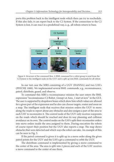
Figure 4. Structure of the comm<strong>and</strong> flow. A BML comm<strong>and</strong> for a robot group is send from the<br />
C2 System to the intelligent node on the UGV <strong>and</strong> is split up into BML comm<strong>and</strong>s for all robots<br />
In our test case the MRS consisting of a UGV (HANNA) <strong>and</strong> two UAVs<br />
(PSYCHE 1000). We implemented several BML comm<strong>and</strong>s, e.g., reconnaissance,<br />
patrol, distribute, guard, <strong>and</strong> observe.<br />
To comm<strong>and</strong> this MRS a reconnaissance mission the user enters the BML<br />
expression “reconnaissance C2 Robot_Group1 at Area_1 start at now” in the GUI.<br />
The user is supported by dropdown boxes which show him which values are allowed<br />
for a given part of the expression <strong>and</strong> he also can choose targets, routes <strong>and</strong> areas on<br />
a map. The intelligent node that receives that mission orders the UGV to move<br />
along the roads to report about any obstacles <strong>and</strong> also assigns a part of the area to<br />
each UAV to reconnoitre it. The control node of the UGV only receives waypoints<br />
on the roads which should be reached <strong>and</strong> does its way planning <strong>and</strong> collision<br />
avoidance on its own. The control nodes on the UAVs split their reconnoitre orders<br />
into move orders inside the area assigned to them. During execution the robots<br />
of course report their position but the UGV also reports a map. The map shows<br />
obstacles that were detected <strong>and</strong> which ways the robot can take. An example of this<br />
can be seen in Fig. 5.<br />
If the patrol comm<strong>and</strong> is given it is split up in a move order along the given<br />
patrol points for the UGV <strong>and</strong> the UAVs get a comm<strong>and</strong> to orbit the UGV.<br />
The distribute comm<strong>and</strong> is implemented by giving a move comm<strong>and</strong> to<br />
the center of the area. The area is split into 2 pieces <strong>and</strong> each of the UAV receives<br />
a move comm<strong>and</strong> to the center of one them.


