SILICON DESIGNS, INC - Instrumentation Devices
SILICON DESIGNS, INC - Instrumentation Devices
SILICON DESIGNS, INC - Instrumentation Devices

You also want an ePaper? Increase the reach of your titles
YUMPU automatically turns print PDFs into web optimized ePapers that Google loves.
<strong>SILICON</strong> <strong>DESIGNS</strong>, <strong>INC</strong> Model 2420<br />
TRIAXIAL DIGITAL ACCELEROMETER MODULE<br />
! 3 Axis Acceleration Sensing<br />
! Capacitive Micromachined<br />
! Nitrogen Damped<br />
! Use with model 3320 G-LOGGERTM or<br />
Interface to your Microprocessor<br />
! Digital Pulse Density Outputs<br />
! Fully Calibrated<br />
! Low Power Consumption<br />
! -55 to +125EC Operation<br />
! +5 V DC Power<br />
! Serialized for Traceability<br />
! Good EMI Resistance<br />
! Responds to DC & AC Acceleration<br />
! TTL / CMOS Compatible<br />
! Non Standard Ranges Available<br />
! Rugged Anodized Aluminum Module<br />
! D-Sub, 9-Pin (4 signal+2 Power) Connection<br />
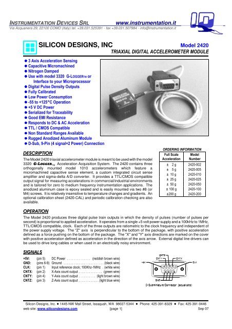
DESCRIPTION<br />
The Model 2420 triaxial accelerometer module is meant to be used with the model<br />
3320 G-LOGGER TM Acceleration Acquisition System. The 2420 contains three<br />
orthogonally mounted model 1010 accelerometers which feature a<br />
micromachined capacitive sense element, a custom integrated circuit sense<br />
amplifier and sigma-delta A/D converter. It provides a TTL/CMOS compatible<br />
output signal for measuring accelerations in commercial/industrial environments<br />
and is tailored for zero to medium frequency instrumentation applications. The<br />
anodized aluminum case is epoxy sealed and is easily mounted via two #8 (or<br />
M4) screws. It is relatively insensitive to temperature changes and gradients. An<br />
optional calibration sheet (2420-CAL) and periodic calibration checking are also<br />
available.<br />
ORDERING INFORMATION<br />
Full Scale Model<br />
Acceleration Number<br />
± 2 g 2420-002<br />
± 5 g 2420-005<br />
± 10 g 2420-010<br />
± 25 g 2420-025<br />
± 50 g 2420-050<br />
± 100 g 2420-100<br />
±200 g 2420-200<br />
OPERATION<br />
The Model 2420 produces three digital pulse train outputs in which the density of pulses (number of pulses per<br />
second) is proportional to applied acceleration. It operates from a single +5 volt power supply and a 100kHz to 1MHz,<br />
TTL/CMOS compatible, clock. Each of the three outputs are ratiometric to the clock frequency and independent of<br />
the power supply voltage. The "Z" axis is perpendicular to the bottom of the package, with positive acceleration<br />
defined as a force pushing on the bottom of the package. The "X" and "Y" axis directions are marked on the cover<br />
with positive acceleration defined as acceleration in the direction of the axis arrow. External digital line drivers can<br />
be used to drive long cables or when used in an electrically noisy environment.<br />
SIGNALS<br />
+5V: (pin 5) DC Power .............. (reddish brown wire)<br />
GND: (pins 6-9) Ground ........................(black wire)<br />
CLK: (pin 1) Input reference clock; 100Khz-1MHz . (white wire)<br />
CNTX: (pin 2) X-Axis count output .............. (green wire)<br />
CNTY: (pin 4) Y-Axis count output .......... (light brown wire)<br />
CNTZ: (pin 3) Z-Axis count output ............(light blue wire)<br />
Silicon Designs, Inc. ! 1445-NW Mall Street, Issaquah, WA 98027-5344 ! Phone: 425-391-8329 ! Fax: 425-391-0446<br />
web site: www.silicondesigns.com [page 1] Sep 07
ABSOLUTE MAXIMUM RATINGS *<br />
Operating Temperature (Case & Cable) . . . -55 to +125EC<br />
Operating Temperature (Connector) ..... -55 to +105EC<br />
Storage Temperature ................. -55 to +105EC<br />
Acceleration Over-range ............. 2000g for 0.1 ms<br />
Voltage on V DD to GND ................. -0.5V to 6.5V<br />
Voltage on Any Pin to GND 1 ........ -0.5V to V DD +0.5V<br />
Power Dissipation .........................100 mW<br />
* NOTICE: Stresses above those listed under "Absolute<br />
Maximum Ratings" may cause permanent damage to the<br />
device. These are stress ratings only. Functional operation<br />
of the device at or above these conditions is not implied.<br />
Exposure to absolute maximum rating conditions for<br />
extended periods may affect device reliability.<br />
ESD CONSIDERATIONS: The model 2420 triaxial<br />
accelerometer is a CMOS device subject to damage by<br />
large electrostatic discharges. Diode protection is<br />
provided on the inputs and outputs but care should be<br />
exercised during handling of the connector or cable wire<br />
ends (without connector). Individuals and tools should be<br />
grounded before coming in contact with the connector<br />
pins or cable wire ends (without connector).<br />
Model 2420 Triaxial Digital Accelerometer Module<br />
PERFORMANCE - By Model: V DD =5.0VDC, T C =25EC.<br />
MODEL NUMBER 2420-002 2420-005 2420-010 2420-025 2420-050 2420-100 2420-200 Units<br />
Input Range ±2 ±5 ±10 ±25 ±50 ±100 ±200 g<br />
Frequency Response (Nominal, 3 dB) 0 - 400 0 - 600 0 - 1000 0 - 1400 0 - 1600 0 - 1800 0 - 2000 Hz<br />
Sensitivity (F CLK =250kHz) 62.5 25.0 12.5 5.00 2.50 1.25 0.625 kHz/g<br />
Maximum Mechanical Shock (0.1 ms) 2000 g<br />
PERFORMANCE - All Models: Unless otherwise specified, V DD =5.0VDC, F CLK =250kHz, T C =25EC.<br />
PARAMETER Min Typ Max Units<br />
Cross Axis Sensitivity 2 3 %<br />
Bias Calibration Error 2 -002 2 4<br />
-005 thru -200 1 2<br />
% of F CLK (span)<br />
Bias Temperature Shift<br />
-002 150 400 (ppm of<br />
(T C =-55 to +125EC) 2 -005 thru -200 100 300 F CLK )/EC<br />
Scale Factor Calibration Error 2, 3 1 2 %<br />
Scale Factor Temperature Shift (T C =-55 to +125EC) 2 +300 ppm/EC<br />
Non-Linearity<br />
-002 thru -100 0.5 1.0<br />
(-90% to +90% of Full Scale) 3 -200 0.7 1.5<br />
% of span<br />
Power Supply Rejection Ratio 40 dB<br />
Operating Voltage 4.5 5.0 5.5 V<br />
Operating Current 2 6.0 9.0 mA<br />
Clock Input Voltage Range (with respect to GND) -0.5 V DD +0.5 V<br />
Mass (not including cable) 21 grams<br />
Cable Mass 15 grams/meter<br />
Note 1: Voltages on the CLK & CNT signal wires may exceed 0.5 volt above or below the supply voltage provided the current is limited to 1 mA.<br />
Note 2: Tighter tolerances available on special order.<br />
Note 3: 100g and greater versions are tested from -65g to +65g.<br />
ALTERNATE OUTPUT VERSION AVAILABLE: A custom version may be ordered which provides the DIR (direction) output<br />
instead of the CNT (count) output. For a description of the DIR signal, see the model 1010 data sheet.<br />
SPECIFICATIONS SUBJECT TO CHANGE WITHOUT NOTICE<br />
Silicon Designs, Inc. ! 1445 NW Mall Street, Issaquah, WA 98027-5344 ! Phone: 425-391-8329 ! Fax: 425-391-0446<br />
web site: www.silicondesigns.com [page 2] Sep 07
SIGNAL DESCRIPTIONS<br />
Model 2420 Triaxial Digital Accelerometer Module<br />
CLK (input): Reference clock input. This hysteresis threshold input must be driven by a 50% duty cycle square wave signal.<br />
Factory Calibration is performed at 250 kHz but the 2420 will operate at frequencies as low as 100 kHz or as high as 1 MHz.<br />
CNT (output): Pin 10. Count output. A return-to-zero type digital pulse stream whose pulse width is equal to the input CLK logic<br />
high time. The CNT pulse rate increases with positive acceleration. The device experiences positive (+1g) acceleration with<br />
its lid facing up in the earth’s gravitational field. This signal is meant to drive an up-counter directly.<br />
Pulses from the CNT output are meant to be accumulated in a hardware counter. Each pulse accumulation or sample, reflects<br />
the average acceleration (change in velocity) over that interval. The sample period or “gate time” over which these pulses are<br />
accumulated determines both the bandwidth and quantization of the measurement.<br />
Quantization (g' s) =<br />
g<br />
f<br />
CNT<br />
FORCE<br />
g<br />
SPAN<br />
• fSR<br />
⎛ 1 g<br />
= fCLK<br />
⎜ +<br />
⎝ 2 g<br />
⎛ f<br />
CNT<br />
= gSPAN<br />
⎜ −<br />
⎝ f<br />
f<br />
CLK<br />
CLK<br />
FORCE<br />
SPAN<br />
1⎞<br />
⎟<br />
2⎠<br />
⎞<br />
⎟<br />
⎠<br />
Where:<br />
g<br />
g<br />
SPAN<br />
f<br />
f<br />
f<br />
SR<br />
CLK<br />
CNT<br />
FORCE<br />
= 2*( full scale acceleration in g' s)<br />
= CNT sample rate in Hertz<br />
= accelerometer clock rate in Hertz<br />
= CNT pulse rate in pulses / sec<br />
= acceleration in gravity units<br />
1 g = 9.807 m / s 2 or 32.175ft / s 2<br />
The first equation above shows that as the sample rate is reduced (i.e. a longer sample period), the quantization becomes finer<br />
but bandwidth is reduced. Conversely, as the sample rate is increased, quantization becomes coarser but the bandwidth of the<br />
measurement is increased. The second and third equations show how the CNT pulse frequency equates to the applied g-force.<br />
When using a frequency counter to monitor the CNT output pulse rate, a counter with a DC coupled input must be used. The<br />
CNT output is a return-to-zero signal whose duty cycle varies from zero to fifty percent, from minus full scale to positive full scale<br />
acceleration. A frequency counter with an AC coupled input will provide an erroneous reading as the duty cycle varies<br />
appreciably from fifty percent.<br />
CABLE LENGTH CONSIDERATIONS<br />
Cable lengths of up to 45 meters (150 feet) can be added to the model 2420's standard 1 meter cable when it is being used with<br />
a Model 3320 G-L<br />
-LOGGER TM . The extension cable must however, be a longer version of the G-L<br />
-LOGGER TM 9 conductor flat cable<br />
instead of the 2420's round cable to reduce crosstalk between the CNT and CLK signals. 15 meter (50 foot) cable lengths of<br />
DB9 male to DB9 female flat extension cable are available on special order.<br />
SPECIFICATIONS SUBJECT TO CHANGE WITHOUT NOTICE<br />
Silicon Designs, Inc. ! 1445 NW Mall Street, Issaquah, WA 98027-5344 ! Phone: 425-391-8329 ! Fax: 425-391-0446<br />
web site: www.silicondesigns.com [page 3] Sep 07
Model 2420 Triaxial Digital Accelerometer Module<br />
SENSOR LOCATIONS<br />
SPECIFICATIONS SUBJECT TO CHANGE WITHOUT NOTICE<br />
Silicon Designs, Inc. ! 1445 NW Mall Street, Issaquah, WA 98027-5344 ! Phone: 425-391-8329 ! Fax: 425-391-0446<br />
web site: www.silicondesigns.com [page 4] Sep 07
![98L!%$5 gYf]Yg - INSTRUMENTATION DEVICES](https://img.yumpu.com/50611686/1/184x260/98l5-gyfyg-instrumentation-devices.jpg?quality=85)