SPIM S20: A MIPS R2000 Simulator
SPIM S20: A MIPS R2000 Simulator
SPIM S20: A MIPS R2000 Simulator

You also want an ePaper? Increase the reach of your titles
YUMPU automatically turns print PDFs into web optimized ePapers that Google loves.
<strong>SPIM</strong> <strong>S20</strong>: A <strong>MIPS</strong> <strong>R2000</strong> <strong>Simulator</strong> ∗<br />
“ 1 th the performance at none of the cost”<br />
25<br />
James R. Larus<br />
larus@cs.wisc.edu<br />
Computer Sciences Department<br />
University of Wisconsin–Madison<br />
1210 West Dayton Street<br />
Madison, WI 53706, USA<br />
608-262-9519<br />
Copyright c○1990–1997 by James R. Larus<br />
(This document may be copied without royalties,<br />
so long as this copyright notice remains on it.)<br />
1 <strong>SPIM</strong><br />
<strong>SPIM</strong> <strong>S20</strong> is a simulator that runs programs for the <strong>MIPS</strong> <strong>R2000</strong>/R3000 RISC computers. 1 <strong>SPIM</strong><br />
can read and immediately execute files containing assembly language. <strong>SPIM</strong> is a self-contained<br />
system for running these programs and contains a debugger and interface to a few operating system<br />
services.<br />
The architecture of the <strong>MIPS</strong> computers is simple and regular, which makes it easy to learn and<br />
understand. The processor contains 32 general-purpose 32-bit registers and a well-designed instruction<br />
set that make it a propitious target for generating code in a compiler.<br />
However, the obvious question is: why use a simulator when many people have workstations<br />
that contain a hardware, and hence significantly faster, implementation of this computer One reason<br />
is that these workstations are not generally available. Another reason is that these machine<br />
will not persist for many years because of the rapid progress leading to new and faster computers.<br />
Unfortunately, the trend is to make computers faster by executing several instructions concurrently,<br />
which makes their architecture more difficult to understand and program. The <strong>MIPS</strong> architecture<br />
may be the epitome of a simple, clean RISC machine.<br />
In addition, simulators can provide a better environment for low-level programming than an<br />
actual machine because they can detect more errors and provide more features than an actual computer.<br />
For example, <strong>SPIM</strong> has a X-window interface that is better than most debuggers for the actual<br />
machines.<br />
Finally, simulators are an useful tool for studying computers and the programs that run on them.<br />
Because they are implemented in software, not silicon, they can be easily modified to add new instructions,<br />
build new systems such as multiprocessors, or simply to collect data.<br />
∗ I grateful to the many students at UW who used <strong>SPIM</strong> in their courses and happily found bugs in a professor’s code. In<br />
particular, the students in CS536, Spring 1990, painfully found the last few bugs in an “already-debugged” simulator. I am<br />
grateful for their patience and persistence. Alan Yuen-wui Siow wrote the X-window interface.<br />
1 For a description of the real machines, see Gerry Kane and Joe Heinrich, <strong>MIPS</strong> RISC Architecture, Prentice Hall, 1992.<br />
1
1.1 Simulation of a Virtual Machine<br />
The <strong>MIPS</strong> architecture, like that of most RISC computers, is difficult to program directly because<br />
of its delayed branches, delayed loads, and restricted address modes. This difficulty is tolerable<br />
since these computers were designed to be programmed in high-level languages and so present<br />
an interface designed for compilers, not programmers. A good part of the complexity results from<br />
delayed instructions. A delayed branch takes two cycles to execute. In the second cycle, the instruction<br />
immediately following the branch executes. This instruction can perform useful work that normally<br />
would have been done before the branch or it can be a nop (no operation). Similarly, delayed loads<br />
take two cycles so the instruction immediately following a load cannot use the value loaded from<br />
memory.<br />
<strong>MIPS</strong> wisely choose to hide this complexity by implementing a virtual machine with their assembler.<br />
This virtual computer appears to have non-delayed branches and loads and a richer instruction<br />
set than the actual hardware. The assembler reorganizes (rearranges) instructions to fill the delay<br />
slots. It also simulates the additional, pseudoinstructions by generating short sequences of actual<br />
instructions.<br />
By default, <strong>SPIM</strong> simulates the richer, virtual machine. It can also simulate the actual hardware.<br />
We will describe the virtual machine and only mention in passing features that do not belong to<br />
the actual hardware. In doing so, we are following the convention of <strong>MIPS</strong> assembly language<br />
programmers (and compilers), who routinely take advantage of the extended machine. Instructions<br />
marked with a dagger (†) are pseudoinstructions.<br />
1.2 <strong>SPIM</strong> Interface<br />
<strong>SPIM</strong> provides a simple terminal and a X-window interface. Both provide equivalent functionality,<br />
but the X interface is generally easier to use and more informative.<br />
spim, the terminal version, and xspim, the X version, have the following command-line options:<br />
-bare<br />
Simulate a bare <strong>MIPS</strong> machine without pseudoinstructions or the additional addressing modes<br />
provided by the assembler. Implies -quiet.<br />
-asm<br />
Simulate the virtual <strong>MIPS</strong> machine provided by the assembler. This is the default.<br />
-pseudo<br />
Accept pseudoinstructions in assembly code.<br />
-nopseudo<br />
Do not accept pseudoinstructions in assembly code.<br />
-notrap<br />
Do not load the standard trap handler. This trap handler has two functions that must be assumed<br />
by the user’s program. First, it handles traps. When a trap occurs, <strong>SPIM</strong> jumps to<br />
location 0x80000080, which should contain code to service the exception. Second, this file contains<br />
startup code that invokes the routine main. Without the trap handler, execution begins<br />
at the instruction labeled start.<br />
-trap<br />
Load the standard trap handler. This is the default.<br />
-trap file<br />
Load the trap handler in the file.<br />
-noquiet<br />
Print a message when an exception occurs. This is the default.<br />
2
-quiet<br />
Do not print a message at an exception.<br />
-nomapped io<br />
Disable the memory-mapped IO facility (see Section 5).<br />
-mapped io<br />
Enable the memory-mapped IO facility (see Section 5). Programs that use <strong>SPIM</strong> syscalls (see<br />
Section 1.5) to read from the terminal should not also use memory-mapped IO.<br />
-file<br />
Load and execute the assembly code in the file.<br />
-s seg size Sets the initial size of memory segment seg to be size bytes. The memory segments<br />
are named: text, data, stack, ktext, and kdata. For example, the pair of arguments<br />
-sdata 2000000 starts the user data segment at 2,000,000 bytes.<br />
-lseg size Sets the limit on how large memory segment seg can grow to be size bytes. The<br />
memory segments that can grow are: data, stack, and kdata.<br />
1.2.1 Terminal Interface<br />
The terminal interface (spim) provides the following commands:<br />
exit<br />
Exit the simulator.<br />
read "file"<br />
Read file of assembly language commands into <strong>SPIM</strong>’s memory. If the file has already been<br />
read into <strong>SPIM</strong>, the system should be cleared (see reinitialize, below) or global symbols<br />
will be multiply defined.<br />
load "file"<br />
Synonym for read.<br />
run <br />
Start running a program. If the optional address addr is provided, the program starts at that<br />
address. Otherwise, the program starts at the global symbol start, which is defined by the<br />
default trap handler to call the routine at the global symbol main with the usual <strong>MIPS</strong> calling<br />
convention.<br />
step <br />
Step the program for N (default: 1) instructions. Print instructions as they execute.<br />
continue<br />
Continue program execution without stepping.<br />
print $N<br />
Print register N.<br />
print $fN<br />
Print floating point register N.<br />
print addr<br />
Print the contents of memory at address addr.<br />
print sym<br />
Print the contents of the symbol table, i.e., the addresses of the global (but not local) symbols.<br />
3
einitialize<br />
Clear the memory and registers.<br />
breakpoint addr<br />
Set a breakpoint at address addr. addr can be either a memory address or symbolic label.<br />
delete addr<br />
Delete all breakpoints at address addr.<br />
list<br />
List all breakpoints.<br />
.<br />
Rest of line is an assembly instruction that is stored in memory.<br />
<br />
A newline reexecutes previous command.<br />
<br />
Print a help message.<br />
Most commands can be abbreviated to their unique prefix e.g., ex, re, l, ru, s, p. More dangerous<br />
commands, such as reinitialize, require a longer prefix.<br />
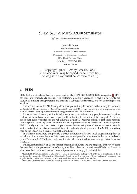
1.2.2 X-Window Interface<br />
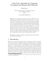
The X version of <strong>SPIM</strong>, xspim, looks different, but should operate in the same manner as spim. The<br />
X window has five panes (see Figure 1). The top pane displays the contents of the registers. It is<br />
continually updated, except while a program is running.<br />
The next pane contains the buttons that control the simulator:<br />
quit<br />
Exit from the simulator.<br />
load<br />
Read a source file into memory.<br />
run<br />
Start the program running.<br />
step<br />
Single-step through a program.<br />
clear<br />
Reinitialize registers or memory.<br />
set value<br />
Set the value in a register or memory location.<br />
print<br />
Print the value in a register or memory location.<br />
breakpoint<br />
Set or delete a breakpoint or list all breakpoints.<br />
help<br />
Print a help message.<br />
terminal<br />
Raise or hide the console window.<br />
4
xspim<br />
Register<br />
Display<br />
Control<br />
Buttons<br />
User and<br />
Kernel<br />
Text<br />
Segments<br />
PC = 00000000 EPC = 00000000 Cause = 0000000 BadVaddr = 00000000<br />
Status= 00000000 HI = 00000000 LO = 0000000<br />
General Registers<br />
R0 (r0) = 00000000 R8 (t0) = 00000000 R16 (s0) = 0000000 R24 (t8) = 00000000<br />
R1 (at) = 00000000 R9 (t1) = 00000000 R17 (s1) = 0000000 R25 (s9) = 00000000<br />
R2 (v0) = 00000000 R10 (t2) = 00000000 R18 (s2) = 0000000 R26 (k0) = 00000000<br />
R3 (v1) 00000000 R11 (t3) 00000000 R19 (s3) 0000000 R27 (k1) 00000000<br />
R4 (a0) = 00000000 R12 (t4) = 00000000 R20 (s4) = 0000000 R28 (gp) = 00000000<br />
R5 (a1) = 00000000 R13 (t5) = 00000000 R21 (s5) = 0000000 R29 (gp) = 00000000<br />
R6 (a2) = 00000000 R14 (t6) = 00000000 R22 (s6) = 0000000 R30 (s8) = 00000000<br />
R7 (a3) = 00000000 R15 (t7) = 00000000 R23 (s7) = 0000000 R31 (ra) = 00000000<br />
Double Floating Point Registers<br />
FP0 = 0.000000 FP8 = 0.000000 FP16 = 0.00000 FP24 = 0.000000<br />
FP2 = 0.000000 FP10 = 0.000000 FP18 = 0.00000 FP26 = 0.000000<br />
FP4 = 0.000000 FP12 = 0.000000 FP20 = 0.00000 FP28 = 0.000000<br />
FP6 = 0.000000 FP14 = 0.000000 FP22 = 0.00000 FP30 = 0.000000<br />
Single Floating Point Registers<br />
quit load run step clear set value<br />
print breakpt help terminal mode<br />
Text Segments<br />
[0x00400000] 0x8fa40000 lw R4, 0(R29) []<br />
[0x00400004] 0x27a50004 addiu R5, R29, 4 []<br />
[0x00400008] 0x24a60004 addiu R6, R5, 4 []<br />
[0x0040000c] 0x00041090 sll R2, R4, 2<br />
[0x00400010] 0x00c23021 addu R6, R6, R2<br />
[0x00400014] 0x0c000000 jal 0x00000000 []<br />
[0x00400018] 0x3402000a ori R0, R0, 10 []<br />
[0x0040001c] 0x0000000c syscall<br />
Data Segments<br />
Data and<br />
Stack<br />
Segments<br />
[0x10000000]...[0x10010000] 0x00000000<br />
[0x10010004] 0x74706563 0x206e6f69 0x636f2000<br />
[0x10010010] 0x72727563 0x61206465 0x6920646e 0x726f6e67<br />
[0x10010020] 0x000a6465 0x495b2020 0x7265746e 0x74707572<br />
[0x10010030] 0x0000205d 0x20200000 0x616e555b 0x6e67696c<br />
[0x10010040] 0x61206465 0x65726464 0x69207373 0x6e69206e<br />
[0x10010050] 0x642f7473 0x20617461 0x63746566 0x00205d68<br />
[0x10010060] 0x555b2020 0x696c616e 0x64656e67 0x64646120<br />
[0x10010070] 0x73736572 0x206e6920 0x726f7473 0x00205d65<br />
<strong>SPIM</strong> Version 3.2 of January 14, 1990<br />
<strong>SPIM</strong><br />
Messages<br />
Figure 1: X-window interface to <strong>SPIM</strong>.<br />
5
mode<br />
Set <strong>SPIM</strong> operating modes.<br />
The next two panes display the memory contents. The top one shows instructions from the user<br />
and kernel text segments. 2 The first few instructions in the text segment are startup code ( start)<br />
that loads argc and argv into registers and invokes the main routine.<br />
The lower of these two panes displays the data and stack segments. Both panes are updated as a<br />
program executes.<br />
The bottom pane is used to display messages from the simulator. It does not display output from<br />
an executing program. When a program reads or writes, its IO appears in a separate window, called<br />
the Console, which pops up when needed.<br />
1.3 Surprising Features<br />
Although <strong>SPIM</strong> faithfully simulates the <strong>MIPS</strong> computer, it is a simulator and certain things are not<br />
identical to the actual computer. The most obvious differences are that instruction timing and the<br />
memory systems are not identical. <strong>SPIM</strong> does not simulate caches or memory latency, nor does it<br />
accurate reflect the delays for floating point operations or multiplies and divides.<br />
Another surprise (which occurs on the real machine as well) is that a pseudoinstruction expands<br />
into several machine instructions. When single-stepping or examining memory, the instructions that<br />
you see are slightly different from the source program. The correspondence between the two sets of<br />
instructions is fairly simple since <strong>SPIM</strong> does not reorganize the instructions to fill delay slots.<br />
1.4 Assembler Syntax<br />
Comments in assembler files begin with a sharp-sign (#). Everything from the sharp-sign to the end<br />
of the line is ignored.<br />
Identifiers are a sequence of alphanumeric characters, underbars ( ), and dots (.) that do not<br />
begin with a number. Opcodes for instructions are reserved words that are not valid identifiers.<br />
Labels are declared by putting them at the beginning of a line followed by a colon, for example:<br />
.data<br />
item: .word 1<br />
.text<br />
.globl main<br />
main: lw $t0, item<br />
# Must be global<br />
Strings are enclosed in double-quotes ("). Special characters in strings follow the C convention:<br />
newline \n<br />
tab \t<br />
quote \"<br />
<strong>SPIM</strong> supports a subset of the assembler directives provided by the <strong>MIPS</strong> assembler:<br />
.align n<br />
Align the next datum on a 2 n byte boundary. For example, .align 2 aligns the next value on<br />
a word boundary. .align 0 turns off automatic alignment of .half, .word, .float, and<br />
.double directives until the next .data or .kdata directive.<br />
.ascii str<br />
Store the string in memory, but do not null-terminate it.<br />
2 These instructions are real—not pseudo—<strong>MIPS</strong> instructions. <strong>SPIM</strong> translates assembler pseudoinstructions to 1–3 <strong>MIPS</strong><br />
instructions before storing the program in memory. Each source instruction appears as a comment on the first instruction to<br />
which it is translated.<br />
6
.asciiz str<br />
Store the string in memory and null-terminate it.<br />
.byte b1, ..., bn<br />
Store the n values in successive bytes of memory.<br />
.data <br />
The following data items should be stored in the data segment. If the optional argument addr<br />
is present, the items are stored beginning at address addr.<br />
.double d1, ..., dn<br />
Store the n floating point double precision numbers in successive memory locations.<br />
.extern sym size<br />
Declare that the datum stored at sym is size bytes large and is a global symbol. This directive<br />
enables the assembler to store the datum in a portion of the data segment that is efficiently<br />
accessed via register $gp.<br />
.float f1, ..., fn<br />
Store the n floating point single precision numbers in successive memory locations.<br />
.globl sym<br />
Declare that symbol sym is global and can be referenced from other files.<br />
.half h1, ..., hn<br />
Store the n 16-bit quantities in successive memory halfwords.<br />
.kdata <br />
The following data items should be stored in the kernel data segment. If the optional argument<br />
addr is present, the items are stored beginning at address addr.<br />
.ktext <br />
The next items are put in the kernel text segment. In <strong>SPIM</strong>, these items may only be instructions<br />
or words (see the .word directive below). If the optional argument addr is present, the items<br />
are stored beginning at address addr.<br />
.space n<br />
Allocate n bytes of space in the current segment (which must be the data segment in <strong>SPIM</strong>).<br />
.text <br />
The next items are put in the user text segment. In <strong>SPIM</strong>, these items may only be instructions<br />
or words (see the .word directive below). If the optional argument addr is present, the items<br />
are stored beginning at address addr.<br />
.word w1, ..., wn<br />
Store the n 32-bit quantities in successive memory words.<br />
<strong>SPIM</strong> does not distinguish various parts of the data segment (.data, .rdata, and .sdata).<br />
1.5 System Calls<br />
<strong>SPIM</strong> provides a small set of operating-system-like services through the system call (syscall) instruction.<br />
To request a service, a program loads the system call code (see Table 1) into register $v0<br />
and the arguments into registers $a0. . .$a3 (or $f12 for floating point values). System calls that<br />
return values put their result in register $v0 (or $f0 for floating point results). For example, to print<br />
“the answer = 5”, use the commands:<br />
7
Service System Call Code Arguments Result<br />
print int 1 $a0 = integer<br />
print float 2 $f12 = float<br />
print double 3 $f12 = double<br />
print string 4 $a0 = string<br />
read int 5 integer (in $v0)<br />
read float 6 float (in $f0)<br />
read double 7 double (in $f0)<br />
read string 8 $a0 = buffer, $a1 = length<br />
sbrk 9 $a0 = amount address (in $v0)<br />
exit 10<br />
Table 1: System services.<br />
.data<br />
str: .asciiz "the answer = "<br />
.text<br />
li $v0, 4 # system call code for print_str<br />
la $a0, str # address of string to print<br />
syscall<br />
# print the string<br />
li $v0, 1<br />
li $a0, 5<br />
syscall<br />
# system call code for print_int<br />
# integer to print<br />
# print it<br />
print int is passed an integer and prints it on the console. print float prints a single floating<br />
point number. print double prints a double precision number. print string is passed a<br />
pointer to a null-terminated string, which it writes to the console.<br />
read int, read float, and read double read an entire line of input up to and including the<br />
newline. Characters following the number are ignored. read string has the same semantics as<br />
the Unix library routine fgets. It reads up to n − 1 characters into a buffer and terminates the string<br />
with a null byte. If there are fewer characters on the current line, it reads through the newline and<br />
again null-terminates the string. Warning: programs that use these syscalls to read from the terminal<br />
should not use memory-mapped IO (see Section 5).<br />
sbrk returns a pointer to a block of memory containing n additional bytes. exit stops a program<br />
from running.<br />
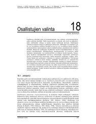
2 Description of the <strong>MIPS</strong> <strong>R2000</strong><br />
A <strong>MIPS</strong> processor consists of an integer processing unit (the CPU) and a collection of coprocessors<br />
that perform ancillary tasks or operate on other types of data such as floating point numbers (see<br />
Figure 2). <strong>SPIM</strong> simulates two coprocessors. Coprocessor 0 handles traps, exceptions, and the virtual<br />
memory system. <strong>SPIM</strong> simulates most of the first two and entirely omits details of the memory<br />
system. Coprocessor 1 is the floating point unit. <strong>SPIM</strong> simulates most aspects of this unit.<br />
2.1 CPU Registers<br />
The <strong>MIPS</strong> (and <strong>SPIM</strong>) central processing unit contains 32 general purpose 32-bit registers that are<br />
numbered 0–31. Register n is designated by $n. Register $0 always contains the hardwired value 0.<br />
<strong>MIPS</strong> has established a set of conventions as to how registers should be used. These suggestions are<br />
guidelines, which are not enforced by the hardware. However a program that violates them will not<br />
work properly with other software. Table 2 lists the registers and describes their intended use.<br />
8
Register Name Number Usage<br />
zero 0 Constant 0<br />
at 1 Reserved for assembler<br />
v0 2 Expression evaluation and<br />
v1 3 results of a function<br />
a0 4 Argument 1<br />
a1 5 Argument 2<br />
a2 6 Argument 3<br />
a3 7 Argument 4<br />
t0 8 Temporary (not preserved across call)<br />
t1 9 Temporary (not preserved across call)<br />
t2 10 Temporary (not preserved across call)<br />
t3 11 Temporary (not preserved across call)<br />
t4 12 Temporary (not preserved across call)<br />
t5 13 Temporary (not preserved across call)<br />
t6 14 Temporary (not preserved across call)<br />
t7 15 Temporary (not preserved across call)<br />
s0 16 Saved temporary (preserved across call)<br />
s1 17 Saved temporary (preserved across call)<br />
s2 18 Saved temporary (preserved across call)<br />
s3 19 Saved temporary (preserved across call)<br />
s4 20 Saved temporary (preserved across call)<br />
s5 21 Saved temporary (preserved across call)<br />
s6 22 Saved temporary (preserved across call)<br />
s7 23 Saved temporary (preserved across call)<br />
t8 24 Temporary (not preserved across call)<br />
t9 25 Temporary (not preserved across call)<br />
k0 26 Reserved for OS kernel<br />
k1 27 Reserved for OS kernel<br />
gp 28 Pointer to global area<br />
sp 29 Stack pointer<br />
fp 30 Frame pointer<br />
ra 31 Return address (used by function call)<br />
Table 2: <strong>MIPS</strong> registers and the convention governing their use.<br />
9
Memory<br />
CPU<br />
Arithmetic<br />
Unit<br />
Registers<br />
$0<br />
.<br />
.<br />
.<br />
$31<br />
Multiply<br />
Divide<br />
Lo<br />
Hi<br />
FPU (Coprocessor 1)<br />
Registers<br />
$0<br />
.<br />
.<br />
.<br />
$31<br />
Arithmetic<br />
Unit<br />
Coprocessor 0 (Traps and Memory)<br />
BadVAddr<br />
Status<br />
Cause<br />
EPC<br />
Figure 2: <strong>MIPS</strong> <strong>R2000</strong> CPU and FPU<br />
Registers $at (1), $k0 (26), and $k1 (27) are reserved for use by the assembler and operating<br />
system.<br />
Registers $a0–$a3 (4–7) are used to pass the first four arguments to routines (remaining arguments<br />
are passed on the stack). Registers $v0 and $v1 (2, 3) are used to return values from functions.<br />
Registers $t0–$t9 (8–15, 24, 25) are caller-saved registers used for temporary quantities that do not<br />
need to be preserved across calls. Registers $s0–$s7 (16–23) are callee-saved registers that hold<br />
long-lived values that should be preserved across calls.<br />
Register $sp (29) is the stack pointer, which points to the last location in use on the stack. 3 Register<br />
$fp (30) is the frame pointer. 4 Register $ra (31) is written with the return address for a call by<br />
the jal instruction.<br />
Register $gp (28) is a global pointer that points into the middle of a 64K block of memory in the<br />
heap that holds constants and global variables. The objects in this heap can be quickly accessed with<br />
a single load or store instruction.<br />
In addition, coprocessor 0 contains registers that are useful to handle exceptions. <strong>SPIM</strong> does not<br />
implement all of these registers, since they are not of much use in a simulator or are part of the<br />
memory system, which is not implemented. However, it does provide the following:<br />
Register Name Number Usage<br />
BadVAddr 8 Memory address at which address exception occurred<br />
Status 12 Interrupt mask and enable bits<br />
Cause 13 Exception type and pending interrupt bits<br />
EPC 14 Address of instruction that caused exception<br />
3 In earlier version of <strong>SPIM</strong>, $sp was documented as pointing at the first free word on the stack (not the last word of the<br />
stack frame). Recent <strong>MIPS</strong> documents have made it clear that this was an error. Both conventions work equally well, but we<br />
choose to follow the real system.<br />
4 The <strong>MIPS</strong> compiler does not use a frame pointer, so this register is used as callee-saved register $s8.<br />
10
15 10 5 4 3 2 1 0<br />
Interrupt<br />
Mask<br />
Kernel/<br />
User<br />
Old Previous Current<br />
Interrupt<br />
Enable<br />
Kernel/<br />
User<br />
Interrupt<br />
Enable<br />
Kernel/<br />
User<br />
Interrupt<br />
Enable<br />
Figure 3: The Status register.<br />
15<br />
10<br />
5<br />
2<br />
Pending<br />
Interrupts<br />
Exception<br />
Code<br />
Figure 4: The Cause register.<br />
These registers are part of coprocessor 0’s register set and are accessed by the lwc0, mfc0, mtc0,<br />
and swc0 instructions.<br />
Figure 3 describes the bits in the Status register that are implemented by <strong>SPIM</strong>. The interrupt<br />
mask contains a bit for each of the five interrupt levels. If a bit is one, interrupts at that level are<br />
allowed. If the bit is zero, interrupts at that level are disabled. The low six bits of the Status<br />
register implement a three-level stack for the kernel/user and interrupt enable bits. The<br />
kernel/user bit is 0 if the program was running in the kernel when the interrupt occurred and 1<br />
if it was in user mode. If the interrupt enable bit is 1, interrupts are allowed. If it is 0, they are<br />
disabled. At an interrupt, these six bits are shifted left by two bits, so the current bits become the<br />
previous bits and the previous bits become the old bits. The current bits are both set to 0 (i.e., kernel<br />
mode with interrupts disabled).<br />
Figure 4 describes the bits in the Cause registers. The five pending interrupt bits correspond<br />
to the five interrupt levels. A bit becomes 1 when an interrupt at its level has occurred but has not<br />
been serviced. The exception code register contains a code from the following table describing<br />
the cause of an exception.<br />
Number Name Description<br />
0 INT External interrupt<br />
4 ADDRL Address error exception (load or instruction fetch)<br />
5 ADDRS Address error exception (store)<br />
6 IBUS Bus error on instruction fetch<br />
7 DBUS Bus error on data load or store<br />
8 SYSCALL Syscall exception<br />
9 BKPT Breakpoint exception<br />
10 RI Reserved instruction exception<br />
12 OVF Arithmetic overflow exception<br />
2.2 Byte Order<br />
Processors can number the bytes within a word to make the byte with the lowest number either the<br />
leftmost or rightmost one. The convention used by a machine is its byte order. <strong>MIPS</strong> processors can<br />
11
operate with either big-endian byte order:<br />
Byte #<br />
0 1 2 3<br />
or little-endian byte order:<br />
Byte #<br />
3 2 1 0<br />
<strong>SPIM</strong> operates with both byte orders. <strong>SPIM</strong>’s byte order is determined by the byte order of the<br />
underlying hardware running the simulator. On a DECstation 3100, <strong>SPIM</strong> is little-endian, while on<br />
a HP Bobcat, Sun 4 or PC/RT, <strong>SPIM</strong> is big-endian.<br />
2.3 Addressing Modes<br />
<strong>MIPS</strong> is a load/store architecture, which means that only load and store instructions access memory.<br />
Computation instructions operate only on values in registers. The bare machine provides only one<br />
memory addressing mode: c(rx), which uses the sum of the immediate (integer) c and the contents<br />
of register rx as the address. The virtual machine provides the following addressing modes for load<br />
and store instructions:<br />
Format<br />
(register)<br />
imm<br />
imm (register)<br />
symbol<br />
symbol ± imm<br />
symbol ± imm (register)<br />
Address Computation<br />
contents of register<br />
immediate<br />
immediate + contents of register<br />
address of symbol<br />
address of symbol + or − immediate<br />
address of symbol + or − (immediate + contents of register)<br />
Most load and store instructions operate only on aligned data. A quantity is aligned if its memory<br />
address is a multiple of its size in bytes. Therefore, a halfword object must be stored at even addresses<br />
and a full word object must be stored at addresses that are a multiple of 4. However, <strong>MIPS</strong><br />
provides some instructions for manipulating unaligned data.<br />
2.4 Arithmetic and Logical Instructions<br />
In all instructions below, Src2 can either be a register or an immediate value (a 16 bit integer). The<br />
immediate forms of the instructions are only included for reference. The assembler will translate the<br />
more general form of an instruction (e.g., add) into the immediate form (e.g., addi) if the second<br />
argument is constant.<br />
abs Rdest, Rsrc Absolute Value †<br />
Put the absolute value of the integer from register Rsrc in register Rdest.<br />
add Rdest, Rsrc1, Src2<br />
Addition (with overflow)<br />
addi Rdest, Rsrc1, Imm<br />
Addition Immediate (with overflow)<br />
addu Rdest, Rsrc1, Src2<br />
Addition (without overflow)<br />
addiu Rdest, Rsrc1, Imm<br />
Addition Immediate (without overflow)<br />
Put the sum of the integers from register Rsrc1 and Src2 (or Imm) into register Rdest.<br />
and Rdest, Rsrc1, Src2<br />
AND<br />
andi Rdest, Rsrc1, Imm<br />
AND Immediate<br />
Put the logical AND of the integers from register Rsrc1 and Src2 (or Imm) into register Rdest.<br />
div Rsrc1, Rsrc2<br />
divu Rsrc1, Rsrc2<br />
Divide (signed)<br />
Divide (unsigned)<br />
12
Divide the contents of the two registers. divu treats is operands as unsigned values. Leave the<br />
quotient in register lo and the remainder in register hi. Note that if an operand is negative, the<br />
remainder is unspecified by the <strong>MIPS</strong> architecture and depends on the conventions of the machine<br />
on which <strong>SPIM</strong> is run.<br />
div Rdest, Rsrc1, Src2 Divide (signed, with overflow) †<br />
divu Rdest, Rsrc1, Src2 Divide (unsigned, without overflow) †<br />
Put the quotient of the integers from register Rsrc1 and Src2 into register Rdest. divu treats is<br />
operands as unsigned values.<br />
mul Rdest, Rsrc1, Src2 Multiply (without overflow) †<br />
mulo Rdest, Rsrc1, Src2 Multiply (with overflow) †<br />
mulou Rdest, Rsrc1, Src2 Unsigned Multiply (with overflow) †<br />
Put the product of the integers from register Rsrc1 and Src2 into register Rdest.<br />
mult Rsrc1, Rsrc2<br />
Multiply<br />
multu Rsrc1, Rsrc2<br />
Unsigned Multiply<br />
Multiply the contents of the two registers. Leave the low-order word of the product in register lo<br />
and the high-word in register hi.<br />
neg Rdest, Rsrc Negate Value (with overflow) †<br />
negu Rdest, Rsrc Negate Value (without overflow) †<br />
Put the negative of the integer from register Rsrc into register Rdest.<br />
nor Rdest, Rsrc1, Src2<br />
Put the logical NOR of the integers from register Rsrc1 and Src2 into register Rdest.<br />
NOR<br />
not Rdest, Rsrc NOT †<br />
Put the bitwise logical negation of the integer from register Rsrc into register Rdest.<br />
or Rdest, Rsrc1, Src2<br />
OR<br />
ori Rdest, Rsrc1, Imm<br />
OR Immediate<br />
Put the logical OR of the integers from register Rsrc1 and Src2 (or Imm) into register Rdest.<br />
rem Rdest, Rsrc1, Src2 Remainder †<br />
remu Rdest, Rsrc1, Src2 Unsigned Remainder †<br />
Put the remainder from dividing the integer in register Rsrc1 by the integer in Src2 into register<br />
Rdest. Note that if an operand is negative, the remainder is unspecified by the <strong>MIPS</strong> architecture<br />
and depends on the conventions of the machine on which <strong>SPIM</strong> is run.<br />
rol Rdest, Rsrc1, Src2 Rotate Left †<br />
ror Rdest, Rsrc1, Src2 Rotate Right †<br />
Rotate the contents of register Rsrc1 left (right) by the distance indicated by Src2 and put the result<br />
in register Rdest.<br />
sll Rdest, Rsrc1, Src2<br />
Shift Left Logical<br />
sllv Rdest, Rsrc1, Rsrc2<br />
Shift Left Logical Variable<br />
sra Rdest, Rsrc1, Src2<br />
Shift Right Arithmetic<br />
srav Rdest, Rsrc1, Rsrc2<br />
Shift Right Arithmetic Variable<br />
srl Rdest, Rsrc1, Src2<br />
Shift Right Logical<br />
srlv Rdest, Rsrc1, Rsrc2<br />
Shift Right Logical Variable<br />
Shift the contents of register Rsrc1 left (right) by the distance indicated by Src2 (Rsrc2) and put<br />
the result in register Rdest.<br />
13
sub Rdest, Rsrc1, Src2<br />
Subtract (with overflow)<br />
subu Rdest, Rsrc1, Src2<br />
Subtract (without overflow)<br />
Put the difference of the integers from register Rsrc1 and Src2 into register Rdest.<br />
xor Rdest, Rsrc1, Src2<br />
XOR<br />
xori Rdest, Rsrc1, Imm<br />
XOR Immediate<br />
Put the logical XOR of the integers from register Rsrc1 and Src2 (or Imm) into register Rdest.<br />
2.5 Constant-Manipulating Instructions<br />
li Rdest, imm Load Immediate †<br />
Move the immediate imm into register Rdest.<br />
lui Rdest, imm<br />
Load Upper Immediate<br />
Load the lower halfword of the immediate imm into the upper halfword of register Rdest. The<br />
lower bits of the register are set to 0.<br />
2.6 Comparison Instructions<br />
In all instructions below, Src2 can either be a register or an immediate value (a 16 bit integer).<br />
seq Rdest, Rsrc1, Src2 Set Equal †<br />
Set register Rdest to 1 if register Rsrc1 equals Src2 and to be 0 otherwise.<br />
sge Rdest, Rsrc1, Src2 Set Greater Than Equal †<br />
sgeu Rdest, Rsrc1, Src2 Set Greater Than Equal Unsigned †<br />
Set register Rdest to 1 if register Rsrc1 is greater than or equal to Src2 and to 0 otherwise.<br />
sgt Rdest, Rsrc1, Src2 Set Greater Than †<br />
sgtu Rdest, Rsrc1, Src2 Set Greater Than Unsigned †<br />
Set register Rdest to 1 if register Rsrc1 is greater than Src2 and to 0 otherwise.<br />
sle Rdest, Rsrc1, Src2 Set Less Than Equal †<br />
sleu Rdest, Rsrc1, Src2 Set Less Than Equal Unsigned †<br />
Set register Rdest to 1 if register Rsrc1 is less than or equal to Src2 and to 0 otherwise.<br />
slt Rdest, Rsrc1, Src2<br />
Set Less Than<br />
slti Rdest, Rsrc1, Imm<br />
Set Less Than Immediate<br />
sltu Rdest, Rsrc1, Src2<br />
Set Less Than Unsigned<br />
sltiu Rdest, Rsrc1, Imm<br />
Set Less Than Unsigned Immediate<br />
Set register Rdest to 1 if register Rsrc1 is less than Src2 (or Imm) and to 0 otherwise.<br />
sne Rdest, Rsrc1, Src2 Set Not Equal †<br />
Set register Rdest to 1 if register Rsrc1 is not equal to Src2 and to 0 otherwise.<br />
2.7 Branch and Jump Instructions<br />
In all instructions below, Src2 can either be a register or an immediate value (integer). Branch<br />
instructions use a signed 16-bit offset field; hence they can jump 2 15 − 1 instructions (not bytes)<br />
forward or 2 15 instructions backwards. The jump instruction contains a 26 bit address field.<br />
b label Branch instruction †<br />
Unconditionally branch to the instruction at the label.<br />
14
czt label<br />
Branch Coprocessor z True<br />
bczf label<br />
Branch Coprocessor z False<br />
Conditionally branch to the instruction at the label if coprocessor z’s condition flag is true (false).<br />
beq Rsrc1, Src2, label<br />
Branch on Equal<br />
Conditionally branch to the instruction at the label if the contents of register Rsrc1 equals Src2.<br />
beqz Rsrc, label Branch on Equal Zero †<br />
Conditionally branch to the instruction at the label if the contents of Rsrc equals 0.<br />
bge Rsrc1, Src2, label Branch on Greater Than Equal †<br />
bgeu Rsrc1, Src2, label Branch on GTE Unsigned †<br />
Conditionally branch to the instruction at the label if the contents of register Rsrc1 are greater than<br />
or equal to Src2.<br />
bgez Rsrc, label<br />
Branch on Greater Than Equal Zero<br />
Conditionally branch to the instruction at the label if the contents of Rsrc are greater than or equal<br />
to 0.<br />
bgezal Rsrc, label<br />
Branch on Greater Than Equal Zero And Link<br />
Conditionally branch to the instruction at the label if the contents of Rsrc are greater than or equal<br />
to 0. Save the address of the next instruction in register 31.<br />
bgt Rsrc1, Src2, label Branch on Greater Than †<br />
bgtu Rsrc1, Src2, label Branch on Greater Than Unsigned †<br />
Conditionally branch to the instruction at the label if the contents of register Rsrc1 are greater than<br />
Src2.<br />
bgtz Rsrc, label<br />
Branch on Greater Than Zero<br />
Conditionally branch to the instruction at the label if the contents of Rsrc are greater than 0.<br />
ble Rsrc1, Src2, label Branch on Less Than Equal †<br />
bleu Rsrc1, Src2, label Branch on LTE Unsigned †<br />
Conditionally branch to the instruction at the label if the contents of register Rsrc1 are less than or<br />
equal to Src2.<br />
blez Rsrc, label<br />
Branch on Less Than Equal Zero<br />
Conditionally branch to the instruction at the label if the contents of Rsrc are less than or equal to 0.<br />
bgezal Rsrc, label<br />
Branch on Greater Than Equal Zero And Link<br />
bltzal Rsrc, label<br />
Branch on Less Than And Link<br />
Conditionally branch to the instruction at the label if the contents of Rsrc are greater or equal to 0<br />
or less than 0, respectively. Save the address of the next instruction in register 31.<br />
blt Rsrc1, Src2, label Branch on Less Than †<br />
bltu Rsrc1, Src2, label Branch on Less Than Unsigned †<br />
Conditionally branch to the instruction at the label if the contents of register Rsrc1 are less than<br />
Src2.<br />
bltz Rsrc, label<br />
Branch on Less Than Zero<br />
Conditionally branch to the instruction at the label if the contents of Rsrc are less than 0.<br />
bne Rsrc1, Src2, label<br />
Branch on Not Equal<br />
Conditionally branch to the instruction at the label if the contents of register Rsrc1 are not equal to<br />
Src2.<br />
15
nez Rsrc, label Branch on Not Equal Zero †<br />
Conditionally branch to the instruction at the label if the contents of Rsrc are not equal to 0.<br />
j label<br />
Unconditionally jump to the instruction at the label.<br />
Jump<br />
jal label<br />
Jump and Link<br />
jalr Rsrc<br />
Jump and Link Register<br />
Unconditionally jump to the instruction at the label or whose address is in register Rsrc. Save the<br />
address of the next instruction in register 31.<br />
jr Rsrc<br />
Unconditionally jump to the instruction whose address is in register Rsrc.<br />
Jump Register<br />
2.8 Load Instructions<br />
la Rdest, address Load Address †<br />
Load computed address, not the contents of the location, into register Rdest.<br />
lb Rdest, address<br />
Load Byte<br />
lbu Rdest, address<br />
Load Unsigned Byte<br />
Load the byte at address into register Rdest. The byte is sign-extended by the lb, but not the lbu,<br />
instruction.<br />
ld Rdest, address Load Double-Word †<br />
Load the 64-bit quantity at address into registers Rdest and Rdest + 1.<br />
lh Rdest, address<br />
Load Halfword<br />
lhu Rdest, address<br />
Load Unsigned Halfword<br />
Load the 16-bit quantity (halfword) at address into register Rdest. The halfword is sign-extended by<br />
the lh, but not the lhu, instruction<br />
lw Rdest, address<br />
Load the 32-bit quantity (word) at address into register Rdest.<br />
lwcz Rdest, address<br />
Load the word at address into register Rdest of coprocessor z (0–3).<br />
Load Word<br />
Load Word Coprocessor<br />
lwl Rdest, address<br />
Load Word Left<br />
lwr Rdest, address<br />
Load Word Right<br />
Load the left (right) bytes from the word at the possibly-unaligned address into register Rdest.<br />
ulh Rdest, address Unaligned Load Halfword †<br />
ulhu Rdest, address Unaligned Load Halfword Unsigned †<br />
Load the 16-bit quantity (halfword) at the possibly-unaligned address into register Rdest. The halfword<br />
is sign-extended by the ulh, but not the ulhu, instruction<br />
ulw Rdest, address Unaligned Load Word †<br />
Load the 32-bit quantity (word) at the possibly-unaligned address into register Rdest.<br />
16
2.9 Store Instructions<br />
sb Rsrc, address<br />
Store the low byte from register Rsrc at address.<br />
Store Byte<br />
sd Rsrc, address Store Double-Word †<br />
Store the 64-bit quantity in registers Rsrc and Rsrc + 1 at address.<br />
sh Rsrc, address<br />
Store the low halfword from register Rsrc at address.<br />
sw Rsrc, address<br />
Store the word from register Rsrc at address.<br />
swcz Rsrc, address<br />
Store the word from register Rsrc of coprocessor z at address.<br />
Store Halfword<br />
Store Word<br />
Store Word Coprocessor<br />
swl Rsrc, address<br />
swr Rsrc, address<br />
Store the left (right) bytes from register Rsrc at the possibly-unaligned address.<br />
Store Word Left<br />
Store Word Right<br />
ush Rsrc, address Unaligned Store Halfword †<br />
Store the low halfword from register Rsrc at the possibly-unaligned address.<br />
usw Rsrc, address Unaligned Store Word †<br />
Store the word from register Rsrc at the possibly-unaligned address.<br />
2.10 Data Movement Instructions<br />
move Rdest, Rsrc Move †<br />
Move the contents of Rsrc to Rdest.<br />
The multiply and divide unit produces its result in two additional registers, hi and lo. These instructions<br />
move values to and from these registers. The multiply, divide, and remainder instructions<br />
described above are pseudoinstructions that make it appear as if this unit operates on the general<br />
registers and detect error conditions such as divide by zero or overflow.<br />
mfhi Rdest<br />
mflo Rdest<br />
Move the contents of the hi (lo) register to register Rdest.<br />
mthi Rdest<br />
mtlo Rdest<br />
Move the contents register Rdest to the hi (lo) register.<br />
Move From hi<br />
Move From lo<br />
Move To hi<br />
Move To lo<br />
Coprocessors have their own register sets. These instructions move values between these registers<br />
and the CPU’s registers.<br />
mfcz Rdest, CPsrc<br />
Move From Coprocessor z<br />
Move the contents of coprocessor z’s register CPsrc to CPU register Rdest.<br />
mfc1.d Rdest, FRsrc1 Move Double From Coprocessor 1 †<br />
Move the contents of floating point registers FRsrc1 and FRsrc1 + 1 to CPU registers Rdest and<br />
Rdest + 1.<br />
mtcz Rsrc, CPdest<br />
Move the contents of CPU register Rsrc to coprocessor z’s register CPdest.<br />
Move To Coprocessor z<br />
17
2.11 Floating Point Instructions<br />
The <strong>MIPS</strong> has a floating point coprocessor (numbered 1) that operates on single precision (32-bit)<br />
and double precision (64-bit) floating point numbers. This coprocessor has its own registers, which<br />
are numbered $f0–$f31. Because these registers are only 32-bits wide, two of them are required<br />
to hold doubles. To simplify matters, floating point operations only use even-numbered registers—<br />
including instructions that operate on single floats.<br />
Values are moved in or out of these registers a word (32-bits) at a time by lwc1, swc1, mtc1, and<br />
mfc1 instructions described above or by the l.s, l.d, s.s, and s.d pseudoinstructions described<br />
below. The flag set by floating point comparison operations is read by the CPU with its bc1t and<br />
bc1f instructions.<br />
In all instructions below, FRdest, FRsrc1, FRsrc2, and FRsrc are floating point registers (e.g.,<br />
$f2).<br />
abs.d FRdest, FRsrc<br />
Floating Point Absolute Value Double<br />
abs.s FRdest, FRsrc<br />
Floating Point Absolute Value Single<br />
Compute the absolute value of the floating float double (single) in register FRsrc and put it in<br />
register FRdest.<br />
add.d FRdest, FRsrc1, FRsrc2<br />
Floating Point Addition Double<br />
add.s FRdest, FRsrc1, FRsrc2<br />
Floating Point Addition Single<br />
Compute the sum of the floating float doubles (singles) in registers FRsrc1 and FRsrc2 and put it<br />
in register FRdest.<br />
c.eq.d FRsrc1, FRsrc2<br />
Compare Equal Double<br />
c.eq.s FRsrc1, FRsrc2<br />
Compare Equal Single<br />
Compare the floating point double in register FRsrc1 against the one in FRsrc2 and set the floating<br />
point condition flag true if they are equal.<br />
c.le.d FRsrc1, FRsrc2<br />
Compare Less Than Equal Double<br />
c.le.s FRsrc1, FRsrc2<br />
Compare Less Than Equal Single<br />
Compare the floating point double in register FRsrc1 against the one in FRsrc2 and set the floating<br />
point condition flag true if the first is less than or equal to the second.<br />
c.lt.d FRsrc1, FRsrc2<br />
Compare Less Than Double<br />
c.lt.s FRsrc1, FRsrc2<br />
Compare Less Than Single<br />
Compare the floating point double in register FRsrc1 against the one in FRsrc2 and set the condition<br />
flag true if the first is less than the second.<br />
cvt.d.s FRdest, FRsrc<br />
Convert Single to Double<br />
cvt.d.w FRdest, FRsrc<br />
Convert Integer to Double<br />
Convert the single precision floating point number or integer in register FRsrc to a double precision<br />
number and put it in register FRdest.<br />
cvt.s.d FRdest, FRsrc<br />
Convert Double to Single<br />
cvt.s.w FRdest, FRsrc<br />
Convert Integer to Single<br />
Convert the double precision floating point number or integer in register FRsrc to a single precision<br />
number and put it in register FRdest.<br />
cvt.w.d FRdest, FRsrc<br />
Convert Double to Integer<br />
cvt.w.s FRdest, FRsrc<br />
Convert Single to Integer<br />
Convert the double or single precision floating point number in register FRsrc to an integer and put<br />
it in register FRdest.<br />
18
div.d FRdest, FRsrc1, FRsrc2<br />
Floating Point Divide Double<br />
div.s FRdest, FRsrc1, FRsrc2<br />
Floating Point Divide Single<br />
Compute the quotient of the floating float doubles (singles) in registers FRsrc1 and FRsrc2 and<br />
put it in register FRdest.<br />
l.d FRdest, address Load Floating Point Double †<br />
l.s FRdest, address Load Floating Point Single †<br />
Load the floating float double (single) at address into register FRdest.<br />
mov.d FRdest, FRsrc<br />
Move Floating Point Double<br />
mov.s FRdest, FRsrc<br />
Move Floating Point Single<br />
Move the floating float double (single) from register FRsrc to register FRdest.<br />
mul.d FRdest, FRsrc1, FRsrc2<br />
Floating Point Multiply Double<br />
mul.s FRdest, FRsrc1, FRsrc2<br />
Floating Point Multiply Single<br />
Compute the product of the floating float doubles (singles) in registers FRsrc1 and FRsrc2 and put<br />
it in register FRdest.<br />
neg.d FRdest, FRsrc<br />
Negate Double<br />
neg.s FRdest, FRsrc<br />
Negate Single<br />
Negate the floating point double (single) in register FRsrc and put it in register FRdest.<br />
s.d FRdest, address Store Floating Point Double †<br />
s.s FRdest, address Store Floating Point Single †<br />
Store the floating float double (single) in register FRdest at address.<br />
sub.d FRdest, FRsrc1, FRsrc2<br />
Floating Point Subtract Double<br />
sub.s FRdest, FRsrc1, FRsrc2<br />
Floating Point Subtract Single<br />
Compute the difference of the floating float doubles (singles) in registers FRsrc1 and FRsrc2 and<br />
put it in register FRdest.<br />
2.12 Exception and Trap Instructions<br />
rfe<br />
Restore the Status register.<br />
Return From Exception<br />
syscall<br />
Register $v0 contains the number of the system call (see Table 1) provided by <strong>SPIM</strong>.<br />
break n<br />
Cause exception n. Exception 1 is reserved for the debugger.<br />
nop<br />
Do nothing.<br />
System Call<br />
Break<br />
No operation<br />
3 Memory Usage<br />
The organization of memory in <strong>MIPS</strong> systems is conventional. A program’s address space is composed<br />
of three parts (see Figure 5).<br />
At the bottom of the user address space (0x400000) is the text segment, which holds the instructions<br />
for a program.<br />
19
0x7fffffff<br />
Stack Segment<br />
Data Segment<br />
Text Segment<br />
0x400000<br />
Reserved<br />
Figure 5: Layout of memory.<br />
Above the text segment is the data segment (starting at 0x10000000), which is divided into two<br />
parts. The static data portion contains objects whose size and address are known to the compiler and<br />
linker. Immediately above these objects is dynamic data. As a program allocates space dynamically<br />
(i.e., by malloc), the sbrk system call moves the top of the data segment up.<br />
The program stack resides at the top of the address space (0x7fffffff). It grows down, towards the<br />
data segment.<br />
4 Calling Convention<br />
The calling convention described in this section is the one used by gcc, not the native <strong>MIPS</strong> compiler,<br />
which uses a more complex convention that is slightly faster.<br />
Figure 6 shows a diagram of a stack frame. A frame consists of the memory between the frame<br />
pointer ($fp), which points to the word immediately after the last argument passed on the stack,<br />
and the stack pointer ($sp), which points to the last word in the frame. As typical of Unix systems,<br />
the stack grows down from higher memory addresses, so the frame pointer is above stack pointer.<br />
The following steps are necessary to effect a call:<br />
1. Pass the arguments. By convention, the first four arguments are passed in registers $a0–$a3<br />
(though simpler compilers may choose to ignore this convention and pass all arguments via<br />
the stack). The remaining arguments are pushed on the stack.<br />
2. Save the caller-saved registers. This includes registers $t0–$t9, if they contain live values at<br />
the call site.<br />
3. Execute a jal instruction.<br />
Within the called routine, the following steps are necessary:<br />
20
...<br />
$fp<br />
argument 6<br />
argument 5<br />
arguments 1−4<br />
.<br />
.<br />
saved registers<br />
.<br />
.<br />
.<br />
memory<br />
addresses<br />
.<br />
.<br />
.<br />
local variables<br />
.<br />
.<br />
.<br />
$sp<br />
.<br />
.<br />
.<br />
dynamic area<br />
.<br />
.<br />
.<br />
Figure 6: Layout of a stack frame. The frame pointer points just below the last argument passed on<br />
the stack. The stack pointer points to the last word in the frame.<br />
21
1. Establish the stack frame by subtracting the frame size from the stack pointer.<br />
2. Save the callee-saved registers in the frame. Register $fp is always saved. Register $ra needs<br />
to be saved if the routine itself makes calls. Any of the registers $s0–$s7 that are used by the<br />
callee need to be saved.<br />
3. Establish the frame pointer by adding the stack frame size - 4 to the address in $sp.<br />
Finally, to return from a call, a function places the returned value into $v0 and executes the<br />
following steps:<br />
1. Restore any callee-saved registers that were saved upon entry (including the frame pointer<br />
$fp).<br />
2. Pop the stack frame by adding the frame size to $sp.<br />
3. Return by jumping to the address in register $ra.<br />
5 Input and Output<br />
In addition to simulating the basic operation of the CPU and operating system, <strong>SPIM</strong> also simulates a<br />
memory-mapped terminal connected to the machine. When a program is “running,” <strong>SPIM</strong> connects<br />
its own terminal (or a separate console window in xspim) to the processor. The program can read<br />
characters that you type while the processor is running. Similarly, if <strong>SPIM</strong> executes instructions to<br />
write characters to the terminal, the characters will appear on <strong>SPIM</strong>’s terminal or console window.<br />
One exception to this rule is control-C: it is not passed to the processor, but instead causes <strong>SPIM</strong> to<br />
stop simulating and return to command mode. When the processor stops executing (for example,<br />
because you typed control-C or because the machine hit a breakpoint), the terminal is reconnected<br />
to <strong>SPIM</strong> so you can type <strong>SPIM</strong> commands. To use memory-mapped IO, spim or xspim must be<br />
started with the -mapped io flag.<br />
The terminal device consists of two independent units: a receiver and a transmitter. The receiver<br />
unit reads characters from the keyboard as they are typed. The transmitter unit writes characters<br />
to the terminal’s display. The two units are completely independent. This means, for example,<br />
that characters typed at the keyboard are not automatically “echoed” on the display. Instead, the<br />
processor must get an input character from the receiver and re-transmit it to echo it.<br />
The processor accesses the terminal using four memory-mapped device registers, as shown in<br />
Figure 7. “Memory-mapped” means that each register appears as a special memory location. The<br />
Receiver Control Register is at location 0xffff0000; only two of its bits are actually used. Bit 0 is called<br />
“ready”: if it is one it means that a character has arrived from the keyboard but has not yet been read<br />
from the receiver data register. The ready bit is read-only: attempts to write it are ignored. The ready<br />
bit changes automatically from zero to one when a character is typed at the keyboard, and it changes<br />
automatically from one to zero when the character is read from the receiver data register.<br />
Bit one of the Receiver Control Register is “interrupt enable”. This bit may be both read and<br />
written by the processor. The interrupt enable is initially zero. If it is set to one by the processor, an<br />
interrupt is requested by the terminal on level zero whenever the ready bit is one. For the interrupt<br />
actually to be received by the processor, interrupts must be enabled in the status register of the<br />
system coprocessor (see Section 2).<br />
Other bits of the Receiver Control Register are unused: they always read as zeroes and are ignored<br />
in writes.<br />
The second terminal device register is the Receiver Data Register (at address 0xffff0004). The<br />
low-order eight bits of this register contain the last character typed on the keyboard, and all the<br />
other bits contain zeroes. This register is read-only and only changes value when a new character<br />
is typed on the keyboard. Reading the Receiver Data Register causes the ready bit in the Receiver<br />
Control Register to be reset to zero.<br />
22
Unused<br />
1 1<br />
Receiver Control<br />
(0xffff0000)<br />
Interrupt<br />
Enable<br />
Ready<br />
Unused<br />
8<br />
Receiver Data<br />
(0xffff0004)<br />
Received Byte<br />
Unused<br />
1 1<br />
Transmitter Control<br />
(0xffff0008)<br />
Interrupt<br />
Enable<br />
Ready<br />
Unused<br />
8<br />
Transmitter Data<br />
(0xffff000c)<br />
Transmitted Byte<br />
Figure 7: The terminal is controlled by four device registers, each of which appears as a special<br />
memory location at the given address. Only a few bits of the registers are actually used: the others<br />
always read as zeroes and are ignored on writes.<br />
23
The third terminal device register is the Transmitter Control Register (at address 0xffff0008). Only<br />
the low-order two bits of this register are used, and they behave much like the corresponding bits<br />
of the Receiver Control Register. Bit 0 is called “ready” and is read-only. If it is one it means the<br />
transmitter is ready to accept a new character for output. If it is zero it means the transmitter is still<br />
busy outputting the previous character given to it. Bit one is “interrupt enable”; it is readable and<br />
writable. If it is set to one, then an interrupt will be requested on level one whenever the ready bit is<br />
one.<br />
The final device register is the Transmitter Data Register (at address 0xffff000c). When it is written,<br />
the low-order eight bits are taken as an ASCII character to output to the display. When the<br />
Transmitter Data Register is written, the ready bit in the Transmitter Control Register will be reset to<br />
zero. The bit will stay zero until enough time has elapsed to transmit the character to the terminal;<br />
then the ready bit will be set back to one again. The Transmitter Data Register should only be written<br />
when the ready bit of the Transmitter Control Register is one; if the transmitter isn’t ready then<br />
writes to the Transmitter Data Register are ignored (the write appears to succeed but the character<br />
will not be output).<br />
In real computers it takes time to send characters over the serial lines that connect terminals<br />
to computers. These time lags are simulated by <strong>SPIM</strong>. For example, after the transmitter starts<br />
transmitting a character, the transmitter’s ready bit will become zero for a while. <strong>SPIM</strong> measures<br />
this time in instructions executed, not in real clock time. This means that the transmitter will not<br />
become ready again until the processor has executed a certain number of instructions. If you stop<br />
the machine and look at the ready bit using <strong>SPIM</strong>, it will not change. However, if you let the machine<br />
run then the bit will eventually change back to one.<br />
24