DM 52.pdf - MAXGroupOnline
DM 52.pdf - MAXGroupOnline
DM 52.pdf - MAXGroupOnline

Create successful ePaper yourself
Turn your PDF publications into a flip-book with our unique Google optimized e-Paper software.
1<br />
2<br />
3<br />
4<br />
5<br />
6<br />
7<br />
S1<br />
S2<br />
S1<br />
S2<br />
S1<br />
S2<br />
CT<br />
PT<br />
8<br />
VN<br />
12<br />
13<br />
14<br />
1<br />
2<br />
3<br />
4<br />
5<br />
6<br />
7<br />
1<br />
2<br />
3<br />
4<br />
5<br />
6<br />
7<br />
S1<br />
S2<br />
S1<br />
S2<br />
S1<br />
S2<br />
S1<br />
S2<br />
S1<br />
S2<br />
S1<br />
S2<br />
CT<br />
CT<br />
PT<br />
PT<br />
8<br />
VN<br />
12<br />
13<br />
14<br />
8<br />
VN<br />
12<br />
13<br />
14<br />
1<br />
2<br />
3<br />
4<br />
5<br />
6<br />
7<br />
S1<br />
S2<br />
S1<br />
S2<br />
S1<br />
S2<br />
CT<br />
PT<br />
8<br />
VN<br />
12<br />
13<br />
14<br />
1<br />
2<br />
3<br />
4<br />
5<br />
6<br />
7<br />
S1<br />
S2<br />
S1<br />
S2<br />
S1<br />
S2<br />
CT<br />
PT<br />
8<br />
VN<br />
12<br />
13<br />
14<br />
2<br />
3<br />
5<br />
6<br />
7<br />
S1<br />
S2<br />
S1<br />
S2<br />
CT<br />
PT<br />
8<br />
VN<br />
12<br />
13<br />
14<br />
Know your <strong>DM</strong> 52<br />
Multiplying Factor (MF)<br />
The meter is calibrated for particular CT, PT ratio as mentioned on the<br />
terminal block. When the meter is used with CT, PT of the same ratio, MF<br />
is either 0.01 or 0.1 or 1.0 or 10.0 or 100.0. A decimal point has been placed<br />
on the 9 digit ( 6 moving and 3 dummy digits) depending on the MF.<br />
While noting the energy readings, the 9 digit energy readings need to be<br />
taken including the decimal point.<br />
Example1 - PT : --/415V, CT: --/5A for this meter MF = 0.01. Hence the<br />
decimal point placement as shown (After 4th digit).<br />
What do the POWER & INTEG LEDs on the front panel do <br />
POWER LED indicates presence of Auxiliary Power which is essential for<br />
the meter operation.<br />
INTEG LED indicates that integration of Energy is in progress. The LED<br />
Blink Rate is either 10 or 8 times that of the Counter update. Hence its<br />
resolution is 10 or 8 times that of the Counter and can be conveniently<br />
used for meter calibration.<br />
Meter constant to be calculated as shown below<br />
1 2 3 4 5 6 0 0 0<br />
Decimal Point<br />
The above display shows 1234.56000kWh<br />
No of INTG LED blinks per one count update<br />
Multiplication Factor<br />
x PT ratio x CT ratio<br />
Example2 - PT : 11kV/110V, CT: 250/5A for this meter<br />
MF = 100.0. Hence the decimal point placement as shown<br />
(After 8th digit).<br />
1 2 3 4 5 6 0 0 0<br />
Decimal Point<br />
The above display shows 12345600.0kWh<br />
Note: PT ratio, CT ratio mentioned on the terminal block.<br />
Overflow Hours<br />
As the Counter accumulates kWh, it will eventually reach 999999 and then<br />
overflow to 000000. The duration it takes to overflow is approximately<br />
equal to (999999 x MF) / average kW.<br />
TAMPER PROOF COVER OPTION<br />
A Tamper Proof cover enables sealing of terminal block at the rear of the<br />
meter. This prevents tampering of connections.<br />
Pulse Output Feature<br />
Optically Isolated, Solid-state NO Contact gives digital pulse output to drive Remote Counter, PLC, DCS Station etc. for off line monitoring of Energy Data, on<br />
line control for Energy/Power/Process optimisation, correlating Energy Input to product output etc. Applications of pulse output feature are as shown below.<br />
Process Integration<br />
Energy Totalizing<br />
Energy Management System<br />
Energy Dispensing<br />
A1<br />
A2<br />
A3<br />
Sl.No.<br />
V1<br />
V2<br />
V3<br />
+ Pulse -<br />
1 10 9<br />
P<br />
L<br />
C<br />
Pulse output from <strong>DM</strong> 52 can be<br />
integrated into a process through a<br />
PLC/DCS for online control of Energy<br />
content in a process.<br />
If the DCS/PLC has a self excited 12V<br />
or 24V Digital Input, external 24V DC<br />
Supply is not needed.<br />
The kWh pulses may also be used to<br />
derive average kW information at<br />
the PLC.<br />
Feeder1<br />
Feeder2<br />
A1<br />
A2<br />
A3<br />
Sl.No.<br />
+ Pulse -<br />
A1<br />
A2<br />
A3<br />
Sl.No.<br />
+ Pulse -<br />
V1<br />
V2<br />
V3<br />
1 10 9<br />
V1<br />
V2<br />
V3<br />
11 10 9<br />
Remote<br />
Totallizer<br />
Remote Totaliser can be configured<br />
to record Data shift- wise, day wise<br />
etc., while <strong>DM</strong> 52 records total<br />
consumption.<br />
A1<br />
A2<br />
A3<br />
Sl.No.<br />
V1<br />
V2<br />
V3<br />
+ Pulse -<br />
11 10 9<br />
A1<br />
A2<br />
A3<br />
Sl.No.<br />
V1<br />
V2<br />
V3<br />
+ Pulse -<br />
11 10 9<br />
+ Pulse -<br />
Several <strong>DM</strong> 52s can be networked into<br />
a cost effective centralised system<br />
to centrally monitor energy data<br />
and generate a variety of reports<br />
covering load-wise, shift- wise, daywise<br />
or batch-wise analysis of energy<br />
consumption.<br />
12v -<br />
24v<br />
DC<br />
4 1<br />
A3<br />
Sl.No.<br />
V1<br />
V2<br />
V3<br />
+ Pulse -<br />
11 10 9<br />
Feeder1<br />
Presettable<br />
Counter<br />
Control<br />
Output To<br />
Contactor<br />
The Presettable Counter is<br />
programmed with the amount of<br />
Energy to be dispensed. When it<br />
counts down to zero, it de- energises<br />
the load.<br />
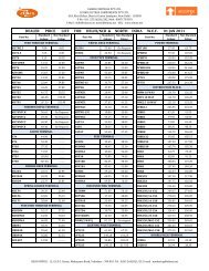
Ordering Option Table<br />
Dimensions<br />
Specify<br />
Model<br />
Accuracy<br />
Input<br />
voltage<br />
(in volts)<br />
Input<br />
current<br />
(in amps)<br />
PT<br />
Primary<br />
(in Volts)<br />
CT<br />
Primary<br />
(in Amps)<br />
Aux<br />
supply<br />
(in volts)<br />
Tamper<br />
cover<br />
Bezel : 96 x 96 mm<br />
Depth : 80 mm behind Bezel<br />
Panel cutout : 92 +0.5 x 92 +0.5 mm<br />
EM 5230<br />
CL 1.0<br />
110<br />
1<br />
33K<br />
100<br />
110<br />
CL 0.5<br />
415<br />
5<br />
11K<br />
1200<br />
240<br />
<strong>DM</strong> 5240<br />
CL 1.0<br />
CL 0.5<br />
110<br />
415<br />
1<br />
5<br />
415<br />
33K<br />
5<br />
200<br />
110<br />
240<br />
Note: One typical value for CT and PT primary is shown above. Meters can be supplied with<br />
other also.<br />
9mm additional space on both side of<br />
the meter inside the Panel<br />
Schneider Electric India Pvt. Ltd.<br />
44P Electronic City East Phase Hosur Road, Bangalore 560 100 INDIA<br />
P +91 80 3910 2730, F +91 80 3910 2735 E contact@conzerv.com<br />
Customer Care Centre: Toll-free numbers: 1800 180 1707, 1800 103 0011,<br />
General number: 0124 4222040, Email: in-care@in.schneider-electric.com