41 22 13.13-001 Bp 6 OPS Bridge Crane - Garney Construction
41 22 13.13-001 Bp 6 OPS Bridge Crane - Garney Construction
41 22 13.13-001 Bp 6 OPS Bridge Crane - Garney Construction
Create successful ePaper yourself
Turn your PDF publications into a flip-book with our unique Google optimized e-Paper software.
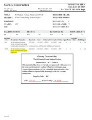
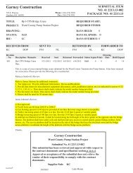
<strong>Garney</strong> <strong>Construction</strong><br />
785 E Warren<br />
Gardner, KS 66030<br />
Phone: 816-278-5950<br />
Fax: 816-278-5931<br />
SUBMITTAL ITEM<br />
O. <strong>41</strong> <strong>22</strong><strong>13.13</strong>-<strong>001</strong><br />
PACKAGE O: <strong>41</strong> <strong>22</strong><strong>13.13</strong><br />
TITLE:<br />
PROJECT:<br />
DRAWIG:<br />
STATUS:<br />
BIC:<br />
<strong>Bp</strong> 6 <strong>OPS</strong> <strong>Bridge</strong> <strong>Crane</strong><br />
Ward County Pump Station Project<br />
OPN<br />
FNI<br />
REQUIRED START:<br />
REQUIRED FIISH:<br />
DAYS HELD: 0<br />
DAYS ELAPSED: 1<br />
DAYS OVERDUE: 0<br />
RECEIVED FROM<br />
KC DOP<br />
SET TO<br />
FNI<br />
NL<br />
RETURED BY<br />
FNI NL<br />
FORWARDED TO<br />
KC DOP<br />
Revision<br />
o. Description / Remarks Received Sent Returned Forwarded Status Sepias Prints<br />
Drawing<br />
Date HeldElapsed<br />
<strong>001</strong> <strong>Bp</strong> 6 <strong>OPS</strong> <strong>Bridge</strong> <strong>Crane</strong> 5/21/2012 5/<strong>22</strong>/2012 OPN 0 0 0 1<br />
Please mark submittal RUSH.<br />
To whom it may concern:<br />
This submittal contains information and shop drawings pertaining to specification section <strong>41</strong> <strong>22</strong> <strong>13.13</strong>, <strong>Bridge</strong> <strong>Crane</strong>s.<br />
Please note:<br />
1. This submittal contains the crane components, shop drawings, and electrical components, but the electrical and control<br />
wiring schematics will be submitted under a separate cover at a later date.<br />
2. Factory test will be followed per section <strong>41</strong> <strong>22</strong> <strong>13.13</strong>-1.02.C<br />
3. Manufacturer's Representative for Startup and Testing will be provided per section <strong>41</strong> <strong>22</strong> <strong>13.13</strong>-1.02.D.<br />
If you have any questions or need any additional information please contact Luke Messer at 816-536-7187.<br />
Thanks,<br />
<strong>Garney</strong> <strong>Construction</strong><br />
Ward County Pump Station Project<br />
Submittal o. <strong>41</strong> <strong>22</strong><strong>13.13</strong>-<strong>001</strong><br />
This submittal has been reviewed and approved with respect to<br />
the contract documents and specification section<strong>41</strong> <strong>22</strong><strong>13.13</strong><br />
Approval or acceptance of the submittal does not relieve the<br />
vendor of their responsibility to comply with the contract<br />
documents.<br />
Supplier/Sub: KC<br />
Date: ______________ Reviewed by: _________________<br />
Expedition ®
Calculation number:<br />
DO120<strong>41</strong>701<br />
Printed by .................... PRGDOP<br />
Printing date: ............. 05/<strong>22</strong>/2012<br />
Printing time: ............ 7:<strong>22</strong> AM Page: 1 (2)<br />
CRANE DATA<br />
1 General<br />
<strong>Crane</strong> type ..............................................................................CXTD15-TON x 33.5ft Hol:23.38ft<br />
Span ..........................................................................................33'-6"<br />
<strong>Crane</strong> load (SWL) ...............................................................30 000 lbs<br />
Number of hoists ................................................................1 pc<br />
Hoist 1<br />
Trolley type ........................................................................Standard<br />
Hoist load ..........................................................................30 000 lbs<br />
Hoisting height .............................................................23'-4 1/2" [max 24'-7 1/4" ]<br />
Hoist type .........................................................................CXT60<strong>41</strong>0160P65FDD0F<br />
Hoist group ......................................................................FEM M5 (2m)<br />
Hoisting speed ..............................................................19/3.3 ft/min 2 - speed<br />
Trolley traversing speed ..............................................65 ft/min Stepless<br />
Weight of one hoist and trolley ..............................2 880 lbs<br />
Trolley rail gauge...............................................................5'-6 15/16"<br />
<strong>Crane</strong> use ................................................................................Indoor<br />
<strong>Crane</strong> group ...........................................................................CMAA C<br />
<strong>Bridge</strong> traveling group .....................................................FEM M5 (2m)<br />
<strong>Bridge</strong> traveling speed......................................................100 ft/min<br />
Stepless<br />
Dynamic coefficient for load .......................................1.15<br />
Dynamic coefficient dead load ...................................1.10<br />
<strong>Crane</strong> acceleration time..................................................4.7 s<br />
Weight of crane (with hoists) .......................................11 740 lbs<br />
Weight of crane bridge (without hoists) .................8 860 lbs<br />
Weight of one end carriage ...........................................1 120 lbs<br />
Weight of one crane traveling machinery .............40 lbs<br />
Weight of bridge panel ....................................................60 lbs<br />
Weight of one main girder ............................................2 900 lbs<br />
Weight of crane service platform ................................N/A<br />
Note! The maximum current of crane includes the starting current of hoisting motor(s)<br />
and nominal current of trolley and bridge traveling motors. The nominal current of<br />
crane includes the nominal current of hoisting, trolley and bridge motors. Maximum or<br />
nominal currents of crane do not include the currents of additional accessories, such as<br />
lamps, magnets etc.
Calculation number:<br />
DO120<strong>41</strong>701<br />
Printed by .................... PRGDOP<br />
Printing date: ............. 05/<strong>22</strong>/2012<br />
Printing time: ............ 7:<strong>22</strong> AM Page: 2 (2)<br />
Main girder type (Welded box) ...................................14.5/20.5/0.25/0.38/0.25/0.38-34.8<br />
Service platform type........................................................N/A<br />
Surface preparation / painting type ........................Standard / RAL1028<br />
2 Electrical<br />
Main voltage .........................................................................460 V /60 Hz<br />
Control voltage .....................................................................115 V<br />
Nominal power of crane .................................................26.9 hp<br />
Main fuse size at bridge panel ...................................50 A<br />
Maximum current of crane *) ........................................155.9 A<br />
Nominal current of crane *) ...........................................38.9 A<br />
Power factor at starting current .................................0.60<br />
Power factor at nominal current ...............................0.88<br />
Note! The maximum current of crane includes the starting current of hoisting motor(s)<br />
and nominal current of trolley and bridge traveling motors. The nominal current of<br />
crane includes the nominal current of hoisting, trolley and bridge motors. Maximum or<br />
nominal currents of crane do not include the currents of additional accessories, such as<br />
lamps, magnets etc.
Calculation number:<br />
DO120<strong>41</strong>701<br />
Printed by .................... PRGDOP<br />
Printing date: ............. 05/<strong>22</strong>/2012<br />
Printing time: ............ 7:<strong>22</strong> AM Page: 1 (2)<br />
COMPONENTS AND ADDITIONAL FEATURES DATA<br />
1 Selected components and additional features<br />
(Included in the component package)<br />
Electric hoist 1: 1 x CXT60<strong>41</strong>0160P65FDD0F<br />
- 1 pcs Overload protector (HS03)<br />
- 1 pcs Drum brake (HS07); STD<br />
- 1 pcs Mechanical overload device (LOA08)<br />
- 1 pcs Trolley travel inverter braking resistor type (FC02); STD<br />
End Carriages: 2 x ECN25-3264-H<strong>41</strong>383B0000-N<br />
- Joint: B-TOP-H_-STD-S<br />
- Buffer: D<strong>22</strong>40<br />
- 1 pcs End carriages with primer paint only (PAI05); S<br />
Traveling machinery: 2 x GES4B0PS2BOF06LA100-6400N<br />
<strong>Bridge</strong> panel: 1 x CRANELP6-1QQ400-76JE<br />
- 1 pcs 2-step limit switch, bridge traveling (slow+stop) (LIM12); YES<br />
- 1 pcs Stainless steel bridge control panel (PAN04)<br />
- 1 pcs <strong>Bridge</strong> travel inverter braking resistor type (FC03); STD<br />
Trolley speed control (Hoist 1): 1 x DYNADRIVE0<strong>22</strong>FXXTNS<br />
<strong>Bridge</strong> speed control: 1 x DYNADRIVE0<strong>22</strong>FXXTNS<br />
Trolley power supply [- festoon] package: 1 x QQSMD14M60P676102-<br />
- 1 pcs Sticker set (ST09); 4<br />
- 1 pcs Length of hoist cable free end to bridge panel(E1) (PS<strong>22</strong>); 7200<br />
- 1 pcs Length of hoist cable free end to hoist panel (E2) (PS23); 6200<br />
-AddNam (AddLm_Cod); AddFeaSubVar<br />
Push button station: 1 x PENDAX08-<strong>22</strong>21NC00-069P0
Calculation number: ... DO120<strong>41</strong>701<br />
Printed by ...................... PRGDOP<br />
Printing date: ................ 05/<strong>22</strong>/2012<br />
Printing time: ................. 7:<strong>22</strong> AM Page: 2 (2)<br />
- 1 pcs Plug-in connector for pendant cable (ELE16); PE3<br />
2 NOT selected components<br />
(NOT included in the component package)<br />
3 Local additional features<br />
(Supplied locally. NOT included in the component package)
Calculation number:<br />
DO120<strong>41</strong>701<br />
Printed by .................... PRGDOP<br />
Printing date: ............. 05/<strong>22</strong>/2012<br />
Printing time: ............ 7:21 AM Page: 1 (2)<br />
CRANE WHEEL LOAD DATA<br />
1 Wheel load drawing<br />
2 <strong>Crane</strong> information<br />
<strong>Crane</strong> type CXTD15-TON x 33.5ft Buffer type<br />
D<strong>22</strong>40<br />
Hol:23.38ft<br />
Span (Spa) 33'-6" Wheel base (Wb) 10'-4"<br />
Load (SWL) 30 000 lbs <strong>Crane</strong> rail in calculati ASCE40<br />
<strong>Crane</strong> group CMAA C Wheel groove 2 1/2"<br />
<strong>Crane</strong> speed 100 ft/min Guide Rol – wheel Dis 0"<br />
<strong>Crane</strong> weight 11 740 lbs <strong>Crane</strong> travel limit switc2-step<br />
3 Hoist information<br />
Hoist Hoist type Hoist group Hoisting speed<br />
Hoist 1 Main CXT60<strong>41</strong>0160P6 FEM M5 (2m) 19/3.3 ft/min<br />
Hoist 1 Aux<br />
4 Vertical wheel loads<br />
Wheel NR1 NR2 NR3 NR4<br />
Rmax Stc 18.1 kips 16.5 kips - -<br />
Rmin Stc - - 3.7 kips 3.6 kips<br />
Note! The inertia forces are acting on the crane structure only during acceleration<br />
and deceleration of the crane movement. Inertia forces and guiding forces do not act<br />
simultaneously. Guiding force S can also locate in wheel NR4.
Calculation number:<br />
DO120<strong>41</strong>701<br />
Printed by .................... PRGDOP<br />
Printing date: ............. 05/<strong>22</strong>/2012<br />
Printing time: ............ 7:21 AM Page: 2 (2)<br />
Rmax<br />
Dyn<br />
Rmin<br />
Dyn<br />
20.6 kips 18.7 kips - -<br />
- - 4.1 kips 4.0 kips<br />
5 Horizontal wheel loads (according to DIN <strong>41</strong>32 + 15018 and FEM)<br />
5.1 Inertia forces (from driving mechanisms) HM2 = 1.4 kips<br />
5.2 Max. Wheel loads along each crane runway Kr = 1.1 kips<br />
5.3 Buffer force for dimensioning the crane runway end stop Bf = 7 kips<br />
5.4 Forces coming from skewing<br />
5.4.1 Guiding (contact) force (S= HS2 + HS4) S = 5.5 kips<br />
5.4.2 Friction forces due to oblique travel HS2 = 4.5 kips HS4 = 1.0 kips<br />
Note! The inertia forces are acting on the crane structure only during acceleration<br />
and deceleration of the crane movement. Inertia forces and guiding forces do not act<br />
simultaneously. Guiding force S can also locate in wheel NR4.
Calculation number:<br />
DO120<strong>41</strong>701<br />
Printed by .................... PRGDOP<br />
Printing date: ............. 05/<strong>22</strong>/2012<br />
Printing time: ............ 7:19 AM Page: 1 (2)<br />
TROLLEY WHEEL LOAD DATA<br />
Hoist 1<br />
1 General<br />
Hoist load (SWL) ................................................................30 000 lbs<br />
Hoisting height .................................................................23'-4 1/2" [max 24'-7 1/4" ]<br />
Hoist type .............................................................................CXT60<strong>41</strong>0160P65FDD0F<br />
Hoist group .........................................................................FEM M5 (2m)<br />
Trolley traversing duty group ......................................FEM M5 (2m)<br />
Hoisting speed ...................................................................19/3.3 ft/min 2-speed<br />
Trolley traversing speed ..................................................65 ft/min Stepless<br />
Weight of hoist and trolley ...........................................2 880 lbs<br />
2 Wheel load drawing<br />
3 Wheel load data<br />
Distance between wheel centers (L15).....................4'-11"<br />
Trolley rail gauge (Gau__)..............................................5'-6 15/16"<br />
Static Wheel load (load + trolley / trolley only) (NR1)<br />
9 262 lbs / 857 lbs
Calculation number:<br />
DO120<strong>41</strong>701<br />
Printed by .................... PRGDOP<br />
Printing date: ............. 05/<strong>22</strong>/2012<br />
Printing time: ............ 7:19 AM Page: 2 (2)<br />
Static Wheel load (load + trolley / trolley only) (NR2)<br />
Static Wheel load (load + trolley / trolley only) (NR3)<br />
Static Wheel load (load + trolley / trolley only) (NR4)<br />
Dynamic Wheel load (load and trolley wgt.) (NR1) 10.6 kips<br />
Dynamic Wheel load (load and trolley wgt.) (NR2) 10.4 kips<br />
Dynamic Wheel load (load and trolley wgt.) (NR3) 8.4 kips<br />
Dynamic Wheel load (load and trolley wgt.) (NR4) 8.2 kips<br />
9 073 lbs / 554 lbs<br />
7 348 lbs / 893 lbs<br />
7 198 lbs / 577 lbs
Calculation number:<br />
DO120<strong>41</strong>701<br />
Printed by .................... PRGDOP<br />
Printing date: ............. 05/<strong>22</strong>/2012<br />
Printing time: ............ 7:21 AM Page: 1 (2)<br />
ELECTRICAL COMPONENT DATA<br />
1 General<br />
<strong>Crane</strong> type ..............................................................................CXTD15-TON x 33.5ft Hol:23.38ft<br />
<strong>Crane</strong> main / control voltage.......................................460 V /60 Hz / Control 115 V<br />
Nominal power of crane .................................................26.9 hp<br />
Maximum / nominal current of crane *) ................155.9 A / 38.9 A<br />
Power factor at starting / nominal current .........0.60 / 0.88<br />
2 <strong>Bridge</strong> panel<br />
<strong>Bridge</strong> panel type ...............................................................CRANELP6-1QQ400-76JE<br />
<strong>Bridge</strong> panel length / weight (preliminary)........3'-11" / 60 lbs<br />
Main fuse size at bridge panel ...................................50 A<br />
3 Hoist speed control<br />
Hoist 1<br />
Type MAIN.........................................................................2 – speed<br />
Control method / Location .........................................2SP / Trolley panel<br />
4 Trolley speed control<br />
Hoist 1<br />
Type ........................................................................................DYNADRIVE0<strong>22</strong>FXXTNS, stepless<br />
Control method / Location .........................................EP / Trolley panel<br />
Adjusted acceleration time .........................................3.6 s<br />
Nominal current margin ............................................1.4<br />
Maximum current margin .........................................1.4<br />
5 <strong>Bridge</strong> speed control<br />
Type ...........................................................................................DYNADRIVE0<strong>22</strong>FXXTNS, stepless<br />
Voltage ......................................................................................460 V<br />
Control method / Location ............................................EP / <strong>Bridge</strong> panel<br />
Adjusted acceleration time ............................................5.2 s<br />
Nominal current margin ...............................................1.6<br />
Maximum current margin ...........................................1.2
Calculation number:<br />
DO120<strong>41</strong>701<br />
Printed by .................... PRGDOP<br />
Printing date: ............. 05/<strong>22</strong>/2012<br />
Printing time: ............ 7:21 AM Page: 2 (2)<br />
6 Trolley power supply [festoon]<br />
Hoist 1<br />
Type ........................................................................................QQSMD14M60P676102-<br />
Hoist main power cable type .....................................FC0804 FLAT<br />
Distance between cable trolleys ...............................6'-0"<br />
Cable trolley type ............................................................KC-023571<br />
Free cable length at bridge panel end .................23'-7"<br />
Free cable length at hoist panel end ....................20'-4"<br />
Voltage drop of trolley power supply ....................
Calculation number:<br />
DO120<strong>41</strong>701<br />
Printed by .................... PRGDOP<br />
Printing date: ............. 05/<strong>22</strong>/2012<br />
Printing time: ............ 7:20 AM Page: 1 (2)<br />
MOTOR DATA<br />
1 General<br />
<strong>Crane</strong> type ..............................................................................CXTD15-TON x 33.5ft Hol:23.38ft<br />
Span ..........................................................................................33'-6"<br />
<strong>Crane</strong> load (SWL) ...............................................................30 000 lbs<br />
<strong>Crane</strong> voltage ........................................................................460 V<br />
2 Hoisting motor<br />
Hoist 1<br />
Motor code .......................................................................P6<br />
Motor type ........................................................................1 x MF13Z-106<br />
Synchronized speed ....................................................3 600 / 600 r/min<br />
Duty group ......................................................................FEM M5 (2m)<br />
Nominal power .............................................................24.1/4 hp<br />
Duty factor ......................................................................60 % ED<br />
Starting torque (High Speed) ..................................75.2 lbf-ft<br />
Starting current (High Speed) ................................149.0 A<br />
Nominal current (High Speed) ..............................32.0 A<br />
Power factor at starting current ...........................0.60<br />
Power factor at nominal current .........................0.88<br />
3 Trolley traversing motor<br />
Hoist 1<br />
Motor type ...........................................................................MF06LA20P<br />
Motor voltage .....................................................................261 V<br />
Number of motors ............................................................2 ps<br />
Synchronized speed .......................................................1 800 / r/min<br />
Nominal speed ..................................................................1 800 / r/min<br />
Duty group ..........................................................................FEM M5 (2m)<br />
Nominal power ................................................................0.5 hp<br />
Duty factor .........................................................................40 % ED<br />
Starting torque (High Speed) .....................................5.2 lbf-ft<br />
Starting current (High Speed) ...................................2.8 A<br />
Note! The supplied motor data plates have typically power and current values labeled<br />
for 40%ED (S3) use and hoisting motor for FEM M4 (1Am) duty. Therefore the data plate<br />
values might vary from the above-calculated actual values, which are based on the<br />
actual use and duty group of the crane.
Calculation number:<br />
DO120<strong>41</strong>701<br />
Printed by .................... PRGDOP<br />
Printing date: ............. 05/<strong>22</strong>/2012<br />
Printing time: ............ 7:20 AM Page: 2 (2)<br />
Nominal current (High Speed) .................................1.8 A<br />
4 <strong>Bridge</strong> traveling motor<br />
Motor type ................................................................................... MF06LA100<br />
Motor voltage.............................................................................. 380 V<br />
Number of motors .................................................................... 2 ps<br />
Synchronized speed ............................................................... 4 800 / r/min<br />
Nominal speed .......................................................................... 4 320 / r/min<br />
Duty group .................................................................................. FEM M5 (2m)<br />
Nominal power ......................................................................... 0.8 hp<br />
Duty factor .................................................................................. 40 % ED<br />
Starting torque (High Speed) ............................................. 4.1 lbf-ft<br />
Starting current (High Speed) ........................................... 3.1 A<br />
Nominal current (High Speed) ......................................... 1.6 A<br />
Note! The supplied motor data plates have typically power and current values labeled<br />
for 40%ED (S3) use and hoisting motor for FEM M4 (1Am) duty. Therefore the data plate<br />
values might vary from the above-calculated actual values, which are based on the<br />
actual use and duty group of the crane.
Calculation number:<br />
DO120<strong>41</strong>701<br />
Printed by .................... PRGDOP<br />
Printing date: ............. 05/<strong>22</strong>/2012<br />
Printing time: ............ 7:21 AM Page: 1 (2)<br />
END CARRIAGE AND TRAVELING MACHINERY DATA<br />
1 General<br />
<strong>Crane</strong> type ..............................................................................CXTD15-TON x 33.5ft Hol:23.38ft<br />
Span ..........................................................................................33'-6"<br />
<strong>Crane</strong> load (SWL) ...............................................................30 000 lbs<br />
2 End carriage<br />
End carriage type ...............................................................ECN25-3264-H<strong>41</strong>383B0000-N<br />
<strong>Bridge</strong> traveling group .....................................................FEM M5 (2m)<br />
Maximum static wheel load ........................................18.1 kips<br />
Maximum dynamic wheel load .................................20.6 kips<br />
Maximum wheel load along rail ..............................1.1 kips<br />
CMAA Equivalent durability wheel load - Pe ..13 950 lbs<br />
CMAA Guide for max. durability wheel load - P 16 <strong>41</strong>6 lbs > Pe<br />
Wheel Hardness ...................................................................280.0 BHN<br />
Runway rail type ..............................................................ASCE40<br />
Minimum allowed wheel diameter ..........................9 5/8"<br />
Calculated bearing life time ........................................42 620 h<br />
Bending stress of end carriage .....................................12.3 ksi<br />
Deflection of end carriage .............................................1/16"<br />
Wheel groove .........................................................................2 1/2"<br />
Joint type ...............................................................................B-TOP-H_-STD-S<br />
Buffer type .............................................................................D<strong>22</strong>40<br />
Buffer length ........................................................................2 5/8"<br />
Buffer diameter ...................................................................3 1/8"<br />
Buffer center from top of crane rail .........................5 7/8"<br />
3 Traveling machinery<br />
Machinery type ...................................................................GES4B0PS2BOF06LA100-6400N<br />
Number of traveling machinery ................................2 pc<br />
Nominal power of motor (High / Low Speed) ......0.8 hp
Calculation number:<br />
DO120<strong>41</strong>701<br />
Printed by .................... PRGDOP<br />
Printing date: ............. 05/<strong>22</strong>/2012<br />
Printing time: ............ 7:21 AM Page: 2 (2)<br />
Synchronized speed of motor (High / Low Speed) 4 800 / r/min<br />
Nominal speed of motor (High / Low Speed) .......4 320 / r/min<br />
Nominal torque of motor (High Speed) ...................1.0 lbf-ft<br />
Gear ratio ...............................................................................107.8<br />
Nominal bridge speed (High / Low Speed)............100 ft/min<br />
Practical bridge speed (High Speed) .........................106.0 ft/min<br />
Stepless<br />
Acceleration time ...............................................................5.2 s (< 4.7 s)<br />
Electrical braking distance ..........................................5'-5 3/16"<br />
Mechanical braking distance ......................................2'-3"<br />
Thermal loading per motor ..........................................0.67 hp<br />
Number of starts per hour .............................................N/A<br />
Torque margin .....................................................................1.84 (>=1)<br />
Power margin .......................................................................1.23 (>=1)
Calculation number:<br />
DO120<strong>41</strong>701<br />
Printed by .................... PRGDOP<br />
Printing date: ............. 05/<strong>22</strong>/2012<br />
Printing time: ............ 7:20 AM Page: 1 (6)<br />
MAIN GIRDER DATA<br />
1 Main girder data<br />
<strong>Crane</strong> type ..............................................................................CXTD15-TON x 33.5ft Hol:23.38ft<br />
Main girder type code (Welded box) ........................14.5/20.5/0.25/0.38/0.25/0.38-34.8<br />
Flange width (B__)..............................................................1'-2 1/2"<br />
Web height (H__) .................................................................1'-8 1/2"<br />
Thickness of web (T1_) (item 2) ..................................1/4" (Material: 34.8 ksi)<br />
Thickness of web (T3_) (item 3) ..................................1/4" (Material: 34.8 ksi)<br />
Thickness of bottom flange (T2_) (item 4) .............3/8" (Material: 34.8 ksi)<br />
Thickness of top flange (T4_) (item 1) .....................3/8" (Material: 34.8 ksi)<br />
Thickness of web strengthening plates (T7_) (item 9) 1/4" (Material: 34.8 ksi)<br />
Actual web height at girder end (JoiMinWebHgtT1_) 1'-8 7/8"<br />
Min. web height at girder end (JoiMinWebHgtT1_) 7 7/8" (with T1-plate)<br />
Min. web height at girder end (JoiMinWebHgtT7_) 7 7/8" (with T7 plate)<br />
Thickness of diaphragms (DiaTd_) (item 5) .......1/4" (34.8 ksi)<br />
Distance between diaphragms (DiaMod) ...............6'-0"<br />
Flange flaps (F1_,F2_,F3_,F4_).......................................2" / 2" / 2" / 2"<br />
Stiffener type (items 6 and 7) ......................................<br />
Stiffener distance from top flange (StiH1_,2_,3_,4_) 0" / 0" / 0" / 0"<br />
Trolley rail type (item 10) ............................................2"x1"<br />
Trolley end stop distance from runway rail center Panel s.: 0" / Non panel s.:<br />
3/16"<br />
2 Main girder dimensions
Calculation number:<br />
DO120<strong>41</strong>701<br />
Printed by .................... PRGDOP<br />
Printing date: ............. 05/<strong>22</strong>/2012<br />
Printing time: ............ 7:20 AM Page: 2 (6)<br />
Note! The shape of girder end is not to scale and not according to crane layout. If the<br />
stiffener distance is "0", the stiffener is not needed.
Calculation number:<br />
DO120<strong>41</strong>701<br />
Printed by .................... PRGDOP<br />
Printing date: ............. 05/<strong>22</strong>/2012<br />
Printing time: ............ 7:20 AM Page: 3 (6)<br />
3 Main girder welding<br />
Main girder welding according to .............................CSW01_1B1 – standard crane welding<br />
Longitudinal welding of web-top plate under rail Full penetration weld<br />
Trolley rail welding .........................................................Step weld - Indoor use<br />
4 Main girder (and service platform) weights and area<br />
Number of main girders .................................................2 ps<br />
Weight of one main girder / length unit...............85 lbs/ft<br />
Weight of one main girder ............................................2 900 lbs<br />
Weight of crane service platform ................................N/A<br />
Service platform type........................................................N/A<br />
Surface area of main girder .........................................510 ft²<br />
Surface area of crane service platform ...................N/A<br />
5 Calculated values<br />
Vertical deflection (load and trolley) ......................7/16" < 7/16"<br />
Vertical deflection (overall)..........................................15/32" < 1 7/32"<br />
Horizontal deflection .......................................................1/16" < 13/16"<br />
Vertical frequency without load ................................11.40 > 2.00 Hz<br />
Vertical frequency with load .......................................4.60 > 2.51 Hz<br />
Horizontal frequency .......................................................9.1 > 1.80 Hz<br />
Max allowed buffer force ...............................................116.9 kips<br />
Fatigue calculation (Point 1) ......................................0.40
Calculation number:<br />
DO120<strong>41</strong>701<br />
Printed by .................... PRGDOP<br />
Printing date: ............. 05/<strong>22</strong>/2012<br />
Printing time: ............ 7:20 AM Page: 4 (6)<br />
Distance of Y-Axis .............................................................7 11/16"<br />
Moment of inertia IXX .....................................................1 794 in^4<br />
Moment of inertia IYY ......................................................535 in^4<br />
Note! The surface areas include the multipliers for painting wastage (i.e. the<br />
area is not actual area if the wastage multiplier is not =1). The surface area of<br />
main girder includes the area of end carriages.
Calculation number:<br />
DO120<strong>41</strong>701<br />
Printed by .................... PRGDOP<br />
Printing date: ............. 05/<strong>22</strong>/2012<br />
Printing time: ............ 7:20 AM Page: 5 (6)<br />
6 Calculated values<br />
<strong>Crane</strong> type ..............................................................................CXTD15-TON x 33.5ft Hol:23.38ft<br />
Main girder type code (Welded box) ........................14.5/20.5/0.25/0.38/0.25/0.38-34.8<br />
Points Normal Shear Flange X Flange Z Equivalen Allowed Eq.<br />
t<br />
1 -9.5 -1.6 -10.3 10.1 20.9<br />
2 13.3 1.1 13.3 20.9<br />
3 11.3 0.4 11.3 20.9<br />
4 -11.4 -0.2 11.4 20.9<br />
5<br />
6<br />
7<br />
8<br />
All values in ksi<br />
7 Stress calculation points<br />
Single Girder<br />
PROFILE<br />
Double<br />
Girder<br />
Single<br />
Girder<br />
BOX<br />
Double<br />
Girder<br />
BOX
Calculation number:<br />
DO120<strong>41</strong>701<br />
Printed by .................... PRGDOP<br />
Printing date: ............. 05/<strong>22</strong>/2012<br />
Printing time: ............ 7:20 AM Page: 6 (6)
CLDB01B2<br />
LOWEST POINT OF ROOF OR OTHER EQUIPMENT (LIGHTS...)<br />
11’-11 1/4" 28’-8 1/2"<br />
5’-4 1/2"<br />
5’-1/2"<br />
10’-4"<br />
23’-4"<br />
5’-6 7/8"<br />
2’-11 5/8"<br />
Min. 8 1/2"<br />
24’-5 3/8" 1’-10 1/4"<br />
A<br />
A<br />
3’-3"<br />
23’-1"<br />
CXT60<strong>41</strong>0160P6<br />
CABLE CHANNEL<br />
5’-0" 4"<br />
23’-4 1/2"<br />
Min. 2"<br />
Min. 1 1/8"<br />
15 Ton<br />
Min. 3’-0" Min. 3’-0"<br />
33’-6"<br />
Max. 1’-1 3/4"<br />
RAIL ASCE40<br />
Max. 5 7/8"<br />
3’-4 7/8"<br />
RAIL ASCE40<br />
Min. 8 1/2"<br />
MAX. STATIC WHEEL LOAD 18.1 kips<br />
ECN25-3264-H<strong>41</strong>383B0000-N<br />
INDICATE NORTH DIRECTION<br />
IMPORTANT<br />
TECHNICAL DATA<br />
MODIFY, IF REQUIRED, AND APPROVE ONE<br />
SET OF PRINTS AND RETURN WITHIN TWO<br />
WEEKS OF DRAWING DATE. ANY DELAY IN<br />
RETURNING AN APPROVED PRINT MAY MEAN<br />
A DELAY IN SHIPMENT.<br />
APPROVED______________________<br />
BY____________________________<br />
DATE__________________________<br />
= =<br />
LOAD........................................<br />
SPAN........................................<br />
LIFTING HEIGHT.....................<br />
HOISTING SPEED...................<br />
TROLLEY SPEED....................<br />
BRIDGE SPEED......................<br />
WEIGHT OF TROLLEY............<br />
WEIGHT OF BRIDGE..............<br />
POWER SUPPLY.....................<br />
CRANE GROUP.......................<br />
PART LIST<br />
A-A<br />
4"<br />
4"<br />
2’-10"<br />
3 1/4"<br />
5 7/8"<br />
15 Ton<br />
33’-6"<br />
23’-4 1/2"<br />
19/3.3 ft/min 2-SPEED<br />
65 ft/min STEPLESS<br />
100 ft/min STEPLESS<br />
2880 lbs<br />
8860 lbs<br />
460 V / 115 V / 60 Hz<br />
CMAA C<br />
34’-4 5/8"<br />
CUSTOMER ORGANIZES SAFE<br />
PLATFORM FOR CRANE SERVICE<br />
DRAWING NOT IN SCALE<br />
DOP/PRG<br />
4/17/2012 15 Ton CXTD <strong>Crane</strong><br />
<strong>Garney</strong> <strong>Construction</strong><br />
Gardner<br />
DO120<strong>41</strong>701


