

PIC12F683 Data Sheet - Microchip
PIC12F683 Data Sheet - Microchip
PIC12F683 Data Sheet - Microchip

Create successful ePaper yourself
Turn your PDF publications into a flip-book with our unique Google optimized e-Paper software.
<strong>PIC12F683</strong><br />
11.1 Capture Mode<br />
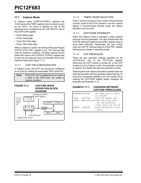
In Capture mode, CCPR1H:CCPR1L captures the<br />
16-bit value of the TMR1 register when an event occurs<br />
on pin CCP1. An event is defined as one of the<br />
following and is configured by the CCP1M bits of<br />
the CCP1CON register:<br />
• Every falling edge<br />
• Every rising edge<br />
• Every 4th rising edge<br />
• Every 16th rising edge<br />
When a capture is made, the Interrupt Request Flag bit<br />
CCP1IF of the PIR1 register is set. The interrupt flag<br />
must be cleared in software. If another capture occurs<br />
before the value in the CCPR1H, CCPR1L register pair<br />
is read, the old captured value is overwritten by the new<br />
captured value (see Figure 11-1).<br />
11.1.1 CCP1 PIN CONFIGURATION<br />
In Capture mode, the CCP1 pin should be configured<br />
as an input by setting the associated TRIS control bit.<br />
Note:<br />
FIGURE 11-1:<br />
CCP1<br />
pin<br />
If the CCP1 pin is configured as an output,<br />
a write to the GPIO port can cause a<br />
capture condition.<br />
Prescaler<br />
÷ 1, 4, 16<br />
and<br />
Edge Detect<br />
CAPTURE MODE<br />
OPERATION BLOCK<br />
DIAGRAM<br />
Set Flag bit CCP1IF<br />
(PIR1 register)<br />
CCP1CON<br />
System Clock (FOSC)<br />
Capture<br />
Enable<br />
CCPR1H<br />
TMR1H<br />
CCPR1L<br />
TMR1L<br />
11.1.2 TIMER1 MODE SELECTION<br />
Timer1 must be running in Timer mode or Synchronized<br />
Counter mode for the CCP module to use the capture<br />
feature. In Asynchronous Counter mode, the capture<br />
operation may not work.<br />
11.1.3 SOFTWARE INTERRUPT<br />
When the Capture mode is changed, a false capture<br />
interrupt may be generated. The user should keep the<br />
CCP1IE interrupt enable bit of the PIE1 register clear to<br />
avoid false interrupts. Additionally, the user should<br />
clear the CCP1IF interrupt flag bit of the PIR1 register<br />
following any change in operating mode.<br />
11.1.4 CCP PRESCALER<br />
There are four prescaler settings specified by the<br />
CCP1M bits of the CCP1CON register.<br />
Whenever the CCP module is turned off, or the CCP<br />
module is not in Capture mode, the prescaler counter<br />
is cleared. Any Reset will clear the prescaler counter.<br />
Switching from one capture prescaler to another does not<br />
clear the prescaler and may generate a false interrupt. To<br />
avoid this unexpected operation, turn the module off by<br />
clearing the CCP1CON register before changing the<br />
prescaler (see Example 11-1).<br />
EXAMPLE 11-1:<br />
CHANGING BETWEEN<br />
CAPTURE PRESCALERS<br />
BANKSEL CCP1CON ;Set Bank bits to point<br />
;to CCP1CON<br />
CLRF CCP1CON ;Turn CCP module off<br />
MOVLW NEW_CAPT_PS ;Load the W reg with<br />
; the new prescaler<br />
; move value and CCP ON<br />
MOVWF CCP1CON ;Load CCP1CON with this<br />
; value<br />
DS41211D-page 76<br />
© 2007 <strong>Microchip</strong> Technology Inc.


