PIC12F683 Data Sheet - Microchip
PIC12F683 Data Sheet - Microchip
PIC12F683 Data Sheet - Microchip
Create successful ePaper yourself
Turn your PDF publications into a flip-book with our unique Google optimized e-Paper software.
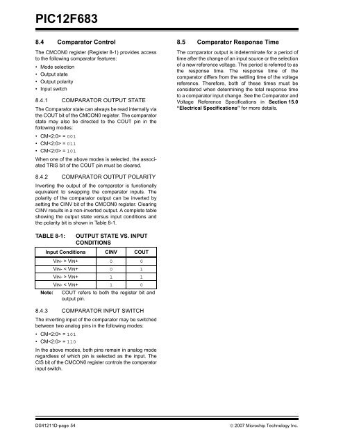
<strong>PIC12F683</strong><br />
8.4 Comparator Control<br />
The CMCON0 register (Register 8-1) provides access<br />
to the following comparator features:<br />
• Mode selection<br />
• Output state<br />
• Output polarity<br />
• Input switch<br />
8.4.1 COMPARATOR OUTPUT STATE<br />
The Comparator state can always be read internally via<br />
the COUT bit of the CMCON0 register. The comparator<br />
state may also be directed to the COUT pin in the<br />
following modes:<br />
• CM = 001<br />
• CM = 011<br />
• CM = 101<br />
When one of the above modes is selected, the associated<br />
TRIS bit of the COUT pin must be cleared.<br />
8.5 Comparator Response Time<br />
The comparator output is indeterminate for a period of<br />
time after the change of an input source or the selection<br />
of a new reference voltage. This period is referred to as<br />
the response time. The response time of the<br />
comparator differs from the settling time of the voltage<br />
reference. Therefore, both of these times must be<br />
considered when determining the total response time<br />
to a comparator input change. See the Comparator and<br />
Voltage Reference Specifications in Section 15.0<br />
“Electrical Specifications” for more details.<br />
8.4.2 COMPARATOR OUTPUT POLARITY<br />
Inverting the output of the comparator is functionally<br />
equivalent to swapping the comparator inputs. The<br />
polarity of the comparator output can be inverted by<br />
setting the CINV bit of the CMCON0 register. Clearing<br />
CINV results in a non-inverted output. A complete table<br />
showing the output state versus input conditions and<br />
the polarity bit is shown in Table 8-1.<br />
TABLE 8-1:<br />
OUTPUT STATE VS. INPUT<br />
CONDITIONS<br />
Input Conditions CINV COUT<br />
VIN- > VIN+ 0 0<br />
VIN- < VIN+ 0 1<br />
VIN- > VIN+ 1 1<br />
VIN- < VIN+ 1 0<br />
Note: COUT refers to both the register bit and<br />
output pin.<br />
8.4.3 COMPARATOR INPUT SWITCH<br />
The inverting input of the comparator may be switched<br />
between two analog pins in the following modes:<br />
• CM = 101<br />
• CM = 110<br />
In the above modes, both pins remain in analog mode<br />
regardless of which pin is selected as the input. The<br />
CIS bit of the CMCON0 register controls the comparator<br />
input switch.<br />
DS41211D-page 54<br />
© 2007 <strong>Microchip</strong> Technology Inc.


