

PIC12F683 Data Sheet - Microchip
PIC12F683 Data Sheet - Microchip
PIC12F683 Data Sheet - Microchip

You also want an ePaper? Increase the reach of your titles
YUMPU automatically turns print PDFs into web optimized ePapers that Google loves.
<strong>PIC12F683</strong><br />
5.0 TIMER0 MODULE<br />
The Timer0 module is an 8-bit timer/counter with the<br />
following features:<br />
• 8-bit timer/counter register (TMR0)<br />
• 8-bit prescaler (shared with Watchdog Timer)<br />
• Programmable internal or external clock source<br />
• Programmable external clock edge selection<br />
• Interrupt on overflow<br />
Figure 5-1 is a block diagram of the Timer0 module.<br />
5.1 Timer0 Operation<br />
When used as a timer, the Timer0 module can be used<br />
as either an 8-bit timer or an 8-bit counter.<br />
5.1.1 8-BIT TIMER MODE<br />
When used as a timer, the Timer0 module will<br />
increment every instruction cycle (without prescaler).<br />
Timer mode is selected by clearing the T0CS bit of the<br />
OPTION register to ‘0’.<br />
When TMR0 is written, the increment is inhibited for<br />
two instruction cycles immediately following the write.<br />
Note:<br />
The value written to the TMR0 register can<br />
be adjusted, in order to account for the two<br />
instruction cycle delay when TMR0 is<br />
written.<br />
5.1.2 8-BIT COUNTER MODE<br />
When used as a counter, the Timer0 module will<br />
increment on every rising or falling edge of the T0CKI<br />
pin. The incrementing edge is determined by the T0SE<br />
bit of the OPTION register. Counter mode is selected by<br />
setting the T0CS bit of the OPTION register to ‘1’.<br />
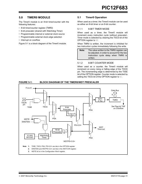
FIGURE 5-1:<br />
BLOCK DIAGRAM OF THE TIMER0/WDT PRESCALER<br />
FOSC/4<br />
T0CKI<br />
pin<br />
T0SE<br />
0<br />
1<br />
T0CS<br />
0<br />
1<br />
8-bit<br />
Prescaler<br />
1<br />
0<br />
PSA<br />
Sync<br />
2 Tcy<br />
<strong>Data</strong> Bus<br />
8<br />
TMR0<br />
Set Flag bit T0IF<br />
on Overflow<br />
WDTE<br />
SWDTEN<br />
31 kHz<br />
INTOSC<br />
Watchdog<br />
Timer<br />
PSA<br />
16-bit<br />
Prescaler<br />
16<br />
8<br />
PS<br />
1<br />
0<br />
PSA<br />
WDT<br />
Time-out<br />
WDTPS<br />
Note 1: T0SE, T0CS, PSA, PS are bits in the OPTION register.<br />
2: SWDTEN and WDTPS are bits in the WDTCON register.<br />
3: WDTE bit is in the Configuration Word register.<br />
© 2007 <strong>Microchip</strong> Technology Inc. DS41211D-page 41


