

PIC12F683 Data Sheet - Microchip
PIC12F683 Data Sheet - Microchip
PIC12F683 Data Sheet - Microchip

Create successful ePaper yourself
Turn your PDF publications into a flip-book with our unique Google optimized e-Paper software.
<strong>PIC12F683</strong><br />
3.4.4 EXTERNAL RC MODES<br />
The external Resistor-Capacitor (RC) modes support<br />
the use of an external RC circuit. This allows the<br />
designer maximum flexibility in frequency choice while<br />
keeping costs to a minimum when clock accuracy is not<br />
required. There are two modes: RC and RCIO.<br />
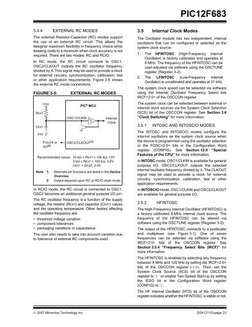
In RC mode, the RC circuit connects to OSC1.<br />
OSC2/CLKOUT outputs the RC oscillator frequency<br />
divided by 4. This signal may be used to provide a clock<br />
for external circuitry, synchronization, calibration, test<br />
or other application requirements. Figure 3-5 shows<br />
the external RC mode connections.<br />
FIGURE 3-5:<br />
REXT<br />
CEXT<br />
VSS<br />
VDD<br />
FOSC/4 or<br />
I/O (2)<br />
EXTERNAL RC MODES<br />
OSC1/CLKIN<br />
PIC ® MCU<br />
OSC2/CLKOUT (1)<br />
Internal<br />
Clock<br />
Recommended values: 10 kΩ ≤ REXT ≤ 100 kΩ, 20 pF, 2-5V<br />
Note 1: Alternate pin functions are listed in the Device<br />
Overview.<br />
2: Output depends upon RC or RCIO clock mode.<br />
In RCIO mode, the RC circuit is connected to OSC1.<br />
OSC2 becomes an additional general purpose I/O pin.<br />
The RC oscillator frequency is a function of the supply<br />
voltage, the resistor (REXT) and capacitor (CEXT) values<br />
and the operating temperature. Other factors affecting<br />
the oscillator frequency are:<br />
• threshold voltage variation<br />
• component tolerances<br />
• packaging variations in capacitance<br />
The user also needs to take into account variation due<br />
to tolerance of external RC components used.<br />
3.5 Internal Clock Modes<br />
The Oscillator module has two independent, internal<br />
oscillators that can be configured or selected as the<br />
system clock source.<br />
1. The HFINTOSC (High-Frequency Internal<br />
Oscillator) is factory calibrated and operates at<br />
8 MHz. The frequency of the HFINTOSC can be<br />
user-adjusted via software using the OSCTUNE<br />
register (Register 3-2).<br />
2. The LFINTOSC (Low-Frequency Internal<br />
Oscillator) is uncalibrated and operates at 31 kHz.<br />
The system clock speed can be selected via software<br />
using the Internal Oscillator Frequency Select bits<br />
IRCF of the OSCCON register.<br />
The system clock can be selected between external or<br />
internal clock sources via the System Clock Selection<br />
(SCS) bit of the OSCCON register. See Section 3.6<br />
“Clock Switching” for more information.<br />
3.5.1 INTOSC AND INTOSCIO MODES<br />
The INTOSC and INTOSCIO modes configure the<br />
internal oscillators as the system clock source when<br />
the device is programmed using the oscillator selection<br />
or the FOSC bits in the Configuration Word<br />
register (CONFIG). See Section 12.0 “Special<br />
Features of the CPU” for more information.<br />
In INTOSC mode, OSC1/CLKIN is available for general<br />
purpose I/O. OSC2/CLKOUT outputs the selected<br />
internal oscillator frequency divided by 4. The CLKOUT<br />
signal may be used to provide a clock for external<br />
circuitry, synchronization, calibration, test or other<br />
application requirements.<br />
In INTOSCIO mode, OSC1/CLKIN and OSC2/CLKOUT<br />
are available for general purpose I/O.<br />
3.5.2 HFINTOSC<br />
The High-Frequency Internal Oscillator (HFINTOSC) is<br />
a factory calibrated 8 MHz internal clock source. The<br />
frequency of the HFINTOSC can be altered via<br />
software using the OSCTUNE register (Register 3-2).<br />
The output of the HFINTOSC connects to a postscaler<br />
and multiplexer (see Figure 3-1). One of seven<br />
frequencies can be selected via software using the<br />
IRCF bits of the OSCCON register. See<br />
Section 3.5.4 “Frequency Select Bits (IRCF)” for<br />
more information.<br />
The HFINTOSC is enabled by selecting any frequency<br />
between 8 MHz and 125 kHz by setting the IRCF<br />
bits of the OSCCON register ≠ 000. Then, set the<br />
System Clock Source (SCS) bit of the OSCCON<br />
register to ‘1’ or enable Two-Speed Start-up by setting<br />
the IESO bit in the Configuration Word register<br />
(CONFIG) to ‘1’.<br />
The HF Internal Oscillator (HTS) bit of the OSCCON<br />
register indicates whether the HFINTOSC is stable or not.<br />
© 2007 <strong>Microchip</strong> Technology Inc. DS41211D-page 23


