TYPE 34200 STOCHASTICAL ANALVSER
TYPE 34200 STOCHASTICAL ANALVSER
TYPE 34200 STOCHASTICAL ANALVSER

You also want an ePaper? Increase the reach of your titles
YUMPU automatically turns print PDFs into web optimized ePapers that Google loves.
SOclctY~b k.é~.tf-:<br />
-+::r\,( -FL(~- ~ll.<br />
~lA zoo<br />
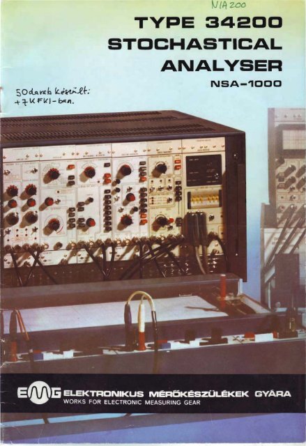
<strong>TYPE</strong> <strong>34200</strong><br />
STO,CHASTICAL<br />
<strong>ANALVSER</strong><br />
NSA-1000
<strong>TYPE</strong><br />
TYP<br />
346 O<br />
LVSE<br />
"-'<br />
l-ivtta, ,v)~{ .g_+ &tt"'cl -.zeti: 0 JA:-..w.l.J.te>t.~~<br />
( c'j_ "'1..;,.... ' -<br />
E ...-1 {.:.- ,.,...,~ ,,-fr;rrr S../l t!;~V'í.o~ · ~ , ........ t<br />
( ~ 7 J<br />
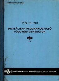
The Type 34 200 STO CHASTICAL ANALYSER ~ /; !'('{ 1 .)<br />
BASIC ASSEM BLY is a universol equipment for j-eV>.(-(<br />
testing rando m signals. Since, however, the r<br />
basic a ssembly will accommodate measuring ~ { ~\.'i~<br />
unit s other than the four basic ones, a new<br />
stochastical analyser is obtained, which offers<br />
a lorger number of facilities. Moreover, throug h<br />
o combination of the additiono l measuring units,<br />
setups optimolly suited to the actual measurement<br />
task will be obtained. The basic assembly<br />
can be used above ali in the follawing functions:<br />
auto-correlation<br />
cross-correlation<br />
cross-correlation (voltage-pulse)<br />
multi-channel signal averaging<br />
pulse rate time distribution<br />
time interval distribution<br />
omplitude distribution<br />
amplitude density<br />
signal mean and rrns values<br />
digital filtering<br />
pseudo-ro n dom sig na l generation<br />
system identification by pseudo-random<br />
sig no ls<br />
continuous manitoring or single onolysis<br />
generotion of digital sine, cosine, sowtooth<br />
sig no ls.<br />
The individuol odditional units will add the follawing<br />
functions to the above ones.<br />
FOURIER TRA SFO M<br />
E-640<br />
FOURIER TRANSFORMER<br />
real or imoginory port of lineor spectrum<br />
outo-power density function<br />
real or imoginory port of cross-power density<br />
function<br />
multiplication with window function (rectangulor,<br />
Honning, Bortlett)<br />
logarithmic Y output, too<br />
PE 3 67<br />
Dl IT L INTE<br />
Z- 75<br />
CE<br />
MONITOR<br />
visual observotion ond value estimation of<br />
input and output signals<br />
oncitlory for hondling ond servicing the peripherals<br />
.. off-crote" functioning (only +5.8 V/3,5 A).<br />
DIGITAL INTERFACE<br />
readout of chonne11 number and channel<br />
content of basic assembly<br />
readout of channel number ond channel<br />
content of Fourier transforrner<br />
continuous data readout within preselected<br />
limits<br />
interface to printer, tope punch, teletype<br />
optional (under development) interface to<br />
Type 666 programmable colculator
The equipment has been designed with the objective<br />
of providing a range of parameters as<br />
wide as possible, enabling many different types<br />
of measurement. The time schole of 100 ns to<br />
1 s, a resolution of about 1 °/ 0 (corresponding to<br />
100 channels), its facility of continuous manitoring<br />
- ali ore valuable features suiting the<br />
equipment to very wide applications in the<br />
measurements of stochastic signals. The equipment<br />
is a signal analyser ernplaying 100 digital<br />
channels, a storage capacity of 20 bits/ channel,<br />
performing aU computations simultaneously<br />
with the measurement. The basic as·<br />
sembly does not include a result display, but<br />
it can be attached to any conventional type of<br />
oscilloscope or XV plotter. Furthermore, the<br />
principel signals can be obtained from connectors.<br />
The resuhs can be read out at any frequene-y<br />
even during the measurement. ln addition<br />
to the conventional integreting-type averaging<br />
(single analysis), "forgetting" type integration<br />
(continuous monitoring) is also feasible. Both<br />
the number of averagings and the " forgetting"<br />
time constant ore variable over a wide range.<br />
The equipment can be used for the onolysis of<br />
continuous signals (AC or DC) and pulses. The<br />
width of its time channels can be selected between<br />
100 ns and 1 s (in correlation modes);<br />
thus it is equally suitable for the investigatien<br />
of very fast and very slow processes. ln amplitude<br />
analyses, the maximum sampling freque n<br />
ey is 5 kHz (otherwise 0.5 M Hz). The f unction<br />
generator provides digitaily generated sin, cos,<br />
pseudo-random and sawtooth sionals with<br />
frequencies adjustable over wide limits. The<br />
time functions of the basic assembly in multichannel<br />
signal averaging and correlation modes<br />
e-an be studied by aid of the Fourier transforrner<br />
in the frequency range, too. For a better<br />
i'llustration, the number of frequency pointscan<br />
be increased. Thus, tagether with the cycle time,<br />
the frequency resolütion can be varied over<br />
wide limits (from 1.25 mHz to 100 kHz). Focil1-<br />
ties ore provided for using time w indows other<br />
then the square-form, vis. multiplication by<br />
Honning and Bartlett weighting function. The<br />
real or the imaginary ports of the functions<br />
within the particulor range can be fo rrned in<br />
succession. Like in the basic a ssembly, the data<br />
outputs deliver analog as weil as d igita l signals<br />
moreover, the analog Y output can be switched<br />
over to logarithmic display, too. The Manitor<br />
unit performs mainly ancillary functions -visual<br />
observation of signals, the estimation of their<br />
values, setting the test setup, facilitating a servicing<br />
and handfing of peripherals (e. g. the use<br />
of Z modulation at peak searching}. Plugged in<br />
alternatively, the M anitor and the D igital Interface<br />
will take over the manitoring function of<br />
the power supply. IM PORTANTI The Manitor is<br />
suitable for "off·crate" functioning, too, only a<br />
power supply of +5,8 V/3,5 A is required. The<br />
Digital Interface enables the variaus functions<br />
(recorded by the basic assembly) and, in expanded<br />
configuration, the frequency spectra<br />
(provided by the Fourier transformer) to be displayed<br />
digitaily or recorded on o tape punch,<br />
o printer or teletype - of course, either for o<br />
given point o r for a ny arbitrary section.<br />
GENERAl SPECIFICATIONS OF THE<br />
BASIC ASSEMBLY<br />
mains data : voltage 220 V ± 10 Ofo<br />
(127 or 110 V by re-connection)<br />
frequency : 50/60 Hz<br />
power consumption: 250 VA<br />
- dimensions: height 316 mm<br />
widttl 505 mm<br />
d epth 600 mm<br />
weight : 36 kg<br />
warm -up time : 15 minutes
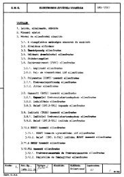
o HE IC S E BLV<br />
@<br />
Cabinet<br />
C rate (wi red frame)<br />
Front panel covering two blank ponels<br />
(i<br />
CE,<br />
0<br />
0<br />
Measuring uni ts :<br />
type 34 630 Sam pl ing unit NE-630<br />
type 34 631 1Processor NE-631<br />
type 34 632 Mulii-channel integretor NE-632<br />
type 34 633 Function generator NE-633<br />
IllUllliUl IUlfill IIIIC AlUilU<br />
"" lll·-<br />
+mn<br />
1111 llllllliT<br />
l \<br />
type<br />
®<br />
34 252 Power supply NB-252<br />
®<br />
0<br />
type 34 252/ 111. law-current unit<br />
®<br />
type 34 252/IV. capacitor unit<br />
typE 34 252/ 11. high -current unit<br />
®<br />
@)<br />
®<br />
@<br />
type 34 252/V low-valtage<br />
type 34 252/VI. law-voltage<br />
type 34 252/VII. low-valtage<br />
unit<br />
unit<br />
unit<br />
- type 34 657 Po wer control unit NZ-657<br />
..<br />
®<br />
0®
G<br />
<strong>TYPE</strong> 34630 SAMPLING UNIT NE- 630<br />
. ~<br />
UIPLII5 IIIT<br />
NE830<br />
~ · · c>l<br />
.:> .<br />
OlGITAl OUT<br />
CHACNJ!<br />
HT.P !..Ol<br />
the second 100-channel correlation<br />
can also be recorded by aid of the<br />
computationai delay<br />
function<br />
built-in<br />
~ further (external) delays may be added through<br />
the rear panel connector<br />
(! analog pre-processing: ca libroted ga in and DC<br />
offset (independent at both inputs) ;<br />
selection of the appropriate input channel;<br />
selection of DC, G N D, A C;<br />
overdrive indicatien in compliance with the<br />
+3 V window;<br />
peak detection<br />
4& um<br />
4<br />
HL-level trigger pulse output correspo nding to<br />
the actual mode of triggering, for d riving other<br />
instruments<br />
pseudo-random or sawtooth signal connection<br />
MAIN TECHNICAL DATA<br />
- Input coupling: DC, GND, AC<br />
- Input voltage range : 0.1 to 15 V p-p<br />
- DC offset : ±5 V (resolution 10 mV)<br />
- Max. input voltage: ± 20 Vp<br />
- Input impedance : 100 kohms // 30 pf<br />
- Bandwidth : DC to 1 MHz (-3 dB) or<br />
1 Hz to 1 MHz (-3 dB)<br />
- G ain : in ó steps (with a continuous coverage of 1 :3<br />
within each step)<br />
- Precomputational delay : zero, external, 100 L:,t<br />
- Pulse counting : max. 15/ L:, t (max. 5 M Hz)<br />
- A/D conversion, in channel A: ± 3 V in steps of 200 mV<br />
in channel B': 1 bit (related to the reference<br />
voltage)<br />
- Max. voltage of reference input: ± 5 Vp
<strong>TYPE</strong> 34631 PROCESSOR NE-631<br />
STOCH 'ST ICA L A.NA LY!ER<br />
(NIA IOOOJ<br />
CIOCK<br />
IIIARNING:<br />
H CI. OCK IS<br />
OlY ID EO &T<br />
MoH .2 0 M~ z<br />
UJ CI O C~ l PUT<br />
. ~ o<br />
o<br />
[IMI"t<br />
PUlSfS OU T<br />
RFMIJTE COliT t<br />
12 measuring modes<br />
2 operotion modes<br />
®<br />
a new meosurement cycle may be triggered by<br />
the end of the previcus cycle or by o voltage<br />
level of the input signal or by on externol signol<br />
the red LED is illuminated if a trigger is selected<br />
incansistent with the actual measuring<br />
mode<br />
• SYSTEV MFKI<br />
.,..,,<br />
NAOE IN HO HSA~Y<br />
principel signals (controlling the operotion of<br />
the onalyser). Remete control of trigger ond<br />
measuring modes<br />
®<br />
output used for triggering processes synchronous<br />
with the measuring cycles, for operotion<br />
in the onalyser system<br />
MAIN TECHNICAL DATA<br />
Modes ol measurement<br />
- Auto-correlation: to i n put A or B<br />
- Cross-correlation : input A or B delayed, or B delayed,<br />
pulse A, anologue B<br />
- Multi-channel signal averaging<br />
- Pulse rate time d istribution<br />
- Time intervol distribution<br />
- Amplltude distribution function<br />
- Ampiitude density function<br />
- Sig nal mean value<br />
- Signal rms value<br />
M odes ol operotion<br />
- Cleoring the register contents<br />
- Measurement process<br />
- Data starage (after measurements)<br />
Sompling ol delay eyeles<br />
- ln correlation measurements: 0.1 /Js to s {in 22 steps)<br />
- ln PHA : 0.2 ms to 1 s (in 12 steps)<br />
- ln t he rest of functions : 2 us to 1 s (in 18 steps)<br />
Clock pulse: 10 MHz (accurocy, ± to-lt, at +25°C)
<strong>TYPE</strong> 34632 MULTI-CHANNEL INTEORATOR NE-632<br />
CD<br />
from the attainment of the averaging number<br />
selected, the red LED is illuminated (i. e. indicating<br />
the campletion af the measurement or<br />
the beginning of the formatien of on uncolibroted<br />
result)<br />
generation of + 40 V norrow pulses for each<br />
channel (or far every 100 chonnels) for the monitor<br />
or oscilloscopes<br />
0)<br />
the integretor may also be operated from on<br />
external digital source, thus e. g. o digital filtering<br />
con be realized in exponentiol averaging<br />
&Oa unt<br />
M~Df IH HUNU~Y<br />
MAIN TECHNICAL DATA<br />
M odes of operot ion<br />
- Exponential averaging<br />
(the ,.forgetting" time canstal)t depend s on the m'Ode<br />
of measurement ond the sampli ng or delay cycle)<br />
- linear averaging with preset display<br />
- linear averoging, w ith o utomotic stopping upon ottoinment<br />
of o p reset value<br />
Number of o veragings: 2K where K = 4, 6, 8, 10, 12, 13,<br />
14, 15,<br />
Data outputs<br />
- Output X (channel number) : 7 bits binory and ± 3 V<br />
analog<br />
- Output Y (channel content : 20 bits binary (with sig n),<br />
± 3 V analog (the 7-bit portion of the 20 bits<br />
te be read out can be selected in 8 steps for<br />
the D/A converter)<br />
Readout modes<br />
- For each channel, w ith manual Iriggering<br />
- Fast readout, e. g. for oscilloscope<br />
- Slow readout, e. g. for XV platter (0.2 Ht to 10 Hz)<br />
- Slow readout from external clock pulse
<strong>TYPE</strong> 34633 FUNCTION GENERATOR NE-633<br />
FUNCI IDN<br />
lElEIATil<br />
ti.:<br />
o . -<br />
LJ<br />
o<br />
It<br />
o<br />
(-)<br />
OlGilAl lll<br />
•O<br />
G) providing signols in step with the repetition of<br />
o pseudo-rondom signal<br />
@ the binory output may provide signal trains re•<br />
turning or not returning to zero<br />
0 in the case of coding or decoding, it will provide<br />
o signal if a ditference is found between<br />
the initici word and the coded one<br />
⩔ neu<br />
lo
u<br />
<strong>TYPE</strong> 34640 FOURIER TRANSFORMER NE-640<br />
.SJO(II.A.$'f1Cll AMAlfi El<br />
't' OUf<br />
u r tLO t<br />
..<br />
10<br />
the data loading and camputation processes<br />
can be started by a · toggle switch except<br />
when the automatic method is applied<br />
®<br />
the weighting function is generated by the<br />
Function Generator (the Fourier t ransfarmer<br />
providing the clock pulse only)<br />
any quarter of the transforrned function can be<br />
magnified by varying the display sensitivity<br />
4<br />
the readout cycle is slow (here fixed<br />
manual or external, similor to the<br />
sem b ly<br />
®<br />
1 Hz), fast,<br />
basic ossimilor<br />
to the Multi-channel lntegrotor, the 8-bit<br />
part of the 20 bits to be read out can be selected<br />
in 4 steps for the output D/ A converter<br />
MAIN TECHNICAL DATA<br />
- M öde: real or imaginary part of spectrum<br />
- N umber of f requency' points: 50, 100, 200, 400 where<br />
the respective frequency resolutions ore L,f, /:::,.f/ 2,<br />
/::,f/4, l:,f/8 (l:,f= 1/100l:,t)<br />
- Frequency range : DC to 5 MHz<br />
- Weighting window : rectang ular, cosine (Honning) ond<br />
Bartlett<br />
- Input data loading : manual or outomotic<br />
- Data output: analog X, lin Y or X, log Y<br />
d igital X, Y (in binary code)
<strong>TYPE</strong> 34641 CRT MONITOR NE-641<br />
STt:rCH4 llf l ~HÁLY Ifi<br />
in ,.off-crate" operation, the connector can be<br />
driven by o power supply of + 5.8 V source<br />
voltage (providing 3.5 A)<br />
input sensitivity controls matched to the basic<br />
assembly<br />
LED takes over the function of the power control<br />
unit (blinking at about 1 Hz to indicate the<br />
failure of any one of the supply voltages)<br />
switch, for switching the Manitor on or off, separately<br />
MAIN tECHNJCAL DATA<br />
- Input coupling: DC, GND, AC<br />
- Sensitivity: 2, 1, 0.5 V/div.<br />
- Input impedonce : 100 kohms ll 30 pF<br />
- Max. i n put voltage: 63 V<br />
- Bandwidth: DC or 0.3 Hz to 1 MHz (-3 dB), for X<br />
omplifier<br />
DC or 0.3 Hz to 1.5 MHz (-3 dB), for Y<br />
omplifier<br />
- Z medulotion (with AC coupling) : min. +s V<br />
max. + 4o V
<strong>TYPE</strong> 34675 DIGITAL INTERFACE NZ-675<br />
STOCMAS tiC&l att.\ l TUR<br />
DIGITU liTERrACE<br />
NE-875 l<br />
Q) the place of the first p. c. board is blank for<br />
· the option<br />
the data ore receíved from the Multi-channel<br />
Integretor and the Fourier transforrner through<br />
four 20-pole connectors<br />
triggering or stopping of readout by a toggle<br />
switch<br />
unblanking signal output for the monitor<br />
34 675<br />
IN HUNGARY<br />
@ LED takes over the function of the power control<br />
unit (blinking at about 1 Hz to indicate the<br />
failure of any one of the supply voltages)<br />
MAIN TECHNICAL DATA<br />
- Function: displaying the function values of the basic<br />
assembly or the Fourier tronsförmer<br />
- Channel volue indication: sign + 4 digils (decima!)<br />
ond a 2 diglt exponent (wlth sign) of o blnary base<br />
- Display of channel number : 3 d igils<br />
- Channel number selection: by 2x3-digit thumbwheel<br />
switches (initio! and final volues)<br />
- Peripheral interfoces<br />
tope punch :<br />
T-105 Model (mgde in Polond), MOM EC 7191-01<br />
(EP 36) or 4070 Focit (with selector)<br />
code: 8-bit ASCII, porollel data transfer<br />
teletype:<br />
ASR, KSR, RO (Data Dynamics),<br />
GPO or V- 24 interface<br />
code: 8-bit ASCII, se ri ol data transfer<br />
p rinter :<br />
TR-1872 (type 14892)<br />
code : ASCII reduced to 6 bits, porollel data transfer<br />
- Optional (under development) Interface to the type 666<br />
programmable colculator; with this facility incorporated,<br />
the remete control functlons of the basic assembly,<br />
the Fourier t ransforrner ond the Digital interface<br />
os weil os the control functions of data delivery<br />
will be perforrned by the calculotor.
CIPAL D TA OF OTH<br />
U TS<br />
<strong>TYPE</strong> 34252 PO WER SUPPL V<br />
NB-252<br />
Nominal output voltoges and current s:<br />
+40 V/70 mA<br />
+ 15 V/0.5 A<br />
+ 12 V/0.5 A<br />
-12 V/0.9 A<br />
+ 5.8 V/16 A<br />
- 6 V/0.5 A<br />
<strong>TYPE</strong> 34657 POWER CONTROL UNIT<br />
N Z-657<br />
ln the event of a breakdown of + 5.8 V, + 15 V,<br />
+ 12 V, -6 V stabilized and +40 V unstobilized<br />
voltoges, it will deliver a blinking signal of obout<br />
1 Hz.<br />
<strong>TYPE</strong> 34604 SERVICE UNIT<br />
NE-604<br />
It enables the measuring units to be operated<br />
" off-crote".<br />
EQUIPMENT RECOMMENDED FOR PERIPHERALS<br />
<strong>TYPE</strong> 14892 PRINTER TR-1892<br />
Printing rate:<br />
· Column copocity:<br />
Set of characters :<br />
Data input:<br />
1 line/s (asynchronous)<br />
20<br />
64 different c haracters<br />
(7-bit ISO code reduced to<br />
6 bits)<br />
parallel BCD coded, TTL level<br />
positive logic<br />
<strong>TYPE</strong> 79812 X-Y RECORDER NE-240<br />
Se nsitivity:<br />
Applicoble chart size:<br />
20 mV/cm to 10 V/cm<br />
297x420 mm (A/3 format)<br />
Possthrough speed (average): min. 50 cm/s<br />
Controllable pen lift
<strong>TYPE</strong> <strong>34200</strong> ASS EMB lES OF THE <strong>STOCHASTICAL</strong> ANAL YSER<br />
AND ITS ADDITIONAL UNITS NSA- 1000<br />
Th e un1versal character of<br />
t he measurement system may<br />
be considered frorT' two aspects.<br />
Th e basic assembly<br />
!one is suitable f or a wid e<br />
v ri e ty of measurements;<br />
t he combinations ot t he a d<br />
ditio nal measu ring llnlts<br />
will furt her Increc se the<br />
number of setups fo r different<br />
p u rposes. 10 dlfferent<br />
setups o re available, six of<br />
which o re totolly self-conta<br />
ined, the rest assuming<br />
the use of an external power<br />
sourc e.<br />
<strong>TYPE</strong> <strong>34200</strong><br />
Conti nuous manitoring of the tests<br />
provid ed by the basic o sembly he<br />
manitor involves lower costs t hon the<br />
permanent use of o generai-purpose<br />
oscilloscope.<br />
<strong>TYPE</strong> 34640<br />
<strong>TYPE</strong> 34640<br />
(-0<br />
It ca n be used<br />
for the invest!-<br />
g ation of fu netions<br />
in the<br />
time domain<br />
over the f requency<br />
range.<br />
There ore special<br />
means (e<br />
g. ascilloscope)<br />
provided for<br />
displaying the<br />
output f unctions.<br />
For the tests provided by the basic a ssembly, but<br />
the resu lts may be led to o printer, o tope punch<br />
or teletype.<br />
r - - - -~<br />
:<br />
l<br />
l<br />
.......__...;;;..__ <strong>TYPE</strong><br />
l l 34641<br />
1-----.J ffi<br />
The above setup is completed with<br />
o n external manitor powe red from an<br />
external power supply C+ S.B V/ 3.5A)
<strong>TYPE</strong> 34641<br />
®<br />
-----,<br />
l<br />
l<br />
-- _<br />
For continuous monitoring. For the<br />
..<br />
combined manitoring of a 100-channel<br />
auto-correlation function and<br />
power density function.<br />
l<br />
l<br />
l<br />
l<br />
'--<br />
l<br />
l<br />
- ..l<br />
An optimum setup<br />
with two external<br />
monitors.<br />
<strong>TYPE</strong> 34641<br />
@<br />
monitoring.<br />
An optimum setup provided a general-purpose<br />
oscilloscope and peripherals<br />
ore available.<br />
An optimum<br />
external monitor.<br />
setup with an<br />
EB<br />
PERIPHERALS<br />
PERIPHERALS<br />
Ci)
10<br />
The principel operotion modes of the equípment<br />
are the generation of correlation functions,<br />
línear or exponentíal averaging thereof<br />
and the investigatien of their behavíour wíthín<br />
the gíven domain. The analyser generates digitaily<br />
a relay correlation functíon, substituting an<br />
i -bit bínary word for the signal coming through<br />
one measuring channel ín the samplíng time<br />
ínstants (substitutíng a 5-bit binary word for<br />
the signal coming through the other measuring<br />
channel). The 1-bít manitoring is made wíth respect<br />
to a pseudo-random auxílíary signa l {also<br />
called .,dither" ). The way of sampling varies<br />
wíth the delay cycle time.<br />
.. t<br />
x(t)<br />
y(t) L__,S,_b",i_,_,_ ts _ _ _ _____, l ~b i t multipl i e r<br />
Sym metrical sampling (SS) in slow modes J<br />
,<br />
'~!<br />
i -bit multlplier<br />
Botch sornpling (BS) in medium-rate modes<br />
l -bit register 1 bit reg ister<br />
x(t)<br />
1-bit<br />
multiplier<br />
Shift sampling (ShS) in fastest modes.<br />
J
ln addition to linear averaging, the other averaging<br />
procedure applied by the analyser enables<br />
the process parameter under test to be studied<br />
continuously over a long period of time. The<br />
exponential .,forgetting" typical of the analogue<br />
RC complex, may be written with the help of<br />
the follawing digital arithmetic procedure:<br />
x. +<br />
l ~<br />
Subtroctor<br />
-~<br />
f ...<br />
1<br />
2K<br />
'r!<br />
Adde r<br />
1 ..<br />
1 Register 1--<br />
Black diogram of exponentiol overogíng, K=4 through 15<br />
r<br />
ln the memory of the basic assembly, the result<br />
function is represented by a function sector<br />
consisting of 100 digital samples. ln the course<br />
of the transformation to be carried out, the initio!<br />
signal is regarded to be the periodic repetition<br />
of that sector: the Fourier series of the<br />
signal is generated. The actual frequency resolutien<br />
to be obtained is equal to be reciprocal<br />
of cycle time; the highest actual frequency ls,<br />
as a rule, a hundred times thereof. To better<br />
illustrate the result of transformation, the<br />
number of frequency points may be selected to<br />
be greater, too.<br />
function<br />
to be transformed<br />
o cosine<br />
multipller function<br />
( 2n) cos N n · m<br />
T = 1\ L t<br />
-----,!'<br />
weighting function<br />
Of N sampled values, M=N/2 freq uency points<br />
can be obtained. The m-th real or imaginary<br />
frequency component can be obtained from the<br />
follawing formulae:<br />
N-1<br />
Am= .2 xlnl)· w(nl)· cos l:._l_l) n·m<br />
n= O \ N N N
Responsible publisher: director-general József Kiss lovárt<br />
Editor : László Csé p e<br />
Magyar Hirdetó - Nyomda Zolaegerszeg 79 1287<br />
Manufactured by:<br />
ELEKTRONIKUS M~RÖKÉSZULÉKEK GYARA<br />
WORKS FOR ELECTRONIC MEASURING GEAR<br />
H-1163 Budapest, Cziróky u. 26-32.<br />
Telex : 22-4535<br />
Exported by:<br />
METRIMPEX<br />
HUNGARIAN FOREIGN TRADING COMPANY<br />
FOR INSTRUMENTS<br />
H-1391 Budapest, P.O.B. 202.<br />
Cable: INSTRUMENT, Budapest, HUNGARY