Datasheet MBT V1x 1 - EMCtools
Datasheet MBT V1x 1 - EMCtools
Datasheet MBT V1x 1 - EMCtools

You also want an ePaper? Increase the reach of your titles
YUMPU automatically turns print PDFs into web optimized ePapers that Google loves.
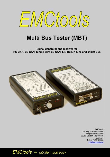
Multi Bus Tester (<strong>MBT</strong>)<br />
Signal generator and receiver for<br />
HS-CAN, LS-CAN, Single Wire LS-CAN, LIN-Bus, K-Line and J1850-Bus<br />
<strong>EMCtools</strong><br />
Dipl.-Ing. (FH) Armin Lenk<br />
Meginhardstrasse 50<br />
88356 Ostrach-Magenbuch<br />
Germany<br />
Tel: 0176/38139026<br />
info@emctools.de<br />
<strong>EMCtools</strong> – lab life made easy
<strong>MBT</strong><br />
<strong>EMCtools</strong> Multi Bus Tester (<strong>MBT</strong>)<br />
The <strong>EMCtools</strong> Multi Bus Tester simulates an automotive Device under Test (DUT) including cable harness and Load-Box<br />
inside and a separate stimulator outside the EMC chamber. Based on an analysis of commonly used bus systems in<br />
automotive tests, the <strong>EMCtools</strong> <strong>MBT</strong> provides the possibility to test six different field bus systems:<br />
1. High Speed CAN 4. LIN-bus<br />
2. Low Speed CAN 5. K-Line (L-Line)<br />
3. Low Speed Single Wire CAN 6. J1850 (class B)<br />
The <strong>MBT</strong>-set consists of a Master and a Slave unit, a load simulator with cable harness and includes cables for wiring. The<br />
Slave unit (DUT) controls 4 bulbs in a load simulator connected to the Slave unit via a cable harness of approx. 190cm length<br />
acc. ISO11451-2 immunity and CISPR25 emission standards. The Slave unit requires a supply voltage of 9 – 15 Volts from a<br />
symmetrical LISN (Line Stabilization Network or Artificial network) or 2 LISN (remote ground acc. ISO 11452-2).<br />
The Slave unit is controlled by a second device outside the EMC chamber, the Master unit. This Master unit sends bus<br />
messages to switch on and off the lights on Slave unit inside the EMC chamber. The Slave unit (DUT) loops back the<br />
received bus messages to the Master unit via fiber optic bus and the slave unit then activates LEDs on the Master unit rear<br />
panel to show the proper function of the Slave unit (DUT) and the fiber optic transmission and communication.<br />
The <strong>MBT</strong> Master unit provides a trigger signal for “bus fail” and “error frames”.<br />
The <strong>EMCtools</strong> Multi Bus Tester <strong>MBT</strong> in combination with <strong>EMCtools</strong> Microboxes has been tested for:<br />
BCI tests (ISO 11452-4):<br />
Calibration method 0.1 – 400 MHz 300mA CW/AM 1kHz 80%<br />
RI tests (ISO 11452-2)<br />
Calibration method<br />
200 – 3300 MHz 270 V/m CW/AM 1kHz 80%/Pulse Mod.<br />
Photo of a complete setup inside the EMC-chamber:<br />
Delivered devices of the system and accessories:<br />
1 pcs <strong>EMCtools</strong> <strong>MBT</strong> Slave unit (used inside EMC chamber)<br />
1 pcs <strong>EMCtools</strong> <strong>MBT</strong> Master unit (used outside EMC chamber)<br />
1 pcs red banana plug cable approx. 20cm<br />
1 pcs black banana plug cable approx. 20cm<br />
1 pcs Load simulator cable harness with Load Simulator<br />
1 pcs Cable harness<br />
1 pcs Manual <strong>EMCtools</strong> <strong>MBT</strong><br />
Technical data <strong>EMCtools</strong> <strong>MBT</strong>:<br />
Bus settings: HS-CAN: 500 kBit/s standard CAN frames (11bit identifier)<br />
LS-CAN: 100 kBit/s standard CAN frames (11bit identifier)<br />
SW LS-CAN: 33 kbit/s standard CAN frames (11bit identifier)<br />
K-Line: 10.4 Kbit/s K-Line physical layer<br />
J1850: 10.4 Kbit/s J1850 pysical layer<br />
LIN: 19.2 kBit/s LIN 2.0 data<br />
Power-Supply: 9 – 15V DC, max. 250mA, DC<br />
BUS-connector: 9-pin Sub-D<br />
Temperature range: operating/storage: -40 – 85 o C (-40 – 185 o F)<br />
Size:<br />
housing (l x w x h) 140x66x27mm, total length incl. switches 160mm<br />
Weight:<br />
Master/Slave: approx 150g<br />
© 2012 – <strong>EMCtools</strong>. All rights reserved. Subject to change (V1)