INSTALLATION INSTRUCTIONS - Bernardi Parts
INSTALLATION INSTRUCTIONS - Bernardi Parts
INSTALLATION INSTRUCTIONS - Bernardi Parts

Create successful ePaper yourself
Turn your PDF publications into a flip-book with our unique Google optimized e-Paper software.
<strong>INSTALLATION</strong><br />
<strong>INSTRUCTIONS</strong><br />
Accessory<br />
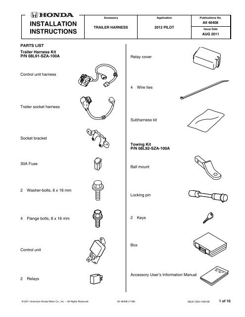
TRAILER HARNESS<br />
Application<br />
2012 PILOT<br />
Publications No.<br />
AII 46408<br />
Issue Date<br />
AUG 2011<br />
PARTS LIST<br />
Trailer Harness Kit<br />
P/N 08L91-SZA-100A<br />
Relay cover<br />
Control unit harness<br />
4 Wire ties<br />
Trailer socket harness<br />
Subharness kit<br />
Socket bracket<br />
Towing Kit<br />
P/N 08L92-SZA-100A<br />
30A Fuse<br />
Ball mount<br />
2 Washer-bolts, 6 x 16 mm<br />
Locking pin<br />
4 Flange bolts, 6 x 16 mm<br />
2 Keys<br />
Control unit<br />
Box<br />
2 Relays<br />
Accessory User’s Information Manual<br />
© 2011 American Honda Motor Co., Inc. – All Rights Reserved. AII 46408 (1108) 08L91-SZA-1A00-90 1 of 10
TOOLS AND SUPPLIES REQUIRED<br />
Phillips screwdriver<br />
Ratchet<br />
10 mm and 14 mm Sockets<br />
10 mm Open end wrench<br />
Utility knife<br />
Diagonal cutters<br />
File<br />
Locktite<br />
Torque wrench<br />
The following tool is available through the Honda Tool and<br />
Equipment Program. On the iN, click on: Service ><br />
Service Bay > Tool and Equipment Program, then enter<br />
the number under “Search”. Or, call 888-424-6857.<br />
• Plastic trim tool (T/N SILTRIMTL10)<br />
Illustration of the Trailer Harness Installed on the<br />
Vehicle<br />
20A FUSE,<br />
30A FUSE<br />
<strong>INSTALLATION</strong><br />
Customer Information: The information in this<br />
installation instruction is intended for use only by skilled<br />
technicians who have the proper tools, equipment, and<br />
training to correctly and safely add equipment to your<br />
vehicle. These procedures should not be attempted by<br />
“do-it-yourselfers.”<br />
NOTE:<br />
1. Make sure you have the anti-theft code for the audio<br />
unit and the navigation system (if equipped), then<br />
write down the radio station presets.<br />
2. Disconnect the negative cable from the battery.<br />
3. Remove the left third row seat:<br />
• Open the rear hatch, and remove the rear cargo<br />
tray (ten clips).<br />
10 CLIPS<br />
CONTROL UNIT<br />
HARNESS<br />
CONTROL<br />
UNIT<br />
REAR CARGO<br />
TRAY<br />
700101BB<br />
TRAILER<br />
SOCKET<br />
HARNESS<br />
BALL<br />
MOUNT<br />
QA33006AE<br />
2 of 10 AII 46408 (1108) © 2011 American Honda Motor Co., Inc. – All Rights Reserved.
• While inside the vehicle, use a small flat-tip<br />
screwdriver, to push on the buckle to release the<br />
seat belt lower hook from the left third row seat.<br />
• Tilt the left third row seat cushion assembly up,<br />
route for two seat belt buckles through the<br />
opening in the left third row seat.<br />
LEFT THIRD<br />
ROW SEAT<br />
BUCKLE<br />
SEAT BELT<br />
LOWER HOOK<br />
Push.<br />
QA62001AE<br />
2 SEAT<br />
BELT<br />
BUCKLES 4 BOLTS<br />
41-53 N·m<br />
(30-39 lbf·ft)<br />
700106BB<br />
• Remove the two front seat bolt covers from the<br />
left third low seat (two retaining tabs for each<br />
cover).<br />
RETAINING<br />
CLIP<br />
SEAT BELT<br />
COVER<br />
• With the left third row seat cushion assembly still<br />
tilted up, remove the remaining four seat bolts.<br />
Remove the left third row seat.<br />
NOTE: When reinstalling the third row seat,<br />
apply Honda locktite to seat bolt threads and<br />
torque the seat bolts to 41-53 N·m.<br />
4. Inside the left rear passenger’s door, remove the left<br />
rear side step (four clips).<br />
LEFT SECOND<br />
ROW SEAT<br />
CLIP<br />
2 RETAINING<br />
TABS<br />
LEFT THIRD<br />
ROW SEAT<br />
CUSHION<br />
SEAT BOLT<br />
COVER<br />
2 RETAINING<br />
TABS<br />
2 SEAT BOLTS<br />
41-53 N·m<br />
(30-39 lbf·ft)<br />
700105BB<br />
• Remove the two front seat bolts from the third<br />
seat cushion, then raise the third seat cushion<br />
assembly.<br />
3 CLIPS<br />
FRONT<br />
LEFT REAR<br />
SIDE STEP<br />
7D1902AB<br />
© 2011 American Honda Motor Co., Inc. – All Rights Reserved. AII 46408 (1108) 3 of 10
5. Using the plastic trim tool, open the two tie-down<br />
hook covers. Remove two tie-down hooks from the<br />
left rear side trim panel (one screw for each cover).<br />
COVER<br />
Open.<br />
6 CLIPS<br />
Installing the Control Unit<br />
7. Locate the threaded holes in the left rear body panel,<br />
and install the control unit using two 6 x 16 mm<br />
flange bolts.<br />
LEFT REAR SIDE<br />
TRIM PANEL OPENING<br />
LEFT REAR<br />
BODY PANEL<br />
WEATHERSTRIP<br />
BOLT<br />
HOOK<br />
Open.<br />
7 RETAINING<br />
TABS<br />
2 SCREWS<br />
FRONT<br />
LEFT REAR SIDE<br />
TRIM PANEL<br />
CLIP<br />
PLASTIC TRIM<br />
TOOL<br />
2 TIE-DOWN<br />
HOOKS<br />
DOOR<br />
OPENING<br />
SEAL<br />
2 COVERS<br />
021501AE<br />
6. Pull away the weatherstrip and door opening seal at<br />
the front and rear of the left rear side trim panel.<br />
Remove the left rear side trim panel (six clips).<br />
FLANGE<br />
BOLT,<br />
6 x 16 mm<br />
CONTROL<br />
UNIT<br />
Routing the Control Unit Harness<br />
FRONT<br />
QA32805BE<br />
8. Get the control unit harness, and plug the two relays<br />
into the relay block on the control unit harness.<br />
RELAY COVER<br />
CONTROL UNIT<br />
HARNESS<br />
RELAY BLOCK<br />
RELAY<br />
QA32806AE<br />
9. Install the relay cover to the relay block on the control<br />
unit harness.<br />
4 of 10 AII 46408 (1108) © 2011 American Honda Motor Co., Inc. – All Rights Reserved.
10. Locate the vehicle bracket, and install the clip from<br />
the relay block to the vehicle bracket.<br />
11. Locate the 14-pin connector taped to the vehicle<br />
harness. Remove the tape, and plug the control unit<br />
harness 14-pin connector into the vehicle 14-pin<br />
connector.<br />
VEHICLE<br />
BRACKET<br />
VEHICLE 14-PIN<br />
CONNECTOR<br />
VEHICLE 14-PIN<br />
CONNECTOR<br />
RELAY BLOCK<br />
FRONT<br />
CONTROL<br />
UNIT<br />
HARNESS<br />
14-PIN<br />
CONNECTOR<br />
TAPE<br />
Remove.<br />
FRONT<br />
14-PIN<br />
CONNECTORS<br />
WIRE<br />
TIE<br />
LEFT REAR SIDE<br />
TRIM PANEL OPENING<br />
CONTROL UNIT<br />
HARNESS QA51701AB<br />
CONTROL UNIT<br />
HARNESS<br />
VEHICLE<br />
HARNESS<br />
QA32902BE<br />
12. Secure the 14-pin connectors to the vehicle harness<br />
with one wire tie.<br />
13. Secure the control unit harness to the vehicle<br />
harness with one wire tie.<br />
© 2011 American Honda Motor Co., Inc. – All Rights Reserved. AII 46408 (1108) 5 of 10
14. Route the control unit harness 12-pin connector as<br />
shown, and plug it into the control unit.<br />
16. Secure the control unit harness to the vehicle<br />
harness with two wire ties.<br />
CONTROL UNIT<br />
CONTROL<br />
UNIT<br />
HARNESS<br />
CONTROL<br />
UNIT<br />
HARNESS<br />
CONTROL UNIT<br />
HARNESS 12-PIN<br />
CONNECTOR<br />
VEHICLE<br />
HARNESS<br />
FRONT<br />
QA51702AB<br />
VEHICLE<br />
HARNESS<br />
WIRE TIE<br />
FRONT<br />
QA32904BE<br />
15. Secure the clip on the control unit harness to the hole<br />
in the vehicle panel.<br />
Routing the Trailer Socket Harness<br />
17. Remove the trailer hitch cover from the rear bumper<br />
(turn and release two clips, and two retaining tabs).<br />
HOLE<br />
FRONT<br />
Turn.<br />
TRAILER<br />
HITCH<br />
COVER<br />
CLIP<br />
VEHICLE<br />
PANEL<br />
CONTROL UNIT<br />
HARNESS<br />
QA51703AB<br />
RETAINING<br />
TAB<br />
CLIP<br />
REAR<br />
BUMPER<br />
QA33001AE<br />
6 of 10 AII 46408 (1108) © 2011 American Honda Motor Co., Inc. – All Rights Reserved.
18. Using a utility knife, cut out the rear bumper in the<br />
area shown. Remove any burrs.<br />
20. Secure the trailer socket harness assembly to the<br />
vehicle frame using two 6 x 16 mm washer-bolts.<br />
TRAILER HITCH<br />
COVER OPENING<br />
Cut out.<br />
REAR<br />
BUMPER<br />
QA33002AE<br />
VEHICLE<br />
FRAME<br />
WASHER-<br />
BOLT,<br />
6 x 16 mm<br />
19. Install the socket bracket to the trailer socket<br />
harness using two 6 x 16 mm flange bolts.<br />
SOCKET<br />
BRACKET<br />
FLANGE<br />
BOLT,<br />
6 x 16 mm<br />
REAR<br />
BUMPER<br />
FRONT<br />
VIEW FROM UNDER THE VEHICLE<br />
TRAILER<br />
SOCKET<br />
HARNESS<br />
ASSEMBLY<br />
700408BE<br />
TRAILER SOCKET<br />
HARNESS<br />
700407BE<br />
© 2011 American Honda Motor Co., Inc. – All Rights Reserved. AII 46408 (1108) 7 of 10
21. Release the vehicle 10-pin connector from the<br />
connector clip, and remove the dummy connector<br />
from the vehicle 10-pin connector.<br />
24. Install the trailer socket harness clip to the vehicle<br />
frame.<br />
CONNECTOR CLIP<br />
VEHICLE<br />
FRAME<br />
VEHICLE 10-PIN<br />
CONNECTOR<br />
TRAILER<br />
SOCKET<br />
HARNESS<br />
CLIP<br />
VEHICLE 10-PIN<br />
CONNECTOR<br />
DUMMY<br />
CONNECTOR<br />
VIEW FROM UNDER THE VEHICLE<br />
700501CE<br />
22. Plug the trailer socket harness 10-pin connector into<br />
the vehicle 10-pin connector.<br />
Installing the Fuse<br />
25. In the engine compartment, remove the cover from<br />
the sub fuse box (three retaining tabs).<br />
ENGINE<br />
COMPARTMENT<br />
VIEW FROM UNDER THE VEHICLE<br />
COVER<br />
3 RETAINING<br />
TABS<br />
700503BE<br />
CONNECTOR<br />
CLIP<br />
TRAILER SOCKET<br />
HARNESS 10-PIN<br />
CONNECTOR<br />
VEHICLE 10-PIN<br />
CONNECTOR<br />
VIEW FROM UNDER THE VEHICLE<br />
700502BE<br />
23. Attach the 10-pin connectors to the connector clip as<br />
shown.<br />
FRONT<br />
SUB FUSE<br />
BOX<br />
QA33003AE<br />
8 of 10 AII 46408 (1108) © 2011 American Honda Motor Co., Inc. – All Rights Reserved.
26. Plug the 30A fuse into the sub fuse box at the<br />
location shown.<br />
30A<br />
FUSE<br />
SUB FUSE<br />
BOX<br />
Installing the Towing Kit<br />
32. Insert the ball mount into the trailer hitch, and secure<br />
it with the locking pin.<br />
TRAILER HITCH<br />
TOP VIEW<br />
LOCKING<br />
PIN<br />
FRONT<br />
SUB FUSE<br />
BOX<br />
QA62002AE<br />
BALL<br />
MOUNT<br />
QA33004AE<br />
27. Check that all wire harnesses are routed properly<br />
and that all connectors are plugged in.<br />
28. Reconnect the negative cable to the battery.<br />
29. Enter the customer’s anti-theft code for the audio<br />
and navigation system if equipped, and reset the<br />
radio station presets.<br />
30. Reset the clock.<br />
31. Reinstall all removed parts.<br />
© 2011 American Honda Motor Co., Inc. – All Rights Reserved. AII 46408 (1108) 9 of 10
Put a Copy of This Page in the Glove Box for Your Customer<br />
Using the Subharness<br />
This subharness is designed for use with the installation of an electric brake controller. Refer to the vehicle’s owner’s<br />
manual for detailed information about using this subharness.<br />
SUBHARNESS<br />
701009AB<br />
10 of 10 AII 46408 (1108) © 2011 American Honda Motor Co., Inc. – All Rights Reserved.