operating manual - Cantoni Group
operating manual - Cantoni Group
operating manual - Cantoni Group

You also want an ePaper? Increase the reach of your titles
YUMPU automatically turns print PDFs into web optimized ePapers that Google loves.
Rok załoŜenia 1878 ISO 9001<br />
OPERATING MANUAL –<br />
THREE-PHASE SQUIRREL-<br />
CAGE INDUCTION MOTORS<br />
TABLE OF CONTENTS<br />
1. SPECIFICATION AND USE. .................................................................................................................................2<br />
2. TRANSPORTATION AND STORAGE ..................................................................................................................7<br />
3. MOTOR INSTALLATION.......................................................................................................................................7<br />
3.1 Inspecting the motor prior to the assembly......................................................................................................7<br />
3.2 Checking of the insulation resistance. .............................................................................................................7<br />
3.3 Placing the geared pulley or half coupling on the motor's shaft extension. .....................................................8<br />
3.4 Motor orientation ..............................................................................................................................................9<br />
3.5 Connecting the motor to the mains..................................................................................................................9<br />
3.5.1 Direct (DOL) starting. ............................................................................................................................10<br />
3.5.2 Indirect (0-Y-∆) starting. ........................................................................................................................10<br />
3.5.3 Direction of the motor's rotation. ...........................................................................................................10<br />
3.5.4 Winding thermal protection – included upon request............................................................................10<br />
3.5.5 Anti-condensation heaters. ...................................................................................................................12<br />
4. OPERATION AND USE OF THE ELECTRIC MOTOR.......................................................................................12<br />
4.1 Operational safety regulations. ......................................................................................................................12<br />
4.2 Motor start and use........................................................................................................................................12<br />
4.3 Mating the motor to a frequency converter. ...................................................................................................13<br />
4.4 Defects in the work of a motor and their removal. .........................................................................................14<br />
5. MOTOR MAINTENANCE. ...................................................................................................................................19<br />
5.1 Periodic inspections. ......................................................................................................................................19<br />
5.2 Sizes and types of bearings...........................................................................................................................19<br />
5.3 Greased the bearings. ...................................................................................................................................20<br />
5.4 Disassembly and assembly of the motor. ......................................................................................................20<br />
6. LIST OF REPLACEMENT PARTS. .....................................................................................................................24<br />
7. ATTACHMENTS..................................................................................................................................................25<br />
PUBLICATION DATE: 25.02.2010<br />
FABRYKA MASZYN ELEKTRYCZNYCH S.A.<br />
43-300 Bielsko-Biała, ul. M. GraŜyńskiego 22, tel.: (48 33) 827 20 00, fax: (48 33) 827 20 98<br />
e-mail: indukta@cantonigroup.com www.indukta.com.pl
1. SPECIFICATION AND USE.<br />
This <strong>operating</strong> <strong>manual</strong> has been created for three-phase squirrel-cage single and dual speed induction motors, with<br />
shaft height above the mounting feet's surface of: 80, 90, 100, 112, 132, 160, 180 and 200 mm, designed to drive<br />
various types of machines and appliances. The <strong>manual</strong> also describes special motors designed to be mated to a<br />
frequency converter with an external cooling unit and brakes.<br />
Motors are adapted for indoor and outdoor use.<br />
This <strong>manual</strong> is not valid for explosion-proof motors marked with the „Ex” symbol.<br />
Design characteristics<br />
Characteristic Standard Special order version<br />
Type of operation S1 S2, S3, S4, S6<br />
Insulation class F H<br />
Protection rating IP 55 IP 65<br />
Temperature range -20 ÷ +40° -40 ÷ +120°<br />
Installation height<br />
up to 1000 m above sea<br />
level<br />
up to 4000 m above sea level<br />
Relative humidity 95% X<br />
Frame material<br />
80 aluminium X<br />
Motor size<br />
90, 100, 112 aluminium cast iron<br />
132, 160, 180, 200 cast iron X<br />
Bearing bracket material<br />
90, 100 aluminium cast iron<br />
Motor size 80,112,132, 160, 180,<br />
200<br />
cast iron<br />
X<br />
Thermal protection X PTC resistor or thermocontact<br />
Cooling system internal: IC 411 external: IC 416<br />
Terminal board 6 9 or 12<br />
Greased bearings X Motor size 132-180<br />
Motor size 90<br />
X<br />
Motor size 100<br />
Version with a brake<br />
Gripped bearing<br />
All sizes and versions<br />
Version with a brake<br />
Motor size 112-180<br />
1011, 2011, 3011, 3611,<br />
BRAKE<br />
direct current<br />
X<br />
alternating current<br />
X<br />
All sizes and versions<br />
Drain bolt Motor size 132-180 All sizes and versions<br />
Featuring a casing with a roof X All sizes and versions<br />
Number of cable inlets 1 2 and more<br />
Terminal box location top right or left side<br />
Rotating box X up to 90°<br />
Climatic version X TA, TH, MT<br />
Certificates CE declaration UL, CSA<br />
X – not available<br />
Motor markings:<br />
1 2 3 4 5 6 7 8 - 9 10 - 11 12<br />
F – motor with an external ventilation<br />
S – induction motor / on mounting feet /<br />
K – flange-type<br />
L – flange-type, on mounting feet<br />
series name, for example „g”, „h”, „EE”<br />
shaft height, for example, 100<br />
Frame size marking, for example S, M, L<br />
Number of winding poles, for example 4<br />
Marking of the pack length in the frame, for example „A”, „B”<br />
Brake marking: HS – direct current; G – alternating current<br />
(Y) – <strong>manual</strong> brake release marking<br />
OPERATING MANUAL – THREE- PHASE SQUIRREL- CAGE INDUCTION MOTORS 2/32<br />
PUBLICATION DATE: 25.02.2010 - EDITION 3
An example of a standard motor marking: SKg 100L - 4A<br />
S – three-phase squirrel-cage induction motor,<br />
K – flange-type,<br />
g- „g” series,<br />
100 – shaft height of 100 mm,<br />
L – frame size marking,<br />
4 – winding with 4 poles (for 50 Hz; 1500 rev/min),<br />
A – pack length marking.<br />
Electric motors are produced according to the current directives and norms:<br />
Requirements<br />
International marking<br />
1. Low Voltage directive 2006/95/EC (LVD)<br />
2. Machinery Directive * 2006/42/EC (MD)<br />
3. Electromagnetic compatibility 2004/108/EC (EMC)<br />
4. Electric requirements EN 60034-1<br />
IEC 60072-1<br />
EN 60034-2-1<br />
EN 60034-9<br />
EN 60034-12<br />
Norms<br />
Polish marking<br />
PN-EN 60034-1<br />
PN-IEC 72-1<br />
PN-EN 60034-2-1<br />
PN-EN 60034-9<br />
PN-EN 60034-12<br />
5. Mechanical requirements IEC 60072-1, EN 50347<br />
EN 60034-5<br />
EN 60034-6<br />
EN 60034-7<br />
EN 60034-14<br />
PN-IEC 72-1, PN-EN 50347<br />
PN-EN 60034-5<br />
PN-EN 60034-6<br />
PN-EN 60034-7<br />
PN-EN 60034-14<br />
6. Environmental requirements RoHS - UE Directive no. 2002/95/EC „Restriction on Hazardous<br />
Substances"<br />
7. Quality Management System ISO 9001 PN-ISO 9001<br />
(certificate no. 27992)<br />
* - by design the machines considered as components. Conformity to the requirements, provided that the<br />
installation is set up correctly by the tool's manufacturer.<br />
Explanation of the rating plate symbols.<br />
Name of<br />
manufacture<br />
Motor<br />
numer<br />
Motor type<br />
Rated<br />
voltage<br />
Rated<br />
power<br />
Power<br />
coefficient<br />
Type of operation S1<br />
Insulation class / surrounding temp. if other than 40°C<br />
Version<br />
Protection rating<br />
Rated<br />
frequency<br />
Rated<br />
current<br />
Rated<br />
efficiency<br />
Catalogue numer<br />
Rated<br />
rotational<br />
speed<br />
Manufacture date<br />
Month/year<br />
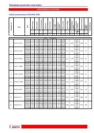
Motor <strong>operating</strong> parameters and assembly dimensions are included in the specification sheet.<br />
OPERATING MANUAL – THREE- PHASE SQUIRREL- CAGE INDUCTION MOTORS 3/32<br />
PUBLICATION DATE: 25.02.2010 - EDITION 3
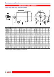
Rotating electrical machines manufactured according to PN –EN-60034-7.<br />
Horizontal shaft<br />
Vertical shaft<br />
Marking<br />
Marking<br />
System II System I System II System I<br />
IM 1001 IM B3 IM 1011 IM V5<br />
IM 1051 IM B6 IM 1031 IM V6<br />
IM 1061 IM B7 IM 2011 IM V15<br />
IM 1071 IM B8 IM 2031 IM V36<br />
IM 2001 IM B35 IM 3011 IM V1<br />
IM 2101 IM B34 IM 3031 IM V3<br />
IM 3001 IM B5 IM 3611 IM V18<br />
IM 3601 IM B14 IM 3631 IM V19<br />
OPERATING MANUAL – THREE- PHASE SQUIRREL- CAGE INDUCTION MOTORS 4/32<br />
PUBLICATION DATE: 25.02.2010 - EDITION 3
Force acting on the shaft extension should not exceed<br />
the permissible values included in the following chart.<br />
Motor type Horizontal operation* Vertical operation<br />
Number of poles<br />
Fa2<br />
Fp<br />
Fa2<br />
Fp<br />
Fa1<br />
Fa1<br />
F p F a1 = F a2 F p F a1 F a2<br />
Sg 80 2 0.44 0.13 0.44 0.10 0.13<br />
4 0.51 0.17 0.51 0.12 0.17<br />
2 0.68 0.44 0.68 0.35 0.38<br />
Sh 90 4 0.78 0.44 0.78 0.35 0.38<br />
6 0.96 0.44 0.96 0.35 0.38<br />
8 1.05 0.44 1.10 0.35 0.38<br />
2 0.88 0.46 0.90 0.28 0.40<br />
Sg 100 4 1.06 0.46 0.98 0.38 0.40<br />
6 1.20 0.46 1.10 0.38 0.40<br />
8 1.43 0.46 1.30 0.38 0.40<br />
2 1.00 0.48 1.00 0.40 0.45<br />
Sg 112 4 1.45 0.48 1.40 0.40 0.45<br />
6 1.62 0.48 1.60 0.40 0.45<br />
8 1.85 0.48 1.90 0.40 0.45<br />
2 1.82 0.66 1.90 0.43 0.60<br />
Sg 132 4 2.10 0.66 2.20 0.45 0.60<br />
6 2.80 0.66 2.80 0.50 0.60<br />
8 2.90 0.66 2.95 0.50 0.60<br />
2 2.22 0.98 2.30 0.92 0.95<br />
Sg 160 4 2.40 0.98 2.40 0.92 0.95<br />
6 2.85 1.10 2.90 0.98 1.00<br />
8 3.20 1.10 3.20 0.98 1.00<br />
2 2.92 1.30 3.00 1.10 1.20<br />
Sg 180 4 3.60 1.30 3.60 1.10 1.30<br />
6 4.00 1.80 4.10 1.40 1.70<br />
8 4.45 1.80 4.50 1.50 1.80<br />
* - forces listed in the chart and applied to the middle of the shaft neck's length.<br />
OPERATING MANUAL – THREE- PHASE SQUIRREL- CAGE INDUCTION MOTORS 5/32<br />
PUBLICATION DATE: 25.02.2010 - EDITION 3
OPERATING MANUAL – THREE- PHASE SQUIRREL- CAGE INDUCTION MOTORS 6/32<br />
PUBLICATION DATE: 25.02.2010 - EDITION 3
2. TRANSPORTATION AND STORAGE<br />
ATTENTION!<br />
When lifting drive units always use lifting handles designed for this purpose.<br />
Motors should be transported packaged, in roofed vehicles, avoiding sudden shocks and impact, secured against<br />
mechanical damage and humidity. Packaging should adequately protect the motor from mechanical damage during<br />
transport.<br />
When lifting the motor or moving it without the packaging, use the lifting eye bolt located at the top of the frame in<br />
the middle part of the motor. Do not attach the rope to motor elements which stick out, such as the terminal box,<br />
mounting feet, shaft neck, etc.<br />
Motor should be stored in a storage space, where:<br />
dust, fumes and acrid vapours and other aggressive chemical fumes which can damage the isolation or the<br />
cover cannot enter;<br />
maximum relative humidity does not exceed 80 at 20°C;<br />
in case of motors with heating or anti condensation elements, they can be plugged into mains,<br />
temperature of the surroundings is between -10°C a nd +40°C,<br />
no vibrations occur.<br />
It is important to protect processed surfaces of motors in storage from atmospheric impact, by covering them with<br />
thick grease or easily removable anti-corrosion paint.<br />
ATTENTION!<br />
After storing a motor for a period of three years, its bearings should be replaced<br />
for new ones, or the greasing should be replaced.<br />
3. MOTOR INSTALLATION.<br />
ATTENTION!<br />
Prior to starting any work on the motor, make sure that it is unplugged from<br />
mains.<br />
3.1 Inspecting the motor prior to the assembly.<br />
Before starting the motor, check:<br />
whether the motor complies with your order,<br />
whether the motor's rated voltage confirms with the network voltage,<br />
whether the motor hasn't been damaged during transportation or storage;<br />
whether the motor's rotor rotates freely (turn it <strong>manual</strong>ly),<br />
whether the surrounding temperature in the location of the motor's installation does not exceed + 40°C, (for<br />
maritime motors,+45°C or +50°C, according to the ma ritime association regulations),<br />
whether free flow of cooling air, necessary for proper operation of the motor, will be provided,<br />
Minimal distance between the end the motor's frame and other elements:<br />
for shaft height 90 mm – 15 mm<br />
for shaft height 100 and 112 mm – 20 mm<br />
for shaft height 132, 160 and 180 mm – 40 mm<br />
<br />
tightness of all mounting screws on the motor.<br />
3.2 Checking of the insulation resistance.<br />
Inspection of the insulation's condition should be done prior to starting the motor, if moistness of the winding is<br />
suspected, or after a lengthy standstill or storage period (about 6 months).<br />
Insulation resistance should be measured using 500V direct current.<br />
ATTENTION!<br />
During, and directly after measuring the insulation resistance, harmful voltage is<br />
present in the terminals, therefore it is forbidden to touch them. In order to remove<br />
the threat of electrocution, it is necessary to discharge the winding.<br />
The minimal value of the insulation resistance in regard to the frame or between phases in the temperature<br />
of 25°C ± 15°C for a new or repaired motor is 10 M Ω.<br />
OPERATING MANUAL – THREE- PHASE SQUIRREL- CAGE INDUCTION MOTORS 7/32<br />
PUBLICATION DATE: 25.02.2010 - EDITION 3
While the motor is in operation, the insulation resistance may drop, however, it cannot be below the critical<br />
insulation resistance value, which is a product of inter-wire supply voltage and constant coefficient<br />
0.5MΩ/kV. In case of a motor powered by a frequency converter, the minimal value of the motor's insulation<br />
resistance is 1 MΩ. During the measurement, the winding should be in <strong>operating</strong> temperature.<br />
An example of a motor powered from a 3 x 400V network: 0,4kV x 0,5MΩ/kV= 0,2 MΩ.<br />
If the expected winding resistance falls below the level of the critical resistance value, the motor should be<br />
immediately taken out of service and the cause of the lowered resistance value - moistness, pollution, damage, etc -<br />
removed. After the repair or drying, the conditions of insulation should be checked again. .<br />
During the drying process, create conditions necessary to remove moisture from the winding, i.e. at least, take off<br />
the cover of the terminal box in order to make the exchange of air with the interior of the motor possible. For motor<br />
sizes 132, 160 and 180, there is a possibility to drain the condensate by unscrewing the drain plugs installed in the<br />
bearing brackets. The recommended drying temperature is 60 to 80°C. The motor should be dried until in sulation<br />
resistance reaches its minimal value (2-8h).<br />
In case of motors with heating elements, drying can be performed by connecting them to the mains. Another<br />
method of drying is single-phase powering of two out of the three motor outlets with a voltage with a value of about<br />
0.2 of the rated voltage. This way, the motor will not spin, and the value of the input current will be from 25% to 35%<br />
of rated current. Heating the motor's winding using the heating elements or single-phase powering prevents the<br />
condensation of steam and can be done during the whole period of standstill.<br />
3.3 Placing the geared pulley or half coupling on the motor's shaft extension.<br />
Prior to placing the geared pulley or the half coupling on the motor's shaft extension:<br />
remove any possible injury marks from the shaft extension,<br />
remove protective paint from the shaft extension,<br />
lightly cover the shaft extension with grease,<br />
clean anti-corrosion layer from the flange disc,<br />
Placing the geared /wedged/ pulley or the half coupling should be done with the use of an appropriate tool, as<br />
shown in fig. 1 – using the threaded centre hole of the shaft extension.<br />
Fig. 1<br />
If necessary, heat up the coupling hub or the pulley /belt, geared/ to about 80°C.<br />
In no special equipment is available, the heated up coupling or geared pulley can be hammered on using a suitable<br />
sleeve, simultaneously supporting the opposite shaft extension, so the force from the hits is transferred to the<br />
support, not the bearings.<br />
After putting the belt, wedged, geared pulley or half coupling on the shaft extension, secure it from sliding off the<br />
shaft using a screw with a washer, screwed in the threaded centre hole of the shaft extension.<br />
OPERATING MANUAL – THREE- PHASE SQUIRREL- CAGE INDUCTION MOTORS 8/32<br />
PUBLICATION DATE: 25.02.2010 - EDITION 3
3.4 Motor orientation<br />
Motor should be oriented in such a way so that it is structurally adapted as much as possible to have easy access<br />
for inspection and operations relating with its maintenance.<br />
Motor on mounting legs can be mounted directly on anchor bolts or on take-ups allowing for belt tension<br />
adjustment.<br />
When connecting the motor to the driven appliance using a coupling, particular attention needs to be given to the<br />
concentricity of shafts: the motor and of the driven machine's shafts – as shown in fig. 2.<br />
For belt drives, it is recommended to use transmissions with wedge belts, which have:<br />
smaller slide,<br />
quieter operation,<br />
lower belt tension.<br />
Lower belt tension results in a lower risk of damaging motor's bearing from the drive side.<br />
Correct assembly and appropriately balanced coupling element have a significant effect on the drive's<br />
vibrations and quite operation.<br />
Correct<br />
setting<br />
Maximum permissible non-concentricity<br />
a = 0.25 mm<br />
b = b 2 - b 1 = 0.1mm/∅ 200mm<br />
Fig.2 Motor orientation<br />
3.5 Connecting the motor to the mains.<br />
ATTENTION!<br />
The earthing or the protective conductor should be connected to the terminal marked<br />
with the earthing symbol located in the terminal box or on the motor's frame.<br />
Earthing conductor profiles are specified in attachment no. 3.<br />
Each motor has a rating plate attached to its frame. This rating plate includes information such as:<br />
supply voltage – permissible deviation ±5% not requiring decreasing the power;<br />
supply voltage frequency – permissible deviation ±2% not requiring decreasing the power;<br />
connection of the 3-phase winding in a star (Y) or a delta (∆);<br />
input current at rated load.<br />
The box contains a terminal board with 3 or 6 terminals. Power cables should be led in to the terminal box through<br />
stuffing boxes or glands. The screwed in cable inlets should prevent water and dust from entering the terminal box<br />
during operation. Stuffing box throttle range is included in attachment no. 1.<br />
Power leads should have a cable tips. Torque values, with which the nuts and screws of the electric connections<br />
should be tightened, are listed in attachment no. 2.<br />
Detailed rules regarding installing electric motors are given in PN-E-05012.<br />
OPERATING MANUAL – THREE- PHASE SQUIRREL- CAGE INDUCTION MOTORS 9/32<br />
PUBLICATION DATE: 25.02.2010 - EDITION 3
3.5.1 Direct (DOL) starting.<br />
Each motor is adapted for direct starting.<br />
In case of a 3-terminal board, motor is designed for one voltage, which is indicated on the rating plate. Direct start<br />
can take place by plugging directly into the mains, after making sure that the inter-wire voltage of the mains is equal<br />
to the rated voltage of the connected motor.<br />
In case of a 6-terminal board, using the connectors supplied with the motor, create a correct phase match, meaning<br />
Y or ∆, and connect the power supply to the terminals in accordance to the connection diagram attached with the<br />
motor – attachment no. 4.<br />
An example: motor marked 230/400Y V can be connected in two ways, depending on the supply network:<br />
in a ∆ connection if inter-wire voltage is 3 x 230V or<br />
in a Y connection if inter-wire voltage is 3 x 400V.<br />
3.5.2 Indirect (0-Y-∆) starting.<br />
0-Y-∆ start can take place only in motors with 6–cioma outlets from one winding, and supply voltage must be equal<br />
to the motor's rated voltage in a ∆ connection. Connectors should be removed from the terminal board.<br />
Indirect starting is used in order to limit the motor's starting current and large drops of voltage in the mains as an<br />
effect of high starting voltage. Remember that the motor with a nominal connection in ∆ has a 3 times smaller<br />
starting torque in an Y connection, that's why the 0-Y-∆ start should be performed without load or with the lowest<br />
possible load. Start of the motor begins with the Y connection, and after achieving a stable rotational speed by the<br />
motor, switches to ∆. If the motor cannot start in the Y connection, instead of using the 0-Y-∆ start, use the direct<br />
start method. If start is still impossible, reanalyze the starting conditions and motor selection.<br />
An example: starting a motor marked 400∆/690YV or 400∆V powered by a 3 x 400V network:<br />
connection in Y – operation 10s,<br />
switch to ∆ - constant operation,<br />
put the motor under load.<br />
Detailed regulations regarding installing electric motors are given in PN-E-05012.<br />
3.5.3 Direction of the motor's rotation.<br />
The standard direction of rotation is clockwise, as seen from the shaft extension's drive side, when the power supply<br />
phases L1, L2, L3 are connected according to the diagram attached with the motor – attachment no. 4. In order to<br />
change the rotation direction, change any two power supply phases.<br />
3.5.4 Winding thermal protection – included upon request.<br />
Two types of thermal protection are used in motors:<br />
thermal bimetal,<br />
PTC-resistor.<br />
Terminals of PTC-resistor temperature sensors should be connected with the appropriate input terminals on the<br />
resistance relay, and terminals of thermal bimetal NC temperature sensors can be connected directly to the motor's<br />
safety circuit (fig 4).<br />
Motors, in which the stator's winding has buried thermal protection, have finishing leads of the beginnings and ends<br />
of temperature sensors, which are connected in series, connected to an additional terminal block, in the terminal<br />
boxes.<br />
Thermocontact sensors.<br />
Three thermocontacts are located in the motor's winding, connected in series (fig. 3). Each one is placed in a<br />
different phase.<br />
Fig. 3<br />
T 1 T 1<br />
OPERATING MANUAL – THREE- PHASE SQUIRREL- CAGE INDUCTION MOTORS 10/32<br />
PUBLICATION DATE: 25.02.2010 - EDITION 3
An example of the power supply system of a motor with thermal protection using thermocontacts is presented in<br />
drawing 4a.<br />
Fig. 4<br />
Technical parameters of thermocontact S01.150.05:<br />
contact opening temperature - 150ºC°C ±5ºC°C<br />
rated current - 250V, 50 ÷ 60Hz<br />
load:<br />
2,5A at cosφ=1<br />
1,6A at cosφ=0,6<br />
max load – 40.A at cosφ=1<br />
contact system – normally closed<br />
electric resistance of the insulation – 2.0kV<br />
resistance - 4000 Ω<br />
rated current - ≤2,5V-<br />
max current – 30V-<br />
electric resistance of the insulation – 2.5kV<br />
OPERATING MANUAL – THREE- PHASE SQUIRREL- CAGE INDUCTION MOTORS 11/32<br />
PUBLICATION DATE: 25.02.2010 - EDITION 3
3.5.5 Anti-condensation heaters.<br />
Anti-condensation heaters are used in cases of a risk of steam condensation inside the motor. The effect of steam<br />
condensation can take place during long-term standstill of a cold motor in humid air. In such a case, turn on the<br />
heaters for a few hours prior to starting the motor, and after drying check the insulation resistance value as<br />
described in chapter 3.2 or keep the heaters turned on during the whole standstill period.<br />
For motor sizes 132, 160 and 180, there is a possibility to drain the condensate by unscrewing the drain plugs<br />
installed in the bearing brackets.<br />
Do not power the heaters while the motor is in operation.<br />
Standard heaters: 2 heaters, 25W each, running on 230V current with three leads.<br />
When connected parallel, the power supply current may amount to 200-240V, and connecting in series allows for<br />
powering the heaters with 400-480V current.<br />
4. OPERATION AND USE OF THE ELECTRIC MOTOR.<br />
4.1 Operational safety regulations.<br />
In order to avoid unfortunate accidents while <strong>operating</strong> the motors, it is important to follow these rules:<br />
electric motor operators should be familiar with the operational safety regulations regarding electric devices and<br />
their operation, the motor cannot in any case be in operation without a functional earthing.<br />
The quality of earthing or neutralization should be checked periodically for the reason that contacts may loosen<br />
or get corroded. Do not perform any repairs while the motor is in operation;<br />
maintenance, inspections or repairs of the motor can be performed only on a motor disconnected from the<br />
mains;<br />
the motor should be earthed or neutralized in accordance with current regulations in this regard. The quality of<br />
earthing (neutralization) should be inspected periodically;<br />
the motor cannot be operated without the cover of the external fan and without the cover of the coupling or the<br />
belt, fan or gear transmission, with elements leading current exposed,<br />
each location where the electric motion takes place should be equipped with a fire extinguisher filled with nonconducting<br />
extinguishing agent.<br />
safety devices preventing accidents from occurring should be present in the location of the installation, in<br />
accordance with local safety regulations.<br />
4.2 Motor start and use.<br />
Prior to starting the previously prepared motor, as described in chapter 3, check the functionality of control circuit on<br />
an unloaded motor. Check whether the change of rotational speed takes place and whether the motor is spinning in<br />
the correct direction.<br />
Motor can be started by:<br />
connecting to the mains directly,<br />
an indirect 0-Y-∆ start.<br />
Both methods are described in details in chapter 3.5.<br />
The maximum number of consecutive starts is dependent on the degree of starting difficulty and limited by the<br />
maximum temperature increase for the given heat resistance class of insulation.<br />
While the motor is in operation, systematically check the correctness of such operations as:<br />
the state of motor heating up on its frame – in some types of motors, the temperature increase of the frame can<br />
reach as much as 70K;<br />
correct functioning of bearings – which is manifested by quiet, even humming,<br />
whether there are no excessive vibrations of the motor,<br />
the condition of the motor's coupling with the powered machine,<br />
current input shouldn't exceed the nominal value.<br />
Normal, stable work can take place with current fluctuation not exceeding ±5% of the rated current and ±2% of the<br />
rated frequency.<br />
The motor should be turned off immediately in case of:<br />
smoke or fire, etc. coming out of the motor or the installation;<br />
excessive heating of the motor;<br />
significant decrease of rotational speed,<br />
damaging of the external fan;<br />
damaging of the driven machine;<br />
when, for any reason, further work of the motor and the driven machine is a threat to the surroundings.<br />
Switching on the motor and the appliance again can take place after all defects have been removed.<br />
OPERATING MANUAL – THREE- PHASE SQUIRREL- CAGE INDUCTION MOTORS 12/32<br />
PUBLICATION DATE: 25.02.2010 - EDITION 3
4.3 Mating the motor to a frequency converter.<br />
Standard motors powered with AC up to 400V, series Sg and Sh, manufactured by FME Indukta, have an insulation<br />
system making it possible to be powered through frequency converters. For heat factors, it is not recommended to<br />
power progressive Psg or PSh series motors through converters.<br />
These converters allow for adjusting the motor's rotational speed. Do not exceed the maximum rotational speeds of<br />
the motor listed in the following chart:<br />
Motor size<br />
2p=2 2p=4 2p=6 2p=8<br />
rev/min<br />
90 ÷112 5200 3600 2400 2000<br />
132 ÷ 200 4500 2700 2400 2000<br />
Attention: If adjusting the frequency (rotational speed) above 200% of the rated frequency, it is<br />
recommended to use motors with external cooling and better balance of rotor.<br />
Adjustment of rotational speed, depending on the load torque, can take place only in scope presented in the<br />
following graph, and the maximum load torque of induction motors with external cooling, depending on the<br />
frequency of supplied current, is presented in graph no. 2.<br />
120<br />
M aximum load torque of induction motors<br />
w ith internal cooling, manufactured by FM E Indukta,<br />
depending on the frequency of supplied current,<br />
for continuous duty S1.<br />
100<br />
M/M n<br />
[%]<br />
80<br />
60<br />
40<br />
20<br />
0<br />
0 10 20 30 40 50 60 70 80 90 100 110 120 130 140 150 160 170 180 190 200<br />
f /f n [% ]<br />
Graph no. 1<br />
120<br />
M axim um load torque of induction m otors<br />
w ith external cooling, manufactured by FM E Indukta,<br />
depending on the frequency of supplied current,<br />
for continuous duty S1.<br />
100<br />
M/M n [%]<br />
80<br />
60<br />
40<br />
20<br />
0<br />
0 10 20 30 40 50 60 70 80 90 100 110 120 130 140 150 160 170 180 190 200<br />
f /f n [%]<br />
Graph no. 2<br />
OPERATING MANUAL – THREE- PHASE SQUIRREL- CAGE INDUCTION MOTORS 13/32<br />
PUBLICATION DATE: 25.02.2010 - EDITION 3
9550 ⋅ P [kW]<br />
M [Nm] =<br />
−1<br />
Analysing the formula: n [min ] notice that the increase of rotational speed, while maintaining a<br />
constant torque, must be accompanied by an increase of power. With speeds exceeding the rated speed, the<br />
increase of power would cause an increase of the current drawn by the motor, which causes motor overheating. For<br />
this reason, in rotational speed higher than the rated speed, the load torque on the shaft needs to be lowered. While<br />
<strong>operating</strong> the motor in rotational speed higher than the rated speed, pay attention to the current drawn by the motor,<br />
and make sure that it is not higher than the rated current.<br />
While the motor is operated in speeds higher that the rated speed, the level of noise and vibrations increases, and<br />
the life span of bearings can be shorter. Attention: do not exceed the rotational speed listed in chart.<br />
A method of eliminating these unfavourable effects can be:<br />
using dU/dt filters, which smooth out the rate of output voltage,<br />
blocking the frequencies in the inverter, in which the unfavourable effects take place,<br />
change of the carrier frequency (transistor keying),<br />
adjusting other inverter parameters.<br />
The ratio of the output voltage to the frequency converter's output frequency, in the range up to the rated frequency,<br />
is constant, which is a condition of achieving constant torque on the motor's shaft. Above the rated frequency, the<br />
voltage value is constant, which results from the voltage value of the converter's power supply. A motor, whose the<br />
rated voltage when connected in a star is equal to the rated voltage of the frequency converter, can be connected in<br />
a delta. Its rated voltage will now be<br />
This will make it possible to extend the range<br />
of operation with a rated torque to 86.6 Hz. The new value of the motor's rated voltage should be entered into the<br />
frequency converter.<br />
Attention: When making the connections described above, it is recommended to consult with the supplier of<br />
the converter in regard to the new frequency converter settings.<br />
An example: Having a 230∆/400Y motor, connected in a star and a frequency converter with output voltage<br />
(ratio U/f=8), we can connect the motor in a delta (Un=230V) and set this parameter in the<br />
converter (U/f=4.6). This way the adjustment range on the motor's shaft, with a constant torque, increases to<br />
86.6Hz.<br />
For example:<br />
Rated voltage of<br />
motor<br />
Rated<br />
frequency<br />
Rated current Rated output<br />
Maximal<br />
output<br />
400V Y (U/f=8) 50Hz 6,2A 3,0kW 3,0kW<br />
230V ∆ (U/f=4,6) 50Hz 10,7A 3,0kW 5,2kW (87Hz)<br />
Withstand voltage stress of insulation.<br />
Motors up to 400V AC have insulating system compatible with standard IEC TS 60034-17, resistant for<br />
voltage impulses 1.35kV at the impulse rise time ≥0,8µs. When using converters without any reduction of voltage<br />
impulses such motors are suitable for drive systems only up to 400V AC supply voltage within a restricted range of<br />
cable length. When using filtering devices, such motors can be used for drive systems up to 690V supply voltage<br />
and without limits of cable length.<br />
Recommended is using filters on inverter output, which eliminate considerably problems with overvoltage,<br />
acoustic effects, reduce current ripples. Filters protect motor isolation and elongate time of using the motors.<br />
4.4 Defects in the work of a motor and their removal.<br />
Defects, which can be the reason of most frequent motor malfunctions, are listed in the following chart.<br />
DEFECT CAUSE SOLUTION<br />
Motor overloaded<br />
Decrease the load.<br />
Incorrect power supply.<br />
Motor not moving or moves heavily<br />
when idling<br />
Incorrect connection system.<br />
Rotor damage.<br />
Check the voltage of the power<br />
cable terminals, check the power<br />
lead connection, check the setting<br />
on the frequency converter –<br />
remove the cause.<br />
Check the connections against the<br />
diagram supplied with the motor<br />
Look for cracked bars or end rings<br />
OPERATING MANUAL – THREE- PHASE SQUIRREL- CAGE INDUCTION MOTORS 14/32<br />
PUBLICATION DATE: 25.02.2010 - EDITION 3
Motor stalls<br />
A short circuit in the motor's winding<br />
or incorrect winding connection.<br />
Blown fuses.<br />
Automatic switch-off caused by<br />
overloading.<br />
Broken power supply or control<br />
circuit.<br />
Mechanical damage.<br />
One of the phases may be open.<br />
Bad motor selection.<br />
Overload.<br />
Low voltage.<br />
Open power supply or control circuit.<br />
Remove the short circuit, remove<br />
the bad connection or rewind the<br />
motor.<br />
Replace the blown fuses with a<br />
correct type of fuses with<br />
appropriate rated values.<br />
Check the starter settings.<br />
When the switch is closed, buzzing<br />
can be heard. Check for looseness<br />
in lead connections. Also check<br />
whether all control contacts and<br />
closed.<br />
Check whether the motor and the<br />
drive rotate freely. Check the<br />
bearings and greasing.<br />
Check if there is a broken phase on<br />
the lines<br />
Change the type or size. Contact the<br />
device's supplier or designer.<br />
Decrease the load<br />
Check whether the voltage stated on<br />
the rating plate is maintained. Check<br />
the connection.<br />
Blown fuses, check the load relay,<br />
stator and control buttons.<br />
Adjust the gap.<br />
Motor braking doesn't take place<br />
despite switching off the power<br />
The brake's air gap has exceeded<br />
its maximum value.<br />
(regards motors with a brake) Power supply voltage too low Increase the power supply voltage.<br />
U
Incorrect power supply connection.<br />
Too many starts per hour.<br />
Too many starts per hour.<br />
Ventilation openings in the<br />
ventilator's or console's cover may<br />
be blocked with dirt, preventing<br />
correct motor ventilation.<br />
Connect the motor according to the<br />
diagram.<br />
Increase the intervals in the motor<br />
operation, eventually decrease the<br />
number of switchings<br />
Increase the intervals in the motor<br />
operation, eventually decrease the<br />
number of switchings<br />
Clean the ventilation openings and<br />
check for the continuity of the air<br />
flow from the motor.<br />
The gap between the core and the<br />
shifted brake armature is higher<br />
than 0.06mm in places.<br />
Axial run-out of the brake lock's<br />
front in relation to the shaft's axis is<br />
higher than 0.05mm.<br />
Brake power supply voltage too low<br />
(HZg, HYg) U
Overloaded thermal release turns<br />
the motor off during operation.<br />
Motor vibrates.<br />
A short circuit in the stator's winding<br />
or a short circuit to the frame (to the<br />
ground).<br />
A break in the motor's connection or<br />
winding.<br />
Incorrect connection system.<br />
Single-phase power supply.<br />
Motor overloaded<br />
Incorrect power supply.<br />
Rotor damage.<br />
A short circuit in the motor's winding<br />
or incorrect winding connection.<br />
A break in the motor's connection or<br />
winding.<br />
Incorrect connection system.<br />
Incorrect overload range setting in<br />
the thermal release<br />
Single-phase power supply.<br />
Motor baldy aligned.<br />
Weak mounting.<br />
Unbalanced coupling.<br />
Driven appliance unbalanced.<br />
Bearings damaged.<br />
Unaligned bearings.<br />
Displaced balance weights.<br />
Unbalanced motor and coupling unit<br />
Multiphase motor operates in a<br />
single phase.<br />
Excessive axial looseness<br />
on the frequency converter –<br />
remove the cause<br />
Find and remove the short circuit<br />
(rewind the motor).<br />
Find and remove the break.<br />
Connect the motor correctly.<br />
Check the voltage of the power<br />
cable terminals, check the power<br />
lead connection.<br />
Decrease the load<br />
Check the voltage of the power<br />
cable terminals, check the power<br />
lead connection, check the setting<br />
on the frequency converter –<br />
remove the cause.<br />
Look for cracked bars or end rings<br />
Remove the short circuit, remove<br />
the bad connection or rewind the<br />
motor.<br />
Find and remove the break.<br />
Connect the motor correctly.<br />
Set the overload protection correctly.<br />
Check the voltage of the power<br />
cable terminals, check the power<br />
lead connection, check the setting<br />
on the frequency converter –<br />
remove the cause<br />
Re-align.<br />
Enforce the base.<br />
Balance the coupling.<br />
Balance the driven appliance.<br />
Replace the bearing.<br />
Re-align correctly.<br />
Balance the motor.<br />
Balance the unit.<br />
Check whether the motor has an<br />
open circuit.<br />
Adjust the bearing or add a washer<br />
Grinding<br />
Noisy operation.<br />
Brake buzzing while switching the<br />
motor off<br />
The ventilator rubs against the<br />
cover.<br />
The fan is hitting the cover.<br />
Looseness on the base plate.<br />
Uneven air gap.<br />
Spinning parts not balanced.<br />
Belt tension too high.<br />
Incorrect coupling of the motor with<br />
the driven machine.<br />
A break in the brake's<br />
electromagnet circuit.<br />
Break in the lead supplying power to<br />
the brake.<br />
Brake's air gap has exceeded its<br />
Eliminate the friction.<br />
Clean the fan and the cover, check<br />
the fan's mounting on the shaft.<br />
Tighten the clamping screws.<br />
Check and correct the bracket or<br />
bearing mounting.<br />
Find and remove the mechanical<br />
damage (rotor, pulley, coupling,<br />
ventilator, and carefully balance).<br />
Adjust the motor orientation and belt<br />
tension<br />
Replace the bearings. Adjust the<br />
motor orientation and belt tension<br />
Replace the electromagnet.<br />
Remove the damage.<br />
Adjust the gap.<br />
OPERATING MANUAL – THREE- PHASE SQUIRREL- CAGE INDUCTION MOTORS 17/32<br />
PUBLICATION DATE: 25.02.2010 - EDITION 3
Bearings heat up.<br />
Motor seizes up.<br />
maximum value.<br />
Power supply voltage too low<br />
U
5. MOTOR MAINTENANCE.<br />
In order to maintain the motor in full technical efficiency, it is necessary to remove all defects noticed during<br />
operation on an ongoing basis.<br />
Regardless of the above, every working motor should be subjected to periodic maintenance inspections. Time<br />
periods between maintenances, running and major repairs, are dependent on the conditions of motor's work.<br />
ATTENTION!<br />
In order to attempt any type of work related with the motor or its elements,<br />
especially prior to taking off protective covers, prior to directly touching moving<br />
parts or parts which can be under current, unplug the motor and all additional and<br />
support circuits from the mains.<br />
5.1 Periodic inspections.<br />
Customary time periods are as follows:<br />
• running inspection every 6 months (for dust-laden room, every 3 months)<br />
• main inspection – once every 30 months.<br />
Running inspections – performed at the<br />
location of motor's installation, without a<br />
disassembly. This type of inspection can reveal a<br />
need to subject the motor to a main inspection.<br />
Main inspections – include the following<br />
operations:<br />
Running inspections include the following<br />
operations:<br />
cleaning the motor and a visual<br />
inspection,<br />
measuring the insulation resistance of<br />
the winding;<br />
examining the condition of power cables<br />
and the earthing cable;<br />
checking the tightness of all mounting<br />
and contact screws;<br />
<br />
<br />
<br />
<br />
disassembly of the motor,<br />
stator inspection,<br />
inspection of the rotor,<br />
inspection of bearings and bearing<br />
chambers;<br />
<br />
removal of condensate in motors<br />
featuring drain plugs in the disks<br />
<br />
measurement of insulation resistance of<br />
the winding;<br />
<br />
inspection of the starting and protective<br />
devices.<br />
AFTER A MAIN INSPECTION AND ANY EVENTUAL REPAIRS OF THE MOTOR'S WINDING, CHECK THE<br />
CONDITION OF THE WINDING'S INSULATION AS DESCRIBED IN CHAPTER 3.2.<br />
Additionally, in motors with brakes, inspect the brake elements. A detailed description of the brakes is included in<br />
attachment no. 5. In case of a large number of switchings, inspect the brakes more often than every 6 months.<br />
All defects noticed during the inspection should be removed, and worn out parts replaced with new ones.<br />
It is recommended to renew the protective layers.<br />
5.2 Sizes and types of bearings.<br />
Size and type of bearings used in different types of motors:<br />
S(K, L)h 90 - 6205-2Z-C3<br />
S(K, L)g 100 - 6206-2Z-C3<br />
S(K, L)g 112 - 6306-2Z-C3<br />
S(K, L)g 132 - 6308-2Z-C3<br />
S(K, L)g 160 - 6309-2Z-C3<br />
S(K, L)g 180 - 6311-2Z-C3<br />
S(K, L)g 200 on the drive side - 6311-2Z-C3 ; S(K, L)g 200 on the non-drive side - 6213-2Z-C3<br />
OPERATING MANUAL – THREE- PHASE SQUIRREL- CAGE INDUCTION MOTORS 19/32<br />
PUBLICATION DATE: 25.02.2010 - EDITION 3
5.3 Greased the bearings.<br />
Bearings closed on both sides /type 2Z/ are filled with grease by the manufacturer which lasts for their whole life<br />
span. The life span of standard bearings is 25 000 hours.<br />
After the expiration of the motor's warranty it is recommended to replace the bearings for new ones.<br />
Bearings in motors with buried grease nipples in bearing brackets (fig. 6) should be greased periodically. Greasing<br />
periods, type and amount of grease are listed in the following chart:<br />
Gland size<br />
Amount of<br />
refilled grease [g]<br />
Grease refilling period [h]<br />
n≥1500 rpm<br />
3000 rpm<br />
80 3 2500 1500<br />
90 4 2500 1500<br />
100 5 2500 1500<br />
112 7 2500 1500<br />
132 10 1500 1000<br />
160 12 1500 1000<br />
180 17 1500 1000<br />
200 17 1500 1000<br />
Grease type<br />
as specified by<br />
the motor's<br />
documentation<br />
5.4 Disassembly and assembly of the motor.<br />
Fig. 6<br />
By principle, motor disassembly should take place outside the place of its operation, in a specially<br />
prepared location.<br />
Tools required include a regular set of assembly tools and instruments. Prior to a correct disassembly, take off the<br />
motor pulley or the half coupling using a turnbuckle (fig. 8), remove the key (7) from the shaft extension, unscrew 4<br />
screws (5) and remove the ventilator cover (13) (fig. 7). After unscrewing 4 screws (5) which mount the bearing<br />
brackets "P", carefully remove the rotor (1) with the bearing brackets "P" (11) and the ventilator (8) from the stator,<br />
without damaging the winding. If it is necessary, or when replacing the grease, remove both bearings (17) using a<br />
turnbuckle.<br />
Prior to removing the "P" bearing (), it is necessary to:<br />
<br />
remove the spring clip mounting the ventilator (10) and take off the ventilator (8) from the rotor's shaft along<br />
with the key, using a turnbuckle;<br />
remove the "P" bearing bracket (11) from the rotor's shaft (1).<br />
After completing these steps, remove the "P" bearing (17) using a turnbuckle.<br />
OPERATING MANUAL – THREE- PHASE SQUIRREL- CAGE INDUCTION MOTORS 20/32<br />
PUBLICATION DATE: 25.02.2010 - EDITION 3
Fig. 7<br />
Fig. 8<br />
Attention: For motors with a gripped bearing fig. 9 and 10, (also regards vertical motors), prior to the disassembly of<br />
the bearing it is necessary to:<br />
• remove 3 screws mounting the bearing cover (4) and remove the rotor's spring clip (3) (this also regards<br />
motors with a closed bearing chamber - see fig. 9)<br />
• remove the spring clip in the bearing brackets (3) and rotor (4) (this also regards motors with a open<br />
bearing chamber – see fig. 10).<br />
OPERATING MANUAL – THREE- PHASE SQUIRREL- CAGE INDUCTION MOTORS 21/32<br />
PUBLICATION DATE: 25.02.2010 - EDITION 3
Fig. 9 Fig. 10<br />
In case of a motor with a brake (fig. 11), prior to the disassembly of the motor it is necessary to disassemble the<br />
brake (19).<br />
In case of motors with an external ventilation system (fig. 12), external ventilation (10) is disassembled along with<br />
the cover.<br />
Fig. 11<br />
OPERATING MANUAL – THREE- PHASE SQUIRREL- CAGE INDUCTION MOTORS 22/32<br />
PUBLICATION DATE: 25.02.2010 - EDITION 3
Fig. 12<br />
Fig. 13 Fig. 14<br />
OPERATING MANUAL – THREE- PHASE SQUIRREL- CAGE INDUCTION MOTORS 23/32<br />
PUBLICATION DATE: 25.02.2010 - EDITION 3
Disassembly of the motor's terminal box is done in accordance with drawing no. 13. Depending on the type of<br />
motor, following terminal box settings are available:<br />
• custom version (fig. 14)<br />
• version with an HPS brake (fig. 15)<br />
• version with an HZG brake (fig. 16)<br />
Fig. 15 Fig. 16<br />
Motor assembly should be done in reverse order.<br />
After a correct assembly, the rotor should freely turn when spinning the shaft neck <strong>manual</strong>ly.<br />
6. LIST OF REPLACEMENT PARTS.<br />
• Rotor set<br />
• Bearing bracket N - machining<br />
• Flange bracket - machining<br />
• Gasket ring (V-ring)<br />
• Spring washer<br />
• Bearing N<br />
• Bearing cover - machining<br />
• Cover's felt ring<br />
• Bearing bracket P - machining<br />
• Bearing P<br />
• Rotor's stopper ring<br />
• Ventilator<br />
• Ventilator cover<br />
• Terminal box set<br />
OPERATING MANUAL – THREE- PHASE SQUIRREL- CAGE INDUCTION MOTORS 24/32<br />
PUBLICATION DATE: 25.02.2010 - EDITION 3
7. ATTACHMENTS.<br />
Attachment no. 1 Throttle range of cable glands.<br />
Gland size Throttle range in<br />
[mm]<br />
M12 3.5 ÷ 7<br />
M16 4.5 ÷ 10<br />
M20 7 ÷ 13<br />
M25 9 ÷ 17<br />
M32 11 ÷ 21<br />
M40 19 ÷ 28<br />
Attachment no. 2. Torque values for the tightness of nuts and screws.<br />
Thread M 4 M 5 M 6 M 8 M10 M12 M16<br />
Torque<br />
value in<br />
Min. 0.8 1.8 2.7 5.5 9 14 27<br />
[Nm] Max. 1.2 2.5 4 8 13 20 40<br />
Attachment no. 3 Minimal earthing or protective lead profiles.<br />
Live lead profile S [mm 2 ] Earthing or protective conductor profile<br />
[mm 2 ]<br />
S ≤ 25<br />
S<br />
25 < S ≤ 50 25<br />
S > 50<br />
0.5 S<br />
OPERATING MANUAL – THREE- PHASE SQUIRREL- CAGE INDUCTION MOTORS 25/32<br />
PUBLICATION DATE: 25.02.2010 - EDITION 3
Attachment no. 4. Standard motor terminal connection diagrams.<br />
1. 3-phase single-speed motors:<br />
Connection in a ∆<br />
Connection in a Y<br />
2. 3-phase dual-speed general use motors (single-winding), for example, 2p=4/2, 8/4:<br />
GEAR 1 2p=4(8)(12)<br />
Connection in a ∆<br />
GEAR 2 2p=2(4)(6)<br />
Connection in a YY<br />
3. 3-phase dual-speed motors (double-winding), for example 2p=6/4, 8/6:<br />
GEAR 1 2p=4(8)(12)<br />
Connection in a Y<br />
GEAR 2 2p=2(4)(6)<br />
Connection in a Y<br />
4. 3-phase dual-speed ventilator motor (single-winding), for example 2p=4/2W, 8/4W – motor marking ending in<br />
„W":<br />
GEAR 1 2p=4(8)(12)<br />
GEAR 2 2p=2(4)(6)<br />
Connection in a Y<br />
Connection in a YY<br />
5. 3-phase dual-speed motors (nine terminals), for example 2p=4/2, 8/4:<br />
Connection in a ∆ Connection in a Y Connection in a YY<br />
OPERATING MANUAL – THREE- PHASE SQUIRREL- CAGE INDUCTION MOTORS 26/32<br />
PUBLICATION DATE: 25.02.2010 - EDITION 3
ATTENTION! Do not supply power to the external cooling or the brake using the frequency converter.<br />
6. 3-phase single-speed motors:<br />
a) with an AC brake b) with an independently powered AC brake<br />
c) with a DC brake d) with an independently powered DC brake<br />
7. Diagram of supplying power to external cooling – in standard versions, motors have a separate external cooling<br />
box.<br />
OPERATING MANUAL – THREE- PHASE SQUIRREL- CAGE INDUCTION MOTORS 27/32<br />
PUBLICATION DATE: 25.02.2010 - EDITION 3
Attachment no. 5. Disk brakes type H, HPS and H(Z,Y)g.<br />
1. Construction and principle of operation<br />
a) type H brake<br />
The electromagnetic DC brake type „H” consists of<br />
3 main units: the electromagnet (1), the armature<br />
(2) and the cast iron fan (3).<br />
Switching on the electromagnet (1), supplying direct<br />
current from the motor through the rectifying circuit<br />
causes the armature (2) to be shifted, with a<br />
simultaneous release of the fan (3) and the brake is<br />
released.<br />
Switching off the electromagnet (1) causes the<br />
armature to be moved (2) through the springs until<br />
the torque is created and the brake lining is pressed<br />
against the ventilator. The brake is immobilized (halted).<br />
10<br />
9<br />
4<br />
2<br />
5<br />
1<br />
a<br />
3<br />
7<br />
6<br />
8<br />
b) HPS type brake<br />
The construction of the brake is presented in the<br />
drawing. When no current is fed to the coil (2), the<br />
brake disk (5) with friction lining is pressed by the<br />
armature (4) to the mounting disk (5) or directly to<br />
the surface of the given device with the force of the<br />
springs (8), the brake is then in the 'on' state (it is<br />
braking). The braking torque is transferred by the<br />
13 12<br />
brake disk (5) to the gear (6) located on the motor's<br />
11 9 10<br />
5<br />
8<br />
shaft, or the device mated to the brake, protected<br />
7<br />
from axial displacement with a spring clip. The<br />
6<br />
torque size can be adjusted by screwing in the nut<br />
(3) or reducing the number of springs.<br />
Direct current fed to the electromagnet's winding (2),<br />
15<br />
4<br />
3<br />
2<br />
through its excitation, causes the armature to be<br />
shifted (a=0), at the same time eliminating the<br />
pressure of the springs on the armature and the<br />
brake disk (5). The brake is released.<br />
If no voltage is present or a damaged electromagnet<br />
a<br />
1<br />
in the brake with a hand-release lever, it is possible to release the brake by moving the lever. Releasing the<br />
pressure on the lever causes its return and repeated braking. Adjustment screws (11) set the distance between the<br />
electromagnet and the mounting disk (5) or the motor's bearing brackets, regulating the size of the air gap. HPS<br />
type brakes are mounted to the motor's bearing brackets using clamping screws (10).<br />
The air gap „a” is factory set to the rated value; as the brake disk gets worn, the depth of the clamping screws' drive<br />
(11) is increased by the size of performed adjustments.<br />
H(Z,Y)g type brake<br />
The brake disk (7) has two friction linings (8) located<br />
HZg<br />
HZYg<br />
between the mounting disk (9) and the armature (2).<br />
In brakes designed to be mounted directly to the<br />
motor's bearing bracket, or to the mated device, it<br />
serves the role of the second friction surface for the<br />
brake disk. Force caused by the pressure of the<br />
springs (4) acts on the armature, which is<br />
transferred to the brake disk (7) causing it to rub<br />
against the armature and the mounting disk, causing<br />
9 3 12 4<br />
S<br />
11 6 13 10 15 14<br />
a braking torque this way. The size of the torque can<br />
be changed by reducing the number of springs.<br />
Alternating current fed to the electromagnet's<br />
winding (5) causes the S = 0 armature to be shifted,<br />
eliminating the pressure of the springs on the<br />
8 1 7 2 5<br />
S1<br />
armature, releasing the brake. In case of brakes with a lever (14) is it possible to <strong>manual</strong>ly release the brake by<br />
moving the lever; releasing the pressure causes it to automatically return to the starting position and repeated<br />
braking.<br />
OPERATING MANUAL – THREE- PHASE SQUIRREL- CAGE INDUCTION MOTORS 28/32<br />
PUBLICATION DATE: 25.02.2010 - EDITION 3
Adjustment screws (3) screwed into the bearing ring (6) set the distance of the electromagnet to the face surface of<br />
the mounting disk (motor's bearing bracket), setting the air gap S value.<br />
Brakes are clamped using 3 screws (13) spaced every 120 degrees, and 3 screws (10) connect the brake's<br />
elements with the mounting disk. In case of a brake without the mounting disk, its assembly is done using 6 screws<br />
spaced every 60 degrees.<br />
A rubber band (12), sealing the brake is placed on the brake's cover (11), which has openings allowing for adjusting<br />
the air gap. In new brakes, the air gap is set to the value S nom. As the brake disk's friction lining gets worn with<br />
use, its value cannot exceed the value of S max. Exceeding the maximum value with reduce the braking effect by<br />
lowering the braking torque which can cause damage to the electromagnet, which may fail to shift the armature and<br />
release the brake due to the exceeded maximum value of the air gap. Therefore it is necessary to adjust it by<br />
setting the s nom value.<br />
S nom.. Maximum friction lining wear is 3 mm per side, which allows for multiple adjustments of the air gap. As the<br />
wear of the lining increases, the depth of clamping screws drive also increases (10) and (13), and with worn out<br />
lining it can reach 6 mm.<br />
2. Assembly and disassembly of the brake<br />
a) type H brake<br />
A condition of correct functioning of the brake is to maintain perpendicularity of the surface on which the brake<br />
rests, in relation to the motor's axis.<br />
Mounting the brake on the motor with an adapted bearing bracket and motor's shaft takes place using three<br />
clamping screws (4), spaced 3x120°. Next, the shaft is put on the central spring (5), which is rested on the bearing's<br />
inner ring. Tightly screw in the clamping screw (7) to the motor's shaft and put on the fan (3), which is led on the<br />
internal diameter and a key channel.<br />
Put the special washer (6) on the fan (3) and the clamping screw (7), and tighten the nut self-locking (8) until a 0.2<br />
air gap is set (see chart 1).<br />
Put on the gasket ring (9) between the frame (electromagnet (1)) and armature, than cover the brake with the<br />
motor's cover.<br />
Chart 1<br />
TYPE H-63 H-71 H-80 H-90 H-100 H-112 H-132 H-160<br />
rated gap „a” 0.2 ±0,05 0.2 ±0,05 0.2 ±0,05 0.2 ±0,05 0.2 ±0,1 0.2 ±0,1 0.2 ±0,1 0.2 ±0,1<br />
b) HPS type brake<br />
Brakes are very simple to assemble. Mount the gear (6) on the shaft and secure from axial displacement with a<br />
spring clip. After putting the brake disk (5) on the gear, mount the brake using clamping screws (10) to the motor's<br />
bearing cover, mounting plate (7) or wall of the mated device. If the brake has blocking elements (14), they should<br />
be removed after mounting the brake. Check the air gap „a” value, which should be equal to the „a nom” value listed<br />
in chart 2. In case of finding a discrepancy, adjust the gap as described in paragraph 3. Put on the brake cover.<br />
Disassembly should be done in reverse order.<br />
Chart 2<br />
TYPE HPS06 HPS08 HPS10 HPS12 HPS14 HPS16 HPS18 HPS20 HPS25<br />
a nom. 0.2 ±0,05 0.2 ±0,05 0.2 ±0,05 0.3 ±0,05 0.3 ±0,05 0.3 ±0,05 0.3 ±0,05 0.3 ±0,05 0.3 ±0,05<br />
a max. 0,5 0,5 0,5 0,7 0,8 1,0 1,0 1,2 1,4<br />
c) H(Z,Y)g type brake<br />
H(Z,Y)g brakes are very simple to assemble. Mount the gear (1) on the shaft and secure from axial displacement<br />
with a spring clip. After putting the brake disk (7) on the gear, mount the brake using clamping screws to the motor's<br />
bearing bracket or wall of the mated device. Use cast iron or steel as the friction surface. If case of difficulties<br />
creating a friction surface on the mated device, use a mounting plate (9).<br />
Check the correctness of assembly, the air gap value, which guarantees a correct work of the brake; connect the<br />
brake to the mains, or a mated electric motor.<br />
OPERATING MANUAL – THREE- PHASE SQUIRREL- CAGE INDUCTION MOTORS 29/32<br />
PUBLICATION DATE: 25.02.2010 - EDITION 3
Disassembly of the brake should be done in reverse order.<br />
3. Electric connection system<br />
a) H type brake and HPS type brake<br />
When the DC brake needs to be connected to an AC source, two rectifying circuits are used. The attachable coil of<br />
the brake's electromagnet circuit can be detached on the direct or alternating current side.<br />
- SWITCHING OFF ON THE ALTERNATING CURRENT SIDE<br />
W<br />
~ A C = D C<br />
BRAKE<br />
When switching off the voltage, the magnetic field causes that the coil's current flows through the rectifying diode<br />
and falls slowly. Magnetic field is reduced gradually, which causes a lengthened period of the brake's operation,<br />
which means a delayed increase of the braking torque. If the working time is insignificant, the brake should be<br />
connected on the alternating current side, since no other protection for the coil and the contacts is needed. When<br />
being switched off, supply circuits act as unidirectional diodes.<br />
- SWITCHING OFF ON THE DIRECT CURRENT SIDE<br />
~AC<br />
W<br />
= DC<br />
BRAKE<br />
Coil's current is broken between the coil and the power supply (rectifying) circuit. Magnetic field is reduced very<br />
quickly, brake's operation time is short, in consequence, the braking torque increases quickly. When tripping on the<br />
side of direct current in the coil, high peak voltage is generated causing faster wearing out of contacts due to<br />
sparking. In order to protect the coil against peak voltage and to protect the contacts from excessive wear, the<br />
rectifying circuits have protection allowing to connect the brake on the direct current side.<br />
b) H(Z,Y)g type brake<br />
Connecting the brake is done according to the above drawing.<br />
L1<br />
L2<br />
L3<br />
BRAKE<br />
4. Adjustment of the air gap<br />
a) HPS type brake<br />
Air gap „a” increases as a result of the brake disk (5) wearing out. The appropriate initial „a nom.” value of the gap<br />
can be restored by screwing in the adjustment screws (11) into the frame (1). When adjusting, loosen the clamping<br />
screws (10), use a gap gauge inserted between the armature and the frame by screwing in the adjustment screws<br />
(11), set the air gap to the rated value. Tighten the clamping screws (10) – total stiffening of the attachment point is<br />
achieved by countering it with adjustment screws, meaning by unscrewing them to the limit with the mounting plate<br />
of the surface of the mated device.<br />
b) H(Z,Y)g type brake<br />
OPERATING MANUAL – THREE- PHASE SQUIRREL- CAGE INDUCTION MOTORS 30/32<br />
PUBLICATION DATE: 25.02.2010 - EDITION 3
Correct work of the brake is ensured when the S and S1 gaps have correct values.<br />
Gap values:<br />
S nom = 0.4 mm S max = 1.4 mm S 1 = 2 mm<br />
In case of exceeding the listed S max value, adjust the air gap immediately. In order to do this:<br />
- remove the rubber band (12),<br />
- loosen the screws (10) and (13) clamping the brake, unscrewing them half a turn,<br />
- through openings in the cover (11), tighten the adjustment screws (3) to the bearing ring (6) by about 2 mm<br />
2mm<br />
- place a gap gauge with thickness of S nom +/- 0.05 mm in the gap between the electromagnet's core (5) and the<br />
armature (2).<br />
- using clamping screws, press the core to the armature so that the gap gauge can be taken out with little resistance<br />
and with the same resistance insert it in gaps every 120 degrees from the place of initial measurement,<br />
- unscrew adjustment screws so they rest on the mounting plate or the motor's bearing bracket, or another mated<br />
device,<br />
- tighten the brake's clamping screws and check the size of gap S,<br />
- in brakes with a <strong>manual</strong> release lever (14), self-locking nuts (15) must be set so that their distance from the<br />
armature plate S 1=2mm is maintained when the armature is shifted, i.e. when S = 0.<br />
5. Periodic inspections<br />
Each brake being used should be inspected at least once a year.<br />
The work period, after which an inspection is required, depends on the intensity of motion and are listed in<br />
regulations for individual devices, for example for crane devices.<br />
During the inspection (after removing the rubber band and the brake cover):<br />
- remove dirt which has collected in the brake's interior,<br />
- check the size of the gap using a gap gauge:<br />
a) type H brake; adjust the air gap to the value listed in chart 1, using a self-locking nut (8).<br />
The adjustment can be performed many times, until the brake lining is worn out. When the brake lining is<br />
completely worn out, replace the armature with the brake lining (2) for new ones;<br />
b) HPS type brake; check the gap in accordance with paragraph 4 a) and chart 1; c) type H(Z,Y)g brake; S1 between<br />
the armature and castellated nuts. The sum of the measured gaps S + S 1 (in braking state) should amount to 1.8-2<br />
mm; adjust if needed;<br />
- perform few braking tests, check the effectiveness of braking.<br />
If significant decrease in the effectiveness of braking is noticed in relation to the initial state, the brake should be<br />
disassembled in order to check the condition of friction lining, tracks and springs.<br />
When the brake disk achieves its maximum wear, it should be replaced for a new one (the lining's working surface<br />
has levelled out with the aluminium bearing element of the brake disk). When replacing the brake disk, make sure<br />
that the friction surface of the disk, the armature and the elements mated with friction lining are free from grease<br />
and oil.<br />
If the brake, despite correct assembly and appropriate adjustment, does not work:<br />
- the electromagnet has been damaged – the coil burned out, power lead damaged<br />
- the rectifying circuit (installed in the motor's terminal box or machine's control cabinet) has been damaged<br />
- check the correctness and quality of electric connections<br />
- replace damaged elements for new ones.<br />
Check the electric units mentioned above and replace damaged ones.<br />
Attachment no. 6. External cooling parameters.<br />
OPERATING MANUAL – THREE- PHASE SQUIRREL- CAGE INDUCTION MOTORS 31/32<br />
PUBLICATION DATE: 25.02.2010 - EDITION 3
EXTERNAL COOLING FAN SPECIFICATION<br />
Motor size<br />
Rated<br />
voltage<br />
Frequency Rated current Input power Speed Air flow Noise level<br />
[V] [Hz] [A] [W] [min -1 ] [m 3 /min] [dB]<br />
90/100/112 1 x 230 50/60 0,23/0,21 32/31 2800/3100 5,40/6,60 50/55<br />
132/160/180 1 x 230 50/60 0,24/0,27 56/60 2100/1900 24,0/21,8 57/55<br />
Type of<br />
protection<br />
Impedance<br />
protection<br />
Thermal<br />
protection<br />
• surrounding temperature from -20 to +80[°C],<br />
• installation height up to 1000 [m] above sea level,<br />
• life span – 50 000 h in 25°C temperature,<br />
• insulation class B,<br />
• motor protection<br />
• – thermal protection – automatic motor switch-off after achieving winding temperature of 110°C, autom atic<br />
switch-on after the temperature decreases to 70°C,<br />
• – impedance protection – motor can operate in abnormal conditions, such as rotor lockup.<br />
• protection rating IP 55,<br />
• ball bearings.<br />
OPERATING MANUAL – THREE- PHASE SQUIRREL- CAGE INDUCTION MOTORS 32/32<br />
PUBLICATION DATE: 25.02.2010 - EDITION 3