⢠Table of Contents ⢠Index ⢠Safety and Notices ... - josvandijken.nl
⢠Table of Contents ⢠Index ⢠Safety and Notices ... - josvandijken.nl
⢠Table of Contents ⢠Index ⢠Safety and Notices ... - josvandijken.nl

Create successful ePaper yourself
Turn your PDF publications into a flip-book with our unique Google optimized e-Paper software.
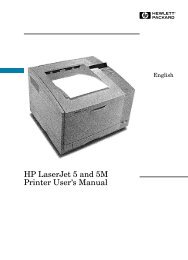
Lexmark C720<br />
Color Laser Printer<br />
Machine Type 5024-001<br />
• <strong>Table</strong> <strong>of</strong> <strong>Contents</strong><br />
• Start Diagnostics<br />
• <strong>Safety</strong> <strong>and</strong> <strong>Notices</strong><br />
• Trademarks<br />
•<strong>Index</strong><br />
• Manuals Menu<br />
Lexmark <strong>and</strong> Lexmark with diamond<br />
design are trademarks <strong>of</strong> Lexmark<br />
International, Inc., registered in the<br />
United States <strong>and</strong>/or other countries.
5024-001<br />
<strong>Table</strong> <strong>of</strong> <strong>Contents</strong><br />
<strong>Notices</strong> <strong>and</strong> <strong>Safety</strong> Information . . . . . . . . . . . . . . . . . . . . . . . . . . . xiii<br />
Laser <strong>Notices</strong> . . . . . . . . . . . . . . . . . . . . . . . . . . . . . . . . . . . . . . . . . . xiii<br />
<strong>Safety</strong> Information . . . . . . . . . . . . . . . . . . . . . . . . . . . . . . . . . . . . . xxiv<br />
Preface . . . . . . . . . . . . . . . . . . . . . . . . . . . . . . . . . . . . . . . . . . . . . . . xxx<br />
General Information . . . . . . . . . . . . . . . . . . . . . . . . . . . . . . . . . . . . 1-1<br />
Maintenance Approach . . . . . . . . . . . . . . . . . . . . . . . . . . . . . . . . . . 1-1<br />
Tools Required for Service . . . . . . . . . . . . . . . . . . . . . . . . . . . . . . . . 1-1<br />
Serial Number . . . . . . . . . . . . . . . . . . . . . . . . . . . . . . . . . . . . . . . . . 1-2<br />
Acronyms . . . . . . . . . . . . . . . . . . . . . . . . . . . . . . . . . . . . . . . . . . . . . 1-3<br />
St<strong>and</strong>ard Features . . . . . . . . . . . . . . . . . . . . . . . . . . . . . . . . . . . . . . 1-4<br />
Printer (Main) . . . . . . . . . . . . . . . . . . . . . . . . . . . . . . . . . . . . . . . . 1-4<br />
Printer Options . . . . . . . . . . . . . . . . . . . . . . . . . . . . . . . . . . . . . . 1-11<br />
Printer Identification . . . . . . . . . . . . . . . . . . . . . . . . . . . . . . . . . . . . 1-12<br />
Options Identification . . . . . . . . . . . . . . . . . . . . . . . . . . . . . . . . . . . 1-13<br />
Printer Theory <strong>of</strong> Operation . . . . . . . . . . . . . . . . . . . . . . . . . . . . . . 1-14<br />
Printer Systems Description . . . . . . . . . . . . . . . . . . . . . . . . . . . . . . 1-15<br />
Basic Principles <strong>of</strong> Color Printing . . . . . . . . . . . . . . . . . . . . . . . . 1-15<br />
Mechanical <strong>and</strong> Electrical Structures . . . . . . . . . . . . . . . . . . . . . 1-15<br />
Printer Component Systems . . . . . . . . . . . . . . . . . . . . . . . . . . . 1-17<br />
Basic Process <strong>of</strong> Color Printing . . . . . . . . . . . . . . . . . . . . . . . . . 1-18<br />
Print System <strong>and</strong> Transfer System . . . . . . . . . . . . . . . . . . . . . . 1-19<br />
Structure <strong>of</strong> OPC Belt (Photo Developer Cartridge). . . . . . . . . . 1-20<br />
Basic Structure <strong>of</strong> the Print System . . . . . . . . . . . . . . . . . . . . . . 1-21<br />
Details <strong>of</strong> the Print System . . . . . . . . . . . . . . . . . . . . . . . . . . . . . . . 1-23<br />
Charging Process. . . . . . . . . . . . . . . . . . . . . . . . . . . . . . . . . . . . 1-23<br />
Exposing Process . . . . . . . . . . . . . . . . . . . . . . . . . . . . . . . . . . . 1-25<br />
Developing Process . . . . . . . . . . . . . . . . . . . . . . . . . . . . . . . . . . 1-26<br />
First Transfer (Drum) Process . . . . . . . . . . . . . . . . . . . . . . . . . . 1-28<br />
Belt Discharge (Erase Lamp) Process . . . . . . . . . . . . . . . . . . . . 1-30<br />
Belt Cleaning Process . . . . . . . . . . . . . . . . . . . . . . . . . . . . . . . . 1-31<br />
Details <strong>of</strong> the Transfer System . . . . . . . . . . . . . . . . . . . . . . . . . . . . 1-32<br />
Second Transfer (Paper) Process . . . . . . . . . . . . . . . . . . . . . . . 1-32<br />
Paper Discharging Process . . . . . . . . . . . . . . . . . . . . . . . . . . . . 1-33<br />
Drum Cleaner Process. . . . . . . . . . . . . . . . . . . . . . . . . . . . . . . . 1-34<br />
Details <strong>of</strong> the Optical System . . . . . . . . . . . . . . . . . . . . . . . . . . . . . 1-35<br />
Details <strong>of</strong> the Paper Transportation System . . . . . . . . . . . . . . . . . . 1-37<br />
Fusing Unit . . . . . . . . . . . . . . . . . . . . . . . . . . . . . . . . . . . . . . . . . 1-39<br />
Fusing Process . . . . . . . . . . . . . . . . . . . . . . . . . . . . . . . . . . . . . 1-41<br />
iii
5024-001<br />
Control System Structure . . . . . . . . . . . . . . . . . . . . . . . . . . . . . . . .1-42<br />
Electrical System <strong>and</strong> Function . . . . . . . . . . . . . . . . . . . . . . . . . .1-42<br />
Control <strong>of</strong> Print Process . . . . . . . . . . . . . . . . . . . . . . . . . . . . . . .1-43<br />
Print Sequence Diagram . . . . . . . . . . . . . . . . . . . . . . . . . . . . . .1-44<br />
Laser Drive Control Circuit . . . . . . . . . . . . . . . . . . . . . . . . . . . . .1-45<br />
Interface Control . . . . . . . . . . . . . . . . . . . . . . . . . . . . . . . . . . . . .1-47<br />
Lower Feed Unit Theory <strong>of</strong> Operation . . . . . . . . . . . . . . . . . . . . . . .1-48<br />
Duplex Theory <strong>of</strong> Operation . . . . . . . . . . . . . . . . . . . . . . . . . . . . . .1-49<br />
Diagnostic Information . . . . . . . . . . . . . . . . . . . . . . . . . . . . . . . . . .2-1<br />
Start . . . . . . . . . . . . . . . . . . . . . . . . . . . . . . . . . . . . . . . . . . . . . . . . . .2-1<br />
Service Error Codes . . . . . . . . . . . . . . . . . . . . . . . . . . . . . . . . . . . . .2-2<br />
Operator Messages . . . . . . . . . . . . . . . . . . . . . . . . . . . . . . . . . . . . . .2-9<br />
Paper Jam Messages . . . . . . . . . . . . . . . . . . . . . . . . . . . . . . . . . . .2-27<br />
Symptom <strong>Table</strong>s . . . . . . . . . . . . . . . . . . . . . . . . . . . . . . . . . . . . . . .2-32<br />
Printer Symptom <strong>Table</strong> . . . . . . . . . . . . . . . . . . . . . . . . . . . . . . . .2-32<br />
Print Quality Symptom <strong>Table</strong> . . . . . . . . . . . . . . . . . . . . . . . . . . .2-34<br />
Optional Lower Feed Unit Symptom <strong>Table</strong> . . . . . . . . . . . . . . . .2-36<br />
Optional Duplex Unit Symptom <strong>Table</strong> . . . . . . . . . . . . . . . . . . . .2-37<br />
Printer Service Checks . . . . . . . . . . . . . . . . . . . . . . . . . . . . . . . . . .2-38<br />
901—Yellow Developer Clutch Service Check . . . . . . . . . . . . .2-38<br />
902—Magenta Developer Clutch Service Check . . . . . . . . . . . .2-39<br />
903—Cyan Developer Clutch Service Check . . . . . . . . . . . . . . .2-40<br />
904—Black Developer Clutch Service Check . . . . . . . . . . . . . .2-41<br />
905—Yellow/Black Developer Solenoid Service Check . . . . . . .2-42<br />
906—Magenta/Cyan Developer Solenoid Service Check . . . . .2-43<br />
907—Toner Empty Sensor P.W.B. Board Service Check . . . . .2-44<br />
910—Developer Motor (DM) Drive Service Check . . . . . . . . . . .2-45<br />
911—Main Motor (MM) Service Check . . . . . . . . . . . . . . . . . . .2-47<br />
915—Control Cooling Fan Service Check . . . . . . . . . . . . . . . . .2-50<br />
916—Ozone Fan Service Check . . . . . . . . . . . . . . . . . . . . . . . .2-51<br />
917—Fuser Heater Fan Service Check . . . . . . . . . . . . . . . . . . .2-52<br />
918—Erase Lamp Service Check . . . . . . . . . . . . . . . . . . . . . . .2-53<br />
920, 922, 923—Fuser Unit Service Check . . . . . . . . . . . . . . . . .2-54<br />
921—Fuser Thermistor Service Check . . . . . . . . . . . . . . . . . . .2-55<br />
981—Duplex Motor (DPM1, DPM2) Service Check . . . . . . . . . .2-56<br />
982—Duplex Upper Solenoid (DSOL-U) Service Check . . . . . .2-58<br />
983— Duplex Fan (D-FAN) Service Check . . . . . . . . . . . . . . . .2-59<br />
984—Duplex Lower Solenoid (DSOL-L) Service Check . . . . . .2-60<br />
990—Transfer Drum Encoder Sensor (HPSEN) Service Check 2-61<br />
991—Transfer Roller Cam Clutch (TRCM) Service Check . . . .2-63<br />
992—Drum Cleaner Brush Cam Clutch (FBCM)<br />
Service Check . . . . . . . . . . . . . . . . . . . . . . . . . . . . . . . . . . . . . .2-64<br />
iv Service Manual
5024-001<br />
993—Cleaner Clutch (FBCL) Service Check . . . . . . . . . . . . . . 2-65<br />
994—Fuser Clutch (FUCL) Service Check . . . . . . . . . . . . . . . . 2-66<br />
995—OPC Belt Cartridge, Belt Marker Sensor (PBS)<br />
Service Check . . . . . . . . . . . . . . . . . . . . . . . . . . . . . . . . . . . . . . 2-67<br />
997—High Voltage Power Supply Unit (HVU) Service Check . 2-69<br />
OPC Belt (Photo Developer) Cartridge Drive Service Check . . 2-70<br />
Operator Panel Service Check. . . . . . . . . . . . . . . . . . . . . . . . . . 2-70<br />
Options No Power Service Check . . . . . . . . . . . . . . . . . . . . . . . 2-72<br />
Paper Discharge Service Check . . . . . . . . . . . . . . . . . . . . . . . . 2-73<br />
Printer No Power Service Check . . . . . . . . . . . . . . . . . . . . . . . . 2-74<br />
Toner Feed Service Check . . . . . . . . . . . . . . . . . . . . . . . . . . . . 2-75<br />
Waste Toner Feed Service Check . . . . . . . . . . . . . . . . . . . . . . 2-76<br />
Paper Feed Service Checks . . . . . . . . . . . . . . . . . . . . . . . . . . . . . . 2-77<br />
Printer Paper Feed Service Check . . . . . . . . . . . . . . . . . . . . . . 2-77<br />
Lower Feed Unit Paper Feed Service Check . . . . . . . . . . . . . . 2-79<br />
Duplex Paper Feed Service Check . . . . . . . . . . . . . . . . . . . . . . 2-81<br />
Print Quality Service Checks . . . . . . . . . . . . . . . . . . . . . . . . . . . . . 2-83<br />
Background Service Check . . . . . . . . . . . . . . . . . . . . . . . . . . . . 2-83<br />
Back Stain Service Check . . . . . . . . . . . . . . . . . . . . . . . . . . . . . 2-84<br />
B<strong>and</strong>ing Service Check . . . . . . . . . . . . . . . . . . . . . . . . . . . . . . . 2-85<br />
Black Line Service Check . . . . . . . . . . . . . . . . . . . . . . . . . . . . . 2-86<br />
Color Misregistration Service Check . . . . . . . . . . . . . . . . . . . . . 2-87<br />
Insufficient Fusing Service Check . . . . . . . . . . . . . . . . . . . . . . . 2-88<br />
Insufficient Gloss Service Check . . . . . . . . . . . . . . . . . . . . . . . . 2-89<br />
Jitter Service Check . . . . . . . . . . . . . . . . . . . . . . . . . . . . . . . . . 2-90<br />
Missing Image at Edge Service Check . . . . . . . . . . . . . . . . . . . 2-91<br />
Mixed Color Image Service Check . . . . . . . . . . . . . . . . . . . . . . 2-92<br />
Mottle Service Check . . . . . . . . . . . . . . . . . . . . . . . . . . . . . . . . 2-93<br />
Residual Image Service Check . . . . . . . . . . . . . . . . . . . . . . . . . 2-94<br />
Ribbing Service Check . . . . . . . . . . . . . . . . . . . . . . . . . . . . . . . 2-95<br />
Toner Drop Service Check . . . . . . . . . . . . . . . . . . . . . . . . . . . . 2-96<br />
Vertical Line Service Check . . . . . . . . . . . . . . . . . . . . . . . . . . . 2-97<br />
Vertical Staggering Image Service Check . . . . . . . . . . . . . . . . . 2-98<br />
Vertical White B<strong>and</strong> Service Check . . . . . . . . . . . . . . . . . . . . . 2-99<br />
White B<strong>and</strong> Service Check . . . . . . . . . . . . . . . . . . . . . . . . . . . 2-100<br />
White Line I Service Check . . . . . . . . . . . . . . . . . . . . . . . . . . . 2-101<br />
White Line II Service Check . . . . . . . . . . . . . . . . . . . . . . . . . . 2-102<br />
White Spot / Black Spot Service Check . . . . . . . . . . . . . . . . . 2-103<br />
White Print Service Check . . . . . . . . . . . . . . . . . . . . . . . . . . . 2-104<br />
Wrinkle / Image Migration Service Check . . . . . . . . . . . . . . . . 2-105<br />
Spacing <strong>Table</strong> . . . . . . . . . . . . . . . . . . . . . . . . . . . . . . . . . . . . . . . 2-106<br />
Roller Specifications . . . . . . . . . . . . . . . . . . . . . . . . . . . . . . . . 2-106<br />
v
5024-001<br />
Diagnostic Aids . . . . . . . . . . . . . . . . . . . . . . . . . . . . . . . . . . . . . . . .3-1<br />
Disabling Dow<strong>nl</strong>oad Emulations . . . . . . . . . . . . . . . . . . . . . . . . . . . .3-1<br />
Paper Jam Sequence . . . . . . . . . . . . . . . . . . . . . . . . . . . . . . . . . . . .3-2<br />
Diagnostic Mode . . . . . . . . . . . . . . . . . . . . . . . . . . . . . . . . . . . . . . . .3-5<br />
Diagnostics Menu Structure . . . . . . . . . . . . . . . . . . . . . . . . . . . . .3-6<br />
Print Quality Test Pages . . . . . . . . . . . . . . . . . . . . . . . . . . . . . . . .3-6<br />
Print Registration . . . . . . . . . . . . . . . . . . . . . . . . . . . . . . . . . . . . . . . .3-7<br />
Setting Tray 2 Left Margin . . . . . . . . . . . . . . . . . . . . . . . . . . . . . . .3-7<br />
Setting Top Margin . . . . . . . . . . . . . . . . . . . . . . . . . . . . . . . . . . . .3-7<br />
Print Tests . . . . . . . . . . . . . . . . . . . . . . . . . . . . . . . . . . . . . . . . . . . . .3-8<br />
Hardware Tests . . . . . . . . . . . . . . . . . . . . . . . . . . . . . . . . . . . . . . . . .3-9<br />
LCD Test . . . . . . . . . . . . . . . . . . . . . . . . . . . . . . . . . . . . . . . . . . . .3-9<br />
Button Test . . . . . . . . . . . . . . . . . . . . . . . . . . . . . . . . . . . . . . . . . .3-9<br />
Parallel Wrap Test. . . . . . . . . . . . . . . . . . . . . . . . . . . . . . . . . . . .3-10<br />
ROM Memory Test . . . . . . . . . . . . . . . . . . . . . . . . . . . . . . . . . . .3-10<br />
DRAM Memory Test . . . . . . . . . . . . . . . . . . . . . . . . . . . . . . . . . .3-11<br />
Serial Wrap Test . . . . . . . . . . . . . . . . . . . . . . . . . . . . . . . . . . . . .3-12<br />
Duplex Tests . . . . . . . . . . . . . . . . . . . . . . . . . . . . . . . . . . . . . . . . . .3-13<br />
Duplex Left Margin . . . . . . . . . . . . . . . . . . . . . . . . . . . . . . . . . . .3-13<br />
Device Tests . . . . . . . . . . . . . . . . . . . . . . . . . . . . . . . . . . . . . . . . . .3-14<br />
Quick Disk Test . . . . . . . . . . . . . . . . . . . . . . . . . . . . . . . . . . . . . .3-14<br />
Disk Test/Clean . . . . . . . . . . . . . . . . . . . . . . . . . . . . . . . . . . . . . .3-14<br />
Flash Test . . . . . . . . . . . . . . . . . . . . . . . . . . . . . . . . . . . . . . . . . .3-15<br />
Printer Setup . . . . . . . . . . . . . . . . . . . . . . . . . . . . . . . . . . . . . . . . . .3-16<br />
Setting the Page Count . . . . . . . . . . . . . . . . . . . . . . . . . . . . . . . .3-16<br />
Viewing the Permanent Page Count . . . . . . . . . . . . . . . . . . . . . .3-16<br />
Serial Number . . . . . . . . . . . . . . . . . . . . . . . . . . . . . . . . . . . . . . .3-16<br />
Setting Configuration ID . . . . . . . . . . . . . . . . . . . . . . . . . . . . . . .3-17<br />
Parallel Strobe Adjustment . . . . . . . . . . . . . . . . . . . . . . . . . . . . .3-18<br />
Resetting Counters . . . . . . . . . . . . . . . . . . . . . . . . . . . . . . . . . . . . .3-19<br />
Error Log . . . . . . . . . . . . . . . . . . . . . . . . . . . . . . . . . . . . . . . . . . . . .3-19<br />
Viewing the Error Log . . . . . . . . . . . . . . . . . . . . . . . . . . . . . . . . .3-19<br />
Clearing the Error Log . . . . . . . . . . . . . . . . . . . . . . . . . . . . . . . . .3-20<br />
Restore EP Factory Defaults. . . . . . . . . . . . . . . . . . . . . . . . . . . .3-20<br />
Exiting Diagnostic Mode . . . . . . . . . . . . . . . . . . . . . . . . . . . . . . . . .3-21<br />
Print Quality Test Page . . . . . . . . . . . . . . . . . . . . . . . . . . . . . . . . . .3-22<br />
Repair Information . . . . . . . . . . . . . . . . . . . . . . . . . . . . . . . . . . . . . .4-1<br />
Removal <strong>and</strong> Cleaning Precautions . . . . . . . . . . . . . . . . . . . . . . . . .4-1<br />
vi Service Manual
5024-001<br />
H<strong>and</strong>ling the Printed Circuit Boards with<br />
MOS ICs . . . . . . . . . . . . . . . . . . . . . . . . . . . . . . . . . . . . . . . . . . . . 4-2<br />
During Transportation/Storage: . . . . . . . . . . . . . . . . . . . . . . . . . . 4-2<br />
During Replacement: . . . . . . . . . . . . . . . . . . . . . . . . . . . . . . . . . . 4-2<br />
During Inspection: . . . . . . . . . . . . . . . . . . . . . . . . . . . . . . . . . . . . 4-2<br />
Image Belt Cartridge/OPC . . . . . . . . . . . . . . . . . . . . . . . . . . . . . . . . 4-3<br />
During Transportation/Storage. . . . . . . . . . . . . . . . . . . . . . . . . . . 4-3<br />
H<strong>and</strong>ling . . . . . . . . . . . . . . . . . . . . . . . . . . . . . . . . . . . . . . . . . . . . 4-3<br />
Parts Not To Be Touched. . . . . . . . . . . . . . . . . . . . . . . . . . . . . . . 4-3<br />
Adjustments . . . . . . . . . . . . . . . . . . . . . . . . . . . . . . . . . . . . . . . . . . . 4-4<br />
Printer Removal Procedures . . . . . . . . . . . . . . . . . . . . . . . . . . . . . . 4-5<br />
Precautions to Take Before Maintenance Work. . . . . . . . . . . . . . 4-5<br />
Printer Covers . . . . . . . . . . . . . . . . . . . . . . . . . . . . . . . . . . . . . . . . . 4-6<br />
Upper Side Cover (L) Removal . . . . . . . . . . . . . . . . . . . . . . . . . . 4-7<br />
Side Cover (R) Removal . . . . . . . . . . . . . . . . . . . . . . . . . . . . . . . 4-8<br />
Side Cover (L) Removal. . . . . . . . . . . . . . . . . . . . . . . . . . . . . . . 4-10<br />
Side F Cover (L) Removal . . . . . . . . . . . . . . . . . . . . . . . . . . . . . 4-11<br />
Top Cover Assembly Removal. . . . . . . . . . . . . . . . . . . . . . . . . . 4-12<br />
Paper Exit Cover / Paper Exit Front Cover /<br />
Paper Exit Cover (U) Removal. . . . . . . . . . . . . . . . . . . . . . . . . . 4-13<br />
Transfer Cover Removal . . . . . . . . . . . . . . . . . . . . . . . . . . . . . . 4-15<br />
Rear Cover Removal . . . . . . . . . . . . . . . . . . . . . . . . . . . . . . . . . 4-16<br />
Rear Cover (U) Removal . . . . . . . . . . . . . . . . . . . . . . . . . . . . . . 4-17<br />
Base Cover (R) Removal . . . . . . . . . . . . . . . . . . . . . . . . . . . . . . 4-18<br />
Base Cover (L) Removal . . . . . . . . . . . . . . . . . . . . . . . . . . . . . . 4-20<br />
Cleaner Cover Removal. . . . . . . . . . . . . . . . . . . . . . . . . . . . . . . 4-21<br />
Front Cover Removal . . . . . . . . . . . . . . . . . . . . . . . . . . . . . . . . . 4-22<br />
Printer Board Removals . . . . . . . . . . . . . . . . . . . . . . . . . . . . . . . . . 4-23<br />
Printer Board Layout . . . . . . . . . . . . . . . . . . . . . . . . . . . . . . . . . 4-23<br />
Main Engine (MCTL P.W.B.) Board Removal . . . . . . . . . . . . . . 4-24<br />
IOD1 P.W.B. Removal . . . . . . . . . . . . . . . . . . . . . . . . . . . . . . . . 4-26<br />
IOD2 P.W.B. Removal . . . . . . . . . . . . . . . . . . . . . . . . . . . . . . . . 4-28<br />
Panel P.W.B. (Operator Control) Removal . . . . . . . . . . . . . . . . 4-29<br />
Power Supply Unit (Low Voltage Power Supply -<br />
LVPS) Removal . . . . . . . . . . . . . . . . . . . . . . . . . . . . . . . . . . . . . 4-30<br />
High Voltage Power Supply Unit (HVU) Removal . . . . . . . . . . . 4-33<br />
Erase Lamp Removal. . . . . . . . . . . . . . . . . . . . . . . . . . . . . . . . . 4-35<br />
Motor Removals . . . . . . . . . . . . . . . . . . . . . . . . . . . . . . . . . . . . . . . 4-37<br />
Fan / Motor Layout . . . . . . . . . . . . . . . . . . . . . . . . . . . . . . . . . . 4-37<br />
Main Motor (MM) / BD Gear Assembly Removal . . . . . . . . . . . . 4-38<br />
Main Gear Unit Removal . . . . . . . . . . . . . . . . . . . . . . . . . . . . . . 4-40<br />
Developer Motor (DM) Removal . . . . . . . . . . . . . . . . . . . . . . . . 4-41<br />
Developer Drive Unit Removal. . . . . . . . . . . . . . . . . . . . . . . . . . 4-42<br />
vii
5024-001<br />
Optical Unit (Printhead Scanner Motor Assembly) Removal. . . .4-44<br />
Control Fan (3) (CTFAN) Removal . . . . . . . . . . . . . . . . . . . . . . .4-47<br />
Heater Fan (HTFAN) Removal . . . . . . . . . . . . . . . . . . . . . . . . . .4-49<br />
Ozone Fan (OZFAN) / Ozone Duct Assembly Removal . . . . . . .4-50<br />
Clutch <strong>and</strong> Solenoid Removals . . . . . . . . . . . . . . . . . . . . . . . . . . . .4-52<br />
Clutch (FUCL, FBCL, RECL) Removal . . . . . . . . . . . . . . . . . . . .4-53<br />
Paper Feeder Clutch (PCLU) Removal . . . . . . . . . . . . . . . . . . . .4-54<br />
Developer Clutch (DCLK, DCLY, DCLM, DCLC) Removal . . . . .4-55<br />
Cam Clutch (FBCM, TRCM) Removal . . . . . . . . . . . . . . . . . . . .4-57<br />
Sensor Removals . . . . . . . . . . . . . . . . . . . . . . . . . . . . . . . . . . . . . .4-58<br />
Interlock Switch (Front) Removal . . . . . . . . . . . . . . . . . . . . . . . .4-59<br />
Interlock Switch (Top) Removal . . . . . . . . . . . . . . . . . . . . . . . . .4-60<br />
Interlock Switch (Rear) Removal. . . . . . . . . . . . . . . . . . . . . . . . .4-61<br />
Paper Sensor (Paper Feeding Sensor PT1) Removal . . . . . . . .4-63<br />
Paper Exit Sensor (PT2) Removal . . . . . . . . . . . . . . . . . . . . . . .4-64<br />
Paper Empty Sensor (PEU) / OHP Sensor (OHP) Removal. . . .4-65<br />
Paper Size Sensor (PSU) Removal . . . . . . . . . . . . . . . . . . . . . .4-67<br />
Drum Jam Sensor (DPJ) Removal . . . . . . . . . . . . . . . . . . . . . . .4-68<br />
Oil Sensor (OIL) Removal . . . . . . . . . . . . . . . . . . . . . . . . . . . . . .4-69<br />
Drum Encoder Sensor (HPSEN) Removal . . . . . . . . . . . . . . . . .4-70<br />
Belt Sensor (PBS) Removal . . . . . . . . . . . . . . . . . . . . . . . . . . . .4-72<br />
Waste Toner Sensor (TBLE/TBFL) (Waste Toner<br />
Holder Assembly) Removal. . . . . . . . . . . . . . . . . . . . . . . . . . . . .4-73<br />
Toner Sensor Assembly (TPD) / (TTR) Removal . . . . . . . . . . . .4-74<br />
Cleaning Roller Sensor (FCS) Removal . . . . . . . . . . . . . . . . . . .4-76<br />
Paper Full Sensor (PFUL) Removal . . . . . . . . . . . . . . . . . . . . . .4-77<br />
Toner Key Sensor (TNK) Removal . . . . . . . . . . . . . . . . . . . . . . .4-78<br />
Transfer Unit (Rollers <strong>and</strong> Drum) Removal . . . . . . . . . . . . . . . . . . .4-79<br />
Transfer Unit Removal . . . . . . . . . . . . . . . . . . . . . . . . . . . . . . . .4-79<br />
Registration Roller Removal . . . . . . . . . . . . . . . . . . . . . . . . . . . .4-80<br />
Transfer Drum Removal . . . . . . . . . . . . . . . . . . . . . . . . . . . . . . .4-81<br />
Paper Feed Roller / Separator Pad Removal . . . . . . . . . . . . . . .4-83<br />
Front Cover Unit Removal. . . . . . . . . . . . . . . . . . . . . . . . . . . . . .4-84<br />
Paper Exit Unit / Paper Exit Roller Removal . . . . . . . . . . . . . . . .4-86<br />
Discharger Brush Removal . . . . . . . . . . . . . . . . . . . . . . . . . . . . .4-88<br />
Waste Toner Feeder (U) (Stay 'A' Assembly) Removal . . . . . . .4-89<br />
Fuser Connector Removal . . . . . . . . . . . . . . . . . . . . . . . . . . . . .4-90<br />
Waste Toner Feeder (L) Removal. . . . . . . . . . . . . . . . . . . . . . . .4-91<br />
Fuser Unit Removal . . . . . . . . . . . . . . . . . . . . . . . . . . . . . . . . . . . . .4-93<br />
viii Service Manual
5024-001<br />
Lower Feeder Unit (LFU) Removals . . . . . . . . . . . . . . . . . . . . . . . . 4-94<br />
Lower Feeder Unit Top Cover (R) Removal. . . . . . . . . . . . . . . . 4-95<br />
Lower Feeder Unit Top Cover (L) Removal . . . . . . . . . . . . . . . . 4-96<br />
Lower Feeder Unit Front Top Cover Removal . . . . . . . . . . . . . . 4-97<br />
Lower Feeder Unit Base Cover (R) Removal. . . . . . . . . . . . . . . 4-98<br />
Lower Feeder Unit Base Cover (L) Removal . . . . . . . . . . . . . . . 4-99<br />
Lower Feeder Unit Paper Sensor Removal . . . . . . . . . . . . . . . 4-100<br />
Lower Feeder Unit Paper Size Sensor (SL-PS -A57<br />
P.W.B. Assembly) Removal . . . . . . . . . . . . . . . . . . . . . . . . . . . 4-101<br />
Lower Feeder Unit Paper Feed Clutch (PKCLL) /<br />
LF Clutch (DPKCL) Removal . . . . . . . . . . . . . . . . . . . . . . . . . . 4-102<br />
Lower Feeder Unit Paper Feeder Rolling /<br />
Separator Pad Removal. . . . . . . . . . . . . . . . . . . . . . . . . . . . . . 4-103<br />
Duplex Cover <strong>and</strong> Paper Guide Removals . . . . . . . . . . . . . . . . . 4-104<br />
Duplex Side Cover Low (R) Removal . . . . . . . . . . . . . . . . . . . 4-105<br />
Duplex Side Cover Low (L) Removal . . . . . . . . . . . . . . . . . . . . 4-106<br />
Duplex Cover Top (R) Removal . . . . . . . . . . . . . . . . . . . . . . . . 4-107<br />
Duplex Cover Top (L) Removal . . . . . . . . . . . . . . . . . . . . . . . . 4-108<br />
Duplex Cover Top (B) Assembly Removal. . . . . . . . . . . . . . . . 4-109<br />
Duplex Cover Top (C) Assembly Removal . . . . . . . . . . . . . . . 4-111<br />
Duplex Cover Low (B) Assembly Removal . . . . . . . . . . . . . . . 4-112<br />
Duplex Bottom Cover Assembly Removal . . . . . . . . . . . . . . . . 4-113<br />
Duplex Paper Guide RVS Unit Removal . . . . . . . . . . . . . . . . . 4-115<br />
Duplex Paper Guide RVS IN Removal. . . . . . . . . . . . . . . . . . . 4-117<br />
Duplex Paper Guide Bottom Removal . . . . . . . . . . . . . . . . . . . 4-119<br />
Duplex Paper Top Assembly (D-Top Unit <strong>and</strong><br />
D-Lower Unit) Removal . . . . . . . . . . . . . . . . . . . . . . . . . . . . . . 4-121<br />
Duplex Paper Guide Top Assembly Removal . . . . . . . . . . . . . 4-123<br />
Duplex Print P.W.B. Removal . . . . . . . . . . . . . . . . . . . . . . . . . 4-124<br />
Duplex Relay P.W.B. Removal . . . . . . . . . . . . . . . . . . . . . . . . 4-126<br />
Duplex Motor 1 Removal . . . . . . . . . . . . . . . . . . . . . . . . . . . . . 4-128<br />
Duplex Motor 2 Removal . . . . . . . . . . . . . . . . . . . . . . . . . . . . . 4-129<br />
Duplex Fan Motor Removal . . . . . . . . . . . . . . . . . . . . . . . . . . . 4-131<br />
Duplex Solenoid (U) Assembly Removal . . . . . . . . . . . . . . . . . 4-132<br />
Duplex Solenoid (L) Assembly Removal . . . . . . . . . . . . . . . . . 4-133<br />
Duplex Interlock Switch (D-SW1, D-SW2) Removal . . . . . . . . 4-134<br />
Duplex Interlock Switch (D-SW3, D-SW4) Removal . . . . . . . . 4-135<br />
Duplex D Paper Sensor (PT5) Removal . . . . . . . . . . . . . . . . . 4-136<br />
Duplex Paper Sensor Low (PT4) Removal . . . . . . . . . . . . . . . 4-137<br />
ix
5024-001<br />
Locations . . . . . . . . . . . . . . . . . . . . . . . . . . . . . . . . . . . . . . . . . . . . .5-1<br />
Printer . . . . . . . . . . . . . . . . . . . . . . . . . . . . . . . . . . . . . . . . . . . . . .5-1<br />
Options . . . . . . . . . . . . . . . . . . . . . . . . . . . . . . . . . . . . . . . . . . . . .5-3<br />
Electronic Components . . . . . . . . . . . . . . . . . . . . . . . . . . . . . . . . . . .5-4<br />
Sensor Locations . . . . . . . . . . . . . . . . . . . . . . . . . . . . . . . . . . . . .5-4<br />
Printer Circuit Board Locations . . . . . . . . . . . . . . . . . . . . . . . . . . .5-6<br />
Fan/Motor Locations . . . . . . . . . . . . . . . . . . . . . . . . . . . . . . . . . . .5-8<br />
Solenoid/Clutch Locations . . . . . . . . . . . . . . . . . . . . . . . . . . . . . .5-9<br />
Symbol <strong>and</strong> Part Name <strong>Table</strong> . . . . . . . . . . . . . . . . . . . . . . . . . .5-11<br />
Wiring Diagram / Cable Harness Reference . . . . . . . . . . . . . . . .5-13<br />
Controller RIP Card . . . . . . . . . . . . . . . . . . . . . . . . . . . . . . . . . .5-15<br />
Main Engine (MCTL P.W.B.) Board . . . . . . . . . . . . . . . . . . . . . .5-16<br />
IOD1 P.W.B. Board . . . . . . . . . . . . . . . . . . . . . . . . . . . . . . . . . .5-17<br />
IOD2 P.W.B. Board . . . . . . . . . . . . . . . . . . . . . . . . . . . . . . . . . .5-18<br />
Low Voltage Power Supply (LVPS) Board . . . . . . . . . . . . . . . . .5-19<br />
High Voltage Unit (HVU) Board . . . . . . . . . . . . . . . . . . . . . . . . .5-20<br />
Fuser Unit (LVPS) Board . . . . . . . . . . . . . . . . . . . . . . . . . . . . . .5-21<br />
Connector Locations for Options . . . . . . . . . . . . . . . . . . . . . . . . . . .5-22<br />
Lower Feed Unit Option . . . . . . . . . . . . . . . . . . . . . . . . . . . . . . .5-22<br />
Duplex Unit . . . . . . . . . . . . . . . . . . . . . . . . . . . . . . . . . . . . . . . . .5-23<br />
Connector Pin Assignments . . . . . . . . . . . . . . . . . . . . . . . . . . . . . .5-24<br />
Location 1 . . . . . . . . . . . . . . . . . . . . . . . . . . . . . . . . . . . . . . . . . .5-24<br />
Location 2 . . . . . . . . . . . . . . . . . . . . . . . . . . . . . . . . . . . . . . . . . .5-25<br />
Location 3 . . . . . . . . . . . . . . . . . . . . . . . . . . . . . . . . . . . . . . . . . .5-25<br />
Location 4 . . . . . . . . . . . . . . . . . . . . . . . . . . . . . . . . . . . . . . . . . .5-25<br />
Location 5 . . . . . . . . . . . . . . . . . . . . . . . . . . . . . . . . . . . . . . . . . .5-26<br />
Location 6 . . . . . . . . . . . . . . . . . . . . . . . . . . . . . . . . . . . . . . . . . .5-27<br />
Location 7 . . . . . . . . . . . . . . . . . . . . . . . . . . . . . . . . . . . . . . . . . .5-28<br />
Location 8 . . . . . . . . . . . . . . . . . . . . . . . . . . . . . . . . . . . . . . . . . .5-28<br />
Location 9 . . . . . . . . . . . . . . . . . . . . . . . . . . . . . . . . . . . . . . . . . .5-29<br />
Location 10 . . . . . . . . . . . . . . . . . . . . . . . . . . . . . . . . . . . . . . . . .5-29<br />
Location 11 . . . . . . . . . . . . . . . . . . . . . . . . . . . . . . . . . . . . . . . . .5-30<br />
Location 12 . . . . . . . . . . . . . . . . . . . . . . . . . . . . . . . . . . . . . . . . .5-31<br />
Location 13 . . . . . . . . . . . . . . . . . . . . . . . . . . . . . . . . . . . . . . . . .5-31<br />
Location 14 . . . . . . . . . . . . . . . . . . . . . . . . . . . . . . . . . . . . . . . . .5-32<br />
Location 15 . . . . . . . . . . . . . . . . . . . . . . . . . . . . . . . . . . . . . . . . .5-32<br />
Location 16 . . . . . . . . . . . . . . . . . . . . . . . . . . . . . . . . . . . . . . . . .5-33<br />
Location 17 . . . . . . . . . . . . . . . . . . . . . . . . . . . . . . . . . . . . . . . . .5-33<br />
Location 18 . . . . . . . . . . . . . . . . . . . . . . . . . . . . . . . . . . . . . . . . .5-33<br />
Location 19 . . . . . . . . . . . . . . . . . . . . . . . . . . . . . . . . . . . . . . . . .5-34<br />
Location 20 . . . . . . . . . . . . . . . . . . . . . . . . . . . . . . . . . . . . . . . . .5-34<br />
Location 21 . . . . . . . . . . . . . . . . . . . . . . . . . . . . . . . . . . . . . . . . .5-35<br />
x Service Manual
5024-001<br />
Location 22. . . . . . . . . . . . . . . . . . . . . . . . . . . . . . . . . . . . . . . . . 5-35<br />
Location 23. . . . . . . . . . . . . . . . . . . . . . . . . . . . . . . . . . . . . . . . . 5-35<br />
Location 24. . . . . . . . . . . . . . . . . . . . . . . . . . . . . . . . . . . . . . . . . 5-36<br />
Location 25. . . . . . . . . . . . . . . . . . . . . . . . . . . . . . . . . . . . . . . . . 5-36<br />
Location 26. . . . . . . . . . . . . . . . . . . . . . . . . . . . . . . . . . . . . . . . . 5-36<br />
Location 27. . . . . . . . . . . . . . . . . . . . . . . . . . . . . . . . . . . . . . . . . 5-37<br />
Location 28. . . . . . . . . . . . . . . . . . . . . . . . . . . . . . . . . . . . . . . . . 5-37<br />
Location 29. . . . . . . . . . . . . . . . . . . . . . . . . . . . . . . . . . . . . . . . . 5-38<br />
Location 30. . . . . . . . . . . . . . . . . . . . . . . . . . . . . . . . . . . . . . . . . 5-38<br />
Location 31. . . . . . . . . . . . . . . . . . . . . . . . . . . . . . . . . . . . . . . . . 5-39<br />
Location 32. . . . . . . . . . . . . . . . . . . . . . . . . . . . . . . . . . . . . . . . . 5-40<br />
Location 33. . . . . . . . . . . . . . . . . . . . . . . . . . . . . . . . . . . . . . . . . 5-40<br />
Location 34. . . . . . . . . . . . . . . . . . . . . . . . . . . . . . . . . . . . . . . . . 5-40<br />
Location 35. . . . . . . . . . . . . . . . . . . . . . . . . . . . . . . . . . . . . . . . . 5-41<br />
Location 36. . . . . . . . . . . . . . . . . . . . . . . . . . . . . . . . . . . . . . . . . 5-41<br />
Location 37. . . . . . . . . . . . . . . . . . . . . . . . . . . . . . . . . . . . . . . . . 5-42<br />
Location 38. . . . . . . . . . . . . . . . . . . . . . . . . . . . . . . . . . . . . . . . . 5-42<br />
Location 39. . . . . . . . . . . . . . . . . . . . . . . . . . . . . . . . . . . . . . . . . 5-43<br />
Location 40. . . . . . . . . . . . . . . . . . . . . . . . . . . . . . . . . . . . . . . . . 5-44<br />
Location 41. . . . . . . . . . . . . . . . . . . . . . . . . . . . . . . . . . . . . . . . . 5-44<br />
Location 42. . . . . . . . . . . . . . . . . . . . . . . . . . . . . . . . . . . . . . . . . 5-45<br />
Printer Cables . . . . . . . . . . . . . . . . . . . . . . . . . . . . . . . . . . . . . . . . . 5-46<br />
Cable 1 Connector Assignments . . . . . . . . . . . . . . . . . . . . . . . . 5-46<br />
Cable 2 Connector Assignments . . . . . . . . . . . . . . . . . . . . . . . . 5-46<br />
Cable 3 Connector Assignments . . . . . . . . . . . . . . . . . . . . . . . . 5-47<br />
Cable 4 Connector Assignments . . . . . . . . . . . . . . . . . . . . . . . . 5-48<br />
Cable 5 Connector Assignments . . . . . . . . . . . . . . . . . . . . . . . . 5-49<br />
Cable 6 Connector Assignments . . . . . . . . . . . . . . . . . . . . . . . . 5-49<br />
Cable 7 Connector Assignments . . . . . . . . . . . . . . . . . . . . . . . . 5-49<br />
Cable 8 Connector Assignments . . . . . . . . . . . . . . . . . . . . . . . . 5-50<br />
Cable 9 Connector Assignments . . . . . . . . . . . . . . . . . . . . . . . . 5-50<br />
Cable 10 Connector Assignments . . . . . . . . . . . . . . . . . . . . . . . 5-50<br />
Cable 11 Connector Assignments . . . . . . . . . . . . . . . . . . . . . . . 5-51<br />
Cable 12 Connector Assignments . . . . . . . . . . . . . . . . . . . . . . . 5-51<br />
Cable 13 Connector Assignments . . . . . . . . . . . . . . . . . . . . . . . 5-51<br />
Preventive Maintenance . . . . . . . . . . . . . . . . . . . . . . . . . . . . . . . . 6-1<br />
<strong>Safety</strong> Inspection Guide . . . . . . . . . . . . . . . . . . . . . . . . . . . . . . . . . . 6-1<br />
Service Precautions . . . . . . . . . . . . . . . . . . . . . . . . . . . . . . . . . . . . . 6-1<br />
Cleaning Procedures . . . . . . . . . . . . . . . . . . . . . . . . . . . . . . . . . . . . 6-1<br />
Lubrication Specifications . . . . . . . . . . . . . . . . . . . . . . . . . . . . . . . . . 6-2<br />
Printer Supplies <strong>and</strong> Maintenance Schedules . . . . . . . . . . . . . . . . . 6-3<br />
Cleaning for Maintenance . . . . . . . . . . . . . . . . . . . . . . . . . . . . . . . . 6-4<br />
xi
5024-001<br />
Parts Catalog . . . . . . . . . . . . . . . . . . . . . . . . . . . . . . . . . . . . . . . . . .7-1<br />
How to Use this Parts Catalog . . . . . . . . . . . . . . . . . . . . . . . . . . . . . .7-1<br />
Assembly 1: . . . . . . . . . . . . . . . . . . . . . . . . . . . . . . . . . . . . . . . . . . . .7-2<br />
Assembly 2: . . . . . . . . . . . . . . . . . . . . . . . . . . . . . . . . . . . . . . . . . . . .7-6<br />
Assembly 3: . . . . . . . . . . . . . . . . . . . . . . . . . . . . . . . . . . . . . . . . . . .7-12<br />
Assembly 4: . . . . . . . . . . . . . . . . . . . . . . . . . . . . . . . . . . . . . . . . . . .7-16<br />
Assembly 5: Controller RIP Card . . . . . . . . . . . . . . . . . . . . . . . . . . .7-18<br />
Assembly 6: Printer Cable Harness Sets . . . . . . . . . . . . . . . . . . . .7-20<br />
Assembly 7: Miscellaneous . . . . . . . . . . . . . . . . . . . . . . . . . . . . . . .7-22<br />
Assembly 8: Lower Feed Unit . . . . . . . . . . . . . . . . . . . . . . . . . . . . .7-24<br />
Assembly 9: Duplex Unit . . . . . . . . . . . . . . . . . . . . . . . . . . . . . . . . .7-28<br />
<strong>Index</strong> . . . . . . . . . . . . . . . . . . . . . . . . . . . . . . . . . . . . . . . . . . . . . . . . . I-1<br />
xii Service Manual
5024-001<br />
<strong>Notices</strong> <strong>and</strong> <strong>Safety</strong> Information<br />
Laser <strong>Notices</strong><br />
CAUTION: The following laser warning labels may be affixed to this<br />
printer as shown:<br />
<strong>Notices</strong> <strong>and</strong> <strong>Safety</strong> Information xiii
5024-001<br />
Laser Notice<br />
The printer is certified in the U.S. to conform to the requirements <strong>of</strong><br />
DHHS 21 CFR Subchapter J for Class I (1) laser products, <strong>and</strong><br />
elsewhere is certified as a Class I laser product conforming to the<br />
requirements <strong>of</strong> IEC 60825.<br />
xiv Service Manual
5024-001<br />
Class I laser products are not considered to be hazardous. The<br />
printer contains internally a Class IIIb (3b) laser that is nominally a 5<br />
milliwatt gallium arsenide laser operating in the wavelength region <strong>of</strong><br />
770-795 nanometers. The laser system <strong>and</strong> printer are designed so<br />
there is never any human access to laser radiation above a Class I<br />
level during normal operation, user maintenance, or prescribed<br />
service condition.<br />
Laser<br />
German<br />
Der Drucker erfüllt gemäß amtlicher Bestätigung der USA die<br />
Anforderungen der Bestimmung DHHS (Department <strong>of</strong> Health <strong>and</strong><br />
Human Services) 21 CFR Teil J für Laserprodukte der Klasse I (1).<br />
In <strong>and</strong>eren Ländern gilt der Drucker als Laserprodukt der Klasse I,<br />
der die Anforderungen der IEC (International Electrotechnical<br />
Commission) 825 gemäß amtlicher Bestätigung erfüllt.<br />
Laserprodukte der Klasse I gelten als unschädlich. Im Inneren des<br />
Druckers befindet sich ein Laser der Klasse IIIb (3b), bei dem es<br />
sich um einen Galliumarse<strong>nl</strong>aser mit 5 Milliwatt h<strong>and</strong>elt, der Wellen<br />
der Länge 770-795 Nanometer ausstrahlt. Das Lasersystem und der<br />
Drucker sind so konzipiert, daß im Normalbetrieb, bei der Wartung<br />
durch den Benutzer oder bei ordnungsgemäßer Wartung durch den<br />
Kundendienst Laserbestrahlung, die die Klasse I übersteigen würde,<br />
Menschen keinesfalls erreicht.<br />
<strong>Notices</strong> <strong>and</strong> <strong>Safety</strong> Information xv
5024-001<br />
Avis relatif à l’utilisation de laser<br />
French<br />
Pour les Etats-Unis : cette imprimante est certifiée conforme aux<br />
provisions DHHS 21 CFR alinéa J concernant les produits laser de<br />
Classe I (1). Pour les autres pays : cette imprimante répond aux<br />
normes IEC 825 relatives aux produits laser de Classe I.<br />
Les produits laser de Classe I sont considérés comme des produits<br />
non dangereux. Cette imprimante est équipée d’un laser de Classe<br />
IIIb (3b) (arséniure de gallium d’une puissance nominale de 5<br />
milliwatts) émettant sur des longueurs d’onde comprises entre 770<br />
et 795 nanomètres. L’imprimante et son système laser sont conçus<br />
pour impossible, dans des conditions normales d’utilisation,<br />
d’entretien par l’utilisateur ou de révision, l’exposition à des<br />
rayonnements laser supérieurs à des rayonnements de Classe I .<br />
Avvertenze sui prodotti laser<br />
Italian<br />
Questa stampante è certificata negli Stati Uniti per essere conforme<br />
ai requisiti del DHHS 21 CFR Sottocapitolo J per i prodotti laser di<br />
classe 1 ed è certificata negli altri Paesi come prodotto laser di<br />
classe 1 conforme ai requisiti della norma CEI 825.<br />
I prodotti laser di classe non sono considerati pericolosi. La<br />
stampante contiene al suo interno un laser di classe IIIb (3b)<br />
all’arseniuro di gallio della potenza di 5mW che opera sulla<br />
lunghezza d’onda compresa tra 770 e 795 nanometri. Il sistema<br />
laser e la stampante sono stati progettati in modo tale che le<br />
persone a contatto con la stampante, durante il normale<br />
funzionamento, le operazioni di servizio o quelle di assistenza<br />
tecnica, non ricevano radiazioni laser superiori al livello della<br />
classe 1.<br />
xvi Service Manual
5024-001<br />
Avisos sobre el láser<br />
Spanish<br />
Se certifica que, en los EE.UU., esta impresora cumple los<br />
requisitos para los productos láser de Clase I (1) establecidos en el<br />
subcapítulo J de la norma CFR 21 del DHHS (Departamento de<br />
Sanidad y Servicios) y, en los demás países, reúne todas las<br />
condiciones expuestas en la norma IEC 825 para productos láser de<br />
Clase I (1).<br />
Los productos láser de Clase I no se consideran peligrosos. La<br />
impresora contiene en su interior un láser de Clase IIIb (3b) de<br />
arseniuro de galio de funcionamiento nominal a 5 milivatios en una<br />
longitud de onda de 770 a 795 nanómetros. El sistema láser y la<br />
impresora están diseñados de forma que ninguna persona pueda<br />
verse afectada por ningún tipo de radiación láser superior al nivel de<br />
la Clase I durante su uso normal, el mantenimiento realizado por el<br />
usuario o cualquier otra situación de servicio técnico.<br />
Declaração sobre Laser<br />
Portugese<br />
A impressora está certificada nos E.U.A. em conformidade com os<br />
requisitos da regulamentação DHHS 21 CFR Subcapítulo J para a<br />
Classe I (1) de produtos laser. Em outros locais, está certificada<br />
como um produto laser da Classe I, em conformidade com os<br />
requisitos da norma IEC 825.<br />
Os produtos laser da Classe I não são considerados perigosos.<br />
Internamente, a impressora contém um produto laser da Classe IIIb<br />
(3b), designado laser de arseneto de potássio, de 5 milliwatts<br />
,oper<strong>and</strong>o numa faixa de comprimento de onda entre 770 e 795<br />
nanómetros. O sistema e a impressora laser foram concebidos de<br />
forma a nunca existir qualquer possiblidade de acesso humano a<br />
radiação laser superior a um nível de Classe I durante a operação<br />
normal, a manutenção feita pelo utilizador ou condições de<br />
assistência prescritas.<br />
<strong>Notices</strong> <strong>and</strong> <strong>Safety</strong> Information xvii
5024-001<br />
Laserinformatie<br />
Dutch<br />
De printer voldoet aan de eisen die gesteld worden aan een<br />
laserprodukt van klasse I. Voor de Verenigde Staten zijn deze eisen<br />
vastgelegd in DHHS 21 CFR Subchapter J, voor <strong>and</strong>ere l<strong>and</strong>en in<br />
IEC 825.<br />
Laserprodukten van klasse I worden niet als ongevaarlijk<br />
aangemerkt. De printer is voorzien van een laser van klasse IIIb<br />
(3b), dat wil zeggen een gallium arsenide-laser van 5 milliwatt met<br />
een golflengte van 770-795 nanometer. Het lasergedeelte en de<br />
printer zijn zo ontworpen dat bij normaal gebruik, bij onderhoud <strong>of</strong><br />
reparatie conform de voorschriften, nooit blootstelling mogelijk is<br />
aan laserstraling boven een niveau zoals voorgeschreven is voor<br />
klasse 1.<br />
Lasermeddelelse<br />
Danish<br />
Printeren er godkendt som et Klasse I-laserprodukt, i<br />
overenstemmelse med kravene i IEC 825.<br />
Klasse I-laserprodukter betragtes ikke som farlige. Printeren<br />
indeholder internt en Klasse IIIB (3b)-laser, der nominelt er en 5<br />
milliwatt galliumarsenid laser, som arbejder på bølgelængdeområdet<br />
770-795 nanometer. Lasersystemet og printeren er udformet<br />
således, at mennesker aldrig udsættes for en laserstråling over<br />
Klasse I-niveau ved normal drift, brugervedligeholdelse eller<br />
obligatoriske servicebetingelser.<br />
xviii Service Manual
5024-001<br />
Huomautus laserlaitteesta<br />
Tämä kirjoitin on Yhdysvalloissa luokan I (1) laserlaitteiden DHHS<br />
21 CFR Subchapter J -määrityksen mukainen ja muualla luokan I<br />
laserlaitteiden IEC 825 -määrityksen mukainen.<br />
Luokan I laserlaitteiden ei katsota olevan vaarallisia käyttäjälle.<br />
Kirjoittimessa on sisäinen luokan IIIb (3b) 5 milliwatin<br />
galliumarsenidilaser, joka toimii aaltoalueella 770 - 795 nanometriä.<br />
Laserjärjestelmä ja kirjoitin on suunniteltu siten, että käyttäjä ei<br />
altistu luokan I määrityksiä voimakkaammalle säteilylle kirjoittimen<br />
normaalin toiminnan, käyttäjän tekemien huoltotoimien tai muiden<br />
huoltotoimien yhteydessä.<br />
LUOKAN 1 LASERLAITE<br />
VAROITUS! Laitteen käyttäminen muulla kuin tässä<br />
käyttöohjeessa mainitulla tavalla saattaa altistaa käyttäjän<br />
turvallisuusluokan 1 ylittävälle näkymättömälle lasersäteilylle.<br />
KLASS 1 LASER APPARAT<br />
Finnish<br />
VARNING! Om apparaten används på annat sätt än i denna<br />
bruksanvisning specificerats, kan användaren utsättas för osy<strong>nl</strong>ig<br />
laserstrålning, som överskrider gränsen för laserklass 1.<br />
VARO! Avattaessa ja suojalukitus ohitettaessa olet alttiina<br />
näkymättömälle lasersäteilylle. Älä katso säteeseen.<br />
VARNING! Osy<strong>nl</strong>ig laserstrålning när denna del är öppnad och<br />
spärren är urkopplad. Betrakta ej strålen.<br />
<strong>Notices</strong> <strong>and</strong> <strong>Safety</strong> Information xix
5024-001<br />
Laser-notis<br />
Swedish<br />
Denna skrivare är i USA certifierad att motsvara kraven i DHHS 21<br />
CFR, underparagraf J för laserprodukter av Klass I (1). I <strong>and</strong>ra<br />
länder uppfyller skrivaren kraven för laserprodukter av Klass I e<strong>nl</strong>igt<br />
kraven i IEC 825.<br />
Laserprodukter i Klass I anses ej hälsovådliga. Skrivaren har en<br />
inbyggd laser av Klass IIIb (3b) som består av en laserenhet av<br />
gallium-arsenid på 5 milliwatt som arbetar i våglängdsområdet 770-<br />
795 nanometer. Lasersystemet och skrivaren är utformade så att det<br />
aldrig finns risk för att någon person utsätts för laserstrålning över<br />
Klass I-nivå vid normal användning, underhåll som utförs av<br />
användaren eller annan föreskriven serviceåtgärd.<br />
Laser-melding<br />
Norwegian<br />
Skriveren er godkjent i USA etter kravene i DHHS 21 CFR,<br />
underkapittel J, for klasse I (1) laserprodukter, og er i <strong>and</strong>re l<strong>and</strong><br />
godkjent som et Klasse I-laserprodukt i samsvar med kravene i IEC<br />
825.<br />
Klasse I-laserprodukter er ikke å betrakte som farlige. Skriveren<br />
inneholder internt en klasse IIIb (3b)-laser, som består av en<br />
gallium-arse<strong>nl</strong>aserenhet som avgir stråling i bølgelengdeområdet<br />
770-795 nanometer. Lasersystemet og skriveren er utformet slik at<br />
personer aldri utsettes for laserstråling ut over klasse I-nivå under<br />
va<strong>nl</strong>ig bruk, vedlikehold som utføres av brukeren, eller foreskrevne<br />
serviceoperasjoner.<br />
xx Service Manual
5024-001<br />
Avís sobre el Làser<br />
Catalàn<br />
Segons ha estat certificat als Estats Units, aquesta impressora<br />
compleix els requisits de DHHS 21 CFR, apartat J, pels productes<br />
làser de classe I (1), i segons ha estat certificat en altres llocs, és un<br />
producte làser de classe I que compleix els requisits d’IEC 825.<br />
Els productes làser de classe I no es consideren perillosos. Aquesta<br />
impressora conté un làser de classe IIIb (3b) d’arseniür de gal.li,<br />
nominalment de 5 mil.liwats, i funciona a la regió de longitud d’ona<br />
de 770-795 nanòmetres. El sistema làser i la impressora han sigut<br />
concebuts de manera que mai hi hagi exposició a la radiació làser<br />
per sobre d’un nivell de classe I durant una operació normal, durant<br />
les tasques de manteniment d’usuari ni durant els serveis que<br />
satisfacin les condicions prescrites.<br />
<strong>Notices</strong> <strong>and</strong> <strong>Safety</strong> Information xxi
5024-001<br />
Japanese Laser Notice<br />
Chinese Laser Notice<br />
xxii Service Manual
5024-001<br />
Korean Laser Notice<br />
<strong>Notices</strong> <strong>and</strong> <strong>Safety</strong> Information xxiii
5024-001<br />
<strong>Safety</strong> Information<br />
• This product is designed, tested <strong>and</strong> approved to meet strict<br />
global safety st<strong>and</strong>ards with the use <strong>of</strong> specific Lexmark<br />
components. The safety features <strong>of</strong> some parts may not always<br />
be obvious. Lexmark is not responsible for the use <strong>of</strong> other<br />
replacement parts.<br />
• The maintenance information for this product has been<br />
prepared for use by a pr<strong>of</strong>essional service person <strong>and</strong> is not<br />
intended to be used by others.<br />
• There may be an increased risk <strong>of</strong> electric shock <strong>and</strong> personal<br />
injury during disassembly <strong>and</strong> servicing <strong>of</strong> this product.<br />
Pr<strong>of</strong>essional service personnel should underst<strong>and</strong> this <strong>and</strong> take<br />
necessary precautions.<br />
Consignes de Sécurité<br />
• Ce produit a été conçu, testé et approuvé pour respecter les<br />
normes strictes de sécurité globale lors de l'utilisation de<br />
composants Lexmark spécifiques. Les caractéristiques de<br />
sécurité de certains éléments ne sont pas toujours évidentes.<br />
Lexmark ne peut être tenu responsable de l'utilisation d'autres<br />
pièces de rechange.<br />
• Les consignes d'entretien et de réparation de ce produit<br />
s'adressent uniquement à un personnel de maintenance<br />
qualifié.<br />
• Le démontage et l'entretien de ce produit pouvant présenter<br />
certains risques électriques, le personnel d'entretien qualifié<br />
devra prendre toutes les précautions nécessaires.<br />
xxiv Service Manual
5024-001<br />
Norme di sicurezza<br />
• Il prodotto è stato progettato, testato e approvato in conformità<br />
a severi st<strong>and</strong>ard di sicurezza e per l’utilizzo con componenti<br />
Lexmark specifici. Le caratteristiche di sicurezza di alcune parti<br />
non sempre sono di immediata comprensione. Lexmark non è<br />
responsabile per l’utilizzo di parti di ricambio di altri produttori.<br />
• Le informazioni riguardanti la manutenzione di questo prodotto<br />
sono indirizzate soltanto al personale di assistenza autorizzato.<br />
• Durante lo smontaggio e la manutenzione di questo prodotto, il<br />
rischio di subire scosse elettriche e danni alla persona è più<br />
elevato. Il personale di assistenza autorizzato, deve, quindi,<br />
adottare le precauzioni necessarie.<br />
Sicherheitshinweise<br />
• Dieses Produkt und die zugehörigen Komponenten wurden<br />
entworfen und getestet, um beim Einsatz die weltweit gültigen<br />
Sicherheitsanforderungen zu erfüllen. Die sicherheitsrelevanten<br />
Funktionen der Bauteile und Optionen sind nicht immer<br />
<strong>of</strong>fensichtlich. S<strong>of</strong>ern Teile eingesetzt werden, die nicht von<br />
Lexmark sind, wird von Lexmark keinerlei Verantwortung oder<br />
Haftung für dieses Produkt übernommen.<br />
• Die Wartungsinformationen für dieses Produkt sind<br />
ausschließlich für die Verwendung durch einen<br />
Wartungsfachmann bestimmt.<br />
• Während des Ausein<strong>and</strong>ernehmens und der Wartung des<br />
Geräts besteht ein zusätzliches Risiko eines elektrischen<br />
Schlags und körperlicher Verletzung. Das zuständige<br />
Fachpersonal sollte entsprechende Vorsichtsmaßnahmen<br />
treffen.<br />
xxv
5024-001<br />
Pautas de Seguridad<br />
• Este producto se ha diseñado, verificado y aprobado para<br />
cumplir los más estrictos estándares de seguridad global<br />
us<strong>and</strong>o los componentes específicos de Lexmark. Puede que<br />
las características de seguridad de algunas piezas no sean<br />
siempre evidentes. Lexmark no se hace responsable del uso de<br />
otras piezas de recambio.<br />
• La información sobre el mantenimiento de este producto está<br />
dirigida exclusivamente al personal cualificado de<br />
mantenimiento.<br />
• Existe mayor riesgo de descarga eléctrica y de daños<br />
personales durante el desmontaje y la reparación de la<br />
máquina. El personal cualificado debe ser consciente de este<br />
peligro y tomar las precauciones necesarias.<br />
Informações de Segurança<br />
• Este produto foi concebido, testado e aprovado para satisfazer<br />
os padrões globais de segurança na utilização de componentes<br />
específicos da Lexmark. As funções de segurança de alguns<br />
dos componentes podem não ser sempre óbvias. A Lexmark<br />
não é responsável pela utilização de outros componentes de<br />
substituição.<br />
• As informações de segurança relativas a este produto<br />
destinam-se a pr<strong>of</strong>issionais destes serviços e não devem ser<br />
utilizadas por outras pessoas.<br />
• Risco de choques eléctricos e ferimentos graves durante a<br />
desmontagem e manutenção deste produto. Os pr<strong>of</strong>issionais<br />
destes serviços devem estar avisados deste facto e tomar os<br />
cuidados necessários.<br />
xxvi Service Manual
5024-001<br />
Informació de Seguretat<br />
• Aquest producte està dissenyat, comprovat i aprovat per tal<br />
d'acomplir les estrictes normes de seguretat globals amb la<br />
utililització de components específics de Lexmark. Les<br />
característiques de seguretat d'algunes peces pot ser que no<br />
sempre siguin òbvies. Lexmark no es responsabilitza de l'us<br />
d'altres peces de recanvi.<br />
• La informació pel manteniment d’aquest producte està<br />
orientada exclusivament a pr<strong>of</strong>essionals i no està destinada a<br />
ningú que no ho sigui.<br />
• El risc de xoc elèctric i de danys personals pot augmentar<br />
durant el procés de desmuntatge i de servei d’aquest producte.<br />
El personal pr<strong>of</strong>essional ha d’estar-ne assabentat i prendre les<br />
mesures convenients.<br />
xxvii
5024-001<br />
xxviii Service Manual
5024-001<br />
xxix
5024-001<br />
Preface<br />
This manual <strong>and</strong> contains maintenance procedures for service<br />
personnel. It is divided into the following chapters:<br />
1. General Information contains a general description <strong>of</strong> the<br />
printer <strong>and</strong> the maintenance approach used to repair it. Special<br />
tools <strong>and</strong> test equipment are listed in this chapter, as well as<br />
general environmental <strong>and</strong> safety instructions.<br />
2. Diagnostic Information contains an error indicator table,<br />
symptom tables, <strong>and</strong> service checks used to isolate failing field<br />
replaceable units (FRUs).<br />
3. Diagnostic Aids contains tests <strong>and</strong> checks used to locate or<br />
repeat symptoms <strong>of</strong> printer problems.<br />
4. Repair Information provides instructions for making printer<br />
adjustments <strong>and</strong> removing <strong>and</strong> installing FRUs.<br />
5. Connector Locations uses illustrations to identify the<br />
connector locations <strong>and</strong> test points on the printer.<br />
6. Preventive Maintenance contains the lubrication specifications<br />
<strong>and</strong> recommendations to prevent problems.<br />
7. Parts Catalog contains illustrations <strong>and</strong> part numbers for<br />
individual FRUs.<br />
xxx Service Manual
5024-001<br />
1. General Information<br />
Your Lexmark TM C720 color laser printer is the ideal printer for<br />
presentations, business graphics, line art, <strong>and</strong> text. The C720 uses<br />
laser diode electrophotographic technology to deliver remarkable<br />
quality print images <strong>and</strong> text. The C720 can be used as a shared<br />
network or desktop printer.<br />
Maintenance Approach<br />
The diagnostic information in this manual leads you to the correct<br />
field replaceable unit (FRU) or part. Use the error code charts,<br />
symptom index, <strong>and</strong> service checks to determine the symptom <strong>and</strong><br />
repair the failure. See “Diagnostic Information” on page 2-1, for<br />
location <strong>of</strong> each section. You may find that the removals in the<br />
Repair Information chapter will help you identify parts. After you<br />
complete the repair, perform tests as needed to verify the repair.<br />
Tools Required for Service<br />
The removal <strong>and</strong> adjustment procedures described in this manual<br />
require the following tools <strong>and</strong> equipment:<br />
• Analog volt ohmmeter (a digital volt ohmmeter may also be<br />
used)<br />
• Flat-blade screwdrivers<br />
• Needle nose pliers<br />
• #1 Phillips screwdriver<br />
• #2 Phillips screwdriver<br />
• Slotted screwdriver #1<br />
• Slotted clock screwdriver #1<br />
• Tweezers, C-ring pliers<br />
When you make voltage readings, always use frame ground u<strong>nl</strong>ess<br />
another ground is specified.<br />
General Information 1-1
5024-001<br />
Serial Number<br />
Look for the label on the rear cover <strong>of</strong> your printer for serial number<br />
information. The serial number is also listed in the menu settings<br />
page <strong>and</strong> can be printed from the utilities menu.<br />
1-2 Service Manual
5024-001<br />
Acronyms<br />
ASIC<br />
CS<br />
CSU<br />
DRAM<br />
EEPROM<br />
EP<br />
ESD<br />
FRU<br />
HVPS<br />
LAN<br />
LASER<br />
LCD<br />
LED<br />
LVPS<br />
NVRAM<br />
OEM<br />
PICS<br />
PIXEL<br />
POR<br />
POST<br />
PQET<br />
RIP<br />
ROS<br />
SRAM<br />
UPR<br />
VAC<br />
VDC<br />
Application-Specific Integrated Circuit<br />
Customer Ordered<br />
Customer Setup<br />
Dynamic R<strong>and</strong>om Access Memory<br />
Electrically Erasable Programmable Read-O<strong>nl</strong>y<br />
Memory<br />
Electrophotographic Process<br />
Electrostatic Discharge<br />
Field Replaceable Unit<br />
High Voltage Power Supply<br />
Local Area Network<br />
Light Amplification by Stimulated Emission <strong>of</strong><br />
Radiation<br />
Liquid Crystal Display<br />
Light-Emitting Diode<br />
Low Voltage Power Supply<br />
Nonvolatile R<strong>and</strong>om Access Memory<br />
Original Equipment Manufacturer<br />
Problem Isolation Charts<br />
Picture Element<br />
Power-On Reset<br />
Power-On Self Test<br />
Print Quality Enhancement Technology<br />
Raster Image Processor<br />
Read-O<strong>nl</strong>y Storage<br />
Static R<strong>and</strong>om Access Memory<br />
Used Parts Replacement<br />
Volts alternating current<br />
Volts direct current<br />
General Information 1-3
5024-001<br />
St<strong>and</strong>ard Features<br />
Printer (Main)<br />
Feature<br />
Print method<br />
Print<br />
addressability<br />
Print speed<br />
Monochrome<br />
2 (two) color<br />
4 (four) color<br />
Duplex print<br />
speed<br />
Printer warm-up<br />
time<br />
Description<br />
Semiconductor laser <strong>and</strong> electrophotography<br />
600 x 600 dpi<br />
2400IQ<br />
Cassette feed <strong>and</strong> continuous print:<br />
• 24 sheets per minute (letter size)<br />
• 12 sheets per minute (letter size)<br />
• 6 sheets per minute (letter size)<br />
• Maximum mono / black print speed: 16 sides / 8<br />
PPM<br />
• Maximum 4 color print speed: 6 sides / 3 ppm<br />
• Combination color / mono (one side color, other<br />
side mono) is no slower than color speed (4 ppm)<br />
<strong>and</strong> no faster than mono speed (8 ppm).<br />
240 seconds (maximum)<br />
Acoustic noise • St<strong>and</strong>by 45 dBA<br />
• Operation 51 dBA<br />
Fonts<br />
• 240 resident scalable fonts:<br />
PostScript 3 emulation with 156 scalable fonts<br />
84 PCL 6 emulation scalable fonts 2 bit mapped<br />
fonts<br />
• 2 PCL 6 bitmap fonts:<br />
Line printer 16<br />
POSTNET barcode<br />
• World class international font support:<br />
83 symbol sets in the PCL 6 emulation to support<br />
all the languages that use these characters.<br />
Note: Refer to the printer operator panel to find the<br />
symbol sets supported by each font.<br />
1-4 Service Manual
5024-001<br />
Feature<br />
Paper input<br />
Description<br />
Easy loading paper trays (no corner bucklers)<br />
Tray 1 -<br />
• 250 sheet drawer supporting A4, letter, based on<br />
20 lb paper<br />
• 50 transparencies supporting A4, letter<br />
• 80 label sheets<br />
• 15 envelopes<br />
• 50 card stock sheets<br />
• Optional 250 sheet B5 <strong>and</strong> legal input drawer<br />
(used in Tray 1 position) provides the ability to print<br />
to a maximum <strong>of</strong> 8.5 x 14 in. (216 x 356 mm)<br />
Optional 500<br />
sheet input<br />
drawers<br />
Paper output<br />
Paper sizes<br />
supported<br />
Tray 2 -<br />
500 sheet input drawer installs under the printer<br />
supporting letter, A4, <strong>and</strong> letter<br />
Full sensing top output bin: 250 sheets (face down)<br />
A4, letter, legal, executive, transparencies, label <strong>and</strong><br />
envelope<br />
Note: Print media other than paper, such as thick<br />
stock, label, transparency, or envelopes should use<br />
the upper feed (Tray 1) o<strong>nl</strong>y.<br />
Printer memory<br />
Industry st<strong>and</strong>ard on 32 bit 100 MHz 100 pin SDRAM<br />
DIMMs<br />
Note: Some printer models may ship with more<br />
memory. When a duplex unit is installed, 64MB is the<br />
recommended minimum printer memory.<br />
Interface<br />
• High speed parallel interface (IEEE 1284 st<strong>and</strong>ard,<br />
nibble byte <strong>and</strong> ECP modes)<br />
Optional interfaces:<br />
• Serial support for RS-232 <strong>and</strong> RS-422 with the<br />
optional Tri-Port interface card<br />
• Infrared<br />
• SCSI<br />
• LocalTalk<br />
• Internal Solution Ports (ISP) adapter<br />
• USB <strong>and</strong> 1284-A parallel<br />
General Information 1-5
5024-001<br />
Feature<br />
Internal solutions<br />
ports<br />
Operating<br />
Systems<br />
Description<br />
• 1 port for tri-port adapter, serial port adapter, or<br />
additional parallel port adapter<br />
• 3 memory connectors<br />
The 5024 is compatible with applications running<br />
under the following operating systems for either local<br />
or network connections:<br />
• Apple Macintosh Operating System or higher<br />
Note: The C720 printer with an optional Tri-Port<br />
adapter, Ethernet (EtherTalk) or Token-Ring<br />
(TokenTalk) MarkNet N2000 Internal Print Server<br />
installed supports the Apple operating system. The<br />
s<strong>of</strong>tware applications that operate with most Apple<br />
LaserWriter printers will generally operate with the<br />
C720. The Macintosh 128, 512, <strong>and</strong> 52e computers<br />
are not supported.<br />
• Micros<strong>of</strong>t Windows 3.1 or higher<br />
• Micros<strong>of</strong>t Windows for Workgroups 3.11 or higher<br />
• Micros<strong>of</strong>t Windows 95 4.00.950 or higher<br />
• Micros<strong>of</strong>t Windows 98<br />
• Micros<strong>of</strong>t Windows Me<br />
• Micros<strong>of</strong>t Windows NT 3.51<br />
• Micros<strong>of</strong>t Windows NT 4.00 or higher<br />
• Micros<strong>of</strong>t Windows 2000<br />
• MS-DOS or IBM DOS 5.0 or higher<br />
• IBM OS/2 2.1 or higher<br />
– Virtually any platform supporting TCP/IP<br />
– IBM AS/400 System with TCP/IP<br />
– IBM Application System/400 with Operating<br />
System/400 Version 3 Release 1 or later<br />
utilizing OS/400 Host Print Transform function.<br />
Note: Other IBM emulators may support this printer.<br />
Refer to specific emulator product information for<br />
details.<br />
UNIX Systems:<br />
• Digital UNIX 4.0<br />
• HP-UX 10.x, 11.x<br />
• IBM AIX 4.x<br />
• Red Hat Linux 5.2, 6.0 or later<br />
1-6 Service Manual
5024-001<br />
Feature<br />
Operating<br />
Systems<br />
(continued)<br />
Printer S<strong>of</strong>tware<br />
Description<br />
• SCO OpenServer 5.x<br />
• SCO UnixWare 2.1.x, 7<br />
• SCI IRIX 6.x<br />
• Sun Solaris x86 2.5, 2.6, 7, 8<br />
• Sun Solaris 2.5, 2.6, 7, 8<br />
• SuSE 6.1 Linux or later<br />
• TurboLinux Workstation 3.6 or later<br />
MarkVision utility lets you manage your printer<br />
from your computer. The WW MarkVision / Driver CD<br />
ROM contains:<br />
• Drivers <strong>and</strong> MarkVision in English, French,<br />
German, Italian, Spanish, Brazilian Portuguese<br />
• Drivers <strong>and</strong> MarkVision for Windows 95/98/Me/NT<br />
4.0/2000 <strong>and</strong> drivers o<strong>nl</strong>y for Macintosh in<br />
Japanese, Simplified Chinese <strong>and</strong> Traditional<br />
Chinese<br />
• Windows 95/98/Me PCL 6 Lexmark printer drivers<br />
(C720)<br />
• Windows 95/98/Me PostScript 3 Lexmark printer<br />
drivers (C720)<br />
• Windows NT 4.0 PCL 6 Lexmark printer drivers<br />
(C720)<br />
• Windows NT 4.0 PostScript 3 Lexmark printer<br />
drivers (C720)<br />
• Windows 2000 PCL 6 Lexmark printer drivers<br />
(C720)<br />
• Windows 2000 PostScript 3 Lexmark printer<br />
drivers (C720)<br />
• Windows 3.1x Interwin Network Printer Utility<br />
• MarkVision for Windows 95/98/Me <strong>and</strong> Windows<br />
NT 4.0 <strong>and</strong> Windows 2000<br />
General Information 1-7
5024-001<br />
Feature<br />
Printer s<strong>of</strong>tware<br />
(continued)<br />
Power supply<br />
Temperature<br />
Controller<br />
RIP page storage<br />
Printer<br />
management<br />
s<strong>of</strong>tware<br />
Description<br />
• MarkVision Pr<strong>of</strong>essional<br />
• AIX colon files (release 4.x)<br />
• UNIX print drivers for Solaris<br />
• Apple Macintosh (PostScript PPD files <strong>and</strong> Quark<br />
Printer Definition Files (PDFs))<br />
• MarkVision for Macintosh support<br />
• Screen Fonts<br />
• Font Vision Utility<br />
• O<strong>nl</strong>ine Registration via the web or printed<br />
hardcopy<br />
• S<strong>of</strong>tcopy documentation:<br />
– MarkVision <strong>and</strong> MarkVision Pr<strong>of</strong>essional<br />
documentation<br />
– MarkNet print server documentation<br />
– Printer Technical Reference<br />
– Card Stock <strong>and</strong> Label Guide<br />
• AC 120 +/- 10% Volts<br />
• AC 220 to 240 ± 10% Volts<br />
0° to 35°C (32° to 95°F)<br />
Lexmark controller (high performance)<br />
Hard disk option can be partitioned for intermediate<br />
RIP page storage.<br />
MarkVision for network <strong>and</strong>/or desktop printer<br />
management<br />
1-8 Service Manual
5024-001<br />
Feature<br />
Operator panel<br />
Description<br />
Front cover mounted operator panel for menus<br />
Dimensions<br />
Weight<br />
Paper feeding<br />
system<br />
Image forming<br />
PC belt<br />
Charging system<br />
Exposure system<br />
• Printer<br />
– H 410 mm (16.1 in.)<br />
– W 500 mm (19.7 in.)<br />
– D 520 mm (20.5 in.)<br />
• Printer with optional drawer unit<br />
– H 555 mm (21.9 in.)<br />
– W 500 mm (19.7 in.)<br />
– D 520 mm (20.5 in.)<br />
• Printer with optional drawer unit <strong>and</strong> duplex unit<br />
– H 605 mm (23.8 in.)<br />
– W 500 mm (19.7 in.)<br />
– D 605 mm (23.8 in.)<br />
• Printer (with supplies installed) - 86 lbs<br />
• Duplex unit - 21 lbs<br />
• Optional 500 drawer - 19 lbs<br />
• Complete system - 126 lbs<br />
Pickup roller + separation pad<br />
Belt cartridge<br />
Organic photoconductor (OPC)<br />
Charger unit / corona wire<br />
Laser diode + polygon mirror scanning<br />
General Information 1-9
5024-001<br />
Feature<br />
Development<br />
Transferring <strong>of</strong><br />
image<br />
Cleaning system<br />
2nd transfer to<br />
paper<br />
Separating<br />
system<br />
Fusing system<br />
Paper exit system<br />
Description<br />
Toner cartridge (CMYK)<br />
Transfer drum<br />
Blade/brush system<br />
Roller transfer system<br />
Paper discharger / corona<br />
Heat roller fusing system<br />
Top output bin: 250 sheets face down<br />
Note: Output capacity is determined by output tray<br />
full sensor.<br />
1-10 Service Manual
5024-001<br />
Printer Options<br />
Option<br />
Lower Feed Unit<br />
Duplex unit<br />
Memory<br />
Hard disk option<br />
MarkNet<br />
N2001e internal<br />
print servers<br />
Tri-port interface<br />
card<br />
Parallel /USB port<br />
interface card<br />
Infrared adapter<br />
Serial interface<br />
adapter<br />
Description<br />
Drawer unit with one (1) 500-sheet tray installed<br />
underneath the printer.<br />
Provides two sided color or monochrome printing<br />
Maximum usable memory: 384MB.<br />
2.5-inch hard disk to store fonts, forms, job statistics,<br />
<strong>and</strong> spooled jobs (4GB limit)<br />
Internal print servers available to support the<br />
following topologies:<br />
• Ethernet 10BaseT <strong>and</strong> 10Base2<br />
• Ethernet 10/100BaseTX<br />
• Token-Ring (connects the printer to a Token-Ring<br />
network via DB9 or RJ45)<br />
Provides support for the following interfaces:<br />
• Serial RS-232C/RS-422A (which can also be<br />
configured to support a class 1 fax modem)<br />
• High speed Infrared local connections<br />
• LocalTalk network connection<br />
IEEE 1284 adapter, provides additional parallel <strong>and</strong><br />
USB port.<br />
For use with the tri-port adapter; receives infrared<br />
beam from an IrDA-compatible workstation.<br />
Converts the printer parallel port to a serial port.<br />
Parallel cable • High speed bidirectional 10-foot <strong>and</strong> 20-foot 1284-<br />
B parallel cables 6<br />
• 9.8-foot 1284 A-C parallel cable.<br />
General Information 1-11
5024-001<br />
Printer Identification<br />
1-12 Service Manual
5024-001<br />
Options Identification<br />
General Information 1-13
5024-001<br />
Printer Theory <strong>of</strong> Operation<br />
The following diagram shows the major parts <strong>of</strong> the printer <strong>and</strong><br />
paper path.<br />
1-14 Service Manual
5024-001<br />
Printer Systems Description<br />
See the illustration “Printer Component Systems” on page 1-17,<br />
for more information.<br />
Basic Principles <strong>of</strong> Color Printing<br />
Color printing is made through the subtractive process <strong>of</strong> combining<br />
the three primary colors, yellow, magenta, <strong>and</strong> cyan.<br />
Mechanical <strong>and</strong> Electrical Structures<br />
The 5024 color laser printer consists <strong>of</strong> five engineering systems:<br />
print, transfer, optical, paper transport, <strong>and</strong> control system.<br />
Print System<br />
The print system consists <strong>of</strong> six functional parts located around the<br />
OPC belt <strong>and</strong> forms a toner image on the OPC belt.<br />
Charge<br />
Expose<br />
Develop<br />
First transfer<br />
Discharge<br />
Clean<br />
Transfer System<br />
The transfer system consists <strong>of</strong> three functional parts that transfers<br />
the toner image formed on the transfer drum to paper.<br />
Transfer drum<br />
Second transfer<br />
Drum cleaner<br />
General Information 1-15
5024-001<br />
Optical System<br />
The optical system consists <strong>of</strong> two functional parts that forms an<br />
electrostatic latent image on the OPC belt using a laser light.<br />
Optical unit<br />
Scanner motor (SCM)<br />
Paper Transport System<br />
The paper transport system consists <strong>of</strong> five functional parts that<br />
picks up paper from the paper cassette, separates the transported<br />
paper from the transfer drum, <strong>and</strong> exits it from the printer after fusing<br />
the toner image on the paper.<br />
Paper cassette<br />
Transport<br />
Paper discharge<br />
Fuser<br />
Paper exit<br />
Control System<br />
The control system consists <strong>of</strong> four control parts <strong>and</strong> runs the printer<br />
by processing the interface signals transmitted from the computer<br />
<strong>and</strong> the other printer systems such as the print, transfer, optical, <strong>and</strong><br />
transport system.<br />
Sequence control<br />
Laser control<br />
Fusing temperature control<br />
Interface control<br />
1-16 Service Manual
5024-001<br />
Printer Component Systems<br />
General Information 1-17
5024-001<br />
Basic Process <strong>of</strong> Color Printing<br />
1. The 5024 printer has a toner cartridge for each color — yellow,<br />
magenta, cyan, <strong>and</strong> black.<br />
2. The toner image is developed with the primary colors <strong>and</strong> then<br />
transferred to the transfer drum for the color combination.<br />
3. The toner image formed on the transfer drum is transferred to<br />
paper.<br />
4. The toner is fused to the paper by the thermal fuser unit.<br />
1-18 Service Manual
5024-001<br />
Print System <strong>and</strong> Transfer System<br />
This illustration shows the basic structure <strong>of</strong> the print system having<br />
the OPC belt as a main function, <strong>and</strong> the transfer system including<br />
the transfer drum. A color print is accomplished by actuating each<br />
process in the print system <strong>and</strong> the transfer system.<br />
General Information 1-19
5024-001<br />
Structure <strong>of</strong> OPC Belt (Photo Developer Cartridge)<br />
The OPC belt consists <strong>of</strong> a surface layer having an optical<br />
photoconductor (OPC) <strong>of</strong> organic material, the inner layer consists<br />
<strong>of</strong> an insulator material (PET), <strong>and</strong> the aluminum deposit layer in<br />
between. The OPC belt is a main part <strong>of</strong> the print system.<br />
1-20 Service Manual
5024-001<br />
Basic Structure <strong>of</strong> the Print System<br />
1. The print system process consists <strong>of</strong> the following:<br />
a. The OPC belt is biased to the voltage -CBV(V) by the power<br />
supply CBV.<br />
b. Negative high voltage is applied to the charger unit by the<br />
power supply CHV, <strong>and</strong> the corona is generated as a result.<br />
c. The developer roller on the toner cartridge is biased to<br />
-DBV(V) by the power supply DBV.<br />
d. Frame potential <strong>of</strong> the transfer drum is GND.<br />
General Information 1-21
5024-001<br />
2. Variation <strong>of</strong> the OPC belt potential.<br />
a. The OPC belt is biased to -CBV(V).<br />
b. The OPC belt surface is eve<strong>nl</strong>y charged to -Vo(V) in the<br />
charging process.<br />
c. During the exposing process, the optical unit emits a laser<br />
beam that strikes the OPC belt surface forming an<br />
electrostatic image. The electrostatic image is at -VR(V)<br />
potential.<br />
d. The negatively charged toner is moved to the OPC belt in<br />
the development process due to the difference between<br />
-VR(V) <strong>and</strong> -DBV(V). A visible image is the result.<br />
e. The negatively charged toner on the OPC belt is moved to<br />
the transfer drum because the potential GND <strong>of</strong> the transfer<br />
drum is greater than -VR(V) <strong>of</strong> the OPC belt.<br />
f. The OPC belt is discharged by the erase lamp radiating on<br />
the OPC belt.<br />
1-22 Service Manual
5024-001<br />
Details <strong>of</strong> the Print System<br />
Charging Process<br />
In the charging process, the OPC belt is eve<strong>nl</strong>y charged by the<br />
charger. See “Printer Theory <strong>of</strong> Operation” on page 1-14 for<br />
charger unit location.<br />
The charger unit consists <strong>of</strong> a case, corona wire, <strong>and</strong> grid.<br />
1. The charger charges the OPC belt surface to the potential<br />
-Vo(V) with the corona charge.<br />
The charger unit controls the grid to a constant voltage <strong>of</strong> ZD(V)<br />
for even charging.<br />
General Information 1-23
5024-001<br />
2. Before charging, the OPC belt surface is -CBV(V).<br />
The charger unit eve<strong>nl</strong>y charges the OPC belt surface to -Vo(V)<br />
by generating a negative charge.<br />
1-24 Service Manual
5024-001<br />
Exposing Process<br />
In the exposing process, the OPC belt surface is exposed to the<br />
laser light which forms an electrostatic latent image.<br />
The luminous source <strong>of</strong> the laser is a semiconductor laser. See<br />
“Printer Theory <strong>of</strong> Operation” on page 1-14 for optical unit<br />
location.<br />
The laser light scans the OPC belt, forming an electrostatic latent<br />
image.<br />
1. The OPC belt surface is charged to the potential -Vo(V).<br />
a. The laser scans the OPC belt in a rectangular pattern during<br />
forward movement <strong>of</strong> the OPC belt.<br />
b. High speed switching <strong>of</strong> the laser matches the transmitted<br />
image data.<br />
c. The charge <strong>of</strong> the areas radiated by the laser light is<br />
discharged, creating a -VR(V) potential.<br />
d. An electrostatic latent image is formed (invisible) on the<br />
OPC belt.<br />
General Information 1-25
5024-001<br />
Developing Process<br />
In the developing process, an electrostatic latent image becomes<br />
visible on the OPC belt using the printer toner.<br />
There are four toner cartridges in the 5024 printer. See “Printer<br />
Theory <strong>of</strong> Operation” on page 1-14 for toner cartridges location.<br />
The toner cartridges are located in the printer from top to bottom in<br />
the color order <strong>of</strong> black, yellow, magenta <strong>and</strong> cyan.<br />
1. Toner adheres to the developer roller.<br />
The developer roller makes contact with the surface <strong>of</strong> the OPC<br />
belt which begins the developing process.<br />
2. The developer roller has been biased to the potential -DBV(V).<br />
1-26 Service Manual
5024-001<br />
The first illustration shows the relationship between the toner, the<br />
-Vo(V) at the non-exposed area <strong>of</strong> the OPC belt <strong>and</strong> the -VR(V) at<br />
the exposed area <strong>of</strong> the OPC belt.<br />
3. Developing is processed by toner adhering to the OPC belt due<br />
to the attraction between the toner <strong>and</strong> the -VR(V) at the<br />
exposed area <strong>of</strong> OPC belt.<br />
The toner image becomes visible on the OPC belt.<br />
Note: No developing takes place on the non-exposed area<br />
because the potential <strong>of</strong> toner <strong>and</strong> that <strong>of</strong> the OPC belt is an<br />
identical pole <strong>and</strong> therefore, repels.<br />
General Information 1-27
5024-001<br />
First Transfer (Drum) Process<br />
The first transfer process consists <strong>of</strong> toner images on the OPC belt<br />
being transferred to the transfer drum. See “Printer Theory <strong>of</strong><br />
Operation” on page 1-14 for transfer drum location.<br />
Note: Semiconductor rubber is attached to the drum surface.<br />
1. After the development process, the OPC belt rotates making<br />
contact <strong>and</strong> synchronizing with the aluminum transfer drum.<br />
2. The OPC belt has been biased to the potential <strong>of</strong> -CBV(V).<br />
The potential <strong>of</strong> the transfer drum is nearly GND.<br />
1-28 Service Manual
5024-001<br />
3. Toner on the OPC belt is moved to the transfer drum<br />
This is due to the difference <strong>of</strong> potential between the OPC belt<br />
<strong>and</strong> the transfer drum.<br />
Toner that has been developed, in each color, is moved from the<br />
OPC belt to the transfer drum, <strong>and</strong> the two color toner image is<br />
overlapped on the transfer drum.<br />
4. The toner image is then transferred to paper.<br />
General Information 1-29
5024-001<br />
Belt Discharge (Erase Lamp) Process<br />
In the belt discharge process, an LED light radiating on the OPC belt<br />
discharges the residual charge -VR(V) preparing it for electrical belt<br />
cleaning.<br />
The erase lamp is a luminous source <strong>of</strong> 24 pieces <strong>of</strong> light emitting<br />
diodes (LED).<br />
1-30 Service Manual
5024-001<br />
Belt Cleaning Process<br />
In the belt cleaning process, left behind residual toner adhering to<br />
the OPC belt surface is mechanically removed by a blade edge.<br />
The removed residual toner is collected in a waste toner container<br />
located by the waste toner feeder.<br />
General Information 1-31
5024-001<br />
Details <strong>of</strong> the Transfer System<br />
Second Transfer (Paper) Process<br />
In the second transfer process, the toner image on the transfer drum<br />
is transferred to paper. See “Printer Theory <strong>of</strong> Operation” on<br />
page 1-14 for second transfer roller location.<br />
The transfer roller, normally separated from the transfer drum, is<br />
positively biased by the power supply THV. The transfer roller<br />
contacts the transfer drum as paper passes between the transfer<br />
roller <strong>and</strong> the transfer drum. The positive bias <strong>of</strong> the transfer roller<br />
causes the toner to release from the transfer drum <strong>and</strong> adhere to the<br />
paper.<br />
1-32 Service Manual
5024-001<br />
Paper Discharging Process<br />
In the paper discharging process, the paper, with the image<br />
transferred, is separated from the transfer drum by applying an AC<br />
charge to the paper. See “Printer Theory <strong>of</strong> Operation” on<br />
page 1-14 for paper discharge location.<br />
The AC charger unit, consisting <strong>of</strong> a case <strong>and</strong> charger wire, has high<br />
alternating voltage (VAC) injected into it.<br />
During the transfer process, paper adheres to the transfer drum. The<br />
paper is then neutralized (discharged) by injecting the alternating<br />
voltage generated by the discharger. Paper is then separated from<br />
the transfer drum <strong>and</strong> moves into the fusing process.<br />
General Information 1-33
5024-001<br />
Drum Cleaner Process<br />
In the drum cleaner process, the residual toner on the surface <strong>of</strong> the<br />
transfer drum is removed after the paper transfer process. See<br />
“Printer Theory <strong>of</strong> Operation” on page 1-14 for drum cleaner unit<br />
location.<br />
The drum cleaner brush is a semiconductor type fur brush (positively<br />
self-biased by positive voltage FCBV(V)) which cleans the surface <strong>of</strong><br />
the rotating transfer drum.<br />
Notes:<br />
– The cleaning brush is not in contact with the drum while<br />
imaging.<br />
– The cleaning brush does contact the drum to remove<br />
remaining image from the drum.<br />
The rotating drum cleaning roller is biased to the positive FCBV(V),<br />
causing the negatively charged residual toner to be electrically<br />
absorbed into the drum cleaner brush. The residual toner is<br />
attracted by the positive FCBV(V) <strong>and</strong> adheres to the surface <strong>of</strong> the<br />
drum cleaner roller.<br />
Waste toner, adhering to the surface <strong>of</strong> the drum cleaner roller, is<br />
removed by the cleaning blade <strong>and</strong> collected into the waste toner<br />
container located by the waste toner feeder.<br />
1-34 Service Manual
5024-001<br />
Details <strong>of</strong> the Optical System<br />
In the optical system process, the printer utilizes a semiconductor<br />
laser diode as a light source. This laser diode is controlled by fast<br />
switching which matches the transmitted image data (video signal).<br />
The generated laser light scans the OPC belt through a polygon<br />
mirror <strong>and</strong> lens. The electrostatic latent images are formed on the<br />
OPC belt.<br />
The Optical printhead unit consists <strong>of</strong> following parts:<br />
No.<br />
Description<br />
1 Laser unit: laser diode light emitting source<br />
2 Cylinder lens: laser beam condenser<br />
3<br />
Polygon mirror: hexahedral mirror that reflects the laser<br />
beam<br />
4 F-lens: laser beam focus lens<br />
5 Scanner motor: rotates the polygon mirror<br />
General Information 1-35
5024-001<br />
No.<br />
Description<br />
6 Mirror: laser beam path reflecting mirror<br />
7 LDC: laser diode control circuit<br />
8 PD: photo detector<br />
9<br />
BTD mirror: beam timing detector mirror to guide the<br />
laser beam to PD<br />
1-36 Service Manual
5024-001<br />
Details <strong>of</strong> the Paper Transportation System<br />
In the paper transportation process, paper is automatically fed by<br />
the pick-up roller <strong>and</strong> transported to the registration roller. The<br />
registration roller synchronizes with the transfer drum. The<br />
registration roller transports the paper to the transfer roller. During<br />
the transfer process, the transfer roller forwards the paper to the<br />
fuser rollers. During the fusing process, the fuser rollers transport<br />
the fused paper to the exit roller <strong>and</strong> the exit roller pushes the final<br />
paper out <strong>of</strong> the paper exit unit.<br />
Paper Transportation system consists <strong>of</strong> following parts:<br />
No. Name <strong>of</strong> Part Outline <strong>of</strong> Function<br />
1<br />
2<br />
Paper<br />
Cassette<br />
Pick-Up Roller<br />
Drawer to accommodate paper to be<br />
automatically fed through the printer.<br />
Roller to feed paper one by one, preventing<br />
multi-feed.<br />
General Information 1-37
5024-001<br />
No. Name <strong>of</strong> Part Outline <strong>of</strong> Function<br />
3<br />
4<br />
5<br />
6<br />
7<br />
8<br />
Registration<br />
Roller<br />
Transfer<br />
Paper<br />
Discharging<br />
Fuser Unit<br />
Paper Exit<br />
Unit<br />
Paper Exit<br />
Roller<br />
Roller to transport paper synchronizing with the<br />
transfer drum.<br />
Print processing utilizing the transfer drum <strong>and</strong><br />
transfer roller to transfer a toner image to paper.<br />
Corona generator to generate AC corona for<br />
separating paper from the transfer drum.<br />
Mechanical part that utilizes a heat roller to fuse<br />
the toner image to the paper<br />
Mechanical part used to exit the fused paper<br />
from the printer.<br />
Roller used to exit the fused paper from the<br />
printer.<br />
1-38 Service Manual
5024-001<br />
Fusing Unit<br />
The fusing unit utilizes a thermal fusing system that contains two<br />
rollers with an inner heating element. Paper carrying a toner image<br />
passes between the heat rollers. Heat <strong>and</strong> pressure are applied to<br />
the paper.<br />
The fusing unit consists <strong>of</strong> the following components:<br />
No. Name <strong>of</strong> Part Outline <strong>of</strong> Function<br />
1 Fusing roller Roller used for fusing, containing a heater.<br />
2 Back-Up roller Pressure roller containing a heater.<br />
General Information 1-39
5024-001<br />
No. Name <strong>of</strong> Part Outline <strong>of</strong> Function<br />
3<br />
4<br />
5<br />
Fusing heater<br />
Thermistor<br />
Thermal fuse<br />
A heating device that is heated by a halogen<br />
lamp.<br />
A sensor that detects the temperature <strong>of</strong> the<br />
fuser roller’s surface.<br />
Protective device that prevents the fuser roller<br />
from being excessively heated.<br />
6 Oil bottle Container that holds the silicone oil for fusing.<br />
7 Cleaning roller Roller that cleans the fuser roller.<br />
1-40 Service Manual
5024-001<br />
Fusing Process<br />
1. Silicone oil, supplied from the oil bottle, is applied to the fuser<br />
roller surface <strong>and</strong> the back-up roller.<br />
2. The toner image is transferred on the paper, but not yet fused to<br />
the paper.<br />
3. The transported paper (toner transferred on, but not fused to<br />
the paper) passes between the heater roller <strong>and</strong> the back-up<br />
roller.<br />
Each roller is heated to approximately150°C <strong>and</strong> receives<br />
approximately 156N, from the opposite heat roller.<br />
4. When the paper carrying the toner image passes between the<br />
two heated rollers, the toner melts <strong>and</strong> is fused to the paper.<br />
5. The fused paper is separated from the heater rollers <strong>and</strong><br />
ejected from the printer.<br />
General Information 1-41
5024-001<br />
Control System Structure<br />
Electrical System <strong>and</strong> Function<br />
The main engine (MCTL P.W.B.) board controls most <strong>of</strong> the main<br />
electrical parts in this printer.<br />
No. Control Process Outline <strong>of</strong> Function<br />
1 Print process<br />
control<br />
Controls the print process from paper feed<br />
through paper exit.<br />
2 Laser output<br />
control<br />
Automatically controls the laser output to<br />
the default.<br />
3 Fuser<br />
temperature<br />
control<br />
4 Toner sensing<br />
control<br />
Controls the fuser heater so the fuser roller<br />
<strong>and</strong> the back-up roller reach the<br />
temperature.<br />
Controls the sensing procedures <strong>of</strong> toner<br />
empty status.<br />
5 Interface control<br />
(video signal)<br />
Processes the input <strong>and</strong> output signal with<br />
the external controller computer.<br />
6 Operator panel<br />
indicator<br />
Displays the printer operation status in the<br />
operator panel indicator.<br />
7 Error control Controls the safe stop procedures when<br />
errors occur in the printer.<br />
8 Receiving signal<br />
from engine<br />
Operator selection.<br />
1-42 Service Manual
5024-001<br />
Control <strong>of</strong> Print Process<br />
Control Block Diagram<br />
No. Control Process Outline <strong>of</strong> Function<br />
1 Sequence control Controls the print sequence <strong>of</strong> the printer.<br />
2 Temperature<br />
control<br />
3 Toner empty<br />
sensing control<br />
4 Operator panel<br />
control<br />
5 Error processing<br />
control<br />
Controls the temperature <strong>of</strong> the fuser unit.<br />
Controls the toner empty status for each<br />
toner cartridge.<br />
Controls the operator panel indication <strong>and</strong> the<br />
operator signals.<br />
Senses the errors occurring in the printer as<br />
well as the stop procedures.<br />
6 Interface control Controls the receipt <strong>and</strong> transmission <strong>of</strong> the<br />
interface signals from the external controller.<br />
7 Laser control Controls the laser scanning <strong>and</strong> laser power.<br />
Note: A micro CPU mounted on the main engine (MCTL P.W.B.)<br />
controls the print processes.<br />
General Information 1-43
5024-001<br />
Print Sequence Diagram<br />
1-44 Service Manual
5024-001<br />
Laser Drive Control Circuit<br />
The laser drive control circuit (LDC) consists <strong>of</strong> a video signal input<br />
circuit, laser drive circuit, laser diode, output sensing circuits <strong>and</strong><br />
output control circuit. See the illustration.<br />
1. When the video signal is received, the laser drive control circuit<br />
switches the laser diode switch on <strong>and</strong> radiates according to the<br />
video signal.<br />
2. The radiated laser beam, senses the photo detector (PD). The<br />
detected signal is returned to the output control circuit.<br />
3. The output control circuit controls the radiated output to a<br />
constant, by comparing the laser output default with the<br />
feedback value transmitted from the output sensing circuit.<br />
4. The laser beam, scanned by the scanner motor, is sensed by<br />
the beam detector (PD), <strong>and</strong> then outputs the beam detecting<br />
timing (BDT) signal.<br />
General Information 1-45
5024-001<br />
1-46 Service Manual
5024-001<br />
Interface Control<br />
Interface Type<br />
The printer controller acts in conjunction to the LPC. Through the<br />
video interface, the LPC controls the printer <strong>and</strong> operator panel<br />
using comm<strong>and</strong>/status communication <strong>and</strong> transmits the<br />
synchronized video data to the printer laser diode. The operator<br />
panel is physically resident on the engine.<br />
Interface Connection<br />
The interface connector <strong>of</strong> the laser printer DL3 is connected to the<br />
host system as shown in the following illustration.<br />
General Information 1-47
5024-001<br />
Lower Feed Unit Theory <strong>of</strong> Operation<br />
The lower feed unit is used for two purposes:<br />
1. Provide paper to the printer<br />
2. Provide paper, from the duplex unit, to re-enter the print cycle<br />
The lower feed unit has a paper size detection mechanism which<br />
has a size lever in Tray 2 <strong>and</strong> a size sensor (PSL) in the lower feed<br />
unit. It also has an empty paper actuator <strong>and</strong> sensor (PEL).<br />
The paper is picked by the paper pick-up clutch (PKCL) transferring<br />
motion from the printer to the pick-up roll. The paper is then fed to<br />
the printer registration roll. The lower feed unit is also used to<br />
transport paper from the duplex unit back to the printers registration<br />
roll for two side printing. The lower feed clutch drive (DPKCL) is<br />
activated during duplex printing o<strong>nl</strong>y.<br />
1-48 Service Manual
5024-001<br />
Duplex Theory <strong>of</strong> Operation<br />
The duplex unit allows the printer to print on both sides <strong>of</strong> a sheet <strong>of</strong><br />
paper. The duplex unit uses two motors to move the paper from the<br />
paper exit <strong>of</strong> the printer through the duplex unit. The paper is fed<br />
back into the printer through the attached lower feed unit.<br />
The duplex sequence <strong>of</strong> paper movement is as follows:<br />
1. Paper exits the printer through the top instead <strong>of</strong> the paper exit<br />
bin.<br />
This is accomplished by an upper solenoid (DSOL-U) in the<br />
duplex unit moving the upper shutter assembly directing paper<br />
into the duplex unit.<br />
2. The upper duplex transport motor 2 (DPM2) <strong>and</strong> rollers feed the<br />
paper into the duplex unit.<br />
3. The paper is stopped, by the duplex registration roller, for<br />
staging.<br />
The paper passes over a paper sensor (PT5) which indicates a<br />
paper present signal.<br />
4. The lower duplex motor 1 (DPM1) is energized <strong>and</strong> the paper is<br />
directed from the duplex registration roller through the lower<br />
shutter switching the direction <strong>of</strong> the paper to the paper reverse<br />
<strong>and</strong> transport unit.<br />
5. The lower shutter direction is changed by the lower duplex<br />
solenoid (DSOL) allowing the paper to be driven by the duplex<br />
motor 1 (DPM1) into the lower feed unit transport rollers.<br />
6. The paper passes over another paper sensor (PT4) for a paper<br />
present signal.<br />
7. The lower feed unit transport rollers are driven by the lower feed<br />
transport clutch (DPKCL) <strong>and</strong> delivers the paper to the printers<br />
registration roller.<br />
8. The paper is then printed on <strong>and</strong> passed out <strong>of</strong> the printer<br />
through the top output bin.<br />
General Information 1-49
5024-001<br />
No. Name <strong>of</strong> Part Outline <strong>of</strong> function<br />
1<br />
2<br />
3<br />
4<br />
5<br />
6<br />
D-Top Unit<br />
D-Lower Unit<br />
Cover Low (B)<br />
Paper Guide RVS Unit<br />
Paper Guide RVS IN<br />
Paper Guide UF<br />
Transports the front printed page to the<br />
duplex unit.<br />
Reverses the front printed page for<br />
printing on the back <strong>of</strong> the page.<br />
Rear enclosure can be opened to clear<br />
an inner paper jam or for performing a<br />
maintenance job.<br />
Paper reverse <strong>and</strong> transport unit can be<br />
opened to clear an inner paper jam or for<br />
performing a maintenance job.<br />
Paper reverse <strong>and</strong> transport unit can be<br />
opened to clear an inner paper jam or for<br />
performing a maintenance job.<br />
Paper transportation guide in D-top unit<br />
can be opened when DUP MEDIA JAM<br />
message is displayed.<br />
1-50 Service Manual
5024-001<br />
2. Diagnostic Information<br />
Start<br />
CAUTION: Remove power from the printer before you connect or<br />
disconnect any cable, electronic board or assembly, for personal<br />
safety <strong>and</strong> to prevent damage to the printer. Always use the h<strong>and</strong><br />
grips on the side <strong>of</strong> the printer <strong>and</strong> be sure your fingers are not<br />
under the printer when you set the printer down.<br />
Use the service error codes, user status messages, user error<br />
messages, symptom tables, service checks, <strong>and</strong> diagnostic aids, to<br />
determine the corrective action necessary to repair a malfunctioning<br />
printer.<br />
Service error codes are indicated by a three-digit error code. If a<br />
service error code displays, go to the “Service Error Codes” on<br />
page 2-2.<br />
User status messages provide the user with information on the<br />
current status <strong>of</strong> the printer. “Ready” displays on the first line <strong>of</strong> the<br />
display u<strong>nl</strong>ess Power Saver is invoked, then Power Saver is<br />
displayed. If a user status message displays, go to the “Operator<br />
Messages” on page 2-9.<br />
User error messages are indicated by a two or three digit error code<br />
which provides the user with information explaining a problem with a<br />
print cartridge, paper jam, option, port, <strong>and</strong> so on. If a user error<br />
message displays, go to the “Operator Messages” on page 2-9.<br />
The User Messages section sometimes allows a servicer to isolate<br />
printer problems. This section also gives actions to be taken when<br />
they do not set or clear.<br />
If you have a failing symptom, go to the “Symptom <strong>Table</strong>s” on<br />
page 2-32. Locate your symptom <strong>and</strong> take the appropriate action.<br />
If a service error code appears while you are working on the printer,<br />
go to the “Service Error Codes” on page 2-2 <strong>and</strong> take the<br />
appropriate action.<br />
Diagnostic Information 2-1
5024-001<br />
Service Error Codes<br />
Error Code<br />
900<br />
RIP S<strong>of</strong>tware<br />
901<br />
Yellow Developer<br />
Clutch Error (DCLY)<br />
902<br />
Magenta Developer<br />
Clutch Error (DCLM)<br />
903<br />
Cyan Developer<br />
Clutch Error (DCLC)<br />
904<br />
Black Developer<br />
Clutch Error (DCLK)<br />
905<br />
YK Developer<br />
Solenoid Error<br />
(YK PSL)<br />
906<br />
MC Solenoid Error<br />
(MC PSL)<br />
907<br />
Toner Empty Sensor<br />
Error (TPD, TTR)<br />
Action<br />
Contact customer service center, or Lexmark support<br />
center<br />
This error indicates a yellow developer problem.<br />
Go to “901—Yellow Developer Clutch Service<br />
Check” on page 2-38.<br />
This error indicates a magenta developer problem.<br />
Go to “902—Magenta Developer Clutch Service<br />
Check” on page 2-39.<br />
This error indicates a cyan developer problem.<br />
Go to “903—Cyan Developer Clutch Service<br />
Check” on page 2-40.<br />
This error indicates a black developer problem.<br />
Go to “904—Black Developer Clutch Service<br />
Check” on page 2-41.<br />
This error indicates the yellow/black developer<br />
switching has a problem.<br />
Go to “905—Yellow/Black Developer Solenoid<br />
Service Check” on page 2-42.<br />
This error indicates the magenta/cyan developer<br />
switching has a problem.<br />
Go to “906—Magenta/Cyan Developer Solenoid<br />
Service Check” on page 2-43.<br />
This error indicates the toner empty sensor has a<br />
problem.<br />
Go to “907—Toner Empty Sensor P.W.B. Board<br />
Service Check” on page 2-44.<br />
2-2 Service Manual
5024-001<br />
Error Code<br />
910<br />
Developing Motor<br />
Error (DM)<br />
911<br />
Main Motor (MM)<br />
Error<br />
915<br />
Control Fan (CTFAN)<br />
Error<br />
916<br />
Ozone Fan (OZFAN)<br />
Error<br />
917<br />
Fuser Heater Fan<br />
(HTFAN) Error<br />
918<br />
Erase LED Error<br />
920/922/923<br />
Fuser Temperature<br />
Error<br />
921<br />
Fuser Themistor<br />
Error<br />
Action<br />
This error indicates that the developing motor (DM)<br />
drive may have a problem.<br />
Go to “910—Developer Motor (DM) Drive Service<br />
Check” on page 2-45.<br />
This error indicates a problem with the main motor.<br />
Go to “911—Main Motor (MM) Service Check” on<br />
page 2-47.<br />
This error indicates a problem with the control<br />
fan (CTFAN).<br />
Go to “915—Control Cooling Fan Service Check”<br />
on page 2-50.<br />
This error indicates a problem with the ozone fan<br />
(OZFAN).<br />
Go to “916—Ozone Fan Service Check” on<br />
page 2-51.<br />
This error indicates a problem with the fuser heater<br />
fan (HTFAN).<br />
Go to “917—Fuser Heater Fan Service Check” on<br />
page 2-52.<br />
This error indicates a problem with the erase lamp.<br />
Go to the “918—Erase Lamp Service Check” on<br />
page 2-53.<br />
These errors indicate a fuser temperature error.<br />
Go to the “920, 922, 923—Fuser Unit Service<br />
Check” on page 2-54.<br />
This error indicates a problem with the fuser<br />
thermistor.<br />
Go to the “921—Fuser Thermistor Service Check”<br />
on page 2-55.<br />
Diagnostic Information 2-3
5024-001<br />
Error Code<br />
92X<br />
Fuser Exhausted<br />
Action<br />
The fuser is in a maintenance state <strong>and</strong> needs to be<br />
replaced before any other action can be taken.<br />
Have the customer order a new fuser maintenance<br />
kit.<br />
Replace the fuser <strong>and</strong> note whether any error code<br />
exists.<br />
930/933<br />
Printhead Error<br />
Ensure the printhead connector, LCN1, is properly<br />
connected to LCN on the main engine (MCTL<br />
P.W.B.) board.<br />
If the problem still exists, replace the optical<br />
printhead unit.<br />
If this does not correct the problem, replace the main<br />
engine (MCTL P.W.B.) board.<br />
934<br />
Printhead Power<br />
Error<br />
939<br />
RIP to Engine<br />
Communication Error<br />
Ensure the printhead connector, LCN1, is properly<br />
connected to LCN on the main engine (MCTL<br />
P.W.B.) board.<br />
If the problem still exists, replace the low voltage<br />
power supply (LVPS).<br />
Indicates that the RIP controller board <strong>and</strong> the main<br />
engine (MCTL P.W.B.) board cannot communicate.<br />
The RIP board, main engine (MCTL P.W.B.) board or<br />
cabling may be defective. Check each board for<br />
correct installation <strong>and</strong> be sure all grounds are<br />
secure. If no problem exists, replace the following<br />
FRUs in the order shown:<br />
• Main engine (MCTL P.W.B.) board<br />
• RIP controller board<br />
943<br />
RIP Code <strong>and</strong> Fonts<br />
Error<br />
945/946<br />
Main Engine (MCTL<br />
P.W.B.) Board<br />
Indicates that the font ROM <strong>and</strong> RIP codes are<br />
incompatible.<br />
Ensure the code is correct.<br />
Turn the power Off <strong>and</strong> then back On.<br />
If the error still exists, replace the main engine<br />
(MCTL P.W.B.) board.<br />
2-4 Service Manual
5024-001<br />
Error Code<br />
947<br />
Process Timing Clock<br />
Error<br />
953<br />
NVRAM Chip Failure<br />
954<br />
NVRAM CRC Failure<br />
955<br />
Code CRC Error<br />
955<br />
Font ROM Failure<br />
956<br />
RIP Processor<br />
Failure<br />
957<br />
RIP ASIC Failure<br />
958<br />
ASIC - Engine Failure<br />
959<br />
SRAM Failure<br />
960<br />
Action<br />
Go to the “911—Main Motor (MM) Service Check”<br />
on page 2-47, for more information.<br />
Indicates the NVRAM failed the CRC check. Replace<br />
the main engine (MCTL P.W.B.) board.<br />
Indicates the main engine (MCTL P.W.B.) board<br />
NVRAM failed the CRC check. Replace the main<br />
engine (MCTL P.W.B.) board.<br />
Indicates that the code ROM failed the CRC check.<br />
Replace the code overlay SIMM.<br />
Indicates that the font ROM failed the CRC check.<br />
Replace the overlay SIMM.<br />
Indicates that there was a microprocessor failure on<br />
the RIP controller board. Replace the RIP controller<br />
board assembly.<br />
Indicates that there was an ASIC failure on the RIP<br />
controller board. Replace the RIP controller board<br />
assembly.<br />
Indicates that there was an ASIC failure on the RIP<br />
controller board. Replace the RIP controller board<br />
assembly.<br />
Indicates that there was an SRAM failure on the RIP<br />
controller board. Replace the RIP controller board<br />
assembly.<br />
Replace the RIP controller board.<br />
Memory RAM<br />
(soldered) Error<br />
961<br />
Memory RAM Error<br />
Indicates that the DRAM installed in slot 1 on the<br />
controller board is defective. Replace the DRAM<br />
SIMM. If this does not fix the problem, replace the<br />
RIP controller board assembly.<br />
Diagnostic Information 2-5
5024-001<br />
Error Code<br />
962<br />
Memory RAM Error<br />
963<br />
Memory RAM Error<br />
964<br />
Dow<strong>nl</strong>oad Emulation<br />
CRC Error<br />
965<br />
Dow<strong>nl</strong>oad Emulation<br />
Outdated Error<br />
Action<br />
Indicates that the DRAM installed in slot 2 on the<br />
controller board is defective. Replace the DRAM<br />
SIMM. If this does not fix the problem, replace the<br />
RIP controller board assembly.<br />
Indicates that the DRAM installed in slot 3 on the<br />
controller board is defective. Replace the DRAM<br />
SIMM. If this does not fix the problem, replace the<br />
RIP controller board assembly.<br />
Indicates that the dow<strong>nl</strong>oad emulation CRC has<br />
failed. A checksum failure was detected in the<br />
emulation header or emulation file. Replace the code<br />
overlay SIMM.<br />
Indicates that the dow<strong>nl</strong>oad emulation is outdated.<br />
Time stamps indicate that the dow<strong>nl</strong>oad emulation<br />
<strong>and</strong> controller code are incompatible.<br />
• Disable the dow<strong>nl</strong>oad emulation.<br />
• Program the dow<strong>nl</strong>oad emulation into the code<br />
overlay SIMM.<br />
• If the above steps do not fix the problem, replace<br />
the code overlay SIMM <strong>and</strong> re-dow<strong>nl</strong>oad the<br />
emulation.<br />
970 through 974 Reserved<br />
975 Unrecognizable<br />
Network Card x Error<br />
976<br />
Unrecoverable<br />
S<strong>of</strong>tware in Network<br />
Card x Error<br />
Indicates that a failure has occurred with the network<br />
card installed in slot x (x = 1, 2 or 3).<br />
Indicates an unrecognizable network card x. Replace<br />
network card x.<br />
977 Removed<br />
978<br />
Bad Checksum While<br />
Programming<br />
Network Card x Error<br />
Indicates that a bad checksum has been detected<br />
while programming network card x. Replace network<br />
card x.<br />
2-6 Service Manual
5024-001<br />
Error Code<br />
979<br />
Flash Parts Failed<br />
While Programming<br />
Network Card x Error<br />
980<br />
Duplex Controller<br />
Hardware Error<br />
Action<br />
Indicates that flash parts failed while programming<br />
network card x. If this is a network model printer,<br />
replace the controller board.<br />
The error indicates a problem with the duplex (DUP<br />
P.W.B.) <strong>and</strong> main engine (MCTL P.W.B.) hardware<br />
control.<br />
Reset the printer power switch.<br />
Ensure the harness between the DUP P.W.B. board<br />
<strong>and</strong> the main engine (MCTL P.W.B.) board are<br />
connected.<br />
If the problem still exists, replace the duplex (DUP<br />
P.W.B.) board.<br />
981<br />
Duplex Motor (DPM1,<br />
DPM2) Error<br />
982<br />
Upper Solenoid<br />
(DSOL-U) Error<br />
983<br />
Duplex Fan (D-FAN)<br />
Error<br />
984<br />
Duplex Lower<br />
Solenoid (DSOL-L)<br />
Error<br />
990<br />
Drum Encoder<br />
Sensor (HPSEN)<br />
Error<br />
The error indicates a problem with the duplex motors,<br />
DPM1, <strong>and</strong> DPM2.<br />
Go to “981—Duplex Motor (DPM1, DPM2) Service<br />
Check” on page 2-56.<br />
This error indicates a problem with the duplex upper<br />
solenoid (DSOL-U).<br />
Go to “982—Duplex Upper Solenoid (DSOL-U)<br />
Service Check” on page 2-58.<br />
This error indicates a problem with the duplex fan<br />
(D-FAN).<br />
Go to “983— Duplex Fan (D-FAN) Service Check”<br />
on page 2-59.<br />
This error indicates a problem with the lower duplex<br />
solenoid (DSOL-L).<br />
Go to “984—Duplex Lower Solenoid (DSOL-L)<br />
Service Check” on page 2-60.<br />
This error indicates a problem with the transfer drum<br />
sensor (HPSEN).<br />
Go to “990—Transfer Drum Encoder Sensor<br />
(HPSEN) Service Check” on page 2-61.<br />
Diagnostic Information 2-7
5024-001<br />
Error Code<br />
991<br />
Transfer Roller Cam<br />
Clutch (TRCM) Error<br />
992<br />
Drum Cleaner Brush<br />
Cam Clutch (FBCM)<br />
Error<br />
993<br />
Cleaner Clutch<br />
(FBCL) Error<br />
994<br />
Fuser Unit Clutch<br />
(FUCL) Error<br />
995<br />
OPC Belt Cartridge<br />
Belt Marker Sensor<br />
(PBS) Error<br />
997<br />
Charger HV Unit<br />
(HVU) Error<br />
Action<br />
This error indicates a problem with the transfer Roller<br />
cam clutch.<br />
Go to “991—Transfer Roller Cam Clutch (TRCM)<br />
Service Check” on page 2-63.<br />
This error indicates a problem with the drum cleaner<br />
brush cam clutch.<br />
Go to “992—Drum Cleaner Brush Cam Clutch<br />
(FBCM) Service Check” on page 2-64.<br />
This error indicates a problem with the cleaner clutch<br />
(FBCL).<br />
Go to “993—Cleaner Clutch (FBCL) Service<br />
Check” on page 2-65.<br />
This error indicates a problem with the fuser clutch<br />
(FUCL).<br />
Go to “994—Fuser Clutch (FUCL) Service Check”<br />
on page 2-66.<br />
This error indicates a problem with the OPC belt<br />
cartridge belt marker sensor (PBS).<br />
Go to “995—OPC Belt Cartridge, Belt Marker<br />
Sensor (PBS) Service Check” on page 2-67.<br />
This error indicates a problem with the high voltage<br />
power supply unit (HVU).<br />
Go to “997—High Voltage Power Supply Unit<br />
(HVU) Service Check” on page 2-69.<br />
2-8 Service Manual
5024-001<br />
Operator Messages<br />
Message Description Action<br />
Bin Full<br />
Close Top Cover<br />
Close Duplex Door<br />
A bin is full. The bin<br />
full warning is<br />
cleared when the<br />
output level<br />
reported by the bin<br />
is no longer full.<br />
The top cover is<br />
open.<br />
The duplex door is<br />
open.<br />
Check the tray/bin full sensor<br />
PFUL <strong>and</strong> connector DCN14<br />
on IOD1 board.<br />
Replace as necessary.<br />
Replace the IDO1 P.W.B.<br />
board if necessary.<br />
Replace the printer main<br />
engine (MCTL P.W.B.) board, if<br />
necessary.<br />
Close the top cover. Check top<br />
cover top cover open switch<br />
(DSW2), cable <strong>and</strong> connector<br />
DCN5 on the IDO1 P.W.B.<br />
board. Replace if necessary.<br />
Replace the IDO1 P.W.B.<br />
board if necessary.<br />
Replace the main engine<br />
(MCTL P.W.B.) board, if<br />
necessary.<br />
Check the duplex interlock<br />
switches SW1, SW2, SW3,<br />
SW4, cable <strong>and</strong> connectors<br />
DPCN4 on the duplex (DUP<br />
P.W.B.) board. Replace as<br />
necessary.<br />
Replace printer main engine<br />
(MCTL P.W.B.) board, if<br />
necessary.<br />
Diagnostic Information 2-9
5024-001<br />
Message Description Action<br />
Close Front Door<br />
Close Rear Door<br />
Did you replace the<br />
Fuser<br />
The front door is<br />
open.<br />
The rear door is<br />
open.<br />
The fuser page<br />
counter has<br />
exceeded the fuser<br />
page limit.<br />
Close front door. Check switch<br />
(DSW1), cable <strong>and</strong> connector<br />
DCN5 on the IDO1 P.W.B.<br />
board. Replace if necessary.<br />
Replace the IDO1 P.W.B.<br />
board if necessary.<br />
Replace printer main engine<br />
(MCTL P.W.B.) board, if<br />
necessary.<br />
Close rear door. Check switch<br />
(DSW3), cable <strong>and</strong> connector<br />
DCN5 on the IDO1 P.W.B.<br />
board. Replace if necessary.<br />
Replace the IDO1 P.W.B.<br />
board if necessary.<br />
Replace printer main engine<br />
(MCTL P.W.B.) board, if<br />
necessary.<br />
Replace fuser kit.<br />
Note: This is a customer<br />
orderable part.<br />
This message will o<strong>nl</strong>y be<br />
cleared when the fuser page<br />
count has been reset to zero.<br />
Note: Replace the fuser to<br />
prevent this message from<br />
recurring.<br />
To continue printing:<br />
• Press Go if you replaced the<br />
fuser.<br />
• Press Stop if you have not<br />
replaced the fuser.<br />
2-10 Service Manual
5024-001<br />
Message Description Action<br />
Did you replace the<br />
Fuser Cleaner<br />
Did you replace the<br />
Maintenance Kit<br />
Did you replace the<br />
Photo Dev Cart<br />
(OPC belt cartridge)<br />
Cleaning roller is<br />
near end <strong>of</strong> life. If<br />
the cleaning roller is<br />
not replaced when<br />
the warning is<br />
cleared, the printer<br />
repeats this warning<br />
each time the top<br />
cover is opened or<br />
closed.<br />
This message<br />
appears when the<br />
user opens or<br />
closes the top cover<br />
(or answers one <strong>of</strong><br />
the other<br />
replacement<br />
messages) <strong>and</strong> the<br />
maintenance kit is<br />
in the warning state<br />
<strong>and</strong> needs to be<br />
replaced.<br />
Photo developer is<br />
near-life. If the<br />
photo developer<br />
cartridge is not<br />
replaced when the<br />
warning is cleared,<br />
the printer repeats<br />
this warning each<br />
time the top door is<br />
opened or closed.<br />
Replace fuser cleaner roller.<br />
Note: This is a customer<br />
orderable part.<br />
Replace the fuser cleaner to<br />
prevent this message from<br />
recurring.<br />
To continue printing:<br />
• Press Go if you replaced the<br />
fuser cleaner.<br />
• Press Stop if you have not<br />
replaced the fuser cleaner.<br />
Reset maintenance kit counter.<br />
Replace the maintenance kit to<br />
prevent this message from<br />
recurring.<br />
To continue printing:<br />
• Press Go if you replaced the<br />
maintenance kit.<br />
• Press Stop if you have not<br />
replaced the maintenance<br />
kit.<br />
Reset maintenance kit counter.<br />
Replace photo developer<br />
(OPC belt cartridge).<br />
Note: Replace the photo<br />
developer (OPC belt cartridge)<br />
to prevent this message from<br />
recurring.<br />
To continue printing:<br />
• Press Go if you replaced the<br />
photo developer (OPC belt<br />
cartridge).<br />
• Press Stop if you haven’t<br />
replaced the photo<br />
developer (OPC belt<br />
cartridge).<br />
Diagnostic Information 2-11
5024-001<br />
Message Description Action<br />
Menus Disabled<br />
Not Ready<br />
Performing Self<br />
Test<br />
The printer menus<br />
have been disabled.<br />
This occurs when<br />
is pressed<br />
while the printer is<br />
Ready <strong>and</strong> menu<br />
lockout is active.<br />
The printer display<br />
shows this<br />
message for one<br />
second <strong>and</strong> then<br />
returns to the<br />
Ready message.<br />
No button actions<br />
are possible while<br />
this message is<br />
displayed.<br />
The printer is in the<br />
not ready state,<br />
which means it is<br />
not ready to receive<br />
or process data.<br />
This message<br />
displays when Stop<br />
is pressed during a<br />
print job.<br />
The printer is<br />
running the normal<br />
series <strong>of</strong> start-up<br />
tests after it is<br />
powered on. When<br />
the tests are<br />
complete, the<br />
printer returns to<br />
Ready.<br />
No button actions<br />
are possible while<br />
this message is<br />
displayed.<br />
If the operator has disabled the<br />
menu <strong>and</strong> you want to run<br />
operator print tests, turn the<br />
machine Off <strong>and</strong> then press<br />
Go <strong>and</strong> Stop as you turn the<br />
machine on.<br />
Press Go to take the printer<br />
out <strong>of</strong> the not ready state.<br />
Or, reset the printer. Press<br />
to access the job<br />
menu. Select Reset Printer.<br />
Printer performs self-test.<br />
2-12 Service Manual
5024-001<br />
Message Description Action<br />
Remove Paper<br />
St<strong>and</strong>ard Bin<br />
Replace Transfer<br />
Kit<br />
Supplies<br />
Tray 1 Missing<br />
Tray 2 Missing<br />
Remove paper.<br />
The transfer page<br />
counter has<br />
exceeded the<br />
transfer page limit.<br />
At least one <strong>of</strong> the<br />
printers supplies<br />
requires attention.<br />
This could be a<br />
paper tray low on<br />
paper or a photo<br />
developer cartridge<br />
needs replacing.<br />
An input tray is<br />
missing from the<br />
printer.<br />
Check paper exit full sensor<br />
(PFUL), cable <strong>and</strong> connector<br />
DCN14 on the IDO1 P.W.B.<br />
board.<br />
Replace the IDO1 P.W.B.<br />
board if necessary.<br />
Replace printer main engine<br />
(MCTL P.W.B.) board, if<br />
necessary.<br />
Replace transfer kit (customer<br />
ordered). Reset transfer roller<br />
counter.<br />
Press Menu> or Menu< to<br />
open the supplies menu <strong>and</strong><br />
identify which supply item<br />
needs replacing.<br />
Replace the appropriate printer<br />
supplies. See operator manual<br />
for more information.<br />
Check the tray, the cassette<br />
set sensor, <strong>and</strong> connectors<br />
DCN6 <strong>and</strong> DCN8.<br />
Tray 1–PSU<br />
Tray 2–PSL<br />
Replace as necessary.<br />
Replace the IDO1 P.W.B.<br />
board if necessary.<br />
Replace the printer main<br />
engine (MCTL P.W.B.) board, if<br />
necessary.<br />
Diagnostic Information 2-13
5024-001<br />
Message Description Action<br />
Tray 1 Empty<br />
Tray 2 Empty<br />
30 Color Toner<br />
Missing<br />
34 Wrong Paper<br />
Size in Tray x<br />
An input tray is out<br />
<strong>of</strong> media.<br />
The specified<br />
cartridge (Cyan,<br />
Magenta, Yellow, or<br />
Black) is not<br />
installed in the<br />
printer.<br />
Install correct paper<br />
size.<br />
Check the tray, the cassette<br />
empty sensor, <strong>and</strong> connectors<br />
DCN8 <strong>and</strong> DCN4 on the ID01<br />
board.<br />
Tray 1–PEU<br />
Tray 2–PEL<br />
Replace as necessary.<br />
Replace the IDO1 P.W.B.<br />
board if necessary.<br />
Replace the printer main<br />
engine (MCTL P.W.B.) board, if<br />
necessary.<br />
Insert the cartridge <strong>and</strong> close<br />
the cartridge cover to clear the<br />
message.<br />
Check the toner key sensor<br />
(TNK) <strong>and</strong> connector DCN15<br />
on the IDO1 P.W.B. board <strong>and</strong><br />
replace, if necessary.<br />
Replace the IDO1 P.W.B.<br />
board if necessary.<br />
Replace the printer main<br />
engine (MCTL P.W.B.) board, if<br />
necessary.<br />
Check paper size detection<br />
sensor <strong>and</strong> connectors DCN6<br />
<strong>and</strong> DCN8 on the IDO1 P.W.B.<br />
board.<br />
Tray 1–P.W.B.-S1 (PSU)<br />
Tray 2–PSL<br />
Replace if necessary.<br />
Replace the IDO1 P.W.B.<br />
board if necessary.<br />
Replace the printer main<br />
engine (MCTL P.W.B.) board, if<br />
necessary.<br />
2-14 Service Manual
5024-001<br />
Message Description Action<br />
35 Res Save Off<br />
Deficient Memory<br />
37 Insufficient<br />
Collation Area<br />
37 Insufficient<br />
Defrag Memory<br />
37 Insufficient<br />
Memory<br />
The printer lacks<br />
the memory needed<br />
to enable Resource<br />
Save. This<br />
message usually<br />
indicates that too<br />
much memory is<br />
allocated for one or<br />
more <strong>of</strong> the printer<br />
link buffers.<br />
This message is<br />
displayed when the<br />
printer memory<br />
used to store pages<br />
is too full to collate<br />
the print job.<br />
To enable Resource Save<br />
after this message is<br />
displayed, either install<br />
additional memory or set each<br />
link buffer to the Auto value.<br />
After you set all link buffers to<br />
Auto, exit the printer menus to<br />
activate link buffer changes.<br />
When Ready is displayed,<br />
enable Resource Save in the<br />
Setup Menu <strong>and</strong> modify the<br />
link buffers again.<br />
Press Go to clear the<br />
message. The printer<br />
automatically disables<br />
Resource Save <strong>and</strong><br />
continues.<br />
Press Go to print the portion <strong>of</strong><br />
the job already stored <strong>and</strong><br />
begin collating the rest <strong>of</strong> the<br />
job.<br />
Cancel the print job. Press<br />
Menu> or or
5024-001<br />
Message Description Action<br />
38 Memory Full This message is<br />
displayed when the<br />
printer memory<br />
used to store pages<br />
is full.<br />
Press Go to clear the message<br />
<strong>and</strong> continue printing. Some<br />
data may not print or may not<br />
print correctly.<br />
Cancel the print job. Press<br />
Menu> or Menu< to open the<br />
job menu. When cancel job<br />
appears on the second line.<br />
Press Select.<br />
Reduce the complexity <strong>of</strong> the<br />
job:<br />
• Reduce the number <strong>of</strong><br />
graphics or images on a<br />
page.<br />
• Delete unnecessary<br />
dow<strong>nl</strong>oaded fonts or macros.<br />
• Change the Print Quality<br />
setting.<br />
• Install additional printer<br />
memory to avoid future<br />
Memory Full errors.<br />
39 Complex Page This message is<br />
displayed when the<br />
page is too complex<br />
to print.<br />
Press Go to clear the message<br />
<strong>and</strong> continue printing. Some<br />
data may not print or may not<br />
print correctly.<br />
Cancel the print job. Press<br />
Menu> or Menu< to open the<br />
job menu. When cancel job<br />
appears on the second line.<br />
Press Select.<br />
To avoid another Complex<br />
Page error:<br />
• Set Page Protect On from<br />
the Setup Menu <strong>and</strong> resend<br />
the job.<br />
• Reduce the complexity <strong>of</strong> the<br />
page by using fewer fonts,<br />
macros, <strong>and</strong> graphics.<br />
• Install additional printer<br />
memory.<br />
2-16 Service Manual
5024-001<br />
Message Description Action<br />
50 PPDS Error Refer to operator manual.<br />
51 Defective Flash The printer detects<br />
a defective flash<br />
during power on, or<br />
during format <strong>and</strong><br />
write to flash<br />
operations.<br />
52 Flash Full There is not enough<br />
free space in the<br />
flash memory card<br />
to hold the data that<br />
was sent.<br />
Press Go to clear the<br />
message. Flash operations are<br />
not allowed until the problem is<br />
resolved.<br />
Remove the defective flash<br />
memory card <strong>and</strong> try another.<br />
Press Go to clear the message<br />
<strong>and</strong> continue processing.<br />
Down-loaded fonts <strong>and</strong><br />
macros not previously stored in<br />
flash memory or disk are<br />
deleted.<br />
53 Unformatted<br />
Flash<br />
54 Network x<br />
S<strong>of</strong>tware Error<br />
The printer detected<br />
an unformatted<br />
flash memory card<br />
during the power on<br />
process. Flash<br />
operations are not<br />
allowed until the<br />
flash is formatted.<br />
The printer s<strong>of</strong>tware<br />
has detected that a<br />
network port is<br />
installed <strong>and</strong> cannot<br />
establish<br />
communications<br />
with it.<br />
Reset the printer. Press<br />
Menu> or Menu< to open the<br />
job menu. When Reset Printer<br />
appears on the second line.<br />
Press Select.<br />
Try the following:<br />
• Format the flash memory<br />
card using Format Flash in<br />
the Tests Menu.<br />
• Send the data again.<br />
• If the error condition<br />
remains, the flash memory<br />
card is defective <strong>and</strong> must<br />
be replaced.<br />
• Press Go to clear the<br />
message. The flash memory<br />
is ignored <strong>and</strong> normal<br />
operation continues.<br />
Press Go to clear the<br />
message. The printer disables<br />
all communications to the<br />
associated network interface.<br />
No data can be transmitted<br />
through this interface. You can<br />
program new firmware in the<br />
network interface through the<br />
parallel port after this message<br />
clears.<br />
Diagnostic Information 2-17
5024-001<br />
Message Description Action<br />
54 Par x ENA<br />
Connection Lost<br />
54 Serial Option x<br />
Error<br />
An external network<br />
adapter (ENA) that<br />
was once<br />
connected to the<br />
specified parallel<br />
port is no longer<br />
responding.<br />
The printer o<strong>nl</strong>y<br />
recognizes the<br />
missing connection<br />
when the printer is<br />
first turned On.<br />
A serial interface<br />
error has been<br />
detected (framing or<br />
parity). This error<br />
usually indicates<br />
the serial link has<br />
not been set up<br />
correctly.<br />
x represents<br />
optional serial port<br />
1 through 3.<br />
Ensure the cable connecting<br />
the ENA <strong>and</strong> the printer is<br />
securely attached. Turn the<br />
printer Off <strong>and</strong> then On again<br />
to see if the printer recognizes<br />
the connection.<br />
Press Go to clear the<br />
message. The printer erases<br />
any reference to the ENA <strong>and</strong><br />
then resets.<br />
Press <strong>and</strong> hold Select <strong>and</strong><br />
then press Return to<br />
determine the cause <strong>of</strong> the<br />
host interface error.<br />
When the serial error is<br />
displayed, the reporting <strong>of</strong><br />
other serial errors is<br />
suppressed until interface<br />
parameters are changed or the<br />
printer is turned <strong>of</strong>f.<br />
Check the interface:<br />
• Verify that the correct cable<br />
is used.<br />
• Make sure the serial<br />
interface parameters<br />
(protocol, baud, parity, data<br />
bits) are correct.<br />
• Press Go to clear the<br />
message <strong>and</strong> continue<br />
printing the job. The print job<br />
may not print correctly.<br />
• Reset the printer. Press<br />
to access the job<br />
menu. Select Reset Printer.<br />
2-18 Service Manual
5024-001<br />
Message Description Action<br />
54 Serial x Fax<br />
Connection Lost<br />
54 Std Par ENA<br />
Connection Lost<br />
The printer has<br />
detected the<br />
external modem<br />
that was once<br />
connected to the<br />
serial port is no<br />
longer responding.<br />
• If the printer has<br />
been configured<br />
to receive faxes<br />
from a serial port<br />
<strong>and</strong> the Fax Port<br />
setting is not set<br />
to disable, it polls<br />
the model.<br />
• If it detects the<br />
modem<br />
connection is<br />
missing, it<br />
displays the<br />
attendance<br />
message.<br />
• If the modem<br />
connection is reestablished,<br />
the<br />
printer removes<br />
the message from<br />
the display.<br />
An external network<br />
adapter (ENA) that<br />
was once<br />
connected to the<br />
st<strong>and</strong>ard parallel<br />
port is no longer<br />
responding. The<br />
printer o<strong>nl</strong>y<br />
recognizes the<br />
missing connection<br />
when the printer is<br />
first turned On.<br />
If the modem has been<br />
intentionally disconnected, you<br />
can press Go to clear the<br />
message <strong>and</strong> continue<br />
printing.<br />
Ensure the cable connecting<br />
the ENA <strong>and</strong> the printer is<br />
securely attached. Turn the<br />
printer Off <strong>and</strong> then On again<br />
to see if the printer recognizes<br />
the connection.<br />
Press Go to clear the<br />
message. The printer erases<br />
any reference to the ENA <strong>and</strong><br />
then resets.<br />
Diagnostic Information 2-19
5024-001<br />
Message Description Action<br />
55 Insufficient Fax<br />
Buffer<br />
56 Parallel Port x<br />
Disabled<br />
56 Serial x Port<br />
Disabled<br />
This attendance<br />
message may<br />
appear if the printer<br />
is processing a print<br />
job. The printer<br />
must complete the<br />
print job before<br />
processing the fax<br />
data. If the fax<br />
buffer is not large<br />
enough to hold the<br />
fax data, this<br />
message is<br />
displayed. After this<br />
message is posted,<br />
the printer breaks<br />
the phone<br />
connection with the<br />
sending fax printer.<br />
The ability <strong>of</strong> the<br />
printer to process<br />
fax data exceeds<br />
the data<br />
transmission rate <strong>of</strong><br />
most fax printers.<br />
Data was sent to<br />
the specified<br />
parallel port, but the<br />
port has been<br />
disabled from the<br />
Parallel Buffer<br />
menu item.<br />
Data was sent to<br />
the specified serial<br />
port, but the port<br />
has been disabled<br />
from the serial<br />
buffer menu item.<br />
Press Go to clear the message<br />
<strong>and</strong> continue processing the<br />
current print job.<br />
Reset the printer. Press<br />
Menu> or Menu< to open the<br />
job menu. When reset printer<br />
appears on the second line.<br />
Press Select.<br />
Press Go to clear the<br />
message. The printer discards<br />
the data sent to the parallel<br />
port.<br />
Reset the printer. Press<br />
Menu> or Menu< to open the<br />
job menu. When reset printer<br />
appears on the second line.<br />
Press Select.<br />
Press Go to clear the<br />
message. The printer discards<br />
the data sent to the serial port.<br />
Reset the printer. Press<br />
Menu> or Menu< to open the<br />
job menu. When reset printer<br />
appears on the second line.<br />
Press Select.<br />
2-20 Service Manual
5024-001<br />
Message Description Action<br />
56 Std Parallel Port<br />
Disabled<br />
58 Too Many Disks<br />
Installed<br />
58 Too Many Flash<br />
Options Installed<br />
Data is sent to the<br />
printer across the<br />
parallel port, but the<br />
parallel port is<br />
disabled. When the<br />
error is displayed,<br />
the reporting <strong>of</strong><br />
other errors is<br />
suppressed until the<br />
menus are entered<br />
or the printer is<br />
reset.<br />
You have more than<br />
one hard disk<br />
installed.<br />
You have more than<br />
one flash option<br />
installed.<br />
Press Go to clear the<br />
message. The printer discards<br />
the data sent to the parallel<br />
port.<br />
Reset the printer. Press<br />
Menu> or Menu< to open the<br />
job menu. When reset printer<br />
appears on the second line.<br />
Press Select.<br />
Turn the printer Off <strong>and</strong> follow<br />
the instructions in your Setup<br />
Guide for installing an optional<br />
hard disk.<br />
Turn the printer Off <strong>and</strong> follow<br />
the instructions in your Setup<br />
Guide for installing <strong>and</strong><br />
removing flash memory.<br />
61 Defective Disk The printer detects<br />
a defective disk<br />
during power on, or<br />
during disk format<br />
<strong>and</strong> write<br />
operations.<br />
62 Disk Full There is not enough<br />
space available to<br />
hold the resources<br />
you want to store on<br />
disk.<br />
Press Go to clear the<br />
message. Hard disk operations<br />
are not allowed with a<br />
defective hard disk. Remove<br />
the defective hard disk <strong>and</strong><br />
replace it with a new hard disk.<br />
Press Go to clear the message<br />
<strong>and</strong> continue processing.<br />
Dow<strong>nl</strong>oaded fonts <strong>and</strong> macros<br />
not previously stored in flash<br />
memory or disk are deleted.<br />
Reset the printer. Press<br />
Menu> or or<br />
5024-001<br />
Message Description Action<br />
63 Unformatted<br />
Disk<br />
The hard disk<br />
installed in your<br />
printer has not been<br />
formatted. You must<br />
format the disk<br />
before you can<br />
dow<strong>nl</strong>oad<br />
resources to it.<br />
Press Go to clear the<br />
message. If the error message<br />
remains, the disk may be<br />
defective <strong>and</strong> need replacing.<br />
To format the disk, select<br />
format disk from the utilities<br />
menu.<br />
70-79 INA errors These numbered<br />
messages are<br />
reserved for internal<br />
network adapter<br />
messages.<br />
Refer to the Drivers,<br />
MarkVision <strong>and</strong> Utilities CD for<br />
more information. Also, refer to<br />
the documentation that is<br />
included with the internal<br />
network adapter.<br />
80 Scheduled<br />
Maintenance<br />
80 Transfer Roller<br />
Missing<br />
81 Oil Bottle Empty<br />
or Missing<br />
The printer requires<br />
replacement <strong>of</strong><br />
routine<br />
maintenance items<br />
to maintain top<br />
performance <strong>and</strong><br />
avoid print quality.<br />
The transfer roller is<br />
either missing or<br />
incorrectly installed.<br />
The oil bottle is<br />
either empty or<br />
missing.<br />
Replace the maintenance kit<br />
<strong>and</strong> reset the printer<br />
maintenance counter.<br />
Press Go to clear the message<br />
<strong>and</strong> continue printing.<br />
Drum cleaner<br />
Paper discharge<br />
Transfer roller<br />
Correctly install the transfer<br />
roller to clear the message.<br />
Replace the oil bottle to clear<br />
the message <strong>and</strong> continue<br />
printing.<br />
Check the sensor (OIL) <strong>and</strong><br />
connectors DCN6 <strong>and</strong> DCN1<br />
<strong>and</strong> replace, if necessary.<br />
Replace the IDO1 P.W.B.<br />
board if necessary.<br />
Replace the printer main<br />
engine (MCTL P.W.B.) board, if<br />
necessary.<br />
2-22 Service Manual
5024-001<br />
Message Description Action<br />
81 Oil Bottle Low The oil bottle is low<br />
on oil.<br />
Replace the oil bottle.<br />
Press Go to clear the message<br />
<strong>and</strong> continue printing.<br />
82 Photo Developer<br />
(OPC Belt<br />
Cartridge)<br />
Exhausted<br />
82 Photo Developer<br />
(OPC Belt<br />
Cartridge) Missing<br />
The photo<br />
developer (OPC<br />
belt cartridge) has<br />
reached its end <strong>of</strong><br />
life.<br />
The photo<br />
developer (OPC<br />
belt cartridge) is<br />
either missing or<br />
incorrectly installed.<br />
Note: This is a customer<br />
orderable part.<br />
Replace the photo developer<br />
(OPC belt cartridge).<br />
Press Go to clear the message<br />
<strong>and</strong> continue printing.<br />
Note: This is a customer<br />
orderable part.<br />
Correctly install the photo<br />
developer (OPC belt cartridge)<br />
to clear the message <strong>and</strong><br />
continue printing.<br />
Check the toner key sensor<br />
(TNK) <strong>and</strong> connector DCN15<br />
<strong>and</strong> replace, if necessary.<br />
Replace the IDO1 P.W.B.<br />
board, if necessary.<br />
Replace the printer main<br />
engine (MCTL P.W.B.) board, if<br />
necessary.<br />
If the printer fails to complete<br />
POR, go to “911—Main Motor<br />
(MM) Service Check” on<br />
page 2-47, for more<br />
information.<br />
Diagnostic Information 2-23
5024-001<br />
Message Description Action<br />
83 Waste Toner<br />
Bottle Full Or<br />
Missing<br />
83 Waste Toner<br />
Bottle Near Full<br />
The waste toner<br />
bottle is either full or<br />
missing.<br />
The waste toner<br />
bottle is nearly full.<br />
Install an empty waste toner<br />
bottle to clear the message<br />
<strong>and</strong> continue printing.<br />
Check the waste toner sensor<br />
(TBLE) <strong>and</strong> connector ECN17<br />
on the P.W.B. board. Replace<br />
the waste toner holder<br />
assembly, if necessary.<br />
Replace the IDO1 P.W.B.<br />
board, if necessary.<br />
Replace the printer main<br />
engine (MCTL P.W.B.) board, if<br />
necessary.<br />
Empty the waste toner bottle.<br />
Press Go to clear the message<br />
<strong>and</strong> continue printing.<br />
84 Transfer Drum<br />
Exhausted<br />
The transfer drum<br />
has reached its end<br />
<strong>of</strong> life.<br />
Check the waste toner sensor<br />
(TBLE) <strong>and</strong> connector ECN17<br />
on the P.W.B. board <strong>and</strong><br />
replace the waste toner holder<br />
assembly, if necessary.<br />
Replace the IDO1 P.W.B.<br />
board, if necessary.<br />
Replace the printer main<br />
engine (MCTL P.W.B.) board, if<br />
necessary.<br />
Press Go to clear the<br />
message.<br />
Contact your local Lexmark<br />
dealer to arrange for a trained<br />
service pr<strong>of</strong>essional to replace<br />
the transfer drum.<br />
Reset counter after<br />
replacement.<br />
2-24 Service Manual
5024-001<br />
Message Description Action<br />
85 Fuser Cleaner<br />
Exhausted<br />
85 Fuser Cleaner<br />
Missing<br />
The fuser cleaner<br />
has reached its end<br />
<strong>of</strong> life.<br />
The fuser cleaner is<br />
either missing or<br />
incorrectly installed.<br />
Replace the fuser cleaner <strong>and</strong><br />
reset the maintenance counter<br />
to continue printing.<br />
This is a customer orderable<br />
part.<br />
Correctly install the fuser<br />
cleaner to clear the message<br />
<strong>and</strong> continue printing.<br />
This is a customer orderable<br />
part.<br />
86 Insert Tray 2 Tray 2 is incorrectly<br />
installed with the<br />
duplex unit in the<br />
printer.<br />
87 Fuser Exhausted The fuser has<br />
reached its end <strong>of</strong><br />
life.<br />
Check that the Tray 2 lower<br />
feeder is installed correctly <strong>and</strong><br />
plugged in securely.<br />
Replace the fuser <strong>and</strong> the air<br />
filter that comes packaged with<br />
the fuser.<br />
Reset counter after<br />
replacement.<br />
Press Go to continue printing.<br />
Note: This is a customer<br />
orderable part.<br />
87 Fuser Missing The fuser is either<br />
missing or<br />
incorrectly installed.<br />
Check the fuser connector <strong>and</strong><br />
replace if necessary. Check<br />
connector FUCN on the printer<br />
main engine (MCTL P.W.B.)<br />
board.<br />
Correctly install the fuser to<br />
clear the message <strong>and</strong><br />
continue printing.<br />
Replace the printer main<br />
engine (MCTL P.W.B.) board, if<br />
necessary.<br />
Diagnostic Information 2-25
5024-001<br />
Message Description Action<br />
88 Toner<br />
Empty<br />
88 Toner<br />
Low<br />
The printer has<br />
ceased operating<br />
because the<br />
specified toner<br />
cartridge is empty.<br />
You cannot print<br />
until you replace the<br />
specified toner<br />
cartridge.<br />
The printer has<br />
detected that the<br />
toner supply in the<br />
specified cartridge<br />
is low. If you do not<br />
have the specified<br />
toner cartridge,<br />
order one now.<br />
Install a new toner cartridge.<br />
Check the toner empty sensors<br />
TPD <strong>and</strong> TTR <strong>and</strong> connector<br />
DCN7 on the IDO1 P.W.B.<br />
board. Replace if necessary.<br />
Replace the IDO1 P.W.B.<br />
board, if necessary.<br />
Replace the printer main<br />
engine (MCTL P.W.B.) board, if<br />
necessary.<br />
Replace the specified toner<br />
cartridge.<br />
Press Go to clear the message<br />
<strong>and</strong> continue printing. The<br />
supplies message is displayed<br />
on the second line <strong>of</strong> the<br />
operator panel until you<br />
replace the specified toner<br />
cartridge.<br />
2-26 Service Manual
5024-001<br />
Paper Jam Messages<br />
The following illustration lists the paper jam messages indicating<br />
where the paper jam occurred.<br />
Diagnostic Information 2-27
5024-001<br />
Message<br />
201 Paper Jam<br />
Open Rear<br />
Door<br />
To locate<br />
the jam…<br />
Open the<br />
rear door<br />
For details see…<br />
201 paper is jammed in the inner<br />
transport area or at the drum.<br />
1. Open the printer rear door.<br />
2. Check the paper feed sensor<br />
(PT1) <strong>and</strong> its actuators.<br />
Ensure connector DCN4 on the<br />
IDO1 P.W.B. board is connected.<br />
Replace the IDO1 P.W.B. board, if<br />
necessary.<br />
3. If necessary, replace the main<br />
engine (MCTL P.W.B.) board, as<br />
necessary.<br />
Go to the “Paper Feed Service<br />
Checks” on page 2-77, for more<br />
information.<br />
Note: Clear all paper from the paper<br />
path.<br />
CAUTION: The inside <strong>of</strong> the<br />
printer may be hot. Allow the<br />
printer to cool before touching any<br />
internal components.<br />
2-28 Service Manual
5024-001<br />
Message<br />
202 Paper Jam<br />
Open Top<br />
Cover<br />
To locate<br />
the jam…<br />
Open the<br />
top cover<br />
For details see…<br />
202 paper jammed in the fuser or<br />
paper exit rollers.<br />
1. Open the top cover <strong>and</strong> rear door,<br />
remove the paper.<br />
2. Check the actuator <strong>and</strong> the paper<br />
exit sensor (PT2).<br />
Ensure the connector DCN14 on<br />
the IDO1 P.W.B. board is<br />
connected.<br />
Replace the IDO1 P.W.B. board, if<br />
necessary.<br />
3. If necessary, replace the main<br />
engine (MCTL P.W.B.) board, as<br />
necessary.<br />
Go to “Paper Feed Service<br />
Checks” on page 2-77, for more<br />
information.<br />
Note: Clear all paper from the paper<br />
path.<br />
CAUTION: The inside <strong>of</strong> the<br />
printer may be hot. Allow the<br />
printer to cool before touching any<br />
internal components.<br />
Diagnostic Information 2-29
5024-001<br />
Message<br />
202 Paper Jam<br />
Open Top<br />
Cover<br />
<strong>and</strong><br />
85 Fuser<br />
Exhausted<br />
230 Paper Jam<br />
Duplex Top<br />
Door<br />
To locate<br />
the jam…<br />
Open the<br />
top cover<br />
Open the<br />
duplex unit<br />
top door<br />
For details see…<br />
202 / 85 the fuser is exhausted or the<br />
fuser is in a maintenance state which<br />
may cause a re-occurring 201 paper<br />
jam.<br />
1. Open the top cover <strong>and</strong> rear door,<br />
remove the paper.<br />
2. Check the details for error 201<br />
<strong>and</strong>, if paper jam re-occurs in the<br />
fuser, the fuser needs to be<br />
replaced (customer ordered).<br />
Notes:<br />
– Paper jammed in the fuser<br />
rollers must be removed from<br />
the back <strong>of</strong> the printer to avoid<br />
contaminating the fuser rollers<br />
with unfused toner.<br />
– Clear all paper from the paper<br />
path.<br />
230 check the duplex upper paper<br />
sensor (PT5) <strong>and</strong> actuator.<br />
1. Ensure connector CN2 on the<br />
duplex relay P.W.B. board is<br />
plugged in.<br />
2. Replace the duplex relay P.W.B.<br />
board if necessary.<br />
Go to “Duplex Paper Feed<br />
Service Check” on page 2-81, for<br />
more information.<br />
Note: Clear all paper from the paper<br />
path.<br />
2-30 Service Manual
5024-001<br />
Message<br />
231 Paper Jam<br />
Duplex Low<br />
Door<br />
24x Paper Jam<br />
Check Tray x<br />
To locate<br />
the jam…<br />
Open the<br />
duplex unit<br />
lower door<br />
Open the<br />
paper tray<br />
For details see…<br />
231 check the duplex lower paper<br />
sensor (PT4) <strong>and</strong> actuator. Ensure<br />
connector CN6 on the duplex relay<br />
P.W.B. Board is plugged in.<br />
Replace the duplex relay P.W.B. board<br />
if necessary. If the paper jam still<br />
exists, go to “Duplex Paper Feed<br />
Service Check” on page 2-81.<br />
Note: Clear all paper from the paper<br />
path.<br />
24x paper jam around (tray 1 or 2)<br />
Notes:<br />
– If the tray is difficult to remove,<br />
remove the tray above or<br />
below trays to remove jammed<br />
pages.<br />
– Ensure no paper is jammed at<br />
the pickup roll.<br />
– If clearing paper doesn’t<br />
resolve the problem <strong>and</strong> you<br />
have a 241 error, go to “Paper<br />
Feed Service Checks” on<br />
page 2-77. If you have a 242<br />
error, go to “Lower Feed Unit<br />
Paper Feed Service Check”<br />
on page 2-79.<br />
CAUTION: The inside <strong>of</strong> the<br />
printer may be hot. Allow the<br />
printer to cool before touching any<br />
internal components.<br />
Diagnostic Information 2-31
5024-001<br />
Symptom <strong>Table</strong>s<br />
Printer Symptom <strong>Table</strong><br />
Symptom<br />
Operator Panel buttons do not<br />
work<br />
Operator Panel display is blank,<br />
printer beeps 5 times<br />
Operator Panel continuously<br />
displays all diamonds <strong>and</strong> beeps<br />
5 times<br />
Operator Panel display is blank,<br />
but printer does not beep<br />
Paper Feed problem with the<br />
base printer, including paper jam<br />
201 <strong>and</strong> 202<br />
Action<br />
Go to “Operator Panel Service<br />
Check” on page 2-70.<br />
Go to “Operator Panel Service<br />
Check” on page 2-70.<br />
Go to “Operator Panel Service<br />
Check” on page 2-70.<br />
Replace the operator panel<br />
assembly.<br />
Go to “Paper Feed Service<br />
Checks” on page 2-77.<br />
23x see “Duplex Paper Feed<br />
Service Check” on page 2-81.<br />
24x see “Lower Feed Unit Paper<br />
Feed Service Check” on<br />
page 2-79.<br />
Close Door displayed when all<br />
doors are closed<br />
Printer does not reset or change<br />
User Settings<br />
Paper Jam Messages do not rest<br />
after removing paper<br />
Toner Cartridge does not turn or<br />
does not put toner on the OPC<br />
Belt Cartridge<br />
The Developer Motor (DM) makes<br />
noise or continuously runs<br />
Go to “Operator Messages” on<br />
page 2-9 <strong>and</strong> follow the action to be<br />
taken.<br />
Go to “Operator Messages” on<br />
page 2-9 <strong>and</strong> follow the action to be<br />
taken.<br />
Go to “Operator Messages” on<br />
page 2-9 <strong>and</strong> follow the action to be<br />
taken.<br />
Go to “Toner Feed Service Check”<br />
on page 2-75.<br />
Go to “910—Developer Motor (DM)<br />
Drive Service Check” on<br />
page 2-45.<br />
2-32 Service Manual
5024-001<br />
Symptom<br />
The Main Motor (MM) makes<br />
noise or continuously runs<br />
The Transfer Drum is making<br />
noise when rotated or it does not<br />
rotate at all<br />
The Transfer roll is not<br />
transferring images or does not<br />
turn<br />
No power<br />
Waste Toner Feed problems<br />
Fans not working or making noise<br />
Paper does not separate from<br />
Transfer Drum<br />
Print/Image problems<br />
Printer does not stop when Exit<br />
Tray is full<br />
OPC Belt Cartridge does not<br />
rotate or makes noise<br />
Wrong Color Print<br />
Action<br />
Go to “911—Main Motor (MM)<br />
Service Check” on page 2-47.<br />
Go to “990—Transfer Drum<br />
Encoder Sensor (HPSEN) Service<br />
Check” on page 2-61.<br />
Go to “White B<strong>and</strong> Service Check”<br />
on page 2-100.<br />
Go to “Printer No Power Service<br />
Check” on page 2-74.<br />
“Waste Toner Feed Service<br />
Check” on page 2-76.<br />
See “Service Error Codes” on<br />
page 2-2. Find the failing fan <strong>and</strong><br />
follow the action to be taken.<br />
Go to “Paper Discharge Service<br />
Check” on page 2-73.<br />
Go to “Print Quality Symptom<br />
<strong>Table</strong>” on page 2-34.<br />
Go to “Operator Messages” on<br />
page 2-9.<br />
Go to “OPC Belt (Photo<br />
Developer) Cartridge Drive<br />
Service Check” on page 2-70.<br />
Ensure the developer clutch<br />
connectors (DCLK, DCLY, DCLM,<br />
DCLC) on the IOD2 P.W.B. board<br />
are plugged into the correct position.<br />
Note: See the wiring diagram for<br />
proper connection.<br />
Diagnostic Information 2-33
5024-001<br />
Print Quality Symptom <strong>Table</strong><br />
Symptom<br />
Background<br />
Missing Image at Edge<br />
Jitter<br />
Ribbing<br />
Wrinkle <strong>and</strong> Image Migration<br />
White Line<br />
White Line<br />
Vertical White B<strong>and</strong><br />
Black Line<br />
Vertical Line<br />
Vertical Staggering Image<br />
B<strong>and</strong>ing<br />
White B<strong>and</strong><br />
Toner Drop<br />
White Spots <strong>and</strong> Black Spots<br />
Mixed Color Image<br />
Action<br />
Go to “Background Service<br />
Check” on page 2-83.<br />
Go to “Missing Image at Edge<br />
Service Check” on page 2-91.<br />
Go to “Jitter Service Check” on<br />
page 2-90.<br />
Go to “Ribbing Service Check” on<br />
page 2-95.<br />
Go to “Wrinkle / Image Migration<br />
Service Check” on page 2-105.<br />
Go to “White Line I Service<br />
Check” on page 2-101.<br />
Go to “White Line II Service<br />
Check” on page 2-102.<br />
Go to “Vertical White B<strong>and</strong><br />
Service Check” on page 2-99.<br />
Go to “Black Line Service Check”<br />
on page 2-86.<br />
Go to “Vertical Line Service<br />
Check” on page 2-97.<br />
Go to “Vertical Staggering Image<br />
Service Check” on page 2-98.<br />
Go to “B<strong>and</strong>ing Service Check” on<br />
page 2-85.<br />
Go to “White B<strong>and</strong> Service Check”<br />
on page 2-100.<br />
Go to “Toner Drop Service Check”<br />
on page 2-96.<br />
Go to “White Spot / Black Spot<br />
Service Check” on page 2-103.<br />
Go to “Mixed Color Image Service<br />
Check” on page 2-92.<br />
2-34 Service Manual
5024-001<br />
Symptom<br />
Color Misregistration<br />
Mottle<br />
Residual Image<br />
Insufficient Gloss<br />
Back stain<br />
White Print<br />
Insufficient Fusing<br />
Action<br />
Go to “Color Misregistration<br />
Service Check” on page 2-87.<br />
Go to “Mottle Service Check” on<br />
page 2-93.<br />
Go to “Residual Image Service<br />
Check” on page 2-94.<br />
Go to “Insufficient Gloss Service<br />
Check” on page 2-89.<br />
Go to “Back Stain Service Check”<br />
on page 2-84.<br />
Go to “White Print Service Check”<br />
on page 2-104.<br />
Go to “Insufficient Fusing Service<br />
Check” on page 2-88.<br />
Diagnostic Information 2-35
5024-001<br />
Optional Lower Feed Unit Symptom <strong>Table</strong><br />
Symptom<br />
No power<br />
Paper Feed problem in Lower<br />
Feed Unit<br />
Printer does not clear or reset<br />
Operator Messages<br />
Paper Stop half in exit <strong>of</strong> Duplex<br />
Unit <strong>and</strong> entrance <strong>of</strong> the Lower<br />
Feed Unit<br />
Paper Jam 241, 242, 231<br />
Action<br />
Go to “Options No Power Service<br />
Check” on page 2-72.<br />
Go to “Lower Feed Unit Paper<br />
Feed Service Check” on<br />
page 2-79.<br />
Go to “Operator Messages” on<br />
page 2-9 <strong>and</strong> follow action to be<br />
taken.<br />
Go to “Lower Feed Unit Paper<br />
Feed Service Check” on<br />
page 2-79.<br />
Go to “Operator Messages” on<br />
page 2-9 <strong>and</strong> follow action to be<br />
taken.<br />
2-36 Service Manual
5024-001<br />
Optional Duplex Unit Symptom <strong>Table</strong><br />
Symptom<br />
Printer does not clear or reset<br />
Operator Messages or controls<br />
for Duplex Unit<br />
Paper Feed problems for Duplex<br />
Unit<br />
Paper Jam error code 231, 230<br />
No power<br />
Duplex Unit fails to move paper<br />
through, into or out <strong>of</strong> the Duplex<br />
Unit.<br />
Action<br />
Go to “Operator Messages” on<br />
page 2-9 <strong>and</strong> follow action to be<br />
taken.<br />
Go to “Duplex Paper Feed Service<br />
Check” on page 2-81.<br />
Go to “Operator Messages” on<br />
page 2-9 <strong>and</strong> follow action to be<br />
taken.<br />
Go to “Options No Power Service<br />
Check” on page 2-72.<br />
Go to “981—Duplex Motor (DPM1,<br />
DPM2) Service Check” on<br />
page 2-56.<br />
Activates something during POR.<br />
Paper fails to enter Duplex Unit<br />
from Fuser<br />
Go to “982—Duplex Upper<br />
Solenoid (DSOL-U) Service<br />
Check” on page 2-58.<br />
Go to “Duplex Paper Feed Service<br />
Check” on page 2-81.<br />
Duplex Fan does not come on<br />
Paper fails to re-enter printer<br />
Go to “983— Duplex Fan (D-FAN)<br />
Service Check” on page 2-59.<br />
Go to “984—Duplex Lower<br />
Solenoid (DSOL-L) Service<br />
Check” on page 2-60.<br />
Go to “Duplex Paper Feed Service<br />
Check” on page 2-81.<br />
Diagnostic Information 2-37
5024-001<br />
Printer Service Checks<br />
901—Yellow Developer Clutch Service Check<br />
FRU<br />
Action<br />
1 Check Connector Ensure the DCLY connector ENC14 on<br />
the IOD2 P.W.B. board is firmly<br />
connected.<br />
Connect if necessary.<br />
2 Yellow Developer<br />
Clutch (DCLY)<br />
Check the voltage between ECN14-3 <strong>and</strong><br />
ECn2-6 on the IOD2, P.W.B. board.<br />
If the voltage drops below +24V, replace<br />
the yellow developer clutch DCLY.<br />
3 IOD2 P.W.B. Board Check the voltage between ECN1-3 <strong>and</strong><br />
ECN2-8 on the IOD2 P.W.B. board.<br />
If the voltage jumps to +24V, replace the<br />
IOD2 P.W.B. board.<br />
4 Main Engine (MCTL<br />
P.W.B.) Board<br />
If this does not correct the problem,<br />
replace the main engine (MCTL P.W.B.)<br />
board.<br />
Developer Clutch (DCLY)<br />
2-38 Service Manual
5024-001<br />
902—Magenta Developer Clutch Service Check<br />
FRU<br />
Action<br />
1 Check Clutch Ensure the magenta developer clutch<br />
(DCLM) connector ECN15 on the IOD2<br />
P.W.B. board is firmly connected.<br />
2 Magenta Developer<br />
Clutch (DCLM)<br />
Check the voltage between ECN15-3 <strong>and</strong><br />
ECN2-6 on the IOD2 P.W.B. board.<br />
If the voltage drops below +24V, replace<br />
the magenta developer clutch (DCLM).<br />
3 IOD2 P.W.B. Board Check the voltage between ECN1-2 <strong>and</strong><br />
ECN2-8 on the IOD2 P.W.B. board.<br />
If the voltage jumps to +24V, replace the<br />
IOD2 P.W.B. board.<br />
4 Main Engine (MCTL<br />
P.W.B.) Board<br />
If the problem still exists, replace the main<br />
engine (MCTL P.W.B.) board.<br />
Developer Clutch (DCLM)<br />
Diagnostic Information 2-39
5024-001<br />
903—Cyan Developer Clutch Service Check<br />
FRU<br />
Action<br />
1 Check Clutch Ensure the cyan developer clutch (DCLC)<br />
connector ECN16 on the IOD2 P.W.B.<br />
board is properly connected.<br />
2 Cyan Developer Clutch<br />
(DCLC)<br />
Check the voltage between ECN16-3 <strong>and</strong><br />
ECN2-6 on the IOD2 P.W.B. board.<br />
If the voltage drops below +24V, replace<br />
the Cyan Developer (DCLC).<br />
3 IOD2 P.W.B. Board Check the voltage between ECN1-1 <strong>and</strong><br />
ECN2-8 on the IOD2 P.W.B. board.<br />
If the voltage jumps to +24V, replace the<br />
IOD2 P.W.B. board.<br />
4 Main Engine (MCTL<br />
P.W.B.) Board<br />
If the problem still exists, replace the main<br />
engine (MCTL P.W.B.) board.<br />
Developer Clutch (DCLC)<br />
2-40 Service Manual
5024-001<br />
904—Black Developer Clutch Service Check<br />
FRU<br />
Action<br />
1 Check Clutch Ensure the black developer clutch (DCLK)<br />
connector ECN13 on IOD2 P.W.B. board<br />
is properly connected.<br />
2 Black Developer Clutch<br />
(DCLK)<br />
Check the voltage between ECN13-3 <strong>and</strong><br />
ECN2-6.<br />
If the voltage drops below +24V, replace<br />
the black developer clutch (DCLK).<br />
3 IOD2 P.W.B. Board Check the voltage between ECN1-4 <strong>and</strong><br />
ECN2-8.<br />
If the voltage does not jump to +24V,<br />
replace the IOD2 P.W.B. board.<br />
4 Main Engine (MCTL<br />
P.W.B.) Board<br />
If the problem still exists, replace the main<br />
engine (MCTL P.W.B.) board.<br />
Developer Clutch (DCLK)<br />
Diagnostic Information 2-41
5024-001<br />
905—Yellow/Black Developer Solenoid Service Check<br />
FRU<br />
1 Check Connector<br />
Check Cable Harness<br />
Action<br />
Ensure the black/yellow solenoid<br />
connector ECN5 on the IOD2 P.W.B.<br />
board is connected.<br />
Ensure the cable harness for the solenoid<br />
(PSL KY) is not broken.<br />
Replace any damaged parts.<br />
2 Developer Solenoid<br />
Assembly (PSL KY/<br />
MC)<br />
Front Cover Unit<br />
Check the voltage at (PSL KY) ON-N.<br />
Does the voltage drop below +24V<br />
between ECN5-10 <strong>and</strong> ECN2-6<br />
• If the voltage drops below +24V, replace<br />
the DE solenoid assembly.<br />
• If this doesn’t fix the problem, replace<br />
the front cover unit.<br />
3 IOD2 P.W.B. Board Check the voltage between ECN1-5 <strong>and</strong><br />
ECN2-8.<br />
If the voltage jumps to +24V, replace the<br />
IOD2 P.W.B. board.<br />
4 Main Engine (MCTL<br />
P.W.B.) Board<br />
If the problem still exists, replace the main<br />
engine (MCTL P.W.B.) board.<br />
Developer Solenoid (PSL KY)<br />
2-42 Service Manual
5024-001<br />
906—Magenta/Cyan Developer Solenoid Service Check<br />
FRU<br />
1 Check Connector<br />
Check Cable Harness<br />
Action<br />
Ensure the magenta/cyan solenoid<br />
connector ECNS on the IOD2 P.W.B.<br />
board is connected.<br />
Ensure the cable harness for (PSL MC) is<br />
not broken.<br />
Replace any damaged parts.<br />
2 Developer Solenoid<br />
Assembly<br />
(PSL KY/MC)<br />
Front Cover Unit<br />
Check the voltage at (PSL MC) ON-N.<br />
Does the voltage drop below +24V<br />
between ECN5-7 <strong>and</strong> ECN2-6<br />
• If the voltage drops below +24V, replace<br />
the DE solenoid assembly.<br />
• If this does not fix the problem, replace<br />
the front cover unit.<br />
3 IOD2 P.W.B. Board Check the voltage between ECN1-6 <strong>and</strong><br />
ECN2-8.<br />
If the voltage jumps to +24V, replace the<br />
IOD2 P.W.B. board.<br />
4 Main Engine (MCTL<br />
P.W.B.) Boards<br />
If the problem still exists, replace the main<br />
engine (MCTL P.W.B.) board.<br />
Developer Solenoid (PSL MC)<br />
Diagnostic Information 2-43
5024-001<br />
907—Toner Empty Sensor P.W.B. Board Service Check<br />
FRU<br />
Action<br />
1 Check Connector Ensure the toner empty sensor (LED)<br />
connector is connected correctly to DCN7<br />
on IOD1 P.W.B. board.<br />
2 • Toner Sensor, P.W.B.<br />
Board (LED side)<br />
• IOD1 P.W.B. Board<br />
Check the voltage for (LEDON-N/D)<br />
If the voltage jumps to +24V between<br />
DCN7-7 <strong>and</strong> DCN7-9 on the IOD1 P.W.B.<br />
board, replace the toner sensor P.W.B.<br />
board.<br />
If the voltage drops to less than +24V<br />
between DCN1-15 <strong>and</strong> DCN1-41 on the<br />
IOD1 P.W.B. board, replace the IOD1<br />
P.W.B. board.<br />
3 Main Engine (MCTL<br />
P.W.B.) Board<br />
If the error still exists, replace the main<br />
engine (MCTL P.W.B.) board.<br />
Toner Sensor P.W.B. (LED side)<br />
2-44 Service Manual
5024-001<br />
910—Developer Motor (DM) Drive Service Check<br />
FRU<br />
1 • Toner Cartridge<br />
• Developer Gear Unit<br />
• Developer Motor<br />
Action<br />
If any unusual rotation noise is heard<br />
while printing, check the toner cartridge<br />
<strong>and</strong> replace, if necessary.<br />
If the noise continues after the toner<br />
cartridge is replaced, check the developer<br />
gear unit by manually turning the motor.<br />
• If any damage to the gears is found,<br />
replace the developer gear drive unit.<br />
• If the noise continues, replace the<br />
developer drive motor (DM).<br />
2 Cable <strong>and</strong> Connectors If the developer motor does not turn On:<br />
• Ensure the connector DCN9 on the<br />
IOD1 P.W.B. board <strong>and</strong> the connector<br />
for the developer motor are completely<br />
connected.<br />
• Ensure connectors DCN1 on the IOD1<br />
<strong>and</strong> 11CN on the main engine (MCTL<br />
P.W.B.) board are completely<br />
connected.<br />
• Replace any damaged parts.<br />
3 Developer Motor (DM) Check for +24V between DM1-4 <strong>and</strong><br />
DM1-6<br />
• DCN9-4 <strong>and</strong> DCN9-6<br />
• DCN10-3 <strong>and</strong> DCN10-4<br />
Check for +5V between<br />
DM1-5 <strong>and</strong> DM1-9<br />
• DCN9-5 <strong>and</strong> DCN9-9<br />
• DCN10-7 <strong>and</strong> DCN-9<br />
If either +24V or +5V is found while<br />
checking these connectors, replace the<br />
developer motor (DM).<br />
Diagnostic Information 2-45
5024-001<br />
FRU<br />
4 • IOD2 P.W.B. Board<br />
• IOD1 P.W.B. Board<br />
• Main Engine (MCTL<br />
P.W.B.) Board<br />
Action<br />
If after replacing the developer motor the<br />
problem still exists, replace in the<br />
following order until the problem is<br />
resolved:<br />
• IOD2 P.W.B. board<br />
• IOD1 P.W.B. board<br />
• Main engine (MCTL P.W.B.) board<br />
Developer Motor (DM)<br />
2-46 Service Manual
5024-001<br />
911—Main Motor (MM) Service Check<br />
FRU<br />
1 OPC Belt Print<br />
Cartridge<br />
Action<br />
Check the OPC belt cartridge for any<br />
rotation.<br />
If the main motor (MM) attempts to turn<br />
but the OPC belt cartridge does not,<br />
replace the OPC belt cartridge.<br />
Note: The OPC belt cartridge is a<br />
customer order supply.<br />
2 Fuser Unit Check the fuser for any rotation.<br />
If the main motor (MM) attempts to turn<br />
but the fuser does not, replace the fuser<br />
unit.<br />
Note: The fuser unit is a customer order<br />
supply.<br />
3 If an ‘82 PC Missing’ error is displayed,<br />
while diagnosing the main motor (MM),<br />
ensure the connector (CN1) on the main<br />
motor (MM) <strong>and</strong> connector ECN12 on the<br />
IOD2 P.W.B. board are firmly connected.<br />
Ensure the connectors ECN1, ECN2 on<br />
the IOD2 P.W.B. board, DCN10 on the<br />
IOD1 <strong>and</strong> 12CN on the main engine<br />
(MCTL P.W.B.) board are firmly<br />
connected.<br />
Replace any damaged part.<br />
Diagnostic Information 2-47
5024-001<br />
FRU<br />
Action<br />
4 Main Motor (MM) Check for +24V between:<br />
MM1-4 <strong>and</strong> MM1-5.<br />
• ECN12-4 <strong>and</strong> ECN12-5<br />
• ECN2-5 <strong>and</strong> ECN2-1<br />
If there is +24V, replace the main motor<br />
(MM).<br />
Check for +5V between:<br />
• MM1-6 <strong>and</strong> MM1-7<br />
• ECN12-6 <strong>and</strong> ECN12-7<br />
• ECN2-7 <strong>and</strong> ECN2-1<br />
If there is +5V, replace the main motor<br />
(MM).<br />
5 • IOD2 P.W.B. Board<br />
• IOD1 P.W.B. Board<br />
• Main Engine (MCTL<br />
P.W.B.) Board<br />
If the problem still exists, replace the<br />
following parts in the following order one<br />
at a time, until the problem is resolved.<br />
• IOD2 P.W.B. board<br />
• IOD1 P.W.B. board<br />
• Main engine (MCTL P.W.B.) board<br />
2-48 Service Manual
5024-001<br />
Main Motor (MM)<br />
Diagnostic Information 2-49
5024-001<br />
915—Control Cooling Fan Service Check<br />
FRU<br />
Action<br />
1 Check Connector Ensure the control cooling fan motor is<br />
properly connected to DCN18 on the<br />
IOD1 P.W.B. board.<br />
Check that DCN1 or the IOD1 P.W.B.<br />
board <strong>and</strong> 11CN on the main engine<br />
(MCTL P.W.B.) board are connected.<br />
2 Control Cooling Fan<br />
Motor (CTFAN)<br />
Check the voltage between DCN18-1 <strong>and</strong><br />
DCN18-2 on the IOD1 P.W.B. board.<br />
If the voltage drops to less than +24V,<br />
replace the control cooling fan (CTFAN).<br />
3 IOD1 P.W.B. Board Check the voltage between DCN1-33 <strong>and</strong><br />
DCN1-44 on the IOD1 P.W.B. board.<br />
If the voltage drops to less than +24V,<br />
replace the IOD1 P.W.B. board.<br />
4 Main Engine (MCTL<br />
P.W.B.) Board<br />
If the problem still exists, replace the main<br />
engine (MCTL P.W.B.) board.<br />
Fan Motor (Control Cooling)<br />
2-50 Service Manual
5024-001<br />
916—Ozone Fan Service Check<br />
FRU<br />
Action<br />
1 Check Connector Ensure the ozone fan motor connector is<br />
properly connected to ECN5 on the IOD2<br />
P.W.B. board.<br />
Ensure connectors ECN1 on the IOD2<br />
P.W.B. board <strong>and</strong> 12CN on the main<br />
engine (MCTL P.W.B.) board are properly<br />
connected.<br />
2 Ozone Fan Motor<br />
(OZFAN)<br />
IOD2 P.W.B. Board<br />
Check the voltage between ECN3-1 <strong>and</strong><br />
ECN3-2 on the IOD2 P.W.B. board.<br />
If the voltage is +24V, replace the ozone<br />
fan (OZFAN).<br />
Check the voltage tween ECN1-9 <strong>and</strong><br />
ECN2-8 on the IOD2 P.W.B. board.<br />
If the voltage is less than +24V, replace<br />
the IOD2 P.W.B. board.<br />
3 Main Engine (MCTL<br />
P.W.B.) Board<br />
If the problem still exists, replace the main<br />
engine (MCTL P.W.B.) board.<br />
Fan Motor OZFAN<br />
Diagnostic Information 2-51
5024-001<br />
917—Fuser Heater Fan Service Check<br />
FRU<br />
Action<br />
1 Check Connector Ensure the fuser heater fan motor<br />
connector is properly connected to<br />
DCN14 on the IOD1 P.W.B. board.<br />
Ensure DCN1 on the IOD1 P.W.B. board<br />
<strong>and</strong> 11CN on the main engine (MCTL<br />
P.W.B.) board are connected properly.<br />
2 Fuser Heater Fan<br />
(HTFAN)<br />
Check the voltage between DCN14-10<br />
<strong>and</strong> DCN14-11.<br />
If the voltage is +24V, replace the fuser<br />
heater fan (HTFAN).<br />
3 IOD1 P.W.B. Board Check the voltage between DCN1-35 <strong>and</strong><br />
DCN1-44.<br />
If the voltage is +24V, replace the IOD1<br />
P.W.B. board.<br />
4 Main Engine (MCTL<br />
P.W.B.) Board<br />
If the problem still exists, replace the main<br />
engine (MCTL P.W.B.) board.<br />
Heater Fan HTFAN<br />
2-52 Service Manual
5024-001<br />
918—Erase Lamp Service Check<br />
FRU<br />
Action<br />
1 Check Connector Ensure the erase lamp connector is<br />
properly connected to DCN7 on the IOD1<br />
board.<br />
Ensure DCN1 on the IOD1 board <strong>and</strong><br />
11CN on the main engine (MCTL P.W.B.)<br />
board are connected.<br />
2 Erase Lamp (LED<br />
P.W.B.)<br />
Check for voltage between DCN7-11 <strong>and</strong><br />
DCN2-25 on the IOD1 board.<br />
• If the voltage drops to less than +24V,<br />
replace the erase lamp (LED P.W.B.).<br />
3 • IOD1 P.W.B. Board<br />
• Main Engine (MCTL<br />
P.W.B.) Board<br />
Check for voltage between DCN1-27 <strong>and</strong><br />
DCN1-44 on the IOD2 P.W.B. board.<br />
• If the voltage jumps to +24V, replace the<br />
IOD1 P.W.B. board.<br />
If the problem still exists, replace the main<br />
engine (MCTL P.W.B.) board.<br />
Erase Lamp EL<br />
Diagnostic Information 2-53
5024-001<br />
920, 922, 923—Fuser Unit Service Check<br />
FRU<br />
Action<br />
1 Fuser Unit Check for dirt or any damage to the fuser<br />
unit <strong>and</strong> replace, if necessary.<br />
Turn the machine on <strong>and</strong> determine<br />
whether the fuser heater is On.<br />
If the heater lamp is On, check for the<br />
correct input line voltage.<br />
If the line voltage is correct <strong>and</strong> the error<br />
still exists, replace the fuser unit.<br />
Note: The fuser unit is a customer order<br />
supply.<br />
2 • Fuser Low Voltage<br />
Power Supply (LVPS)<br />
• Main Engine (MCTL<br />
P.W.B.) Board<br />
Turn the machine On <strong>and</strong> determine<br />
whether the fuser is On.<br />
If the heater lamp is Off, check the<br />
following:<br />
• Ensure the fuser is installed properly.<br />
• Ensure the fuser connector is not<br />
damaged <strong>and</strong> replace, if necessary.<br />
If the problem still exists, replace the<br />
following parts in the order given until the<br />
error is cleared.<br />
• Fuser unit<br />
Note: The fuser unit is a customer order<br />
supply.<br />
• Low voltage power supply (LVPS)<br />
• Main engine (MCTL P.W.B.) board<br />
2-54 Service Manual
5024-001<br />
921—Fuser Thermistor Service Check<br />
FRU<br />
Action<br />
1 Fuser Unit Ensure the fuser is properly installed.<br />
If the fuser is damaged, replace the fuser<br />
unit.<br />
Note: The fuser unit is a customer order<br />
supply.<br />
2 Fuser Connector Check the fuser connector for damage<br />
<strong>and</strong> replace, if necessary.<br />
3 • Fuser Unit<br />
• IOD1 P.W.B. Board<br />
• Main Engine (MCTL<br />
P.W.B.) Board<br />
Ensure the fuser connector, FUCN, to the<br />
main engine (MCTL P.W.B.) board is<br />
properly connected.<br />
If the problem still exists, replace the<br />
following parts in the order given until the<br />
error is cleared.<br />
• Fuser unit<br />
• IOD1 P.W.B. board<br />
• Main engine (MCTL P.W.B.) board<br />
HO Fuser Unit<br />
Diagnostic Information 2-55
5024-001<br />
981—Duplex Motor (DPM1, DPM2) Service Check<br />
FRU<br />
Action<br />
1 Gears, Belts, Rollers Check the duplex drive train for binds or<br />
broken gears, belts or rollers.<br />
Replace any damaged parts.<br />
2 • Duplex Motor<br />
(DPM1)<br />
• Duplex P.W.B. Board<br />
Check the resistance <strong>of</strong> the duplex motors<br />
(DPM1).<br />
If the resistance is approximately 7 ohms<br />
between:<br />
• The duplex motor 1 (DPM1) connector<br />
CN5-1 <strong>and</strong><br />
– CN5-2<br />
– CN5-3<br />
– CN5-4<br />
• Replace the duplex (DUP P.W.B.)<br />
board.<br />
If the resistance is not approximately 7<br />
ohms, replace the duplex motor 1 (DUP1).<br />
3 • Duplex Motor 2<br />
(DPM2)<br />
• Duplex P.W.B. Board<br />
Check the resistance for duplex motor 2<br />
(DPM2).<br />
If the resistance is approximately 7 ohms<br />
between:<br />
• The duplex motor 2 (DPM2) connector<br />
CN7-1 <strong>and</strong><br />
– CN7-2<br />
– CN7-3<br />
– CN7-4<br />
• Replace the duplex (DUP P.W.B.)<br />
board.<br />
If the resistance is not approximately 7<br />
ohms, replace the duplex motor 2<br />
(DPM2).<br />
2-56 Service Manual
5024-001<br />
Duplex Motor (DPM1, DPM2)<br />
Diagnostic Information 2-57
5024-001<br />
982—Duplex Upper Solenoid (DSOL-U) Service Check<br />
FRU<br />
Action<br />
1 Check Connector Ensure connector, CN8, is connected<br />
properly between the duplex upper<br />
solenoid DSOL <strong>and</strong> duplex relay P.W.B.<br />
board.<br />
Ensure connector, CN1, on the relay<br />
P.W.B. board is connected properly with<br />
DPCN2 on the duplex P.W.B. board.<br />
2 • Duplex Upper<br />
Solenoid (DSOL-U)<br />
• Duplex P.W.B. Board<br />
If the problem still exists, replace the<br />
duplex upper solenoid DSOU.<br />
If this does not correct the problem,<br />
replace the duplex P.W.B. board.<br />
Duplex Upper Solenoid (DSOL-U)<br />
2-58 Service Manual
5024-001<br />
983— Duplex Fan (D-FAN) Service Check<br />
FRU<br />
Check Connector<br />
Action<br />
Ensure connector CN4 is properly<br />
connected between the D-FAN <strong>and</strong> the<br />
duplex relay P.W.B. board.<br />
Ensure connector duplex CN1 is properly<br />
connected to DPCN3 on the duplex DUP<br />
P.W.B. board.<br />
• Duplex Fan (D-FAN)<br />
• DUP P.W.B. Board<br />
• Duplex Relay P.W.B.<br />
Board<br />
If the problem still exists, replace the D-<br />
FAN motor, if necessary. Then replace the<br />
duplex DUP P.W.B. board <strong>and</strong> the duplex<br />
relay P.W.B. board until the problem is<br />
resolved.<br />
Duplex Fan (D-FAN)<br />
Diagnostic Information 2-59
5024-001<br />
984—Duplex Lower Solenoid (DSOL-L) Service Check<br />
FRU<br />
Action<br />
1 Check Connector Ensure connector, CN3, is connected<br />
properly between DSOL <strong>and</strong> relay P.W.B.<br />
board.<br />
Ensure connector, CN1, on the relay<br />
P.W.B. board is connected properly with<br />
D-CN2 on the DUP P.W.B. board.<br />
2 • Duplex Lower<br />
Solenoid (DSOL-L)<br />
• Duplex P.W.B. Board<br />
• Duplex Relay P.W.B.<br />
Board<br />
If the problem still exists, replace the<br />
duplex lower solenoid DSOL.<br />
If this does not correct the problem,<br />
replace the duplex P.W.B. board <strong>and</strong> then<br />
the duplex relay P.W.B. board until the<br />
problem is resolved.<br />
Duplex Lower Solenoid (DSOL-L)<br />
2-60 Service Manual
5024-001<br />
990—Transfer Drum Encoder Sensor (HPSEN) Service<br />
Check<br />
FRU<br />
Action<br />
1 Transfer Drum Check the OPC belt cartridge for proper<br />
installation.<br />
The transfer drum should rotate with little<br />
resistance.<br />
If the transfer drum does not rotate lightly<br />
or the encoder plate is damaged, replace<br />
the transfer drum.<br />
2 • Transfer Drum<br />
Encoder Sensor<br />
(HPSEN)<br />
• IOD1 P.W.B. Board<br />
• Main Engine (MCTL<br />
P.W.B.) Board<br />
Ensure connectors DCN4 on the IOD1<br />
board <strong>and</strong> the transfer drum encoder<br />
sensor (HPSN) are correctly connected.<br />
Check for +5V between DCN4-1 <strong>and</strong><br />
DCN1-3.<br />
• If there is +5V, replace the transfer drum<br />
encoder sensor (HPSEN)<br />
• Check for +5V between DCN2-1 <strong>and</strong><br />
DCN2-4.<br />
• If the voltage is +5V, replace the IOD1<br />
P.W.B. board.<br />
• If the problem still exists, replace the<br />
main engine (MCTL P.W.B.) board.<br />
3 Low Voltage Power<br />
Supply (LVPS)<br />
If there is less than +5V between DCN2-1<br />
<strong>and</strong> DCN2-4, replace the low voltage<br />
power supply (LVPS).<br />
Diagnostic Information 2-61
5024-001<br />
Drum HP Sensor<br />
2-62 Service Manual
5024-001<br />
991—Transfer Roller Cam Clutch (TRCM) Service<br />
Check<br />
FRU<br />
Action<br />
1 Check Connector Ensure connectors ECN8 on the IOD2<br />
P.W.B. board is properly connected to the<br />
transfer roller cam clutch (TRCM).<br />
Ensure ECN1 on the IOD2 P.W.B. board<br />
<strong>and</strong> 12CN on the main engine (MCTL<br />
P.W.B.) board are properly connected.<br />
2 Transfer Roller Cam<br />
Clutch (TRCM)<br />
Check for +24V between ECN8-4 <strong>and</strong><br />
ECN2-5 on the IOD2 board.<br />
If the voltage is less than +24V, replace<br />
the transfer roller cam clutch (TRCM).<br />
3 IOD2 P.W.B. Board Check for +24V between ECN2-5 <strong>and</strong><br />
ECN2-18 on the IOD2 P.W.B. board.<br />
If the voltage is less than +24V, replace<br />
the IOD2 P.W.B. board.<br />
4 Main Engine (MCTL<br />
P.W.B.) Board<br />
If the problem still exists, replace the main<br />
engine (MCTL P.W.B.) board.<br />
Transfer Cam Clutch (TRCM)<br />
Diagnostic Information 2-63
5024-001<br />
992—Drum Cleaner Brush Cam Clutch (FBCM)<br />
Service Check<br />
FRU<br />
Action<br />
1 Check Connector Ensure the drum cleaner brush cam clutch<br />
(FBCM) connector <strong>and</strong> ECN10 on the<br />
IOD2 P.W.B. board are properly<br />
connected.<br />
Ensure ECN1 on the IOD2 P.W.B. board is<br />
connected to 11CN on the main engine<br />
(MCTL P.W.B.) board.<br />
2 Drum Cleaner Brush<br />
Cam Clutch (FBCM)<br />
Check for +24V between ECN10-4 <strong>and</strong><br />
ECN2-5 on the IOD2 P.W.B. board.<br />
If the voltage is less than +24V, replace<br />
the drum cleaner brush cam clutch.<br />
3 IOD2 P.W.B. Board Check for +24V between ECN1-17 <strong>and</strong><br />
ECN2-5 on the IOD2 P.W.B. board.<br />
If the voltage jumps to +24V, replace the<br />
IOD2 P.W.B. board.<br />
4 Main Engine (MCTL<br />
P.W.B.) Board<br />
If the problem still exists, replace the main<br />
engine (MCTL P.W.B.) board.<br />
Drum Cleaner Brush Cam Clutch (FBCM)<br />
2-64 Service Manual
5024-001<br />
993—Cleaner Clutch (FBCL) Service Check<br />
FRU<br />
Action<br />
1 Check Connector Ensure ECN11on IOD2 P.W.B. board is<br />
properly connected to the cleaner clutch<br />
(FBCL).<br />
Ensure ECN2 on IOD2 P.W.B. board is<br />
properly connected to DCN10 on IOD1<br />
P.W.B. board.<br />
Ensure ECN1 on IOD1 is properly<br />
connected to 11CN on the main engine<br />
(MCTL P.W.B.) board.<br />
2 Cleaner Clutch (FBCL) Check for +24V between ECN11-3 <strong>and</strong><br />
ECN2-5 on the IOD2 P.W.B. board.<br />
If the voltage is less than +24V, replace<br />
the cleaner clutch (FBCL).<br />
3 IOD2 P.W.B. Board Check for +24V between ECN2-5 <strong>and</strong><br />
ECN1-16.<br />
If the voltage jumps to +24V, replace the<br />
IOD2 P.W.B. board.<br />
4 Main Engine (MCTL<br />
P.W.B.) Board<br />
If the problem still exists, replace the main<br />
engine (MCTL P.W.B.) board.<br />
Cleaner Clutch<br />
Diagnostic Information 2-65
5024-001<br />
994—Fuser Clutch (FUCL) Service Check<br />
FRU<br />
Action<br />
1 Check Connector Ensure a proper connection between<br />
ECN9 on IOD2 <strong>and</strong> the fuser clutch<br />
(FUCL).<br />
Ensure ECN1 on IOD2 is properly<br />
connected to 12CN on the main engine<br />
(MCTL P.W.B.) board.<br />
2 Cleaner Clutch (FUCL) Check for +24V between ECN9-3 <strong>and</strong><br />
CN2-5 on the IOD2 P.W.B. board.<br />
If the voltage jumps to +24V, replace the<br />
cleaner clutch (FUCL).<br />
3 IOD2 P.W.B. Board Check for +24V between ECN1-20 <strong>and</strong><br />
ECN2-10 on IOD2 P.W.B. board.<br />
If the voltage jumps to +24V, replace the<br />
IOD2 P.W.B. board.<br />
4 Main Engine (MCTL<br />
P.W.B.) Board<br />
If the problem still exists, replace the main<br />
engine (MCTL P.W.B.) board.<br />
Fuser Clutch (FUCL)<br />
2-66 Service Manual
5024-001<br />
995—OPC Belt Cartridge, Belt Marker Sensor (PBS)<br />
Service Check<br />
FRU<br />
Action<br />
1 Belt Cartridge (OPC) Ensure the printer is level.<br />
If the belt sensor (PBS) is stained, clean<br />
the belt marker sensor.<br />
Replace the OPC belt cartridge if it is<br />
damaged or leaning to one side.<br />
2 Check Connector Ensure a proper connection between<br />
DCN16 on the IOD1 P.W.B. board <strong>and</strong> the<br />
belt marker sensor (PBS).<br />
Ensure a proper connection between<br />
DCN1 on the IOD1 P.W.B. board <strong>and</strong><br />
11CN on the main engine (MCTL P.W.B.)<br />
board.<br />
3 Belt Marker Sensor<br />
(PBS)<br />
Check for +5V between DCN16-2 <strong>and</strong><br />
DCN16-3 on the IOD1 P.W.B. board.<br />
If the voltage is +5V, replace the belt<br />
marker sensor.<br />
Check for +5V between DCN2-1 <strong>and</strong><br />
DCN2-4 on the IOD1 P.W.B. board.<br />
If the voltage is +5V, replace the IOD1<br />
P.W.B. board.<br />
4 Main Engine (MCTL<br />
P.W.B.) Board<br />
If the problem still exists, replace the main<br />
engine (MCTL P.W.B.) board.<br />
Diagnostic Information 2-67
5024-001<br />
OPC Belt Sensor (P.B.S)<br />
2-68 Service Manual
5024-001<br />
997—High Voltage Power Supply Unit (HVU) Service<br />
Check<br />
FRU<br />
Action<br />
1 OPC Belt Cartridge Ensure the charge unit, on the belt<br />
cartridge, is installed correctly.<br />
Check the charge corona wire for a cut or<br />
short.<br />
Replace the OPC belt cartridge, if<br />
necessary.<br />
Note: This is a customer orderable part.<br />
2 High Voltage Power<br />
Supply (HVU)<br />
Turn the printer Off <strong>and</strong> unplug the power<br />
cord.<br />
Ensure proper contact between the high<br />
voltage power supply <strong>and</strong> all CHV output<br />
<strong>and</strong> contact terminals on the high voltage<br />
power supply (HVU).<br />
If any parts are dirty or damaged, clean or<br />
replace the high voltage power supply unit<br />
(HVU).<br />
3 • IOD1 P.W.B. Board<br />
• Main Engine (MCTL<br />
P.W.B.) Board<br />
If the problem still exists, replace the IOD1<br />
P.W.B. board.<br />
If the problem is present, replace the main<br />
engine (MCTL P.W.B.) board.<br />
High Voltage Unit HVU<br />
Diagnostic Information 2-69
5024-001<br />
OPC Belt (Photo Developer) Cartridge Drive Service<br />
Check<br />
FRU<br />
Action<br />
1 OPC Belt Cartridge Check the OPC belt cartridge for damage<br />
<strong>and</strong> proper installation <strong>and</strong> replace, if<br />
necessary.<br />
2 Belt Cartridge (BC)<br />
Lock Levers<br />
3 Main Motor Board Gear<br />
Assembly<br />
Ensure cartridge installation guides <strong>and</strong><br />
latches are not damaged <strong>and</strong> replace, if<br />
necessary.<br />
Ensure the main motor board gear<br />
assembly is not damaged <strong>and</strong> replace, if<br />
necessary.<br />
Ensure the main gear unit is not damaged<br />
<strong>and</strong> replace, if necessary.<br />
Operator Panel Service Check<br />
If the printer detects a problem with the operator panel assembly,<br />
operator panel cable, the controller RIP board or when a POR does<br />
not complete, the printer emits 5 beeps.<br />
If the operator panel operates properly, except for a PEL or a few<br />
PEL’s missing or broken, run the “LCD test” in the diagnostic mode.<br />
See “Diagnostic Mode” on page 3-5 for details.<br />
FRU<br />
Action<br />
1 Operator Panel Cable Ensure the operator panel cable is<br />
plugged into the operator panel.<br />
Ensure the operator panel cable is<br />
plugged into P2CN on the main engine<br />
(MCTL P.W.B.) board.<br />
Ensure the control RIP board is correctly<br />
plugged in.<br />
Check the operator panel cable for<br />
continuity. Replace if necessary.<br />
2-70 Service Manual
5024-001<br />
FRU<br />
2 • Operator Panel<br />
Assembly<br />
• Main Engine (MCTL<br />
P.W.B.) Board<br />
• Control RIP Board<br />
Action<br />
If the operator panel display is blank, 5<br />
beeps are emitted <strong>and</strong> the LED is Off.<br />
Replace the operator panel assembly.<br />
If the problem still exists, replace the main<br />
engine (MCTL P.W.B.) board.<br />
If this does not correct the problem,<br />
replace the controller RIP board.<br />
3 • Code SIMM<br />
• Controller RIP Board<br />
If the operator panel has diamonds but<br />
does not beep 5 times, check the<br />
controller RIP board for proper installation.<br />
Verify that the memory DIMMS <strong>and</strong> the<br />
code SIMM are plugged in correctly.<br />
If this does not correct the problem,<br />
replace the code SIMM.<br />
If the problem still exists, replace the<br />
controller RIP board.<br />
4 Operator Panel<br />
Assembly<br />
If the operator panel fails any test in the<br />
diagnostic mode, replace the operator<br />
panel.<br />
Diagnostic Information 2-71
5024-001<br />
Options No Power Service Check<br />
FRU<br />
• Lower Feed Unit<br />
Installation Cable<br />
• Main Engine (MCTL<br />
P.W.B.) Board.<br />
• Duplex Unit<br />
Installation Cable<br />
Action<br />
Note: If any paper h<strong>and</strong>ling options (250<br />
tray or duplex unit) are installed,<br />
disconnect or remove the options <strong>and</strong><br />
check the base printer for correct<br />
operation.<br />
If the printer operates correctly, reinstall<br />
one option at a time to isolate the device.<br />
If the lower feed unit is the problem:<br />
• Ensure the lower feed unit is connected<br />
to the printer.<br />
• Check that the lower feed unit<br />
installation cable for damage <strong>and</strong><br />
replace, if necessary.<br />
• Ensure connector DCN8 on the main<br />
engine (MCTL P.W.B.) board is<br />
connected. Replace, if necessary.<br />
• Duplex (DUP P.W.B.)<br />
Board<br />
• Main Engine (MCTL<br />
P.W.B.) Board<br />
• Low Voltage Power<br />
Supply (LVPS)<br />
• If the duplex unit is the problem:<br />
• Ensure the duplex unit is connected to<br />
the printer.<br />
• Check the duplex unit Installation Cable<br />
for damage <strong>and</strong> replace, if necessary.<br />
• Ensure connector DPCN, on the main<br />
engine (MCTL P.W.B.) board is<br />
connected.<br />
• Ensure connectors ACN4 <strong>and</strong> ACN1 on<br />
the low voltage power supply (LVPS)<br />
are connected.<br />
• Ensure connectors DPCN1 <strong>and</strong><br />
DPCN6, on the duplex (DUP P.W.B.)<br />
board are connected.<br />
• Replace the duplex (DUP P.W.B.)<br />
board.<br />
• Replace the main engine (MCTL<br />
P.W.B.) board.<br />
• Replace the low voltage power supply<br />
(LVPS).<br />
2-72 Service Manual
5024-001<br />
Paper Discharge Service Check<br />
FRU<br />
1 • Paper Discharger<br />
Unit<br />
• Transfer Unit<br />
Action<br />
Ensure the transfer drum is not damaged.<br />
Do not touch the drum as h<strong>and</strong> oil<br />
damages the surface.<br />
Check the paper discharger unit for<br />
damage <strong>and</strong> replace, if necessary.<br />
If this does not correct the problem,<br />
replace the transfer unit.<br />
2 High Voltage Power<br />
Supply (HVS)<br />
Ensure the paper discharger unit is<br />
plugged into THV on the high voltage<br />
power supply (HVU).<br />
If the problem still exists, replace the high<br />
voltage power supply (HVU).<br />
Diagnostic Information 2-73
5024-001<br />
Printer No Power Service Check<br />
FRU<br />
Action<br />
1 Line Voltage Note: If any paper h<strong>and</strong>ling options (250<br />
tray or duplex unit) are installed,<br />
disconnect or remove the options <strong>and</strong><br />
check the base printer for correct<br />
operation.<br />
Check the line voltage. If the line voltage<br />
is incorrect, inform the customer.<br />
2 AC Line Cord Check the line cord for damage.<br />
Check the continuity <strong>of</strong> the line cord <strong>and</strong><br />
replace, if necessary.<br />
3 • Low Voltage Power<br />
Supply (LVPS)<br />
• Main Engine (MCTL<br />
P.W.B.) Board<br />
Turn the printer Off <strong>and</strong> then back On.<br />
If you do not hear any activation <strong>of</strong> motors<br />
or the operator panel does not display<br />
anything:<br />
• Check for proper connection <strong>of</strong><br />
connectors ACN12, ACN3 on the low<br />
voltage power supply (LVPS).<br />
• Check for proper connection <strong>of</strong><br />
connectors POCN <strong>and</strong> 13CN on the<br />
main engine (MCTL P.W.B.) board.<br />
• Replace the low voltage power supply.<br />
• Replace the main engine (MCTL<br />
P.W.B.) board.<br />
2-74 Service Manual
5024-001<br />
Toner Feed Service Check<br />
FRU<br />
1 • Toner Cartridge<br />
• Developer Drive Unit<br />
• Developer Drive<br />
Gear<br />
Action<br />
Check for damage <strong>of</strong> the color toner<br />
cartridge.<br />
Check the developer drive unit gear train<br />
for damage.<br />
Replace parts, if necessary.<br />
2 • Developer Solenoid<br />
Assembly<br />
• Front Cover Unit<br />
Check the front cover unit for damage to<br />
the DE solenoid assembly.<br />
If any additional damage is seen, replace<br />
the front cover unit.<br />
Diagnostic Information 2-75
5024-001<br />
Waste Toner Feed Service Check<br />
FRU<br />
Action<br />
1 Check Installation Ensure the cleaning roller is installed.<br />
If you are receiving an error message, go<br />
to “Symptom <strong>Table</strong>s” on page 2-32, for<br />
more information.<br />
2 Drum Cleaner Roll Inspect the cleaning roll for damage or<br />
paper. Clean or replace, if necessary.<br />
3 Toner Waste Holder<br />
Assembly<br />
Inspect the toner waste bottle for overflow.<br />
If the bottle is overflowing <strong>and</strong> no operator<br />
message is displayed, go to “Operator<br />
Messages” on page 2-9 for checking<br />
sensors.<br />
If the waste toner sensors are good,<br />
inspect the waste toner assembly <strong>and</strong><br />
replace, if necessary.<br />
4 Waste Toner Auger U<br />
Spring (Upper)<br />
Check the waste toner auger U spring for<br />
breakage or damage.<br />
This spring transports the waste toner<br />
from the drum cleaner roll to the waste<br />
toner bottle.<br />
5 Waste Toner Feeder<br />
(Lower)<br />
Ensure the waste toner feeder (Lower) is<br />
not damaged <strong>and</strong> the waste tube is not<br />
blocked.<br />
2-76 Service Manual
5024-001<br />
Paper Feed Service Checks<br />
Printer Paper Feed Service Check<br />
FRU<br />
1 Check for<br />
Recommended Paper<br />
Action<br />
Ensure paper being used is a<br />
recommended.<br />
Ensure paper does not contain humidity.<br />
Note: Disconnect the lower feed unit <strong>and</strong><br />
the duplex unit, if installed, to help isolate<br />
a paper transport problem. See “Lower<br />
Feed Unit Theory <strong>of</strong> Operation” on<br />
page 1-48 <strong>and</strong> “” on page 1-50, for more<br />
information.<br />
2 • Paper Stop<br />
• Paper Cassette<br />
Ensure the paper cassette (Tray 1) is not<br />
damaged <strong>and</strong> the paper stop is set to the<br />
proper position.<br />
Check for paper caught behind the<br />
cassette, in the pickup transport roll.<br />
Replace any damaged parts.<br />
3 • Paper Feed Roller<br />
• Separator Pad<br />
Check the paper feed roller <strong>and</strong> the<br />
separator pad for wear or damage.<br />
Replace any damaged parts.<br />
4 • Registration Roller<br />
• Transfer Roll<br />
• Paper Discharge Unit<br />
• Transfer Unit<br />
Check the registration roller for damage or<br />
binds, <strong>and</strong> replace, if necessary.<br />
Check the transfer roll <strong>and</strong> paper<br />
discharge unit assembly for damage <strong>and</strong><br />
replace, if necessary.<br />
If there is any additional damage to the<br />
transfer unit replace it.<br />
5 Transfer Drum Ensure the transfer drum is not damaged<br />
<strong>and</strong> is free <strong>of</strong> foreign material.<br />
Note: Do not touch the transfer drum,<br />
with your h<strong>and</strong>s, as oil may be left on the<br />
drum surface.<br />
Diagnostic Information 2-77
5024-001<br />
FRU<br />
Action<br />
6 Transfer Drum Cleaner Ensure no paper is jammed in the drum<br />
cleaner.<br />
Ensure the drum cleaner is not damaged.<br />
Replace the drum cleaner, if necessary.<br />
7 • Fuser Unit<br />
• Fuser Cleaner<br />
Ensure the fuser unit is not damaged or<br />
dirty. Clean or replace, if necessary.<br />
Ensure the fuser guides <strong>and</strong> gears are not<br />
broken <strong>and</strong> are free <strong>of</strong> paper.<br />
Ensure the fuser cleaner is clean <strong>and</strong> not<br />
damaged, <strong>and</strong> replace, if necessary.<br />
Note: The fuser unit <strong>and</strong> fuser cleaner<br />
are customer order supplies.<br />
8 • Paper Exit Roller<br />
• Paper Exit Idler<br />
Roller<br />
• Gears<br />
• Paper Exit Frame<br />
Assembly<br />
Check the paper exit unit for damage.<br />
Ensure the paper exit roller is not<br />
damaged.<br />
Ensure the paper exit gears <strong>and</strong> bearings<br />
are good.<br />
Ensure the paper guides are not bent or<br />
dirty.<br />
Clean or replace parts, if necessary.<br />
If any other parts are damaged, replace<br />
the paper exit frame assembly.<br />
2-78 Service Manual
5024-001<br />
Lower Feed Unit Paper Feed Service Check<br />
FRU<br />
Action<br />
1 Remove Options Ensure the printer works correctly,<br />
without the lower feed unit <strong>and</strong><br />
duplex unit installed. Disconnect or<br />
remove.<br />
2 Check for Recommended<br />
Paper<br />
Ensure the lower feed unit cassette<br />
is using a recommended paper.<br />
Ensure the paper does not contain<br />
excessive humidity.<br />
3 Lower Feed Paper Feed<br />
Cassette<br />
Ensure the paper cassette (Tray2) is<br />
not damaged <strong>and</strong> the paper stop is<br />
set to the proper position.<br />
Replace any damaged parts.<br />
4 • Lower Feed Clutch<br />
(PKCL)<br />
• IOD1 P.W.B. Board<br />
Ensure the paper feed clutch (PKCL)<br />
activates <strong>and</strong> turn the paper feed<br />
roller<br />
If the paper feed clutch fails to<br />
activate, ensure it is connected<br />
properly <strong>and</strong> the lower feed unit is<br />
properly installed.<br />
Replace the paper feed clutch if it<br />
still fails to activate.<br />
If the problem still exists, ensure<br />
connector DCN8, on the IOD1<br />
P.W.B. board, is connected.<br />
Replace the IOD1 P.W.B. board, if<br />
necessary.<br />
5 Drive Gear Assembly Check the drive gear assembly for<br />
damage <strong>and</strong> replace, if necessary.<br />
6 • Paper Feed Roller<br />
• Separation Pad<br />
Inspect the paper feed roller <strong>and</strong> the<br />
separation pad for wear or damage<br />
<strong>and</strong> replace, if necessary.<br />
Diagnostic Information 2-79
5024-001<br />
FRU<br />
7 Lower Feed Rear Cover<br />
Assembly<br />
Action<br />
Check the lower feed transport roller,<br />
in the lower feed rear cover<br />
assembly, for dirt or damage <strong>and</strong><br />
replace, if necessary.<br />
Note: This is used for the optional<br />
duplex unit.<br />
8 Lower Feed Paper Guides Ensure the lower feed paper guides<br />
are clean <strong>and</strong> not damaged <strong>and</strong><br />
replace, as necessary.<br />
9 • Lower Feed Transport<br />
Roller Clutch (DP KCL)<br />
• IOD1 P.W.B. Board<br />
If the duplex unit is attached, the<br />
lower feed transport clutch (DPKCL)<br />
is activated to recycle paper through<br />
the printer for duplexing.<br />
• Ensure the lower feed transport<br />
clutch is activated during duplex<br />
operations.<br />
• If the clutch does not activate,<br />
ensure its connectors are properly<br />
connected <strong>and</strong> replace, if<br />
necessary.<br />
• Ensure DCN8 on the IOD1 P.W.B.<br />
board is connected <strong>and</strong> replace<br />
the IOD1 P.W.B. board, if<br />
necessary.<br />
2-80 Service Manual
5024-001<br />
Duplex Paper Feed Service Check<br />
FRU<br />
Action<br />
1 Check for Paper Ensure all paper is cleared from the<br />
printer <strong>and</strong> options.<br />
Note: See the illustration, “Lower Feed<br />
Unit Theory <strong>of</strong> Operation” on page 1-48<br />
<strong>and</strong> “” on page 1-50, for more<br />
information.<br />
Note: The printer can be checked by<br />
running a test print without the duplex<br />
being selected or connected.<br />
If the paper jam is 231 <strong>and</strong> the paper is<br />
being fed into the printer <strong>and</strong> stopped, go<br />
to the “Lower Feed Unit Paper Feed<br />
Service Check” on page 2-79.<br />
2 Duplex Upper Solenoid<br />
(DSOL-U)<br />
Check the duplex top unit, upper solenoid<br />
assembly to ensure there are no binds or<br />
damaged parts.<br />
Replace any damaged parts, if necessary.<br />
3 Top Cover D Rolls Check the top cover assembly to ensure<br />
all the D rollers are in place <strong>and</strong> not<br />
damaged.<br />
Replace any damaged parts, if necessary.<br />
4 • Top Cover (B)<br />
Assembly<br />
• Paper Guide RVS<br />
Assembly<br />
• Cover Low (B)<br />
Assembly<br />
• Paper Guide Bottom<br />
Assembly<br />
• Paper Guide Inner<br />
Check the following part for dirt or<br />
damage, <strong>and</strong> replace if necessary.<br />
Diagnostic Information 2-81
5024-001<br />
FRU<br />
5 • Gears / Belts<br />
• Duplex Lower<br />
Solenoid (DSOL-L)<br />
• Bottom Gate<br />
Action<br />
Check the gears <strong>and</strong> belts in the duplex<br />
DPM1 <strong>and</strong> DPM2.<br />
Check the duplex lower solenoid (L)<br />
assembly for damage.<br />
Ensure the bottom gate, that directs paper<br />
into the printer, is not damaged.<br />
Replace any damaged parts, if necessary.<br />
2-82 Service Manual
5024-001<br />
Print Quality Service Checks<br />
Background Service Check<br />
The Background is smeared due to the toner spread.<br />
FRU<br />
Action<br />
1 Toner Cartridge. Too small charging amount in the<br />
development process.<br />
2 Check Developer Bias Pole Insufficient contact <strong>of</strong> the developer<br />
roller's bias pole.<br />
Confirm whether the developer bias<br />
pole is deformed or not.<br />
3 OPC Belt Cartridge. Life or failure <strong>of</strong> the belt cartridge.<br />
4 High Voltage Power Supply<br />
Unit (HVU).<br />
Failure <strong>of</strong> the high voltage power<br />
supply unit (HVU).<br />
Diagnostic Information 2-83
5024-001<br />
Back Stain Service Check<br />
Backside <strong>of</strong> the paper is stained.<br />
FRU<br />
Fuser Unit<br />
Action<br />
Fuser unit:<br />
• Cleaning pad is stained<br />
• Silicone oil is low<br />
• Fuser roller <strong>and</strong> back-up roller is<br />
stained.<br />
Replace the cleaning roller.<br />
Clean the fuser roller <strong>and</strong> back-up<br />
roller.<br />
Replace the fuser unit.<br />
Note: The fuser unit is a customer<br />
order supply.<br />
2-84 Service Manual
5024-001<br />
B<strong>and</strong>ing Service Check<br />
A b<strong>and</strong>ing line appears in the horizontal direction.<br />
FRU<br />
OPC Belt Cartridge<br />
Action<br />
Transfer failure due to uneven<br />
rotational speed caused by a shock<br />
which occurs when the seam <strong>of</strong> the<br />
OPC belt passes over the cleaning<br />
blade.<br />
Diagnostic Information 2-85
5024-001<br />
Black Line Service Check<br />
A fine black line appears in the printer image.<br />
FRU<br />
Action<br />
1 Charger Unit Charge wire in the charger unit is<br />
contaminated.<br />
2 OPC Belt Cartridge OPC belt’s surface is damaged.<br />
3 OPC Belt Cartridge Foreign particles (paper dust, <strong>and</strong> so<br />
on) are stuck in between the<br />
cleaning blade <strong>and</strong> the OPC belt.<br />
Remove the OPC belt cartridge.<br />
• Clean the charger unit<br />
• Replace the OPC belt cartridge<br />
4 Check for Debris Debris adhering to the base <strong>of</strong> the<br />
toner cartridge’s developer roller is<br />
making contact with the OPC belt<br />
cartridge.<br />
2-86 Service Manual
5024-001<br />
Color Misregistration Service Check<br />
Color misregistration between two colors.<br />
FRU<br />
Action<br />
1 OPC Belt Cartridge OPC belt cartridge is not properly<br />
installed.<br />
Reset the OPC belt cartridge.<br />
2 OPC Belt Cartridge OPC belt cartridge is deformed.<br />
Replace the OPC belt cartridge.<br />
3 Cleaning Brush Cleaning brush is unstable during<br />
operation.<br />
Replace the cleaning brush.<br />
4 Drum Cleaner Brush OPC belt cartridge rotation load is<br />
excessive.<br />
Replace the drum cleaner brush.<br />
Diagnostic Information 2-87
5024-001<br />
Insufficient Fusing Service Check<br />
Printed image is partially missing.<br />
FRU<br />
Action<br />
1 Check Media Selection Wrong selection <strong>of</strong> print media (label<br />
or envelope <strong>and</strong> so on) from the<br />
computer.<br />
Adjust the mode <strong>of</strong> the computer<br />
side to suit the print media used.<br />
2 Check for Recommended<br />
Paper<br />
Recommended paper not used.<br />
Use recommended paper.<br />
3 Fuser Unit Fuser Unit failure.<br />
Note: The fuser unit is a customer<br />
order supply.<br />
2-88 Service Manual
5024-001<br />
Insufficient Gloss Service Check<br />
Gloss on the paper is not sufficient.<br />
FRU<br />
Action<br />
1 Cleaning Roller Cleaning roller is stained.<br />
Replace the cleaning roller.<br />
2 Fuser Unit Fuser roller is deteriorated.<br />
Replace the fuser unit.<br />
Note: The fuser unit is a customer<br />
order supply.<br />
Diagnostic Information 2-89
5024-001<br />
Jitter Service Check<br />
Uneven optical density appears periodically in the horizontal<br />
direction.<br />
FRU<br />
Action<br />
1 Main Gear Unit Failure <strong>of</strong> main motor.<br />
• Irregular rotation <strong>of</strong> the drive motor<br />
• Failure <strong>of</strong> the gear<br />
• Variation <strong>of</strong> the OPC belt running<br />
speed (due to previous points)<br />
2 Belt Cartridge Failure <strong>of</strong> the OPC belt cartridge<br />
2-90 Service Manual
5024-001<br />
Missing Image at Edge Service Check<br />
The image has missing or peeling toner at the edge.<br />
FRU<br />
Action<br />
1 Toner Cartridge Too small a toner mass amount <strong>and</strong><br />
charging amount in the development<br />
process.<br />
2 OPC Belt Cartridge The belt is deformed <strong>and</strong> wavy.<br />
Diagnostic Information 2-91
5024-001<br />
Mixed Color Image Service Check<br />
Mixed color image appears.<br />
FRU<br />
Action<br />
1 Toner Cartridge Toner cartridge failure.<br />
• Blade pressure on the developer<br />
roller is not correct.<br />
• Blade is deformed.<br />
Ensure toner cartridge installs<br />
smoothly.<br />
Replace the toner cartridge.<br />
2 Front Cover Unit Restitution error in the toner<br />
cartridge.<br />
Ensure the front cover unit is locked.<br />
2-92 Service Manual
5024-001<br />
Mottle Service Check<br />
Variation <strong>of</strong> the optical density is found in the image.<br />
FRU<br />
Action<br />
1 Transfer Unit Transfer unit is not in place.<br />
Ensure the transfer unit is firmly<br />
locked in place.<br />
2 Transfer Roller Transfer roller assembly not correct.<br />
Ensure the transfer roller is properly<br />
installed.<br />
3 High Voltage Unit THV output to the DC high voltage<br />
unit is not correct.<br />
Replace the DC high voltage unit.<br />
4 Toner Cartridge Toner cartridge failure.<br />
Replace the toner cartridge.<br />
5 Check Paper Paper in printer is deformed.<br />
Replace paper.<br />
Diagnostic Information 2-93
5024-001<br />
Residual Image Service Check<br />
Image <strong>of</strong> the preceding page appears on every other page.<br />
FRU<br />
Action<br />
1 Cleaning Brush Cleaning brush failure.<br />
Ensure proper installation <strong>of</strong> the<br />
drum cleaner.<br />
2 Drum Cleaner Drum cleaner bias pole contact<br />
failure. Clean or replace.<br />
3 High Voltage Unit DC high voltage unit failure.<br />
Replace the DC high voltage unit.<br />
2-94 Service Manual
5024-001<br />
Ribbing Service Check<br />
Light print occurs in the right or left side <strong>of</strong> the image.<br />
FRU<br />
Action<br />
1 Check That Printer is Level <strong>Table</strong> printer is sitting on is slightly<br />
tilted.<br />
Tilt should be less than 1/2 inch.<br />
Confirm the printer table is large<br />
enough <strong>and</strong> the printer is level.<br />
2 Toner Cartridge Insufficient amount <strong>of</strong> toner in the<br />
toner cartridge.<br />
Shake the toner cartridge<br />
horizontally several times to level the<br />
toner.<br />
3 Toner Cartridge Toner in the toner cartridge is not<br />
level <strong>and</strong> collects on one side.<br />
4 Toner Cartridge The spring at the back <strong>of</strong> the<br />
developer unit is deformed.<br />
5 Front Cover Unit The front cover unit is not firmly<br />
closed.<br />
Confirm the open/close motion on<br />
the front cover unit.<br />
Diagnostic Information 2-95
5024-001<br />
Toner Drop Service Check<br />
A toner spot stain on the paper is caused by the toner dropping<br />
within the printer engine.<br />
FRU<br />
Action<br />
1 Waste Toner Feeder Toner drops on the transfer drum<br />
due to a breakdown <strong>of</strong> the waste<br />
toner feeder drum cleaner.<br />
• The waste toner feeder mylar is<br />
deformed.<br />
• Waste toner is not properly<br />
collected by the waste toner<br />
feeder.<br />
Check the cleaning brush <strong>and</strong> waste<br />
toner feeder.<br />
• Clean the perimeter <strong>of</strong> the<br />
cleaning brush.<br />
• Check the seal for damage or<br />
deformation.<br />
• Check whether the waste toner is<br />
stuck in the printer engine. If so,<br />
absorb <strong>and</strong> vacuum.<br />
2 Toner Cartridge Toner adhering to the developer<br />
roller drops onto the OPC belt.<br />
Remove the toner cartridge, clean<br />
<strong>and</strong> replace if necessary.<br />
2-96 Service Manual
5024-001<br />
Vertical Line Service Check<br />
A vertical line appears in the printed image.<br />
FRU<br />
Action<br />
1 Transfer Drum Foreign particles (dust <strong>and</strong> so on)<br />
adhere to the parts located around<br />
the transfer drum, <strong>and</strong> consequently<br />
contact the toner image on the<br />
transfer drum.<br />
2 Discharger Unit Clean the paper discharger unit.<br />
3 Check D Guide <strong>and</strong> D<br />
Separator Pawl<br />
Clean the D guide <strong>and</strong> D separator<br />
pawl.<br />
4 Drum Cleaner Remove the drum cleaner.<br />
Clean inside <strong>and</strong> outside the waste<br />
toner feeder.<br />
Diagnostic Information 2-97
5024-001<br />
Vertical Staggering Image Service Check<br />
Printed image staggers in the vertical direction.<br />
FRU<br />
Action<br />
1 Check for Vibrations Shock or vibrations to the printer.<br />
2 Optical Unit (Printhead) Optical unit failure caused by<br />
vibration from the scanner motor<br />
rotation.<br />
2-98 Service Manual
5024-001<br />
Vertical White B<strong>and</strong> Service Check<br />
White b<strong>and</strong> appears in the vertical direction <strong>of</strong> the printed image.<br />
FRU<br />
Action<br />
1 Transfer Drum Silicone oil adhering to the transfer<br />
drum.<br />
Wipe <strong>of</strong>f the oil adhering to the<br />
transfer unit <strong>and</strong> its perimeter.<br />
Replace the transfer drum.<br />
2 Toner Cartridge<br />
Cleaning Brush<br />
If the oil adhesion is excessive,<br />
replace the belt cartridge, cleaning<br />
brush <strong>and</strong> toner cartridge.<br />
Diagnostic Information 2-99
5024-001<br />
White B<strong>and</strong> Service Check<br />
A white b<strong>and</strong>ing line appears, in the horizontal direction, causing a<br />
missing image.<br />
FRU<br />
Action<br />
1 Check Transfer Unit Transfer unit installation failure <strong>and</strong><br />
deformation <strong>of</strong> the transfer roller.<br />
Ensure the transfer unit is properly<br />
installed <strong>and</strong> locked on both sides.<br />
2 Transfer Roller Contact failure on the transfer roller<br />
bias pole.<br />
Ensure the transfer unit is properly<br />
installed.<br />
3 TR Cam Clutch (TRCM) TR cam clutch failure.<br />
4 Transfer Unit Replace the transfer unit.<br />
2-100 Service Manual
5024-001<br />
White Line I Service Check<br />
Vertical white line appears in a specific color area when test-printed<br />
in the four color mode (stripe mode).<br />
FRU<br />
1 Developer Roller -<br />
Toner Cartridge<br />
Action<br />
• Foreign particles adhere to<br />
developer roller in a specific color.<br />
• Run the test print.<br />
• Confirm the toner cartridge<br />
causing the white line.<br />
• Remove the foreign particles<br />
adhering to the developer roller.<br />
2 Toner Cartridge Developer roller surface is damaged.<br />
Diagnostic Information 2-101
5024-001<br />
White Line II Service Check<br />
Vertical white line appears from the leading edge to the trailing edge<br />
<strong>of</strong> the printed image.<br />
FRU<br />
Action<br />
1 Optical Unit (Printhead) Clean the dust-pro<strong>of</strong> glass.<br />
Dust-pro<strong>of</strong> glass in the optical unit is<br />
smeared with toner or foreign<br />
particles.<br />
Remove the belt cartridge <strong>and</strong> toner<br />
cartridge.<br />
Remove the dust-pro<strong>of</strong> glass from<br />
the optical unit.<br />
Clean the dust-pro<strong>of</strong> glass.<br />
2 Optical Unit (Printhead) Foreign particles adhering to the<br />
laser beam opening <strong>of</strong> the optical<br />
unit.<br />
Clean the laser beam opening in the<br />
optical unit.<br />
3 Toner Cartridge Foreign particles mixed in the toner<br />
cartridge.<br />
2-102 Service Manual
5024-001<br />
White Spot / Black Spot Service Check<br />
A white spot <strong>and</strong> black spot appears on the paper.<br />
FRU<br />
Action<br />
1 OPC Belt Cartridge Foreign particles adhering to the<br />
OPC belt or transfer drum.<br />
Remove the belt cartridge.<br />
• Lightly wipe <strong>of</strong>f the foreign<br />
particles using a cotton cloth.<br />
• Replace the belt cartridge.<br />
2 Transfer Drum OPC belt or transfer drum damaged.<br />
Open the transfer unit <strong>and</strong> check the<br />
transfer drum.<br />
• Lightly wipe <strong>of</strong>f the foreign<br />
particles adhering to the transfer<br />
drum using a cotton cloth.<br />
• Replace the damaged transfer<br />
drum.<br />
3 Toner Cartridge Foreign particles mixed in the toner.<br />
Remove the toner cartridge.<br />
4 Transfer Unit Foreign particles adhering to the<br />
transfer roller, or the transfer roller is<br />
deformed.<br />
Replace the transfer unit.<br />
Diagnostic Information 2-103
5024-001<br />
White Print Service Check<br />
Blank page (no print) is output or missing a specific color.<br />
FRU<br />
Action<br />
1 Optical Unit (Printhead) Laser light path is blocked by paper<br />
or other material stuck at the<br />
opening <strong>of</strong> the optical unit.<br />
Ensure there are no foreign particles<br />
stuck at the opening <strong>of</strong> the optical<br />
unit.<br />
2 Transfer Clutch (TRCM) Transfer clutch is broken (not<br />
functioning).<br />
Replace the transfer clutch.<br />
3 OPC Belt Cartridge No OPC belt bias voltage (CBV).<br />
Replace the OPC belt cartridge.<br />
4 High Voltage Unit No output from the high voltage unit<br />
(HVU).<br />
Replace the high voltage unit (HVU).<br />
2-104 Service Manual
5024-001<br />
Wrinkle / Image Migration Service Check<br />
B<strong>and</strong>ing shadows <strong>of</strong> different optical density appear due to the<br />
wrinkle, image migration <strong>and</strong> color misregistration occurring on the<br />
paper.<br />
FRU<br />
1 Check for Recommended<br />
Paper<br />
Action<br />
Paper being used is not<br />
recommended for this printer.<br />
Recommended paper or fresh pack<br />
<strong>of</strong> paper.<br />
2 Paper Discharger Unit Paper discharger unit in the transfer<br />
unit is not functioning. Ensure<br />
discharger unit is properly installed.<br />
3 Transfer Unit The transfer unit is not locked<br />
properly. Check that transfer unit is<br />
locked on both sides.<br />
4 Fuser Unit The fuser roller is deformed or has<br />
reached end <strong>of</strong> life. Ensure the<br />
fusing unit is installed properly <strong>and</strong><br />
fixed with set screws.<br />
5 Fuser Unit One side <strong>of</strong> the fuser unit was lifted<br />
when installed.<br />
Diagnostic Information 2-105
5024-001<br />
Spacing <strong>Table</strong><br />
Roller Specifications<br />
Name <strong>of</strong> Roller<br />
Note: Out<br />
Diameter<br />
(Approx.) mm<br />
Number <strong>of</strong><br />
Rotation rpm<br />
Remarks<br />
Paper Feeding Roller ø 40 123 74mm pitch<br />
Registration Roller ø 14 212 34mm pitch<br />
Transfer Roller ø 20 145 63mm pitch<br />
Developing Roller<br />
OPC Belt Cartridge<br />
ø 18 225 41mm pitch<br />
Transfer Drum ø 121 24 380mm pitch<br />
OPC Belt<br />
OPC Belt Cartridge<br />
Fuser Roller<br />
Fuser<br />
Backup Roller<br />
Fuser<br />
1 = 380 24<br />
ø 50 55 165mm pitch<br />
ø 50 55 165mm pitch<br />
Paper Exit Roller ø 15 184 50mm pitch<br />
2-106 Service Manual
5024-001<br />
3. Diagnostic Aids<br />
This chapter explains the tests <strong>and</strong> procedures to identify printer<br />
failures <strong>and</strong> to verify repairs have corrected the problem.<br />
The following diagnostic aids can be initiated at POR by pressing<br />
certain button sequences. These tests are also available in<br />
diagnostic mode. See “Diagnostic Mode” on page 3-5, for more<br />
information.<br />
Disabling Dow<strong>nl</strong>oad Emulations<br />
Error Code 964: Dow<strong>nl</strong>oad Emulation CRC Failure. Checksum<br />
failure detected in the emulation header or emulation file.<br />
Error Code 965: Dow<strong>nl</strong>oad Emulation Outdated. Time stamps<br />
indicate the dow<strong>nl</strong>oad emulation <strong>and</strong> RIP code are incompatible.<br />
To help resolve Dow<strong>nl</strong>oad Emulation problems, the following steps<br />
are necessary to instruct the printer to POR without activating any<br />
dow<strong>nl</strong>oad emulations.<br />
To disable the dow<strong>nl</strong>oad emulation:<br />
1. Turn the printer Off.<br />
2. Press <strong>and</strong> hold the Go <strong>and</strong> Menu buttons.<br />
3. Turn the printer On <strong>and</strong> release the buttons once “Performing<br />
Self Test” displays.<br />
After POR completes, the CONFIG Menu is displayed.<br />
4. Select Dow<strong>nl</strong>oad Emuls from the menu.<br />
5. Select the Disable Option.<br />
The printer automatically exits the configuration menu <strong>and</strong><br />
initializes as if the dow<strong>nl</strong>oad emulator were not installed. Once<br />
the printer is idle, a new emulator can be dow<strong>nl</strong>oaded again.<br />
6. Program the dow<strong>nl</strong>oad emulation into the code overlay SIMM.<br />
7. If these steps do not resolve the problem, replace the code<br />
overlay SIMM <strong>and</strong> re-dow<strong>nl</strong>oad the emulation.<br />
Diagnostic Aids 3-1
5024-001<br />
Paper Jam Sequence<br />
Go to the “Paper Jam Messages” on page 2-27, for more<br />
information.<br />
3-2 Service Manual
5024-001<br />
Paper Jam 201 - Indicates media is jammed between the paper<br />
registration sensor <strong>and</strong> the paper exit sensor.<br />
• Open the rear cover to access the area <strong>of</strong> the paper jam. Notice<br />
the location <strong>of</strong> the paper jam.<br />
• Determine if media jammed prior to activating the paper feed<br />
sensor in the printer. The paper feed sensor may not be<br />
detecting media over the sensor, or media may be arriving late.<br />
• Go to “201 Paper Jam” on page 2-28.<br />
Paper Jam 202 - (POR complete) Indicates media is jammed at the<br />
exit sensor.<br />
• Open the top cover to access the area <strong>of</strong> the paper jam.<br />
• Be sure the coating roll is installed, not contaminated <strong>and</strong><br />
operating correctly. Replace if necessary. Check for pieces <strong>of</strong><br />
paper or other debris in or around the paper exit sensor area <strong>of</strong><br />
the fuser.<br />
• Check the paper exit roller, pinch roller 2 <strong>and</strong> the pinch roller<br />
springs for signs <strong>of</strong> damage, contamination or broken parts.<br />
• If media is jamming at, or over the paper exit sensor, a problem<br />
may exist with the paper exit flag or spring. Go to “202 Paper<br />
Jam” on page 2-29.<br />
Paper Jam 202 Duplex Installed - Go to “Duplex Paper Feed<br />
Service Check” on page 2-81.<br />
Diagnostic Aids 3-3
5024-001<br />
Paper Jam 23X<br />
• 230 Duplex - Indicates that media is jammed at the top <strong>of</strong> the<br />
duplex unit. Open the top duplex door to access the jam.<br />
If the media is jamming at or over the duplex upper paper<br />
sensor, go to “230 Paper Jam” on page 2-30.<br />
• 231 Duplex - Indicates media is jammed at the lower part <strong>of</strong> the<br />
duplex unit. Open the duplex lower door to access the jam.<br />
If the media is jamming at or over the duplex lower paper<br />
sensor, go to “231 Paper Jam” on page 2-31.<br />
Paper Jam 24X - Indicates media is jammed in or around the paper<br />
tray X (X= tray 1or 2). Open tray x to remove the jam.<br />
• 241 go to “Paper Feed Service Checks” on page 2-77.<br />
• 242 go to “Lower Feed Unit Paper Feed Service Check” on<br />
page 2-79.<br />
3-4 Service Manual
5024-001<br />
Diagnostic Mode<br />
To enter the diagnostic mode:<br />
1. Turn the printer Off.<br />
2. Press <strong>and</strong> hold the Go <strong>and</strong> Return buttons.<br />
3. Turn the printer On.<br />
4. Release the buttons when "Performing Self Test" displays on<br />
the operator panel.<br />
The tests display on the operator panel in the order shown:<br />
• Print registration<br />
– Setting Tray 2 left margin<br />
– Setting top margin<br />
• Print tests<br />
– Tray 1<br />
– Tray 2 (displayed o<strong>nl</strong>y if Tray 2 is installed)<br />
– Print quality pages<br />
• Hardware tests<br />
– LCD test (operator panel)<br />
– Button test (operator panel)<br />
– Check engine NVRAM<br />
– ROM memory test<br />
– Parallel wrap test<br />
– Parallel 1, 2, or 3 wrap test (displayed o<strong>nl</strong>y if a parallel port is<br />
available via PC1 in slot 1, 2 or 3)<br />
– Serial wrap test (displayed o<strong>nl</strong>y if the printer supports a<br />
st<strong>and</strong>ard serial port<br />
– Serial 1, 2 or 3 wrap test (displayed o<strong>nl</strong>y if a serial port is<br />
available using PC1 slot 1, 2 or 3)<br />
• Duplex tests (displayed o<strong>nl</strong>y if installed)<br />
– Duplex left margin<br />
• Device tests (displayed o<strong>nl</strong>y if the flash or disk options are<br />
installed<br />
– Quick disk test<br />
– Disk test/clean<br />
– Flash test<br />
Diagnostic Aids 3-5
5024-001<br />
• Printer setup<br />
– Setting the page count<br />
– Viewing the permanent page count<br />
– Setting configuration ID<br />
• Reset counters<br />
– Reset transfer drum<br />
– Reset maintenance kit<br />
– Reset fuser<br />
– Reset fuser cleaner<br />
– Reset photo dev cart<br />
• Error log<br />
– Viewing <strong>and</strong> clearing the error log<br />
• Exit diagnostics<br />
Diagnostics Menu Structure<br />
When the diagnostic menu is entered, each diagnostic main menu<br />
item displays on the operator panel. When a diagnostic test is<br />
selected from the main menu, a sub menu displays <strong>and</strong> each<br />
individual test displays in the order shown. Any options that are<br />
referred to in the menus are displayed when the option is installed.<br />
Print Quality Test Pages<br />
To run the print quality test pages:<br />
1. Turn the printer Off.<br />
2. Press <strong>and</strong> hold Select <strong>and</strong> Return, while turning On the printer.<br />
3. Release the buttons once “Performing the Self Test” displays.<br />
After POR completes, the CONFIG Menu displays.<br />
4. Select Prt Quality Pgs from the menu; one copy <strong>of</strong> the test<br />
page prints.<br />
5. The test pages print one time.<br />
Note:<br />
• To print additional pages, repeat the last step.<br />
• See “Print Quality Test Page” on page 3-22, for an<br />
example <strong>of</strong> the test pages.<br />
3-6 Service Manual
5024-001<br />
Print Registration<br />
Print registration provides a method for checking <strong>and</strong> setting the<br />
print position on the page.<br />
Upon first entering the registration menu, your selections are Tray 2<br />
left margin or top margin.<br />
Note: Tray 1 left margin is set by the manufacturer <strong>and</strong> cannot be<br />
changed.<br />
Setting Tray 2 Left Margin<br />
1. Select Registration.<br />
2. Select Tray 2 Left Margin.<br />
3. Adjust Tray 2 left margin by increasing the value displayed<br />
using Menu> or Menu or Menu
5024-001<br />
Print Tests<br />
The purpose <strong>of</strong> the diagnostic print tests is to verify that the printer<br />
can print on media from each <strong>of</strong> the installed input options.<br />
For each input source selected, the following choices are available:<br />
Single (prints the print test page once).<br />
Continuous (continue printing the print test page until Return or Stop<br />
is pressed).<br />
• Tray 1 = single, Tray 1 = continuous<br />
• Tray 2 = single, Tray 2 = continuous (if installed)<br />
The contents <strong>of</strong> the print test page vary depending on the media<br />
installed in the selected input source. If a source is selected that<br />
contains paper, legal, letter <strong>and</strong> so on, a page similar to the quick<br />
test page is printed. However, the page does not contain the print<br />
registration diamonds.<br />
If Continuous is selected, all sources printing print the same page<br />
continuously until the test is stopped. If continuous is selected for a<br />
source containing envelopes, the envelope print test pattern prints<br />
on the first envelope <strong>and</strong> subsequent envelopes are blank.<br />
Note: The print test page may be printed on any paper size,<br />
however more than one sheet <strong>of</strong> some media sizes may be required.<br />
The print test page is always single sided, regardless <strong>of</strong> duplex<br />
settings or the presence <strong>of</strong> the duplex unit.<br />
To run the print test page:<br />
1. Select Print Tests from the diagnostic menu.<br />
2. Select the media source.<br />
3. Select Single or Continuous.<br />
3-8 Service Manual
5024-001<br />
If single is selected, no buttons are active during printing. If<br />
continuous is selected, return or stop can be selected to cancel<br />
the test.<br />
Note: The power indicator blinks while the page is printing. Check<br />
each test page from each source to assist in print quality <strong>and</strong> paper<br />
feed problems.<br />
Hardware Tests<br />
The following hardware tests can be selected from this menu:<br />
LCD Test<br />
DRAM Memory Test<br />
Parallel Wrap (if available)<br />
Serial 1 Wrap (if available)<br />
Serial 3 Wrap (if available)<br />
Button Test<br />
ROM Memory Test<br />
Serial Wrap (if available)<br />
Serial 2 Wrap (if available)<br />
LCD Test<br />
To run the LCD test:<br />
1. Select LCD Test from the diagnostic menu.<br />
The LCD test continually executes the LCD display test.<br />
2. Press Return/Stop to cancel the test.<br />
Button Test<br />
To run the button test:<br />
1. Select Button Test from the diagnostic menu.<br />
With no buttons pressed, several OP (Open) appear on the<br />
display.<br />
2. Press each button one at a time <strong>and</strong> a CL (Closed) displays in<br />
place <strong>of</strong> an OP.<br />
The proper operation <strong>of</strong> each button can be checked.<br />
3. Press Return/Stop to cancel the test.<br />
Diagnostic Aids 3-9
5024-001<br />
Parallel Wrap Test<br />
This test is used with a wrap plug to check operation <strong>of</strong> the parallel<br />
port hardware. Each parallel signal is tested.<br />
To run the parallel wrap test:<br />
1. Disconnect the parallel interface cable <strong>and</strong> install the wrap plug<br />
(P/N 1319128).<br />
2. Select the Parallel Wrap Test from the menu.<br />
The power indicator blinks indicating the test is in progress. The<br />
test runs continuously until canceled.<br />
When the test finishes, the screen updates. If the test passes,<br />
the pass count increases by 1, however if the test fails, one <strong>of</strong><br />
the following messages display for approximately 3 seconds:<br />
Sync Busy Error<br />
Strobe Interrupt Request Error<br />
Init Busy Error<br />
Host Busy Error<br />
RAM Data AA Error<br />
RAM Data 55 Error<br />
DMA Address Error<br />
DMA Memory Error<br />
Clear Init Rise Error<br />
Aut<strong>of</strong>eed Rising Interrupt Error<br />
False Aut<strong>of</strong>eed Rise Error<br />
Clear Aut<strong>of</strong>eed Fall Error<br />
Interrupt Request Error<br />
Init Fail Error<br />
Init Rise Error<br />
RAM Data FF Error<br />
RAM Data 00 Error<br />
DMA Count Error<br />
DMA Interrupt Error<br />
DMA Background Error<br />
False Init Rise Error<br />
Clear Aut<strong>of</strong>eed Rise Error<br />
Aut<strong>of</strong>eed Falling Interrupt Error<br />
Once the maximum count is reached the test stops. The power<br />
indicator goes On solid <strong>and</strong> the final results display.<br />
3. Press Return/Stop to exit the test.<br />
ROM Memory Test<br />
The ROM memory test is used to check the validity <strong>of</strong> the system<br />
board code <strong>and</strong> fonts.<br />
3-10 Service Manual
5024-001<br />
To run the ROM memory test:<br />
1. Select ROM Memory Test from the menu.<br />
P <strong>and</strong> F represent the same numbers for DRAM. The power<br />
indicator blinks indicating the test is in process. The test runs<br />
continuously.<br />
2. Press Return/Stop to exit the test.<br />
Each time the test finishes, the screen updates with the result. If<br />
the test passes, the pass count increases by 1, however if the<br />
test fails, one <strong>of</strong> the following messages displays for<br />
approximately 3 seconds:<br />
• ROM checksum error<br />
• ROM burst read error<br />
Once the maximum pass count or fail count is reached, the test<br />
stops with the power indicator On solid. The final results display<br />
on the screen.<br />
DRAM Memory Test<br />
The purpose <strong>of</strong> this test is to check the validity <strong>of</strong> SDRAM, both<br />
st<strong>and</strong>ard <strong>and</strong> optional. The test writes patterns <strong>of</strong> data to SDRAM to<br />
verify that each bit in memory can be set <strong>and</strong> read correctly.<br />
To run the SDRAM memory test:<br />
1. Select SDRAM Memory Test from the menu.<br />
The power indicator blinks indicating the test is in progress.<br />
2. Press Return/Stop to exit the test.<br />
P:###### represents the number <strong>of</strong> times the memory test has<br />
passed <strong>and</strong> finished successfully. Initially 000000 displays with<br />
the maximum pass count being 999,999.<br />
F:##### represents the time the memory test has failed <strong>and</strong><br />
finished with errors. Initially 00000 displays with the maximum<br />
fail count being 99,999.<br />
Once the maximum pass count or fail count is reached, the test<br />
is stopped, the power indicator is turned On solid, <strong>and</strong> the final<br />
results display. If the test fails, the message DRAM error,<br />
displays for approximately three seconds <strong>and</strong> the fail count<br />
increases by 1.<br />
Diagnostic Aids 3-11
5024-001<br />
Serial Wrap Test<br />
This test is used to check the operation <strong>of</strong> the serial port hardware<br />
using a wrap plug. Each signal is tested.<br />
To run the serial wrap test:<br />
1. Disconnect the serial interface cable <strong>and</strong> install the wrap plug.<br />
2. Select the appropriate Serial Wrap Test from the menu.<br />
The following screen displays: serial X wrap P:###### F:#####<br />
• X indicates which serial port is being tested,<br />
black = st<strong>and</strong>ard<br />
1 = optional serial port #1<br />
2 = optional serial port #2<br />
3 = operational serial port #3.<br />
• F represents the number <strong>of</strong> times the test has failed or<br />
finished with errors. Initially 00000 is displayed for #####.<br />
The maximum fail count is 99,999.<br />
Note: The power indicator blinks indicating the test is running.<br />
Each time the test finishes, the screen updates with the result. If<br />
the test passes, the pass count increases by 1, however if the<br />
test fails, one <strong>of</strong> the following failure messages displays for<br />
approximately 3 seconds <strong>and</strong> the fail count increases by 1:<br />
Receive Status Interrupt<br />
Receive Data Interrupt Error<br />
Transmit Empty Error<br />
Receive Data Ready Error<br />
Framing Error<br />
Overrun Error<br />
Data 232 Error<br />
FIFO Error<br />
DSR PIO Error<br />
CTS Error CTS PIO Error<br />
Error Status Error<br />
Transmit Data Interrupt Error<br />
Threshold Error<br />
Break Interrupt Error<br />
Parity Error<br />
Data Error<br />
Data 422 Error<br />
DSR Error<br />
DSR Interrupt Error<br />
CTS Interrupt Error<br />
Once the maximum count is reached the test stops <strong>and</strong> the final<br />
results display.<br />
3. Press Return/Stop to exit the test.<br />
3-12 Service Manual
5024-001<br />
Duplex Tests<br />
Duplex Left Margin<br />
The left margin adjust lets the user set the left margin for the duplex<br />
option so it matches the base machine left margin, for alignment<br />
purposes. It can also be used to print a page for duplex testing.<br />
To set the duplex left margin:<br />
1. Enter diagnostic mode. See “Diagnostic Mode” on page 3-5,<br />
for more information.<br />
2. Select Duplex Test.<br />
3. Select Duplex Left Margin.<br />
4. Adjust left margin position using Menu> or Menu
5024-001<br />
Device Tests<br />
Quick Disk Test<br />
This test performs a non-destructive read/write on one block per<br />
track on the disk. The test reads one block on each track, saves the<br />
data, <strong>and</strong> proceeds to write <strong>and</strong> read four test patterns to the bytes<br />
in the block. If the block is good, the saved data is written back to the<br />
disk.<br />
To run the quick disk test:<br />
1. Select the Quick Disk Test from the device tests menu.<br />
The power indicator blinks while the test is in progress.<br />
2. The “Quick Disk Test/Test Passed” message displays <strong>and</strong> the<br />
power indicator turns On solid.<br />
3. The “Quick Disk Test/Test Failed” message displays <strong>and</strong> the<br />
power indicator turns On solid.<br />
4. Press Go, Return, or Stop to return to the device test menu.<br />
Disk Test/Clean<br />
WARNING: This test destroys all data on the disk <strong>and</strong> should not be<br />
attempted on a good disk. Also note that this test may run<br />
approximately 1 1/2 hours depending on the disk size.<br />
To run the disk test/clean test:<br />
1. Select Disk Test/Clean from the device tests menu.<br />
"Files will be lost/Go or Stop" message displays to warn the<br />
user that all contents on the disk will be lost.<br />
To exit the test immediately <strong>and</strong> return to the device tests menu,<br />
press Return/Stop. To continue with the test, press Go. If go is<br />
selected, "Disk Test/Clean/BAD:000000 00%" message<br />
displays. The screen updates periodically indicating the<br />
percentage <strong>of</strong> test completed <strong>and</strong> the number <strong>of</strong> bad blocks<br />
found.<br />
The power indicator blinks during the test. The test can be<br />
canceled anytime during the test by pressing Return/Stop.<br />
3-14 Service Manual
5024-001<br />
Once the test is complete, the power indicator turns On solid<br />
<strong>and</strong> a message displays.<br />
• “xxxx Bad Blocks/yyyyyy Usable” message displays if fewer<br />
than 2000 bad blocks are detected. xxxx indicates the<br />
number <strong>of</strong> bad blocks <strong>and</strong> yyyyyy indicates the number <strong>of</strong><br />
usable blocks.<br />
• “xxxx Bad Blocks/Replace Disk” message displays if more<br />
than 2000 bad blocks are detected. The disk cannot be<br />
recovered because too many bad blocks exist on the disk.<br />
2. Press Go or Return/Stop to return to the device tests menu.<br />
Flash Test<br />
This test causes the file system to write <strong>and</strong> read data on the flash to<br />
test the flash.<br />
WARNING: This test destroys all data on the flash because the<br />
flash is reformatted at the end <strong>of</strong> the test.<br />
To run the flash test:<br />
1. Select Flash Test from the device tests menu.<br />
• The power indicator blinks while the test is running.<br />
• “Flash Test/Test Passed” message displays if the test<br />
passes <strong>and</strong> the power indicator turns On solid.<br />
• “Flash Test/Test Failed” message displays if the test fails <strong>and</strong><br />
the power indicator turns On solid.<br />
2. Press Go or Return/Stop to return to the device tests menu.<br />
Diagnostic Aids 3-15
5024-001<br />
Printer Setup<br />
Note: Defaults within this printer can be set to either U.S. or Non-<br />
U.S.<br />
Setting the Page Count<br />
This lets the servicer change the page count from the diagnostic<br />
menu. This is used whenever the engine board is replaced because<br />
this board contains the printer NVRAM memory where the page<br />
count is stored.<br />
To set the page count:<br />
1. Select Page Count from the diagnostic menu. To enter<br />
diagnostic mode, see “Diagnostic Mode” on page 3-5.<br />
The current page count displays <strong>and</strong> the leftmost digit blinks,<br />
indicating it is the first digit to be changed.<br />
2. Press either Menu> or or
5024-001<br />
The serial number will be XXXXXXXX (8 digit string)<br />
Where X=A to Z, or 0 to 9.<br />
If you replace the main engine (MCTL P.W.B.) Board, the serial<br />
number needs to be identified from the serial number label on the<br />
printer.<br />
Setting Configuration ID<br />
The configuration ID is used to communicate information about<br />
certain areas <strong>of</strong> the printer that cannot be determined using<br />
hardware sensors. The configuration ID is originally set at the<br />
factory when the printer is manufactured, however it requires<br />
resetting whenever you replace the controller board <strong>and</strong> can be set<br />
on the operator panel. However, the configuration ID is the o<strong>nl</strong>y<br />
diagnostic function displayed until a valid ID is entered.<br />
CONFIG IDs to be used for the 5024-001 printer:<br />
• 000000 ID set when the operator panel is to support<br />
850 + Katakana <strong>and</strong> not allow the power saver to be reset.<br />
• 100001 ID set when the operator panel is to support<br />
850 + Katakana <strong>and</strong> allow the power saver to be reset.<br />
• 000088 ID set when the operator panel is to support<br />
850 + NLS <strong>and</strong> not allow the power saver to be reset.<br />
• 100089 ID set when the operator panel is to support<br />
850 + NLS <strong>and</strong> allow the power saver to be reset.<br />
To set the configuration ID:<br />
1. Enter diagnostics mode, see “Diagnostic Mode” on page 3-5.<br />
2. Select Configuration ID from the printer setup menu.<br />
The current ID displays on the screen. The display should show<br />
one <strong>of</strong> the IDs from the above list. The leftmost digit blinks<br />
indicating that it is the first digit to be changed.<br />
3. Press either Menu> or
5024-001<br />
5. When the last digit is changed, press Select to validate the<br />
Configuration ID.<br />
• If the ID is invalid then "INVALID ID" message displays on<br />
Line 2 before the ID re-displays. You have to reenter the<br />
configuration ID until a valid ID is verified.<br />
• If the ID is valid then the ID is saved in NVRAM <strong>and</strong> the<br />
printer automatically PORs to activate the new setting.<br />
Note: When the printer PORs it does so in the normal mode.<br />
Parallel Strobe Adjustment<br />
This setting lets the user adjust the factory setting for the amount <strong>of</strong><br />
time strobe is sampled. This determines whether valid data is<br />
available on the parallel port.<br />
Increasing this value means that strobe is sampled 50ns longer.<br />
Decreasing this value means that strobe is sampled 50ns shorter.<br />
The range <strong>of</strong> this setting is -4 to +6.<br />
Example <strong>of</strong> setting:<br />
• A value <strong>of</strong> 0 indicates no adjustment is sampled from the factory<br />
setting.<br />
• A value <strong>of</strong> -1 indicates the sample strobe time is reduced by<br />
50ns.<br />
• A value <strong>of</strong> +3 indicates the sampled strobe time is increased by<br />
150ns.<br />
3-18 Service Manual
5024-001<br />
Resetting Counters<br />
Resetting maintenance <strong>and</strong> supply counters are required after<br />
replacing the following parts during service.<br />
– Transfer drum<br />
– Maintenance kit<br />
– Fuser<br />
– Fuser cleaner<br />
– Photo developer cartridge<br />
Any other supplies can be reset in the operator supplies menu.<br />
To reset an individual counter:<br />
1. Select reset counters from the diagnostic mode menu.<br />
2. Select the counter to be reset from the menu.<br />
A message, with the individual counter on the first line, is<br />
displayed.<br />
The second line displays (=Reset).<br />
3. Press Select.<br />
A message is displayed stating that the individual counter has<br />
been reset.<br />
The next counter is displayed with the resetting <strong>of</strong> an individual<br />
counter.<br />
Error Log<br />
Viewing the Error Log<br />
The error log provides a history <strong>of</strong> printer errors. The error log<br />
contains the 12 most recent errors that have occurred on the printer.<br />
The most recent error displays in position 1 <strong>and</strong> the oldest error<br />
displays in position 12 (if 12 errors have occurred). If an error occurs<br />
after the log is full, the oldest error is discarded. Identical errors in<br />
consecutive positions in the log are entered. All 2xx <strong>and</strong> 9xx error<br />
messages are stored in the error log.<br />
Diagnostic Aids 3-19
5024-001<br />
To view the error log:<br />
1. Select Display Log from the error log menu.<br />
The error log displays on three screens as o<strong>nl</strong>y four entries<br />
display at a time.<br />
2. To move to the next screen press Menu> to move forward or<br />
5024-001<br />
Exiting Diagnostic Mode<br />
Select Exit Diagnostics to exit the diagnostics mode <strong>and</strong> return to<br />
normal mode.<br />
Diagnostic Aids 3-21
Print Quality Test Page<br />
3-22 Service Manual
Print Quality Test Page<br />
Diagnostic Aids 3-23
5024-001<br />
3-24 Service Manual
5024-001<br />
4. Repair Information<br />
Removal <strong>and</strong> Cleaning Precautions<br />
Observe the following precautions whenever you service the printer:<br />
• Be sure to unplug the printer from the outlet before attempting<br />
to service the printer.<br />
• To reassemble the printer, reverse the order <strong>of</strong> removal u<strong>nl</strong>ess<br />
otherwise specified.<br />
• Do not operate the printer anytime during removals. If it is<br />
absolutely necessary to run the printer with its covers removed,<br />
use care not to allow your clothing to be caught in revolving<br />
parts such as the gears, rollers <strong>and</strong> fan motor.<br />
• Never touch the terminals <strong>of</strong> electrical parts or high-voltage<br />
parts such as the high voltage unit.<br />
• Be sure to h<strong>and</strong>le the fuser carefully as it remains hot for a while<br />
after the printer stops running. Always unplug connectors by<br />
holding the connector housing.<br />
• Be sure to use the fuse listed in the parts catalog.<br />
• Remember to install the ground wire or ground plate to ensure<br />
positive conduction. Install the screw with a toothed washer in<br />
the correct position at reassembly.<br />
Repair Information 4-1
5024-001<br />
H<strong>and</strong>ling the Printed Circuit Boards with<br />
MOS ICs<br />
The following precautions must be observed when h<strong>and</strong>ling circuit<br />
boards with MOS (Metal Oxide Semiconductor) ICs.<br />
During Transportation/Storage:<br />
• Do not remove new circuit boards from their protective<br />
conductive bags until needed.<br />
• Do not store or place circuit boards in a location exposed to<br />
direct su<strong>nl</strong>ight.<br />
• When it becomes necessary to remove a board from its<br />
conductive bag or case, always place it on its conductive mat in<br />
an area as free as possible from static electricity.<br />
• Do not touch pins <strong>of</strong> the ICs with your bare h<strong>and</strong>s.<br />
During Replacement:<br />
• Before you unplug connectors from the circuit boards, be sure<br />
the power cord has been unplugged from the power outlet.<br />
• When you remove a board from its conductive bag or case, do<br />
not touch the pins <strong>of</strong> the ICs or the printed pattern. Place it in<br />
position by holding o<strong>nl</strong>y the edges <strong>of</strong> the board.<br />
• Before you plug connectors into the board, be sure the power<br />
cord has been unplugged from the power outlet.<br />
During Inspection:<br />
• Avoid checking any IC directly with a multi-meter; use<br />
connectors on the board.<br />
• Never create a closed circuit across IC pins with a metal tool.<br />
• If it is necessary to touch the ICs <strong>and</strong> other electrical<br />
components on the board, be sure to ground your body.<br />
4-2 Service Manual
5024-001<br />
Image Belt Cartridge/OPC<br />
The following precautions must be observed when h<strong>and</strong>ling the<br />
image belt cartridge/OPC:<br />
During Transportation/Storage<br />
Use the specified carton whenever moving or storing the image<br />
cartridge/OPC.<br />
H<strong>and</strong>ling<br />
• The PC drum in the image belt cartridge/OPC exhibits the<br />
greatest light fatigue after being exposed to strong light over an<br />
extended period <strong>of</strong> time. Never expose it to direct su<strong>nl</strong>ight.<br />
Cover the image belt cartridge/OPC when you remove it from<br />
the printer.<br />
• Use care not to contaminate the surface <strong>of</strong> the PC drum with oilbase<br />
solvent, fingerprints, <strong>and</strong> other foreign matter.<br />
• Do not scratch the surface <strong>of</strong> the PC drum.<br />
Parts Not To Be Touched<br />
Any part where the mounting screws are used to meet a machine<br />
alignment set at the factory must not be removed, disassembled, or<br />
adjusted. For example, the paper pickup roll mounting bracket or<br />
internal parts not provided as replacement parts.<br />
Repair Information 4-3
5024-001<br />
Adjustments<br />
The following service adjustments are required for this printer.<br />
• Tray 2 left margin— See “Setting Tray 2 Left Margin” on<br />
page 3-7, for more information.<br />
• Top margin— See “Setting Top Margin” on page 3-7, for more<br />
information.<br />
• Duplex left margin— See “Duplex Left Margin” on page 3-13,<br />
for more information.<br />
4-4 Service Manual
5024-001<br />
Printer Removal Procedures<br />
Precautions to Take Before Maintenance Work<br />
Do not implement any operation, removal, or modification <strong>and</strong> so on,<br />
which are not presented in this manual.<br />
1. Turn the printer power Off <strong>and</strong> unplug the power cable from the<br />
outlet prior to starting removals or checks.<br />
2. Prior to starting any repairs, read <strong>and</strong> underst<strong>and</strong> the warnings<br />
in this manual.<br />
• High temperature<br />
• High voltage<br />
• Laser radiation<br />
3. Collect <strong>and</strong> properly dispose <strong>of</strong> the waste toner or toner<br />
cartridge.<br />
4. Remove the ground wire when removing or replacing the DC<br />
power supply.<br />
After installation is complete, confirm the ground wire is<br />
reconnected to the earth mark .<br />
5. Confirm the direction <strong>of</strong> all parts <strong>and</strong> screw length during<br />
removal/replacement.<br />
6. Utilize the proper cleaning procedures/solvents during<br />
maintenance.<br />
7. Confirm that all parts <strong>and</strong> covers are properly installed <strong>and</strong><br />
assembled prior to starting the print test.<br />
Repair Information 4-5
5024-001<br />
Printer Covers<br />
4-6 Service Manual
5024-001<br />
Upper Side Cover (L) Removal<br />
1. Push the paper exit cover release latch to open the paper exit<br />
unit.<br />
2. Remove the screw BT4X10 (1) <strong>of</strong> the upper side cover (L).<br />
3. Press the top exterior <strong>of</strong> the side cover (L) to u<strong>nl</strong>ock the 3<br />
interlocks on the upper side cover (L).<br />
Repair Information 4-7
5024-001<br />
Side Cover (R) Removal<br />
1. Pull out the front cover latch to release <strong>and</strong> open the front cover<br />
unit.<br />
2. Open the paper exit unit.<br />
3. Remove the screw BT4X10 (1) at the rear <strong>of</strong> the right side<br />
cover.<br />
4. Remove the screw BT4X10 (1) at the right side <strong>of</strong> the top cover<br />
assembly.<br />
5. With the paper exit unit open, lift the back right corner <strong>of</strong> the top<br />
cover assembly.<br />
6. Slide the side cover (R) toward the rear <strong>of</strong> the printer <strong>and</strong><br />
remove the cover.<br />
4-8 Service Manual
5024-001<br />
7. To remove the ozone filter cover, slide the ozone filter cover<br />
away from the side cover (R). This may be done before or after<br />
removing the side cover (R) from the printer.<br />
Repair Information 4-9
5024-001<br />
Side Cover (L) Removal<br />
1. Open the paper exit unit. See “Printer Covers” on page 4-6,<br />
for more information.<br />
2. Remove the upper side cover (L). See “Upper Side Cover (L)<br />
Removal” on page 4-7, for more information.<br />
3. Loosen the screws BT4X10 (2).<br />
4. Slowly pull up on the corners <strong>of</strong> the side cover (L) to remove.<br />
4-10 Service Manual
5024-001<br />
Side F Cover (L) Removal<br />
1. Open the paper exit unit <strong>and</strong> front cover. See “Printer Covers”<br />
on page 4-6, for more information.<br />
2. Remove the upper side cover (L). See “Upper Side Cover (L)<br />
Removal” on page 4-7, for more information.<br />
3. Remove the side cover (L). See “Side Cover (L) Removal” on<br />
page 4-10, for more information.<br />
4. Remove the screw BT4X10 (1) from the side F cover (L).<br />
5. Slightly lift up the front left part <strong>of</strong> the top cover.<br />
6. Pull up the side F cover (L) <strong>and</strong> remove the hook, on the<br />
backside <strong>of</strong> side F cover (L), from the frame.<br />
7. Remove the side F cover (L).<br />
8. Remove the switch support <strong>and</strong> remote switch assembly from<br />
the side F cover.<br />
Repair Information 4-11
5024-001<br />
Top Cover Assembly Removal<br />
1. Open the paper exit unit <strong>and</strong> front cover unit. See “Printer<br />
Covers” on page 4-6, for more information.<br />
2. Remove the upper side cover (L). See “Upper Side Cover (L)<br />
Removal” on page 4-7, for more information.<br />
3. Remove the side cover (R). See “Side Cover (R) Removal” on<br />
page 4-8, for more information.<br />
4. Remove the top cover assembly.<br />
4-12 Service Manual
5024-001<br />
Paper Exit Cover / Paper Exit Front Cover /<br />
Paper Exit Cover (U) Removal<br />
1. Open the paper exit unit. See “Printer Covers” on page 4-6,<br />
for more information.<br />
2. Remove the fusing unit. See “Fuser Unit Removal” on<br />
page 4-93, for more information.<br />
3. Remove the paper exit unit. See “Paper Exit Unit / Paper Exit<br />
Roller Removal” on page 4-86, for more information.<br />
4. Remove the screws BT3X8 (4) from the paper exit front<br />
cover (L).<br />
5. Remove the paper exit front cover from the paper exit unit.<br />
6. Remove the screws BT3X8 (4) <strong>of</strong> the paper exit cover<br />
assembly.<br />
Repair Information 4-13
5024-001<br />
7. Remove the paper exit cover assembly from the paper exit unit.<br />
4-14 Service Manual
5024-001<br />
Transfer Cover Removal<br />
1. Open the transfer unit. See “Printer Covers” on page 4-6, for<br />
more information.<br />
2. Remove the fixing screw BT4x10 (1) from the b<strong>and</strong> setting <strong>of</strong><br />
the transfer unit.<br />
3. Holding the transfer unit horizontally, remove the set screw (1)<br />
<strong>and</strong> bracket from the left edge <strong>of</strong> the transport support.<br />
4. Remove the transfer unit.<br />
5. Remove the fixing screws BT3X8 (4) <strong>of</strong> the transfer cover.<br />
6. Remove the transfer cover from the transfer unit.<br />
Repair Information 4-15
5024-001<br />
Rear Cover Removal<br />
1. Unplug the power cable from the printer.<br />
2. Remove the screw BT4X10 (1) from the rear cover.<br />
Note: After installing the new rear cover, plug in the power cable.<br />
4-16 Service Manual
5024-001<br />
Rear Cover (U) Removal<br />
1. Open the transfer unit. See “Printer Covers” on page 4-6, for<br />
more information.<br />
2. Unplug the power cable from the electrical outlet.<br />
3. Remove the side cover (R). See “Side Cover (R) Removal” on<br />
page 4-8, for more information.<br />
4. Remove the rear cover. See “Rear Cover Removal” on<br />
page 4-16, for more information.<br />
5. Remove the hooks (2) from the rear cover (U) on the frame.<br />
6. Remove the rear cover (U) with the rear cover (U) cap.<br />
Repair Information 4-17
5024-001<br />
Base Cover (R) Removal<br />
1. Remove the side cover (R). See “Side Cover (R) Removal” on<br />
page 4-8, for more information.<br />
2. Remove the set screws BT4X10 (2) from the base cover (R).<br />
3. Remove the base cover (R) from the base.<br />
a. Pull <strong>and</strong> remove the rear side.<br />
b. Pull <strong>and</strong> remove the front side.<br />
4-18 Service Manual
5024-001<br />
WARNING:<br />
• When assembling the base cover, insert the leading edge <strong>of</strong><br />
base cover (R) into the hooks (2) provided at the bottom (left<br />
<strong>and</strong> right) <strong>of</strong> the base plate.<br />
• Have the projecting part <strong>of</strong> the base cover (R) meet the<br />
holes (2) <strong>of</strong> the base plate bottom.<br />
Repair Information 4-19
5024-001<br />
Base Cover (L) Removal<br />
1. Remove the side cover (L). See “Side Cover (L) Removal” on<br />
page 4-10, for more information.<br />
2. Remove the set screws BT4X10 (2) from the base cover (L).<br />
3. Remove the base cover (L) from the base.<br />
a. Pull <strong>and</strong> remove the rear side.<br />
b. Pull <strong>and</strong> remove the front side.<br />
WARNING:<br />
• When assembling the base cover, insert the leading edge <strong>of</strong><br />
the base cover (L) into the hooks (2) provided at the bottom<br />
(left <strong>and</strong> right) <strong>of</strong> the base plate.<br />
4-20 Service Manual
5024-001<br />
• Have the projecting part <strong>of</strong> the base cover (L) meet the holes<br />
(2) <strong>of</strong> the base plate bottom.<br />
Cleaner Cover Removal<br />
1. Open the paper exit unit.<br />
2. Holding the knob, remove the cleaner cover.<br />
Repair Information 4-21
5024-001<br />
Front Cover Removal<br />
1. Open the front cover unit.<br />
2. Remove the set screws BT4X10 (2) from the front cover.<br />
3. Unhook the hooks (4, left <strong>and</strong> right), <strong>and</strong> remove the front cover<br />
from the front cover unit.<br />
4-22 Service Manual
5024-001<br />
Printer Board Removals<br />
Printer Board Layout<br />
Repair Information 4-23
5024-001<br />
Main Engine (MCTL P.W.B.) Board Removal<br />
1. Remove the side cover (L). See “Side Cover (L) Removal” on<br />
page 4-10, for more information.<br />
2. Remove the set screw TS3X6 (1) from shield cover B.<br />
3. Disconnect all harness connectors to the main engine (MCTL<br />
P.W.B.) board (8).<br />
4. Remove the set screw TS3X6 (4) from the main engine (MCTL<br />
P.W.B.) board<br />
5. Remove the main engine (MCTL P.W.B.) board.<br />
After performing the reverse removal steps:<br />
1. Connect the power supply cable.<br />
2. Turn the printer On.<br />
3. Check the margin adjustment. See “Adjustments” on<br />
page 4-4, for more information.<br />
4. Confirm printer operation <strong>and</strong> print quality by executing test<br />
print. See “Diagnostic Mode” on page 3-5, for more<br />
information.<br />
WARNING:<br />
• Read the information contained in the NVRAM prior to<br />
replacing the main engine (MCTL P.W.B.) board.<br />
• When replacing the main engine (MCTL P.W.B.) board, use<br />
caution against electrostatic discharge.<br />
4-24 Service Manual
5024-001<br />
Repair Information 4-25
5024-001<br />
IOD1 P.W.B. Removal<br />
1. Remove the upper side cover (L). See “Upper Side Cover (L)<br />
Removal” on page 4-7, for more information.<br />
2. Remove the top cover. See “Top Cover Assembly Removal”<br />
on page 4-12, for more information.<br />
3. Remove the set screws ST3X6 (4) from the shield cover<br />
(upper).<br />
4. Remove the shield cover (upper).<br />
5. Disconnect all harness connectors (16) to the IOD1 P.W.B.<br />
6. Remove the set screws ST3X6 (6) from the IOD1 P.W.B.<br />
7. Remove the IOD1 P.W.B.<br />
4-26 Service Manual
5024-001<br />
After performing the reverse removal steps:<br />
1. Reconnect the power supply cable.<br />
2. Turn the printer On.<br />
3. Execute the test print in service mode. See “Diagnostic Mode”<br />
on page 3-5, for more information.<br />
4. Confirm printer operation <strong>and</strong> print quality.<br />
WARNING: When replacing the IOD1 P.W.B., use caution against<br />
electrostatic discharge.<br />
Repair Information 4-27
5024-001<br />
IOD2 P.W.B. Removal<br />
1. Remove the side cover (R). See “Side Cover (R) Removal” on<br />
page 4-8, for more information.<br />
2. Remove all harness connectors to the IOD2 P.W.B. (16).<br />
3. Remove the fixing screws ST3X6 (5) from the IOD2 P.W.B.<br />
4. Remove the IOD2 P.W.B. from the base.<br />
After performing the reverse removal steps:<br />
1. Reconnect the power supply cable.<br />
2. Turn the printer On.<br />
3. Execute the test print in the service mode. See “Diagnostic<br />
Mode” on page 3-5, for more information.<br />
4. Confirm printer operation <strong>and</strong> print quality.<br />
4-28 Service Manual
5024-001<br />
Panel P.W.B. (Operator Control) Removal<br />
1. Remove the upper side cover (L). See “Side Cover (L)<br />
Removal” on page 4-10, for more information.<br />
2. Slide the operator panel assembly to the right <strong>and</strong> lift away from<br />
the control panel base.<br />
3. Disconnect the operator panel connector.<br />
Repair Information 4-29
5024-001<br />
Power Supply Unit (Low Voltage Power Supply -<br />
LVPS) Removal<br />
1. Remove the base cover (L). See “Base Cover (L) Removal”<br />
on page 4-20, for more information.<br />
2. Remove the side F cover (L). See “Side F Cover (L) Removal”<br />
on page 4-11, for more information.<br />
3. Remove the upper side cover. See “Upper Side Cover (L)<br />
Removal” on page 4-7, for more information.<br />
4. Remove the side cover (L). See “Side Cover (L) Removal” on<br />
page 4-10, for more information.<br />
5. Remove the rear cover. See “Rear Cover Removal” on<br />
page 4-16, for more information.<br />
6. Remove the set screw ST3X6 (1) from the shield cover B. See<br />
the illustration “Main Engine (MCTL P.W.B.) Board Removal”<br />
on page 4-24, for location.<br />
7. Remove the set screws ST3X6 (2) from the shield cover A. See<br />
the illustration “Main Engine (MCTL P.W.B.) Board Removal”<br />
on page 4-24, for location.<br />
8. Remove the controller card.<br />
9. Remove the set screws ST3X6 (2) from the side cover F <strong>and</strong><br />
panel base.<br />
10. Remove the switch.<br />
11. Disconnect all harness connectors to the main engine (MCTL<br />
P.W.B.) board.<br />
12. Remove side cover F.<br />
13. Remove the screw F3X6 (1) from the controller fan assembly.<br />
14. Remove the set screws ST3X6 (4) from the shield case A<br />
assembly.<br />
15. Remove the shield case A assembly.<br />
16. Remove the set screws ST3X6 (2) from the bottom stay (L).<br />
17. Disconnect all harness connectors to the power supply unit (5).<br />
18. Remove the set screw ST3X6 (2) from the i<strong>nl</strong>et base.<br />
19. Remove the set screw M4X6 (brass, with washer) from the<br />
ground wire.<br />
20. Remove the set screws ST3X6 (2) from the power supply unit.<br />
4-30 Service Manual
5024-001<br />
21. Remove the low voltage power supply unit from the printer<br />
engine.<br />
a. Pull out the front part <strong>of</strong> the power supply.<br />
b. Remove the hook from the frame base hole.<br />
c. Remove the power supply unit from the engine.<br />
Power supply installation:<br />
1. Install the new power supply unit to the printer engine.<br />
2. Perform the reverse removal steps.<br />
3. Reconfirm the ground wire is connected to the ground position<br />
on the frame.<br />
4. Turn the printer On.<br />
5. Confirm printer operation.<br />
Repair Information 4-31
5024-001<br />
CAUTION: The ground wire is important in securing the safety <strong>of</strong><br />
users. Upon removal <strong>of</strong> the power supply unit, confirm that the<br />
ground wires (green <strong>and</strong> yellow) are securely connected to the<br />
part.<br />
Note: This illustration is used for both low <strong>and</strong> high voltage power<br />
supply removal.<br />
4-32 Service Manual
5024-001<br />
High Voltage Power Supply Unit (HVU) Removal<br />
1. Remove the upper side cover (L). See “Upper Side Cover (L)<br />
Removal” on page 4-7, for more information.<br />
2. Remove the side cover (L). See “Side Cover (L) Removal” on<br />
page 4-10, for more information.<br />
3. Remove the controller board.<br />
4. Remove the shield cover B.<br />
5. Remove the shield cover A.<br />
6. Disconnect all harness connectors (8) to the main engine<br />
(MCTL P.W.B.) board.<br />
7. Remove the screw F3X6 (1) from the controller fan assembly,<br />
<strong>and</strong> the case. See “Side Cover (L) Removal” on page 4-10,<br />
for more information.<br />
8. Remove the set screws ST3X6 (4) from the shield case A<br />
assembly <strong>and</strong> remove shield case A assembly.<br />
9. Remove rear screw from base cover (L).<br />
10. Disconnect all harness connectors (3) to the high voltage unit.<br />
11. Remove the set screws ST3X6 (1) <strong>and</strong> BT3X8 (8) from the high<br />
voltage unit.<br />
12. Remove the high voltage unit.<br />
Power supply installation:<br />
1. To install a new high voltage unit:<br />
a. Put each electrode terminal through the holes <strong>of</strong> the P.W.B.<br />
from the back.<br />
b. Having the set holes for the electrode meet the installation<br />
hole <strong>of</strong> the P.W.B., replace the screws.<br />
2. Perform the reverse removal steps.<br />
3. Connect the power supply cable.<br />
4. Turn the power On.<br />
5. Execute the test print in service mode. See “Diagnostic Mode”<br />
on page 3-5, for more information.<br />
6. Confirm printer operation <strong>and</strong> print quality.<br />
Repair Information 4-33
5024-001<br />
CAUTION: The high voltage unit generates high voltage (5KV). You<br />
may get an electric shock, if you touch the unit while it is powered<br />
on.Therefore, turn On the unit o<strong>nl</strong>y after having installed the side<br />
cover (L).<br />
4-34 Service Manual
5024-001<br />
Erase Lamp Removal<br />
1. Open the front cover. See “Front Cover Removal” on<br />
page 4-22, for more information.<br />
2. Open the paper exit unit. See “Paper Exit Cover / Paper Exit<br />
Front Cover / Paper Exit Cover (U) Removal” on page 4-13,<br />
for more information.<br />
3. Pull out the toner cartridge (C/M/Y/K).<br />
4. Pull out the belt OPC cartridge.<br />
5. Remove the erase lamp P.W.B. from the holders (2) at the front<br />
side.<br />
6. Disconnect the erase lamp harness connector.<br />
7. Remove the erase lamp.<br />
WARNING: Do not touch the transfer drum with your h<strong>and</strong>s while<br />
removing or reassembling the erase lamp.<br />
After performing the reverse removal steps:<br />
1. Connect the power supply cable.<br />
2. Turn the printer On.<br />
3. Execute the test print in the service mode. See “Diagnostic<br />
Mode” on page 3-5, for more information.<br />
4. Confirm printer operation <strong>and</strong> print quality.<br />
Repair Information 4-35
5024-001<br />
WARNING: The erase lamp has directional characteristics, if<br />
installed in the wrong direction. The transfer drum may be damaged.<br />
4-36 Service Manual
5024-001<br />
Motor Removals<br />
Fan / Motor Layout<br />
Name Code Function<br />
1 Main Motor<br />
2 Developer<br />
Motor<br />
3 Scanner<br />
Motor<br />
4 Controller<br />
Fan<br />
M M<br />
D M<br />
S C M<br />
CTLFAN<br />
Drives the OPC belt <strong>and</strong> the paper transport<br />
system.<br />
Drives the toner cartridge <strong>and</strong> the<br />
developing system.<br />
Scans the laser beam in the optical unit.<br />
Exhausts the heat from the power supply<br />
unit <strong>and</strong> the interface controller.<br />
5 Heater Fan HTFAN Exhausts the heat from the fusing unit.<br />
6 Ozone Fan<br />
OZFAN<br />
Exhausts the ozone from the printer charger<br />
unit.<br />
Repair Information 4-37
5024-001<br />
Main Motor (MM) / BD Gear Assembly Removal<br />
1. Remove the side cover (R). See “Side Cover (R) Removal” on<br />
page 4-8, for more information.<br />
2. Remove the top cover assembly. See “Top Cover Assembly<br />
Removal” on page 4-12, for more information.<br />
3. Remove the connector to the main motor.<br />
4. Remove all connectors to the IOD2 P.W.B. See “IOD2 P.W.B.<br />
Removal” on page 4-28, for more information.<br />
5. Remove the fixing screws ST3X6 (2) from the IOD2 P.W.B.<br />
base assembly.<br />
6. Remove the IOD2 base assembly.<br />
7. Remove the fixing screws ST3X6 (3) from the BD gear<br />
assembly.<br />
8. Remove the BD gear assembly.<br />
9. Remove the fixing screws BT3X8 (4) from the main motor.<br />
10. Remove the main motor from the BD gear assembly.<br />
4-38 Service Manual
5024-001<br />
Notes:<br />
1. Assemble the main motor <strong>and</strong> BD gear assembly.<br />
2. Install the main motor assembly to the engine frame.<br />
3. Perform the reverse removal steps.<br />
Repair Information 4-39
5024-001<br />
Main Gear Unit Removal<br />
1. Remove the fusing unit.<br />
2. Remove the main motor assembly. See “Main Motor (MM) /<br />
BD Gear Assembly Removal” on page 4-38, for more<br />
information.<br />
3. Remove the set screws ST3X6 (4) from the main drive unit.<br />
4. Remove the main drive unit from the frame.<br />
4-40 Service Manual
5024-001<br />
Developer Motor (DM) Removal<br />
1. Remove the toner cartridges.<br />
2. Remove side cover (R). See “Side Cover (R) Removal” on<br />
page 4-8, for more information.<br />
3. Disconnect CN1 connected to the developer motor P.W.B.<br />
4. Remove the fixing screws F3X10 (4) from the developer motor.<br />
5. Remove the developer motor from the developer drive unit.<br />
Repair Information 4-41
5024-001<br />
Developer Drive Unit Removal<br />
1. Remove the toner cartridges.<br />
2. Remove the waste toner bottle.<br />
3. Remove side cover (R). See “Side Cover (R) Removal” on<br />
page 4-8, for more information.<br />
4. Remove the base cover (R). See “Base Cover (R) Removal”<br />
on page 4-18, for more information.<br />
5. Remove the screw BT3X8 (1) from the cover (RF).<br />
6. Remove the IOD2 base assembly.<br />
7. Remove the front set screw ST3X6 (1) from the base frame (R).<br />
8. Remove the set screw ST3X6 (1) from the waste toner holder<br />
assembly.<br />
9. Remove the WT holder assembly.<br />
10. Remove the developer motor. See “Developer Motor (DM)<br />
Removal” on page 4-41, for more information.<br />
11. Remove the OPC belt cartridge.<br />
12. Remove the washers (4) from each developer drive gear<br />
located inside printer.<br />
13. Remove the developer drive gear for each color from the inside.<br />
14. Remove the set screw ST3X6 (4) from the developer gear unit.<br />
15. Remove the developer drive unit from the frame.<br />
4-42 Service Manual
5024-001<br />
Repair Information 4-43
5024-001<br />
Optical Unit (Printhead Scanner Motor Assembly)<br />
Removal<br />
1. Remove the toner cartridges.<br />
2. Remove the OPC belt cartridge.<br />
3. Remove cover 'C' from inside the printer.<br />
After removing the hooks (3 inside) <strong>and</strong> locks (2 front side),<br />
cover C can be pulled toward you for removal.<br />
4. Remove the fixing screws FT3X10 (4) from the optical unit.<br />
5. Disconnect the optical unit.<br />
4-44 Service Manual
5024-001<br />
6. Remove the optical unit from inside the printer.<br />
CAUTION: Laser WARNING label<br />
Notes:<br />
1. When the optical unit meets the positioning boss, install it into<br />
the printer base.<br />
2. Perform the reverse removal steps.<br />
Repair Information 4-45
5024-001<br />
CAUTION:<br />
1. There is a class B laser within the optical unit. Do not attempt to<br />
disassemble the laser.<br />
2. The optical unit is replaced as a whole unit. No adjustment is<br />
required.<br />
3. Confirm all covers have been installed prior to any test run or<br />
operation, in order to prevent any laser radiation from occurring.<br />
4-46 Service Manual
5024-001<br />
Control Fan (3) (CTFAN) Removal<br />
1. Remove the upper side cover (L). See “Upper Side Cover (L)<br />
Removal” on page 4-7, for more information.<br />
2. Remove the side cover (L). See “Side Cover (L) Removal” on<br />
page 4-10, for more information.<br />
3. Remove the top cover assembly. See “Top Cover Assembly<br />
Removal” on page 4-12, for more information.<br />
4. Remove the screws ST3X6 (4) from the shield cover (upper).<br />
5. Remove the set screw F3X6 (1) in the control fan case<br />
assembly.<br />
6. Disconnect the harness connector.<br />
7. Remove the set screw BT3X8 on the fan case.<br />
8. Open <strong>and</strong> unhook the fan case <strong>and</strong> remove the fan motor.<br />
9. Remove the interlock switch top.<br />
Notes:<br />
• Ensure the interlock switch is reinstalled properly. See<br />
“Interlock Switch (Top) Removal” on page 4-60, for more<br />
information.<br />
Repair Information 4-47
5024-001<br />
• Confirm that the interlock switch (top) operates properly.<br />
4-48 Service Manual
5024-001<br />
Heater Fan (HTFAN) Removal<br />
1. Remove the paper exit cover. See “Paper Exit Cover / Paper<br />
Exit Front Cover / Paper Exit Cover (U) Removal” on<br />
page 4-13, for more information.<br />
2. Remove the connectors to the heater fan.<br />
3. Unhook the heater fan case assembly from the paper exit frame<br />
assembly.<br />
4. Remove the heater fan from the heater fan case assembly.<br />
WARNING: When installing the heater fan, make sure the rating<br />
label on the fan motor faces the exhaust side.<br />
Repair Information 4-49
5024-001<br />
Ozone Fan (OZFAN) / Ozone Duct Assembly Removal<br />
1. Remove the side cover (R). See “Side Cover (R) Removal” on<br />
page 4-8, for more information.<br />
2. Remove the base cover (R). See “Base Cover (R) Removal”<br />
on page 4-18, for more information.<br />
3. Disconnect all connectors from the IOD2 P.W.B. (16).<br />
4. Remove the fixing screws ST3X6 (2) from the IOD2 P.W.B. with<br />
base.<br />
5. Remove the fixing screws ST3X6 (5) from the stay (R).<br />
6. Remove the stay (R) from the frame.<br />
7. Remove the fixing screws ST3X6 (2) from the waste toner<br />
holder assembly.<br />
8. Remove the waste toner holder assembly from the frame.<br />
9. Remove the ozone duct.<br />
10. Remove the fixing screw F3X6 (1) from the ozone fan case.<br />
11. Remove the ozone fan case.<br />
12. Open the ozone fan case <strong>and</strong> remove the ozone fan.<br />
4-50 Service Manual
5024-001<br />
Repair Information 4-51
5024-001<br />
Clutch <strong>and</strong> Solenoid Removals<br />
4-52 Service Manual
5024-001<br />
Clutch (FUCL, FBCL, RECL) Removal<br />
1. Remove the side cover (R). See “Side Cover (R) Removal” on<br />
page 4-8, for more information.<br />
2. Remove the harness connector, <strong>of</strong> applicable clutch, from the<br />
IOD2 P.W.B.<br />
3. Remove the washer, <strong>of</strong> applicable clutch, from the shaft.<br />
4. Pull out clutch from the shaft.<br />
Repair Information 4-53
5024-001<br />
Paper Feeder Clutch (PCLU) Removal<br />
1. Remove the IOD2 P.W.B. See “IOD2 P.W.B. Removal” on<br />
page 4-28, for more information.<br />
2. Remove the washer, <strong>of</strong> the paper feeder clutch, from the shaft.<br />
3. Pull out the paper feeder clutch from the shaft.<br />
4-54 Service Manual
5024-001<br />
Developer Clutch (DCLK, DCLY, DCLM, DCLC) Removal<br />
1. Remove the side cover (R). See “Side Cover (R) Removal” on<br />
page 4-8, for more information.<br />
2. Remove IOD2 P.W.B., if necessary. See “IOD2 P.W.B.<br />
Removal” on page 4-28, for more information.<br />
3. Remove the washer from the applicable clutch.<br />
Repair Information 4-55
5024-001<br />
4. Pull out the clutch from the developer drive gear.<br />
Note: This clutch is common for all four colors.<br />
4-56 Service Manual
5024-001<br />
Cam Clutch (FBCM, TRCM) Removal<br />
1. Remove the side cover (R). See “Side Cover (R) Removal” on<br />
page 4-8, for more information.<br />
2. Remove the IOD2 P.W.B. See “IOD2 P.W.B. Removal” on<br />
page 4-28, for more information.<br />
3. Remove the washer, <strong>of</strong> applicable cam clutch, from the shaft.<br />
4. Pull out the applicable cam clutch from the shaft.<br />
Repair Information 4-57
5024-001<br />
Sensor Removals<br />
4-58 Service Manual
5024-001<br />
Interlock Switch (Front) Removal<br />
1. Remove the upper side cover (L). See “Upper Side Cover (L)<br />
Removal” on page 4-7, for more information.<br />
2. Remove the top cover assembly. See “Top Cover Assembly<br />
Removal” on page 4-12, for more information.<br />
3. Remove the set screws ST3x6 (4) from shield cover (upper)<br />
<strong>and</strong> remove shield cover (upper).<br />
4. Remove the set screw BT3X8 (1) from the switch base.<br />
5. Disconnect the interlock switch connector.<br />
6. Remove the switch from the switch base.<br />
Repair Information 4-59
5024-001<br />
Interlock Switch (Top) Removal<br />
1. Remove the controller fan. See “Control Fan (3) (CTFAN)<br />
Removal” on page 4-47, for more information.<br />
2. Remove the switch from the controller fan case.<br />
4-60 Service Manual
5024-001<br />
Interlock Switch (Rear) Removal<br />
1. Remove the side cover (L). See “Side Cover (L) Removal” on<br />
page 4-10, for more information.<br />
2. Remove the high voltage power supply unit. See “High Voltage<br />
Power Supply Unit (HVU) Removal” on page 4-33, for more<br />
information.<br />
3. Remove the transfer drum. See “Transfer Drum Removal” on<br />
page 4-81, for more information.<br />
4. Remove the transfer unit. See “Transfer Unit Removal” on<br />
page 4-79, for more information.<br />
5. Remove the set screws ST3X6 (2) from the transfer electrode<br />
base.<br />
6. Remove the transfer electrode base from the frame.<br />
7. Disconnect all harness connectors to the interlock switch.<br />
Repair Information 4-61
5024-001<br />
8. Remove the interlock switch from the transfer electrode base.<br />
CAUTION: Since the interlock switch is an important safety feature<br />
in this printer, confirm the interlock switch operates normally.<br />
4-62 Service Manual
5024-001<br />
Paper Sensor (Paper Feeding Sensor PT1) Removal<br />
1. Remove the transfer unit. See “Transfer Unit Removal” on<br />
page 4-79, for more information.<br />
2. Remove the set screws ST3X2 (2) from the paper guide (L).<br />
3. Remove the paper guide (L).<br />
4. Remove the set screws ST3X6 (2) from the paper guide (UL)<br />
assembly.<br />
5. U<strong>nl</strong>ock the paper feeding sensor from the rear side <strong>of</strong> the hole<br />
through which the paper guide (UL) has been removed.<br />
6. Disconnect all connectors to the paper feeding sensor.<br />
7. Remove the paper feeding sensor from the feeder stay.<br />
WARNING: Do not remove the separator pad mounting bracket as<br />
it is positioned at the factory <strong>and</strong> cannot be adjusted.<br />
Repair Information 4-63
5024-001<br />
Paper Exit Sensor (PT2) Removal<br />
1. Remove the paper exit unit 2. See “Paper Exit Unit / Paper<br />
Exit Roller Removal” on page 4-86, for more information.<br />
2. Remove the set screws ST3X6 (7) from the base assembly.<br />
3. Remove the paper sensor base from paper exit frame.<br />
4. Disconnect the harness connected to the paper exit sensor<br />
(PT2).<br />
5. Remove the paper exit sensor from the paper exit sensor base.<br />
4-64 Service Manual
5024-001<br />
Paper Empty Sensor (PEU) / OHP Sensor (OHP)<br />
Removal<br />
1. Remove the transfer unit. See “Transfer Unit Removal” on<br />
page 4-79, for more information.<br />
2. Remove the set screws ST3X6 (2) from the paper guide (L).<br />
3. Remove the paper guide (L).<br />
4. Remove the set screws ST3X6 (2) from the paper guide<br />
assembly (UL).<br />
5. Remove the connector from the sensor.<br />
6. Remove the paper guide assembly (UL).<br />
7. Remove the paper empty sensor (PEU) from the paper guide<br />
assembly (UL), or remove the set screws BT3X8 (2) from the<br />
OHP sensor (OHP) <strong>and</strong> the paper guide assembly (UL).<br />
8. Remove the OHP sensor (OHP).<br />
Repair Information 4-65
5024-001<br />
WARNING: Do not remove the separator pad mounting bracket as<br />
it is positioned at the factory <strong>and</strong> cannot be adjusted.<br />
4-66 Service Manual
5024-001<br />
Paper Size Sensor (PSU) Removal<br />
1. Remove the side cover (L). See “Side Cover (L) Removal” on<br />
page 4-10, for more information.<br />
2. Remove the power supply unit. See “Power Supply Unit (Low<br />
Voltage Power Supply - LVPS) Removal” on page 4-30, for<br />
more information.<br />
3. Remove the set screws BT3X8 (2) <strong>of</strong> the paper cassette guide<br />
(L) assembly.<br />
4. Pull the paper cassette guide toward you.<br />
5. Remove the connector to the paper size sensor.<br />
6. Remove the paper cassette guide (L) assembly from the frame.<br />
7. Remove the set screws BT3X8 (2) from the paper size sensor<br />
from the cassette guide (L).<br />
Repair Information 4-67
5024-001<br />
Drum Jam Sensor (DPJ) Removal<br />
1. Remove the fuser unit.<br />
2. Remove the OPC belt cartridge.<br />
3. Remove the drum cleaner.<br />
4. Remove the transfer drum. See “Transfer Drum Removal” on<br />
page 4-81, for more information.<br />
5. Remove the wiring harness cover Ex <strong>and</strong> cover F.<br />
6. Disconnect the drum jam sensor.<br />
7. Remove the drum jam sensor from the stay B.<br />
4-68 Service Manual
5024-001<br />
Oil Sensor (OIL) Removal<br />
1. Remove the fuser unit.<br />
2. Remove the side cover (L). See “Side Cover (L) Removal” on<br />
page 4-10, for more information.<br />
3. Remove the side cover (L). See “Side F Cover (L) Removal”<br />
on page 4-11, for more information.<br />
4. Remove the top cover assembly. See “Top Cover Assembly<br />
Removal” on page 4-12, for more information.<br />
5. Remove the controller case 'A' assembly. See “Power Supply<br />
Unit (Low Voltage Power Supply - LVPS) Removal” on<br />
page 4-30, for more information.<br />
6. Disconnect the oil sensor connector.<br />
7. Remove the set screws ST3X6 (2) from the oil sensor.<br />
8. Remove the oil sensor.<br />
Repair Information 4-69
5024-001<br />
Drum Encoder Sensor (HPSEN) Removal<br />
1. Remove the toner cartridge.<br />
2. Remove the OPC belt cartridge.<br />
3. Remove the drum cleaner brush.<br />
4. Remove the fuser unit.<br />
5. Remove the side cover (L) 2. See “Side Cover (L) Removal”<br />
on page 4-10, for more information.<br />
6. Remove the top cover assembly. See “Top Cover Assembly<br />
Removal” on page 4-12, for more information.<br />
7. Remove the transfer drum. See “Transfer Drum Removal” on<br />
page 4-81, for more information.<br />
8. Remove the high voltage power supply unit. See “High Voltage<br />
Power Supply Unit (HVU) Removal” on page 4-33, for more<br />
information.<br />
9. Remove the sensor holder assembly from the frame (L).<br />
10. Disconnect the encoder sensor.<br />
11. Remove the encoder sensor from the sensor holder.<br />
4-70 Service Manual
5024-001<br />
WARNING: Do not touch the transfer drum surface with bare<br />
h<strong>and</strong>s, or scratch it.<br />
Repair Information 4-71
5024-001<br />
Belt Sensor (PBS) Removal<br />
1. Remove the toner cartridges.<br />
2. Remove the OPC belt cartridge.<br />
3. Remove the top cover assembly. See “Top Cover Assembly<br />
Removal” on page 4-12, for more information.<br />
4. Remove cleaner cover. See “Cleaner Cover Removal” on<br />
page 4-21, for more information.<br />
5. Remove drum cleaner.<br />
6. Remove the fixing screws ST3X6 (2) from stay A base.<br />
7. Disconnect the belt sensor.<br />
8. Remove the belt sensor, from the stay A assembly.<br />
4-72 Service Manual
5024-001<br />
Waste Toner Sensor (TBLE/TBFL) (Waste Toner<br />
Holder Assembly) Removal<br />
1. Remove the side cover (R) 2. See “Side Cover (R) Removal”<br />
on page 4-8, for more information.<br />
2. Remove the bottom cover (R) 2. See “Base Cover (R)<br />
Removal” on page 4-18, for more information.<br />
3. Remove the cover F.<br />
4. Remove the screw ST3X6 (1) from the base frame (R).<br />
5. Remove the screw ST3X6 from the bottle holder.<br />
6. Remove the waste toner holder assembly 2. See “Developer<br />
Motor (DM) Removal” on page 4-41, for more information.<br />
Repair Information 4-73
5024-001<br />
Toner Sensor Assembly (TPD) / (TTR) Removal<br />
(TPD)<br />
(TTR)<br />
1. Remove the side cover (R). See “Side Cover (R) Removal” on<br />
page 4-8, for more information.<br />
2. Remove the developer drive unit. See “Developer Drive Unit<br />
Removal” on page 4-42, for more information.<br />
3. Remove the waste toner holder assembly. See “Waste Toner<br />
Sensor (TBLE/TBFL) (Waste Toner Holder Assembly)<br />
Removal” on page 4-73, for more information.<br />
4. Remove the set screws ST3X6 (3) from the toner sensor P.W.B.<br />
5. Disconnect the toner sensor P.W.B.<br />
1. Remove the side cover (L). See “Side Cover (L) Removal” on<br />
page 4-10, for more information.<br />
2. Remove the high voltage unit (HVU). See “High Voltage Power<br />
Supply Unit (HVU) Removal” on page 4-33, for more<br />
information.<br />
3. Remove the power supply unit (LVPS). See “Power Supply<br />
Unit (Low Voltage Power Supply - LVPS) Removal” on<br />
page 4-30, for more information.<br />
4. Remove the set screws ST3X6 (3) <strong>of</strong> toner sensor P.W.B.<br />
4-74 Service Manual
5024-001<br />
5. Remove the toner sensor P.W.B.<br />
Repair Information 4-75
5024-001<br />
Cleaning Roller Sensor (FCS) Removal<br />
1. Open the paper exit unit.<br />
2. Remove the set screw ST3X6 (1) from the FCS case assembly.<br />
3. Remove the FCS sensor case assembly from the paper exit<br />
unit.<br />
4. Remove the connector, from the FCS sensor.<br />
5. Remove the FCS sensor from the paper exit sensor case.<br />
4-76 Service Manual
5024-001<br />
Paper Full Sensor (PFUL) Removal<br />
1. Remove the paper exit unit See “Paper Exit Unit / Paper Exit<br />
Roller Removal” on page 4-86, for more information.<br />
2. Disconnect the harness from the paper full sensor.<br />
3. Remove the paper full sensor.<br />
Notes:<br />
• Unhook the installation base <strong>and</strong> remove the switch.<br />
• Close the paper exit cover.<br />
Repair Information 4-77
5024-001<br />
Toner Key Sensor (TNK) Removal<br />
1. Remove the upper side cover (L). See “Upper Side Cover (L)<br />
Removal” on page 4-7, for more information.<br />
2. Remove the side cover (L). See “Side Cover (L) Removal” on<br />
page 4-10, for more information.<br />
3. Remove top cover assembly. See “Top Cover Assembly<br />
Removal” on page 4-12, for more information.<br />
4. Remove the shield case A assembly. See “Power Supply Unit<br />
(Low Voltage Power Supply - LVPS) Removal” on page 4-30,<br />
for more information.<br />
5. Remove the shield cover (upper).<br />
6. Disconnect DCN15 from the IOD1.<br />
7. Remove the set screws ST3X6 (2) from the toner key sensor<br />
assembly.<br />
8. Remove the toner key sensor from the toner key sensor<br />
assembly.<br />
4-78 Service Manual
5024-001<br />
Transfer Unit (Rollers <strong>and</strong> Drum) Removal<br />
Transfer Unit Removal<br />
1. Open the transfer unit.<br />
2. Remove the set screw BT4X10 (1) from the retainer b<strong>and</strong> on<br />
the transfer unit.<br />
3. Remove the set screw ST3X6 (1) from the fixing metal stop on<br />
the transfer unit.<br />
4. Remove the shaft from the frame installation hole.<br />
a. Lifting the left side, remove the shaft from the hole.<br />
b. Slide the transfer unit to the left end <strong>and</strong> undo the shaft from<br />
the right side hole.<br />
Note: Install the transfer unit with the fixing metal stop.<br />
Repair Information 4-79
5024-001<br />
Registration Roller Removal<br />
1. Remove the transfer unit. See “Transfer Unit Removal” on<br />
page 4-79, for more information.<br />
2. Remove the fixing washer from the roller on both sides.<br />
3. Remove the gear from the shaft.<br />
4. Remove the bearing on both sides.<br />
5. Remove the registration roller from the transfer unit frame.<br />
4-80 Service Manual
5024-001<br />
Transfer Drum Removal<br />
1. Remove the toner cartridges.<br />
2. Remove the belt cartridge.<br />
3. Remove the fuser unit.<br />
4. Remove the cleaner cover.<br />
5. Remove the drum cleaner.<br />
6. Open the transfer unit.<br />
7. Remove the top cover assembly. See “Top Cover Assembly<br />
Removal” on page 4-12, for more information.<br />
8. Remove the set screws ST4X6 (2) from stay 'A'.<br />
9. Remove the stay 'A' assembly.<br />
WARNING: Wrap the transfer drum surface with paper so the<br />
transfer drum will not be scratched. (The transfer drum, as a<br />
maintenance part, has a protective sheet.)<br />
10. Pull the transfer drum, from the top side, <strong>and</strong> remove it from the<br />
shaft support.<br />
11. Pull up <strong>and</strong> remove the transfer drum from the top.<br />
Repair Information 4-81
5024-001<br />
WARNING: Do not touch the transfer drum surface with bare<br />
h<strong>and</strong>s, or scratch it.<br />
4-82 Service Manual
5024-001<br />
Paper Feed Roller / Separator Pad Removal<br />
1. Remove the paper feeding cassette.<br />
2. Remove the transfer unit 2. See “Transfer Unit Removal” on<br />
page 4-79, for more information.<br />
3. Remove the set screws ST3X6 (2) from the paper guide (L).<br />
4. Remove the paper guide (L).<br />
5. Remove the set screws ST3X6 (2) from the paper guide (UL).<br />
6. Remove the paper guide (UL).<br />
7. Slide the paper feeding roller to the right side, remove it from<br />
the shaft.<br />
8. Pull up <strong>and</strong> remove the separator pad.<br />
WARNING:<br />
1. Do not touch the surface <strong>of</strong> the paper feed roller <strong>and</strong><br />
separator pad.<br />
2. Do not remove the separator pad mounting bracket as it is<br />
positioned at the factory <strong>and</strong> cannot be adjusted.<br />
Repair Information 4-83
5024-001<br />
Front Cover Unit Removal<br />
1. Open the front cover.<br />
2. Remove the cover C. See “Optical Unit (Printhead Scanner<br />
Motor Assembly) Removal” on page 4-44, for more<br />
information.<br />
3. Remove the front cover. See “Front Cover Removal” on<br />
page 4-22, for more information.<br />
4. Disconnect the bottom <strong>of</strong> the hinge support from the front cover<br />
unit.<br />
5. Remove the set screws BT4X10 (4) from the front inner cover.<br />
6. Remove the front inner cover.<br />
7. Disconnect the harness connector (1) from the front cover unit.<br />
8. Remove the fixing screw ST3X6 (1) from the front cover unit<br />
hinge support.<br />
9. Remove the hinge support from the frame.<br />
10. Remove the fixing screws ST3X6 (6) from the front cover unit<br />
support (3 each on the left <strong>and</strong> right side).<br />
11. Remove the front cover unit from the frame.<br />
CAUTION:<br />
• When removing the hinge from the front cover unit, watch for<br />
a spring rebound.<br />
• Hold the fixture <strong>and</strong> remove the hook from the frame.<br />
4-84 Service Manual
5024-001<br />
Notes:<br />
1. Hook the front cover unit support through the hole on the engine<br />
side.<br />
2. Fix the support, from the rear side with the fixing screws (3, left<br />
<strong>and</strong> right side), with the front cover unit closed.<br />
3. Open the front cover unit <strong>and</strong> install the hinge support to the<br />
frame.<br />
4. Tighten the remaining screws (2 each left <strong>and</strong> right side) to the<br />
front cover unit support.<br />
5. Perform the reverse removal steps.<br />
Repair Information 4-85
5024-001<br />
Paper Exit Unit / Paper Exit Roller Removal<br />
1. Remove the side cover (R) <strong>and</strong> (L). See “Side Cover (R)<br />
Removal” on page 4-8 <strong>and</strong> “Side Cover (L) Removal” on<br />
page 4-10, for more information.<br />
2. Remove the rear cover <strong>and</strong> rear cover (U). See “Rear Cover<br />
Removal” on page 4-16 <strong>and</strong> “Rear Cover (U) Removal” on<br />
page 4-17, for more information.<br />
3. Push paper exit harness cover (located in left side <strong>of</strong> stay B)<br />
toward rear <strong>of</strong> printer until the paper exit harness cover releases<br />
from the frame, exposing the paper exit cable connector.<br />
4. Remove paper exit harness cover.<br />
5. Disconnect the harness connector from the paper exit unit.<br />
6. Remove controller board from printer.<br />
7. Remove the set screw ST3X6 (1) from the shield cover B. See<br />
“Main Engine (MCTL P.W.B.) Board Removal” on page 4-24,<br />
for an illustration <strong>of</strong> the shield cover A <strong>and</strong> B.<br />
8. Remove screws ST3X6 (2) from shield cover A.<br />
9. Remove shield cover A to expose support pin.<br />
10. Remove the support pin (left <strong>and</strong> right side) from the paper exit<br />
unit.<br />
11. Remove the paper exit unit.<br />
12. Remove the paper exit cover. See “Paper Exit Cover / Paper<br />
Exit Front Cover / Paper Exit Cover (U) Removal” on<br />
page 4-13, for more information.<br />
13. Remove the screw BT4X6 (1) from the roller support.<br />
14. Remove the fixing washer on the left <strong>and</strong> right side.<br />
15. Remove the bearing on the left <strong>and</strong> right side.<br />
4-86 Service Manual
5024-001<br />
16. Remove the paper exit roller from the frame.<br />
Notes:<br />
1. Put the paper exit roller through the installation hole <strong>of</strong> the<br />
paper exit frame.<br />
2. Put the bearing on the left <strong>and</strong> right through the paper exit roller<br />
shaft.<br />
3. The bearing is keyed to fit in the frame.<br />
4. Install the washer to the left <strong>and</strong> right side, <strong>and</strong> reinstall the<br />
roller support.<br />
Repair Information 4-87
5024-001<br />
Discharger Brush Removal<br />
1. Remove the paper exit unit. See “Paper Exit Unit / Paper Exit<br />
Roller Removal” on page 4-86, for more information.<br />
2. Remove the paper exit front cover. See “Paper Exit Cover /<br />
Paper Exit Front Cover / Paper Exit Cover (U) Removal” on<br />
page 4-13, for more information.<br />
3. Remove the paper exit cover. See “Paper Exit Unit / Paper<br />
Exit Roller Removal” on page 4-86, for more information.<br />
4. Remove the fixing screws BT4X8 (2) from the discharger brush.<br />
5. Remove the discharger brush from the paper exit frame<br />
assembly.<br />
WARNING: Do not deform the fur brush <strong>of</strong> the discharger brush.<br />
4-88 Service Manual
5024-001<br />
Waste Toner Feeder (U) (Stay 'A' Assembly) Removal<br />
1. Remove the OPC belt cartridge.<br />
2. Remove the toner cartridges.<br />
3. Remove the drum cleaner.<br />
4. Remove the side upper cover (L). See “Upper Side Cover (L)<br />
Removal” on page 4-7, for more information.<br />
5. Remove the top cover assembly. See “Top Cover Assembly<br />
Removal” on page 4-12, for more information.<br />
6. Remove the set screws ST4X6 (2) from stay 'A'.<br />
7. Pull up the stay 'A' assembly along the guide.<br />
8. Remove the belt sensor (PBS) from the stay 'A' assembly.<br />
WARNING:<br />
• Do not touch or scratch the transfer drum.<br />
• Do not deform the sealing mylar <strong>of</strong> the waste toner feeder D.<br />
Repair Information 4-89
5024-001<br />
Fuser Connector Removal<br />
1. Remove the fuser unit. See “Fuser Unit Removal” on<br />
page 4-93, for more information.<br />
2. Remove the side cover (L). See “Side Cover (L) Removal” on<br />
page 4-10, for more information.<br />
3. Remove the shield case A assembly. See “Power Supply Unit<br />
(Low Voltage Power Supply - LVPS) Removal” on page 4-30,<br />
for more information.<br />
4. Remove the connector (HP/HN) from the power supply unit.<br />
5. Remove the connector to the fuser connector (for signal).<br />
6. Remove the set screws ST4X10 (2) from the fuser connector.<br />
7. Remove the fuser connector.<br />
The set screw to the fuser connector is unique.<br />
4-90 Service Manual
5024-001<br />
Waste Toner Feeder (L) Removal<br />
1. Remove the toner cartridges.<br />
2. Remove the OPC belt cartridge.<br />
3. Remove the side cover (R). See “Side Cover (R) Removal” on<br />
page 4-8, for more information.<br />
4. Remove the IOD2 P.W.B. See “IOD2 P.W.B. Removal” on<br />
page 4-28, for more information.<br />
5. Remove the base cover (R). See “Base Cover (R) Removal”<br />
on page 4-18, for more information.<br />
6. Remove the set screw ST3X1 (1) from the base frame (R).<br />
7. Remove the screw BT3x8 (1) from cover F.<br />
8. Remove cover F.<br />
9. Remove the screw (1) from the waste toner holder assembly.<br />
10. Remove the waste toner holder assembly.<br />
11. Remove the fixing screw F3X6 (1) from the ozone fan case.<br />
12. Remove the ozone fan case.<br />
13. Remove the set screw ST3X6 (1) from the toner drive assembly.<br />
Repair Information 4-91
5024-001<br />
14. Pull out the toner drive assembly (waste toner feeder (L)).<br />
Note: Install the toner drive assembly to the engine frame.<br />
4-92 Service Manual
5024-001<br />
Fuser Unit Removal<br />
CAUTION:<br />
1. The fuser unit consists <strong>of</strong> important parts in terms <strong>of</strong> safety.<br />
Therefore, replacement <strong>of</strong> parts or removal <strong>and</strong> maintenance<br />
work should be done at the appropriate facilities by skillful<br />
service personnel acquainted with electrical safety. After the<br />
assembling work, the product safety should be reconfirmed.<br />
2. Since the fuser unit is very hot, make sure the fuser unit <strong>and</strong><br />
perimeter is cooled down prior to starting the replacement <strong>of</strong><br />
parts.<br />
3. The fuser unit contains silicone oil. Take care not to drop, tilt,<br />
or lay the fuser unit on its side as the silicone oil could spill on<br />
the floor, which could be dangerous.<br />
WARNING: When replacing the fuser unit, wait 30 minutes before<br />
copying more than 30 pages (for testing o<strong>nl</strong>y). The fuser unit<br />
requires this amount <strong>of</strong> time for replenishment <strong>of</strong> the oil application<br />
pad inside the fuser unit. Insufficient lubrication causes paper jams<br />
<strong>and</strong> reduces the life <strong>of</strong> the fuser. Running more than 30 copies<br />
may damage the fuser unit.<br />
Repair Information 4-93
5024-001<br />
Lower Feeder Unit (LFU) Removals<br />
4-94 Service Manual
5024-001<br />
Lower Feeder Unit Top Cover (R) Removal<br />
1. Remove the set screws ST4X8 (2) <strong>and</strong> BT4X10 (3) from the<br />
LFU top cover (R).<br />
2. Remove the set screw ST3X6 (1) from the GND contacts (2).<br />
3. Remove the LFU top cover (R).<br />
Repair Information 4-95
5024-001<br />
Lower Feeder Unit Top Cover (L) Removal<br />
1. Remove the set screws ST4X8 (2) <strong>and</strong> BT4X10 (3) in the LFU<br />
top cover (L).<br />
2. Remove the set screw ST3X6 (1) <strong>of</strong> the GND contacts (2).<br />
3. Remove the LFU top cover (L).<br />
4-96 Service Manual
5024-001<br />
Lower Feeder Unit Front Top Cover Removal<br />
1. Remove the LFU top cover (R). See “Lower Feeder Unit Top<br />
Cover (R) Removal” on page 4-95, for more information.<br />
2. Remove the LFU top cover (L). See “Lower Feeder Unit Top<br />
Cover (L) Removal” on page 4-96, for more information.<br />
3. Remove the LFU base cover (R). See “Lower Feeder Unit<br />
Base Cover (R) Removal” on page 4-98, for more information.<br />
4. Remove the LFU base cover (L). See “Lower Feeder Unit<br />
Base Cover (L) Removal” on page 4-99, for more information.<br />
5. Remove the set screws ST4x10 (4) from the LFU top cover.<br />
6. Remove the set screws BT4x8 (2) from the LFU front top cover.<br />
7. Remove the LFU front top cover.<br />
8. Remove the set screws BT4x10 (2) from the holding plate, <strong>and</strong><br />
remove the holding plates.<br />
Repair Information 4-97
5024-001<br />
Lower Feeder Unit Base Cover (R) Removal<br />
1. Remove the LFU top cover (R). See “Lower Feeder Unit Top<br />
Cover (R) Removal” on page 4-95, for more information.<br />
2. Remove the set screws ST4X8 (2) from the LFU base<br />
cover (R).<br />
3. Remove the LFU base cover (R).<br />
4-98 Service Manual
5024-001<br />
Lower Feeder Unit Base Cover (L) Removal<br />
1. Remove the LFU top cover (L) See “Lower Feeder Unit Top<br />
Cover (L) Removal” on page 4-96, for more information.<br />
2. Remove the set screws ST4X8 (2) from the LFU base cover (L).<br />
3. Remove the LFU base cover (L).<br />
Repair Information 4-99
5024-001<br />
Lower Feeder Unit Paper Sensor Removal<br />
1. Remove the set screws ST3X6 (4) from the LFU rear cover<br />
assembly.<br />
2. Remove the set screws ST3X6 (2) from the LFU paper guide<br />
(UL) assembly.<br />
3. Disconnect the paper sensor.<br />
4. Remove the paper sensor from the LFU paper guide (UL)<br />
assembly (snap in).<br />
4-100 Service Manual
5024-001<br />
Lower Feeder Unit Paper Size Sensor (SL-PS -A57<br />
P.W.B. Assembly) Removal<br />
1. Remove the LFU base cover (L). See “Lower Feeder Unit<br />
Base Cover (L) Removal” on page 4-99, for more information.<br />
2. Remove the harness connector to the paper size sensor.<br />
3. Remove the set screws BT3X8 (2) from the LFU cassette<br />
guide (L).<br />
4. Pull the LFU cassette guide (L) toward you.<br />
5. Remove the set screws BT3X8 (2) from the paper size<br />
sensor.<br />
6. Remove the paper size sensor.<br />
Repair Information 4-101
5024-001<br />
Lower Feeder Unit Paper Feed Clutch (PKCLL) /<br />
LF Clutch (DPKCL) Removal<br />
1. Remove the LFU top cover (R). See “Lower Feeder Unit Top<br />
Cover (R) Removal” on page 4-95, for more information.<br />
2. Remove the LFU base cover (R). See “Lower Feeder Unit<br />
Base Cover (R) Removal” on page 4-98, for more information.<br />
3. Remove the harness connector to the clutch.<br />
4. Remove the paper feed clutch stopper washer <strong>and</strong> then pull the<br />
paper clutch <strong>of</strong>f the shaft.<br />
5. Remove the LFU clutch D stopper washer <strong>and</strong> then pull the LF<br />
clutch D <strong>of</strong>f the shaft.<br />
4-102 Service Manual
5024-001<br />
Lower Feeder Unit Paper Feeder Rolling /<br />
Separator Pad Removal<br />
1. Remove the LFU set screws ST3X6 (4) from the rear cover<br />
assembly.<br />
2. Remove the LFU set screws ST3X6 (2) from the paper guide<br />
(UL) assembly.<br />
3. Slide the paper feeder roller <strong>of</strong>f the shaft.<br />
4. Remove the separator pad.<br />
Repair Information 4-103
5024-001<br />
Duplex Cover <strong>and</strong> Paper Guide Removals<br />
4-104 Service Manual
5024-001<br />
Duplex Side Cover Low (R) Removal<br />
1. Remove the set screws TS4x7 (2) from the side cover low (R).<br />
2. Remove the side cover low (R) from the duplex unit.<br />
Repair Information 4-105
5024-001<br />
Duplex Side Cover Low (L) Removal<br />
1. Remove the set screws ST4X7 (2) from the side cover low (L).<br />
2. Remove the side cover low (L) from the duplex unit.<br />
4-106 Service Manual
5024-001<br />
Duplex Cover Top (R) Removal<br />
1. Remove the set screws ST4X7 (2) from the cover top (R).<br />
2. Remove the cover top (R) from the duplex unit.<br />
Repair Information 4-107
5024-001<br />
Duplex Cover Top (L) Removal<br />
1. Remove the side cover low (L). See,“Duplex Side Cover Low<br />
(L) Removal” on page 4-106, for more information.<br />
2. Remove the set screws ST4X7 (2) from the cover top (L).<br />
3. Remove the cover top (L) from the duplex unit.<br />
4-108 Service Manual
5024-001<br />
Duplex Cover Top (B) Assembly Removal<br />
Note: Includes 4 pieces <strong>of</strong> the guide rollers.<br />
1. Remove the side cover low (R). See,“Duplex Side Cover Low<br />
(R) Removal” on page 4-105, for more information.<br />
2. Remove the cover top (R). See “Duplex Cover Top (R)<br />
Removal” on page 4-107, for more information.<br />
3. Remove the set screw TS3X5 (2) from the ventilator.<br />
4. Remove the set screws TS3X8 (4) from the cover top (B)<br />
assembly.<br />
5. Remove the cover top (B) assembly from the duplex top unit.<br />
6. Remove the U-paper guide B from the cover top (B) assembly.<br />
Repair Information 4-109
5024-001<br />
4-110 Service Manual
5024-001<br />
Duplex Cover Top (C) Assembly Removal<br />
Note: Includes 4 pieces <strong>of</strong> the guide rollers.<br />
1. Remove the side cover low (R) / (L) <strong>and</strong> the cover top (R) / (L).<br />
See “Duplex Side Cover Low (R) Removal” on page 4-105,<br />
“Duplex Side Cover Low (L) Removal” on page 4-106,<br />
“Duplex Cover Top (R) Removal” on page 4-107, <strong>and</strong><br />
“Duplex Cover Top (L) Removal” on page 4-108, for more<br />
information.<br />
2. Remove the set screws TS3X8 (4) from the cover top (C)<br />
assembly.<br />
3. Remove the cover top (C) assembly from the D top unit.<br />
Repair Information 4-111
5024-001<br />
Duplex Cover Low (B) Assembly Removal<br />
Note: Includes 4 pieces (guide rollers, h<strong>and</strong>le, <strong>and</strong> lock lever).<br />
1. Open the cover low (B).<br />
2. Remove the set screws TS3X8 (4) from the cover low (B)<br />
assembly.<br />
3. Remove the cover low (B) assembly from the hinged metal<br />
fixture.<br />
4-112 Service Manual
5024-001<br />
Duplex Bottom Cover Assembly Removal<br />
1. Remove the bottom unit. See “Duplex Paper Top Assembly<br />
(D-Top Unit <strong>and</strong> D-Lower Unit) Removal” on page 4-121, for<br />
more information.<br />
2. Remove the cover low (B) assembly. See “Duplex Cover Low<br />
(B) Assembly Removal” on page 4-112, for more information.<br />
3. Remove the harness cover.<br />
4. Remove the set screws M4X6 (2) from the bottom cover.<br />
5. Remove the harness inside the bottom cover.<br />
6. Remove the paper guide RVS unit. See “Duplex Paper Guide<br />
RVS Unit Removal” on page 4-115, for more information.<br />
7. Remove the bottom cover from the base.<br />
Repair Information 4-113
5024-001<br />
4-114 Service Manual
5024-001<br />
Duplex Paper Guide RVS Unit Removal<br />
1. Remove the cover low (R <strong>and</strong> L). See “Duplex Side Cover<br />
Low (R) Removal” on page 4-105 <strong>and</strong> “Duplex Side Cover<br />
Low (L) Removal” on page 4-106, for more information.<br />
2. Remove the paper guide RVS IN. See “Duplex Paper Guide<br />
RVS IN Removal” on page 4-117, for more information.<br />
3. Remove the set screws ST3X5 (4) from the support shaft on<br />
both sides (left & right).<br />
In this instance, the cover low (B) assembly comes <strong>of</strong>f. See<br />
“Duplex Cover Low (B) Assembly Removal” on page 4-112,<br />
for more information.<br />
4. Remove the support shaft from the frame.<br />
5. Remove the retaining b<strong>and</strong> from the paper guide RVS unit.<br />
6. Remove the paper guide RVS unit from the frame.<br />
7. Remove the harness connected to CN2 on the relay P.W.B.<br />
Repair Information 4-115
5024-001<br />
4-116 Service Manual
5024-001<br />
Duplex Paper Guide RVS IN Removal<br />
1. Open the cover low (B).<br />
2. Open the paper guide RVS unit.<br />
3. Remove the support part <strong>of</strong> the paper guide RVS IN from the<br />
shaft.<br />
4. Remove the paper guide RVS IN.<br />
Repair Information 4-117
5024-001<br />
4-118 Service Manual
5024-001<br />
Duplex Paper Guide Bottom Removal<br />
1. Open the cover low (B).<br />
2. Open the paper guide RVS unit.<br />
3. Remove the set screw ST3X6 (1) from the paper guide bottom.<br />
4. Remove the paper guide bottom.<br />
Repair Information 4-119
5024-001<br />
5. Remove the harness connector.<br />
Paper Guide Bottom<br />
Notes:<br />
1. Install the sensor (PT4) to the new paper guide bottom.<br />
2. Install the new paper guide bottom.<br />
3. Install the harness cover.<br />
4-120 Service Manual
5024-001<br />
Duplex Paper Top Assembly (D-Top Unit <strong>and</strong><br />
D-Lower Unit) Removal<br />
1. Remove cover low (R <strong>and</strong> L). See “Duplex Side Cover Low<br />
(R) Removal” on page 4-105 <strong>and</strong> “Duplex Side Cover Low<br />
(L) Removal” on page 4-106, for more information.<br />
2. Remove the solenoid connector <strong>and</strong> harness from the clamp.<br />
3. Remove fan connector <strong>and</strong> the harness from the clamp.<br />
4. Remove the set screws M4X8 (2) from the support pin at both<br />
sides (left & right).<br />
5. Separate D top unit <strong>and</strong> D lower unit.<br />
Repair Information 4-121
5024-001<br />
4-122 Service Manual
5024-001<br />
Duplex Paper Guide Top Assembly Removal<br />
1. Remove the cover top (R) <strong>and</strong> (L) from the D-top unit. See<br />
“Duplex Cover Top (R) Removal” on page 4-107, <strong>and</strong><br />
“Duplex Cover Top (L) Removal” on page 4-108, for more<br />
information.<br />
2. Remove the cover top (B) from the D-top unit. See “Duplex<br />
Cover Top (B) Assembly Removal” on page 4-109, for more<br />
information.<br />
3. Remove cover top (C) from the D-top unit. See “Duplex Cover<br />
Top (C) Assembly Removal” on page 4-111, for more<br />
information.<br />
Repair Information 4-123
5024-001<br />
Duplex Print P.W.B. Removal<br />
1. Remove the paper guide bottom. See “Duplex Paper Guide<br />
Bottom Removal” on page 4-119, for more information.<br />
2. Remove all the connectors to the duplex P.W.B.<br />
3. Remove the set screws ST3X5 (4) from the duplex P.W.B.<br />
4. Remove the duplex P.W.B.<br />
4-124 Service Manual
5024-001<br />
Repair Information 4-125
5024-001<br />
Duplex Relay P.W.B. Removal<br />
1. Remove the paper guide bottom. See “Duplex Paper Guide<br />
Bottom Removal” on page 4-119, for more information.<br />
2. Remove the connectors from the relay P.W.B.<br />
3. Remove the set screws ST3X5 (4) from the relay P.W.B.<br />
4. Remove the relay P.W.B.<br />
4-126 Service Manual
5024-001<br />
Note: Install the new relay P.W.B. to the base.<br />
Repair Information 4-127
5024-001<br />
Duplex Motor 1 Removal<br />
1. Remove the paper guide bottom <strong>and</strong> the side cover low (R).<br />
See “Duplex Paper Guide Bottom Removal” on page 4-119<br />
<strong>and</strong> “Duplex Side Cover Low (R) Removal” on page 4-105,<br />
for more information.<br />
2. Remove the motor harness connector CN5 from the relay<br />
P.W.B.<br />
3. Remove the harness from the clamp.<br />
4. Remove the protective cover.<br />
5. Remove the set screws ST3X5 (2) from the motor.<br />
6. Remove the motor from the frame.<br />
CAUTION: Make sure the motor harness does not contact the gear.<br />
4-128 Service Manual
5024-001<br />
Duplex Motor 2 Removal<br />
1. Remove paper guide bottom <strong>and</strong> the side cover low (L). See<br />
“Duplex Paper Guide Bottom Removal” on page 4-119 <strong>and</strong><br />
“Duplex Side Cover Low (L) Removal” on page 4-106, for<br />
more information.<br />
2. Remove the motor harness connector CN7 from the relay<br />
P.W.B.<br />
3. Remove the harness cover, <strong>and</strong> remove the harness from the<br />
clamp.<br />
4. Remove the protective cover.<br />
5. Remove the belt from the motor shaft.<br />
6. Remove the set screws ST3X5 (2) from the motor.<br />
7. Remove the motor from the frame.<br />
Repair Information 4-129
5024-001<br />
4-130 Service Manual
5024-001<br />
Duplex Fan Motor Removal<br />
1. Remove the side cover low (L). See “Duplex Side Cover Low<br />
(L) Removal” on page 4-106, for more information.<br />
2. Remove the cover top (L). See “Duplex Cover Top (L)<br />
Removal” on page 4-108, for more information.<br />
3. Disconnect the fan harness connector.<br />
4. Remove the harness from the clamp.<br />
5. Remove the set screws M4X30 (2) from the fan.<br />
6. Remove the fan motor from the frame.<br />
Repair Information 4-131
5024-001<br />
Duplex Solenoid (U) Assembly Removal<br />
1. Remove the side cover low (R). See “Duplex Side Cover Low<br />
(R) Removal” on page 4-105, for more information.<br />
2. Remove the cover top (R). See “Duplex Cover Top (R)<br />
Removal” on page 4-107, for more information.<br />
3. Disconnect the solenoid harness connector.<br />
4. Remove the harness from the clamp.<br />
5. Remove the set screws ST3X6 (2) from the solenoid (U)<br />
assembly.<br />
4-132 Service Manual
5024-001<br />
Duplex Solenoid (L) Assembly Removal<br />
1. Remove the paper guide bottom. See “Duplex Paper Guide<br />
Bottom Removal” on page 4-119, for more information.<br />
2. Remove the harness cover.<br />
3. Remove the solenoid (L) harness connector CN3 from the relay<br />
P.W.B.<br />
4. Remove the harness from the clamp.<br />
5. Remove the set screw ST3X5 (1) from the solenoid.<br />
6. Remove the solenoid (L) assembly.<br />
WARNING: Put the actuator in the lever hole <strong>of</strong> the switching<br />
shutter L while assembling the solenoid (L).<br />
Repair Information 4-133
5024-001<br />
Duplex Interlock Switch (D-SW1, D-SW2) Removal<br />
1. Remove the side cover low (R). See “Duplex Side Cover Low<br />
(R) Removal” on page 4-105, for more information.<br />
2. Remove the set screw ST3X14 (1) from the interlock switch.<br />
3. Remove the harness connector to the interlock switch.<br />
• D-SW1: Interlock switch senses the top unit is open.<br />
• D-SW2: Interlock switch senses the side cover low (B) is<br />
open.<br />
WARNING: After replacement <strong>of</strong> the interlock switch (R), confirm<br />
the switch operates normally by opening <strong>and</strong> closing the cover<br />
low (R).<br />
4-134 Service Manual
5024-001<br />
Duplex Interlock Switch (D-SW3, D-SW4) Removal<br />
1. Remove the side cover low (L). See “Duplex Side Cover Low<br />
(L) Removal” on page 4-106, for more information.<br />
2. Remove the set screw ST3X12 (1) from the interlock switch (R).<br />
3. Remove the harness connector to the interlock switch (R).<br />
• D-SW3: Interlock switch senses the top unit is open.<br />
• D-SW4: Interlock switch senses the cover low (B) is open.<br />
WARNING: After replacement <strong>of</strong> the interlock switch (R), confirm<br />
the switch operates normally by opening <strong>and</strong> closing the cover<br />
low (R).<br />
Repair Information 4-135
5024-001<br />
Duplex D Paper Sensor (PT5) Removal<br />
1. Open the cover low (B).<br />
2. Open the paper guide RVS IN.<br />
3. Remove the set screw TS3X8 (1) from the cover low.<br />
4. Remove the sensor cover.<br />
5. Remove the PT5 from the paper guide RVS unit.<br />
Note: Prior to replacement, make sure the connection is made.<br />
4-136 Service Manual
5024-001<br />
Duplex Paper Sensor Low (PT4) Removal<br />
1. Remove the paper guide bottom. See “Duplex Paper Guide<br />
Bottom Removal” on page 4-119, for more information.<br />
2. Remove the paper guide bottom assembly from the PT4 sensor.<br />
Repair Information 4-137
5024-001<br />
Note: Install the new PT4 sensor to the paper sensor bottom.<br />
4-138 Service Manual
5024-001<br />
5. Locations<br />
Printer<br />
Locations 5-1
5024-001<br />
Part Name<br />
Top Cover<br />
Operator Panel<br />
Front Cover<br />
Paper Exit Cover<br />
Main Switch<br />
Remote Switch<br />
AC Input I<strong>nl</strong>et<br />
Back Cover (L)<br />
Interface Connector Box<br />
Paper Exit Upper Cover<br />
Paper Stopper A<br />
Paper Stopper B<br />
Description<br />
The upper enclosure <strong>and</strong> also the exit paper<br />
tray.<br />
Displays a status <strong>of</strong> printer operation.<br />
Printer front enclosure, to be opened when<br />
replacing a toner cartridge or waste toner<br />
pack.<br />
Exit tray for printed paper onto the top cover.<br />
Open the paper exit cover to replace the<br />
OPC belt cartridge.<br />
Operates power-On <strong>and</strong> Off for the printer.<br />
Operation switch for the printer control<br />
voltage.<br />
Connects a power supply cable.<br />
Printer rear enclosure, to be opened when<br />
clearing an internal jam or doing<br />
maintenance work.<br />
Space for controller P.W.B. installation.<br />
This cover is removed when the duplex unit<br />
is installed.<br />
Stopper for exited papers.<br />
Stopper for exited papers.<br />
5-2 Service Manual
5024-001<br />
Options<br />
Locations 5-3
5024-001<br />
Electronic Components<br />
Sensor Locations<br />
Name Code Function<br />
Paper Size Sensor PSU Photo sensor to detect the paper size.<br />
Paper feed Sensor<br />
Paper Exit Sensor<br />
Paper Sensor<br />
PT1<br />
PT2<br />
PEU<br />
Photo sensor to detect whether paper is<br />
fed from the paper drawer.<br />
Photo sensor to detect whether paper is<br />
exited from the paper exit unit.<br />
Photo sensor to detect whether paper is<br />
loaded in the paper drawer.<br />
5-4 Service Manual
5024-001<br />
Name Code Function<br />
Oil Sensor<br />
OHP Sensor<br />
Drum Paper Jam<br />
Sensor<br />
Drum Encoder<br />
Sensor<br />
Photo Belt Sensor<br />
Toner empty<br />
sensor<br />
Waste Toner<br />
Sensor<br />
Home Position<br />
Sensor<br />
Cleaning Roller<br />
Sensor<br />
Temperature<br />
Sensor for Fuser<br />
Unit<br />
Exit Paper Full<br />
Sensor<br />
Toner Key Sensor<br />
OIL<br />
OHP<br />
DPJ<br />
(HPSEN)<br />
PBS<br />
TPD/TTR<br />
WTS<br />
(LED/TR)<br />
GHP1,<br />
GHP2<br />
FCS<br />
TH<br />
PFUL<br />
TNK<br />
Photo sensor to detect whether the fuser<br />
unit oil is empty or not.<br />
Photo sensor to detect whether paper is<br />
loaded in the paper drawer.<br />
Photo sensor to detect whether paper is<br />
winding around the transfer drum.<br />
Photo sensor to detect irregular rotation<br />
<strong>of</strong> the transfer drum.<br />
Photo sensor to detect the connecting<br />
position <strong>of</strong> the OPC belt.<br />
Photo sensor to detect whether toner is<br />
empty for each toner cartridge.<br />
Photo sensor to detect whether the waste<br />
toner bottle is full.<br />
Photo sensor to detect the early position<br />
<strong>of</strong> the toner cartridges.<br />
Photo sensor to detect whether the<br />
cleaning roller is available in the fuser<br />
unit.<br />
Thermistor to detect the fuser<br />
temperature.<br />
Detects that the paper exit tray is full.<br />
Detects the availability <strong>of</strong> a key to be<br />
provided to the toner cartridge.<br />
Locations 5-5
5024-001<br />
Printer Circuit Board Locations<br />
Name<br />
Main Engine (MCTL<br />
P.W.B.) Board<br />
Panel P.W.B.<br />
LDU P.W.B.<br />
PDU P.W.B.<br />
Erase Lamp<br />
Function<br />
Controls the processes <strong>of</strong> the printer:<br />
Fuser<br />
Temperature control<br />
Laser output control<br />
Operator panel indication<br />
Toner empty sensing control<br />
Error processing control<br />
Interface control<br />
Displays the printer operation status <strong>and</strong> supports the<br />
manual input switch.<br />
Controls the drive <strong>and</strong> output <strong>of</strong> the laser diode<br />
included in the optical unit.<br />
Senses the emission <strong>of</strong> laser diodes <strong>and</strong> the beam<br />
position in the optical unit.<br />
Discharges the OPC belt by radiating the C belt<br />
included in the optical unit.<br />
5-6 Service Manual
5024-001<br />
Name<br />
IOD1 P.W.B.<br />
IDO2 P.W.B.<br />
DC power supply<br />
unit (LVPS)<br />
High voltage power<br />
supply unit (HVU)<br />
Controller RIP Card<br />
Function<br />
Relays the signals between the controlled parts <strong>and</strong><br />
main engine (MCTL P.W.B.) board, <strong>and</strong> drives the<br />
controlled parts.<br />
Relays the signals between the controlled parts, the<br />
main engine (MCTL P.W.B.) board, <strong>and</strong> drives the<br />
controlled parts.<br />
Provides power to control the printer.<br />
Provides power necessary for the printing<br />
process.<br />
Provides operator function.<br />
Locations 5-7
5024-001<br />
Fan/Motor Locations<br />
Name Code Function<br />
Main Motor<br />
Developer<br />
Motor<br />
M M<br />
D M<br />
Drives the OPC belt <strong>and</strong> the paper transport<br />
system.<br />
Drives the toner cartridge <strong>and</strong> the<br />
developing system.<br />
Scanner Motor S C M Scans the laser beam in the optical unit<br />
Controller Fan<br />
CTLFAN<br />
Exhausts the heat from the power<br />
supply unit <strong>and</strong> the interface controller.<br />
Heater Fan HTFAN Exhausts the heat from the fusing unit.<br />
Ozone Fan<br />
OZFAN<br />
Exhausts the ozone from the printer charger<br />
unit.<br />
5-8 Service Manual
5024-001<br />
Solenoid/Clutch Locations<br />
Name Code Function<br />
Paper Feed Clutch<br />
Registration Clutch<br />
Fuser Clutch<br />
PCLU<br />
RECL<br />
FUCL<br />
Feeds paper by coupling the feed roller to<br />
the main gear unit at the time <strong>of</strong> a paper<br />
feed.<br />
The paper feed clutch is located behind<br />
the IDO2 board.<br />
Transports paper by coupling the<br />
registration roller to the main gear unit as<br />
synchronized with the rotation <strong>of</strong> the<br />
transfer drum.<br />
The registration clutch is located behind<br />
the IDO2 board.<br />
Drives the fusing roller by coupling the<br />
fuser unit to the main gear unit.<br />
Locations 5-9
5024-001<br />
Name Code Function<br />
Cleaner Clutch<br />
~ 8 Developer<br />
Clutch<br />
Developer Cam<br />
Clutch Unit<br />
Transfer Cam<br />
Clutch<br />
Cleaner Cam<br />
Clutch<br />
FBCL<br />
DCL<br />
(Y,M,C,K)<br />
PSL (MC)<br />
PSL (KY)<br />
TRCM<br />
FBCM<br />
Drives the brush <strong>of</strong> the drum cleaner by<br />
coupling the cleaner clutch to the main<br />
gear unit at the time <strong>of</strong> the drum cleaning.<br />
Drives the cartridge by coupling the<br />
selected toner cartridge to the developer<br />
gear unit at the time <strong>of</strong> developing.<br />
Relocates the selected color toner<br />
cartridge to the development position at<br />
the time <strong>of</strong> developing.<br />
The developer cam clutch is located in<br />
the front cover unit.<br />
Ensures the transfer roller contacts the<br />
transfer roller surface at the time <strong>of</strong> the<br />
second transfer.<br />
Ensures the drum cleaner contacts the<br />
transfer roller surface at the time <strong>of</strong> the<br />
drum cleaning.<br />
5-10 Service Manual
5024-001<br />
Symbol <strong>and</strong> Part Name <strong>Table</strong><br />
Symbol<br />
BR<br />
CTFAN<br />
DM<br />
DPJ<br />
DSW1<br />
DSW2<br />
DSW3<br />
DUP<br />
DCLK<br />
DCLY<br />
DCLM<br />
DCLC<br />
Erase lamp<br />
FBCL<br />
FBSOL<br />
FCS<br />
FUCL<br />
FUSER unit<br />
HPSEN<br />
HR<br />
HTFAN<br />
HVU<br />
IOD1<br />
IOD2<br />
LCD<br />
Part Name<br />
Back-up roller<br />
Control fan motor (cooling fan<br />
PS)<br />
Developer motor<br />
Drum jam sensor<br />
Interlock switch (front)<br />
Interlock switch (top)<br />
Interlock switch (rear)<br />
Duplex unit<br />
Developer clutch (K.Y.M.C.)<br />
Erase lamp<br />
Cleaning clutch<br />
Cleaning cam clutch<br />
Cleaning roller sensor<br />
Fuser clutch<br />
Fuser unit<br />
Drum encoder sensor<br />
Heater roller<br />
Heater fan motor (cooling fan<br />
EX)<br />
High voltage unit<br />
IOD1 P.W.B.<br />
IOD2 P.W.B.<br />
LCD P.W.B.<br />
Locations 5-11
5024-001<br />
Symbol<br />
LDU<br />
LFU<br />
LVPS<br />
MCTL<br />
MM<br />
OHP<br />
OIL<br />
Optical unit<br />
OZFAN<br />
PANEL<br />
PBS<br />
PCLU<br />
PDU<br />
PEU<br />
PFUL<br />
PSL (MC)<br />
PSL (KY)<br />
PSU<br />
PT1<br />
PT2<br />
RECL<br />
SCM<br />
TBLE<br />
TBFL<br />
TFU1<br />
TFU2<br />
Part Name<br />
Laser drive unit P.W.B.<br />
Lower paper feeding unit<br />
Power supply unit<br />
Main Engine (MCTL P.W.B.)<br />
board<br />
Main motor<br />
OHP sensor<br />
Oil sensor<br />
Optical unit<br />
Ozone fan motor (cooling fan<br />
OZ)<br />
Operator panel P.W.B.<br />
Belt sensor<br />
Upper paper feeding clutch<br />
PDU P.W.B.<br />
Upper paper empty sensor<br />
Exit paper full sensor<br />
Developer cam clutch<br />
Upper paper size sensor<br />
Paper feed sensor<br />
Paper exit sensor<br />
Registration clutch<br />
Scanner motor<br />
Waste toner sensor (WT<br />
holder assembly)<br />
Thermal fuse<br />
5-12 Service Manual
5024-001<br />
Symbol<br />
TH<br />
TNK<br />
TPD<br />
TTR<br />
TRCM<br />
Part Name<br />
Themistor<br />
Toner key sensor<br />
Toner empty sensor<br />
Transfer cam clutch<br />
Wiring Diagram / Cable Harness Reference<br />
Notes:<br />
– Cables are marked, in large circles, with the # sign.<br />
– Connectors are marked, in small circles, with number<br />
reference.<br />
– See foldout, in the back <strong>of</strong> this manual, for an exploded view<br />
<strong>of</strong> this diagram.<br />
Locations 5-13
5024-001<br />
Note: See foldout, in the back <strong>of</strong> this manual, for an<br />
exploded view <strong>of</strong> this diagram.<br />
5-14 Service Manual
5024-001<br />
Controller RIP Card<br />
Locations 5-15
5024-001<br />
Main Engine (MCTL P.W.B.) Board<br />
5-16 Service Manual
5024-001<br />
IOD1 P.W.B. Board<br />
Locations 5-17
5024-001<br />
IOD2 P.W.B. Board<br />
5-18 Service Manual
5024-001<br />
Low Voltage Power Supply (LVPS) Board<br />
Locations 5-19
5024-001<br />
High Voltage Unit (HVU) Board<br />
5-20 Service Manual
5024-001<br />
Fuser Unit (LVPS) Board<br />
Locations 5-21
5024-001<br />
Connector Locations for Options<br />
Lower Feed Unit Option<br />
5-22 Service Manual
5024-001<br />
Duplex Unit<br />
Locations 5-23
5024-001<br />
Connector Pin Assignments<br />
Location 1<br />
IOD1 P.W.B. DCN2—Power Supply Unit ACN1<br />
Note: See Wiring Diagram (small circle) for location.<br />
Pin No. Signal Name Pin No. Signal Name<br />
1 +5V-1 2 DCOFF2-P<br />
3 +5V-1 4 SGND<br />
5 +5V-D 6 SGND<br />
7 +5V-D 8 SGND<br />
9 ACSYNC-N 10 SGND<br />
11 +24V 12 DCOFF1-P<br />
13 +5V-1R 14 ACOFF-P<br />
15 HON-N 16 TESTI2<br />
17 +24V-1 18 TESTO2<br />
19 +24V-1 20 TESTI1<br />
21 +24V-1 22 TESTO1<br />
23 +24V-1 24 PGND<br />
25 PGND 26 PGND<br />
27 PGND 28 PGND<br />
29 DCOFF3-P 30 NC<br />
5-24 Service Manual
5024-001<br />
Location 2<br />
IOD1 P.W.B. DCN17—High Voltage Unit BCN1<br />
Note: See Wiring Diagram (small circle) for location.<br />
Pin No. Signal Name Pin No. Signal Name<br />
1 +24V-1 2 PGND<br />
3 AVCERR 4 PGND<br />
5 ACVON-N 6 PWMON-N<br />
7 CHVON-N 8 CHVERR<br />
9 CBVPWM-N 10 THVRON-N<br />
11 DBV(MC)PWM-N 12 THVPWM-N<br />
13 DBV(KY)PWM-N 14 THV-1<br />
15 FCBVPMN-N 16 (Reserved)<br />
17 AC_DCON-N 18 (Reserved)<br />
Location 3<br />
Factory Use O<strong>nl</strong>y DCN3<br />
Location 4<br />
IOD1 P.W.B. DCN5—Interlock Switch<br />
Note: See Wiring Diagram (small circle) for location.<br />
Pin No. Signal Name Pin No. Signal Name<br />
1 REARDOPEN-P 2 NC<br />
3 TOPDOPEN-P<br />
Locations 5-25
5024-001<br />
Location 5<br />
Main Engine (MCTL P.W.B.) Board (1CN)—IOD1 P.W.B. DCN1<br />
Note: See Wiring Diagram (small circle) for location.<br />
Pin No. Signal Name Pin No. Signal Name<br />
1 I/OAD2 2 DMON-N<br />
3 I/OAD1 4 DCOFF1-P<br />
5 I/OAD0 6 DMCLK<br />
7 I/ODATA3 8 ACVON-N<br />
9 I/OADATA2 10 CHVON-N<br />
11 I/OADATA1 12 PWMON-N<br />
13 I/OADATA0 14 CBVPWM-N<br />
15 LEDON-N 16 DBV(MC)PWM-N<br />
17 DMRDY-N 18 DBV(KY)PWM-N<br />
19 I/ODATA4(REVI1) 20 FCBVPWM-N<br />
21 (Reserved) 22 THVRON-N<br />
23 AC_DCON-N 24 THVPWM-N<br />
25 PKCLL1ON-P 26 THV-I<br />
27 ELON-P 28 (Reserved)<br />
29 PBSEN-N 30 (Reserved)<br />
31 HPSEN-N 32 OILLES-P<br />
33 CTFANON-P 34 FUTEMP<br />
35 HTFANON-P 36 HON-N<br />
37 +5V-1R 38 ACOFF-P<br />
39 SGND 40 ACSYNC-N<br />
41 SGND 42 +24V<br />
43 SGND 44 PGND<br />
5-26 Service Manual
5024-001<br />
Pin No. Signal Name Pin No. Signal Name<br />
45 +5V-1 46 PGND<br />
47 +5V-1 48 +24V-1<br />
49 +5V-1D 50 +24V-1<br />
Location 6<br />
IOD1 P.W.B. DCN10—IOD2 P.W.B. ECN2<br />
Note: See Wiring Diagram (small circle) for location.<br />
Pin No. Signal Name Pin No. Signal Name<br />
1 +24V-1 2 +24V-1<br />
3 +24V-1 4 PGND<br />
5 PGND 6 PGND<br />
7 +5V-1 8 SGND<br />
9 SGND 10 +5VS<br />
Locations 5-27
5024-001<br />
Location 7<br />
IOD1 P.W.B. DCN4—Upper Paper Empty Sensor (PSU)<br />
• Paper Feed Sensor (PT1)<br />
• Drum Encoder Sensor (HPSEN)<br />
• OPH Sensor (OPH)<br />
Note: See Wiring Diagram (small circle) for location.<br />
Pin No. Signal Name Pin No. Signal Name<br />
1 +5V-S 2 HPSEN-N<br />
3 SGND 4 +5V-S<br />
5 PT1-N 6 SGND<br />
7 +5V-S 8 PEU-P<br />
9 SGND 10 +5V-S<br />
11 OHPSENU 12 SGND<br />
13 SGND<br />
Location 8<br />
IOD1 P.W.B. DCN6—Upper Paper Size Sensor<br />
Note: See Wiring Diagram (small circle) for location.<br />
Pin No. Signal Name Pin No. Signal Name<br />
1 +5V-D 2 PSU1<br />
3 PSU2 4 PSU3<br />
5 PSU4 6 PSU5<br />
7 SGND<br />
5-28 Service Manual
5024-001<br />
Location 9<br />
IOD1 P.W.B. DCN7—Toner Empty Sensor (Y,M,C,K) Erase Lamp<br />
Note: See Wiring Diagram (small circle) for location.<br />
Pin No. Signal Name Pin No. Signal Name<br />
1 TLES(K)-P 2 TLES(Y)-P<br />
3 TLES(M)-P 4 TLES(C)-P<br />
5 TLES-G 6 SGND<br />
7 LEDON-P 8 TLESCHK<br />
9 SGND 10 +24V-1<br />
11 ELON-N<br />
Location 10<br />
IOD1 P.W.B. DCN18—Controller Fan<br />
Note: See Wiring Diagram (small circle) for location.<br />
Pin No. Signal Name Pin No. Signal Name<br />
1 CTFANON-P 2 PGND<br />
3 CTFANERR<br />
Locations 5-29
5024-001<br />
Location 11<br />
IOD1 P.W.B. DCN8—Lower Paper Feeder Unit<br />
Note: See Wiring Diagram (small circle) for location.<br />
Pin No. Signal Name Pin No. Signal Name<br />
1 +24V-1 2 PKCLL1ON-N<br />
3 FDCLL1ON-N 4 PSL1<br />
5 PSL2 6 PSL3<br />
7 PSCST1 8 PEL1-P<br />
9 OCST1-N 10 NC<br />
11 +5V-D 12 SGND<br />
13 NC 14 +24V-1<br />
15 NC 16 NC<br />
17 NC 18 NC<br />
19 NC 20 NC<br />
21 NC 22 NC<br />
23 (Reserved) 24 24+5V-D<br />
25 SGND 26 SGND<br />
5-30 Service Manual
5024-001<br />
Location 12<br />
IOD1 P.W.B. EDCN14—Heater Fan (HTFAN)<br />
• Paper Exit Sensor (PT2)<br />
• Cleaning Roll Sensor (CSR)<br />
• Paper Full Sensor (PFUL)<br />
Note: See Wiring Diagram (small circle) for location.<br />
Pin No. Signal Name Pin No. Signal Name<br />
1 +5V-S 2 PT2-N<br />
3 SGND 4 +5V-S<br />
5 CLROL-N 6 SGND<br />
7 +5V-S 8 PEFULL-N<br />
9 SGND 10 HTFANON-P<br />
11 PGND 12 HTFANERR<br />
Location 13<br />
IOD1 P.W.B. EDCN16—Belt Sensor /Oil Sensor/Drum Jam Sensor<br />
Note: See Wiring Diagram (small circle) for location.<br />
Pin No. Signal Name Pin No. Signal Name<br />
1 PBSEN-N 2 +5V-1<br />
3 SGND 4 OILLES-P<br />
5 +5V1 6 SGND<br />
7 7PDSEN-N 8 +5V-S<br />
9 SGND 10 NC<br />
Locations 5-31
5024-001<br />
Location 14<br />
Main Engine (MCTL P.W.B.) Board 12CN—IOD2 ECN1<br />
Note: See Wiring Diagram (small circle) for location.<br />
Pin No. Signal Name Pin No. Signal Name<br />
1 DCL(C)ON-P 2 DCL(M)ON-P<br />
3 DCL(Y)ON-P 4 DCL(K)ON-P<br />
5 PSL(KY)ON-P 6 PSL(MC)ON-P<br />
7 MMCLK 8 MMON-N<br />
9 MMREV-N 10 MMENC<br />
11 RECLON-P 12 AHUMB<br />
13 ISCK 14 IDATA<br />
15 ILOAD 16 FBCLON-P<br />
17 FBSLON-P 18 TRSLON-P<br />
19 OZFANON-P 20 FUCLON-P<br />
21 PKCLU1ON-P 22 NC<br />
23 (Reserved) 24 NC<br />
Location 15<br />
IOD2 P.W.B. ECN16—Developer Clutch (C)<br />
Note: See Wiring Diagram (small circle) for location.<br />
Pin No. Signal Name Pin No. Signal Name<br />
1 +24V-1 2 NC<br />
3 DCL(C)ON-N<br />
5-32 Service Manual
5024-001<br />
Location 16<br />
IOD2 P.W.B. ECN15—Developer Clutch (M)<br />
Note: See Wiring Diagram (small circle) for location.<br />
Pin No. Signal Name Pin No. Signal Name<br />
1 +24V-1 2 NC<br />
3 DCL(M)ON-N<br />
Location 17<br />
IOD2 P.W.B. ECN14—Developer Clutch (Y)<br />
Note: See Wiring Diagram (small circle) for location.<br />
Pin No. Signal Name Pin No. Signal Name<br />
1 +24V-1 2 NC<br />
3 CL(Y)ON-N<br />
Location 18<br />
IOD2 P.W.B. ECN13—Developer Clutch (K)<br />
Note: See Wiring Diagram (small circle) for location.<br />
Pin No. Signal Name Pin No. Signal Name<br />
1 +24V-1 2 NC<br />
3 DCL(K)ON-N<br />
Locations 5-33
5024-001<br />
Location 19<br />
IOD2 P.W.B. ECN5—Home Position Sensor 1<br />
• Home Position Sensor 2<br />
• Developer Cam Clutch (YM)<br />
• Developer Cam Clutch (YM)<br />
• Developer Cam Clutch (CK)<br />
Note: See Wiring Diagram (small circle) for location.<br />
Pin No. Signal Name Pin No. Signal Name<br />
1 +5V-S 2 GHPSEN1-N(MC)<br />
3 SGND 4 +5V-S<br />
6 SGND 7 PSL(MC)ON-N<br />
8 +24V-1 9 +24V-1<br />
10 PSL(KY)ON-N 11 NC<br />
Location 20<br />
IOD2 P.W.B. ECN9—Fuser Clutch<br />
See Wiring Diagram (small circle) for location.<br />
Pin No. Signal Name Pin No. Signal Name<br />
1 +24V-1 2 NC<br />
3 FUCLON-N<br />
5-34 Service Manual
5024-001<br />
Location 21<br />
IOD2 P.W.B. ECN11—Cleaner Clutch<br />
Note: See Wiring Diagram (small circle) for location.<br />
Pin No. Signal Name Pin No. Signal Name<br />
1 +24V-1 2 NC<br />
3 FUCLON-N<br />
Location 22<br />
IOD2 P.W.B. ECN3—Ozone Fan<br />
Note: See Wiring Diagram (small circle) for location.<br />
Pin No. Signal Name Pin No. Signal Name<br />
1 OZFANON-P 2 PGND<br />
3 OZFANERR<br />
Location 23<br />
IOD2 P.W.B. ECN7—Registration Clutch<br />
Note: See Wiring Diagram (small circle) for location.<br />
Pin No. Signal Name Pin No. Signal Name<br />
1 +24V-1 2 NC<br />
3 RECLON-N<br />
Locations 5-35
5024-001<br />
Location 24<br />
IOD2 P.W.B. ECN17—Waste Toner Sensor<br />
Note: See Wiring Diagram (small circle) for location.<br />
Pin No. Signal Name Pin No. Signal Name<br />
1 TBFL1-N 2 SGND<br />
3 WTLEDON 4 SGND<br />
Location 25<br />
IOD2 P.W.B. ECN10—Cleaner Cam Clutch<br />
Note: See Wiring Diagram (small circle) for location.<br />
Pin No. Signal Name Pin No. Signal Name<br />
1 +24V-1 2 NC<br />
3 NC 4 FBSLON-N<br />
Location 26<br />
IOD2 P.W.B. ECN8—Transfer Cam Clutch<br />
Note: See Wiring Diagram (small circle) for location.<br />
Pin No. Signal Name Pin No. Signal Name<br />
1 +24V-1 2 NC<br />
3 NC 4 TRSLON-N<br />
5-36 Service Manual
5024-001<br />
Location 27<br />
IOD2 P.W.B. ECN6—Paper Feeding Clutch<br />
Note: See Wiring Diagram (small circle) for location.<br />
Pin No. Signal Name Pin No. Signal Name<br />
1 +24V-1 2 NC<br />
3 PKCLU1ON-N<br />
Location 28<br />
IOD2 P.W.B. ECN12—Main Motor<br />
Note: See Wiring Diagram (small circle) for location.<br />
Pin No. Signal Name Pin No. Signal Name<br />
1 MMRDY-N 2 MMON-N<br />
3 MMCLK 4 PGND<br />
5 +24V-1 6 SGND<br />
7 +5V-1 8 MMENC<br />
9 MMREV-N<br />
Locations 5-37
5024-001<br />
Location 29<br />
IOD1 P.W.B. DCN9—Developer Motor<br />
Note: See Wiring Diagram (small circle) for location.<br />
Pin No. Signal Name Pin No. Signal Name<br />
1 DMRDY-N 2 DMON-N<br />
3 DMCLK 4 PGND<br />
5 PGND 6 +24V-1<br />
7 +24V-1 8 SGND<br />
9 +5V-1<br />
Location 30<br />
Main Engine (MCTL P.W.B.) Board I3CN—IOD1 P.W.B. DCN13<br />
Note: See Wiring Diagram (small circle) for location.<br />
Pin No. Signal Name Pin No. Signal Name<br />
1 NC 2 (Reserved)<br />
3 DCOFF3-N 4 (Reserved)<br />
5 CTFANERR 6 OPD1VOFF-P<br />
7 TH3 8 DCOFF2-N<br />
9 (Reserved) 10 (Reserved)<br />
5-38 Service Manual
5024-001<br />
Location 31<br />
Main Engine (MCTL P.W.B.) Board LCN—LDU P.W.B.)<br />
Note: See Wiring Diagram (small circle) for location.<br />
Pin No. Signal Name Pin No. Signal Name<br />
1 +5V-1R 2 LDREF2<br />
3 LDREF3 4 +5V-1<br />
5 LDREF1 6 LDREF0<br />
7 LREADY 8 LCONT2<br />
9 LCONT1 10 VIDEO-N<br />
11 LDREF4 12 BDT-P<br />
13 BDT-N 14 SGND<br />
15 SGND 16 SCMCLK<br />
17 SCMRDY-N 18 SCMON-N<br />
19 PGND 20 +24V-1<br />
Locations 5-39
5024-001<br />
Location 32<br />
Power Supply Unit ACN3—(MCTL P.W.B.) POCN<br />
Note: See Wiring Diagram (small circle) for location.<br />
Pin<br />
No.<br />
Signal<br />
Name<br />
Interface<br />
1 SWRUS-P Power supply (open)<br />
2 +5V-2 +5V-2 Output<br />
3 +5V-2D +5V-2D Output<br />
4 +5V-2D +5V-2D Output signal ground<br />
5 +24VDO-N +24V Door open<br />
6 SGND Signal ground (+5V type ground)<br />
7 SGND Signal ground (+5V type ground)<br />
8 SGND Signal ground (+5V type ground)<br />
Location 33<br />
Power Supply Unit ACN2—Interlock Switch<br />
Note: See Wiring Diagram (small circle) for location.<br />
Pin<br />
No.<br />
Signal<br />
Name<br />
Interface<br />
1 DSW-O +24V Output through door switch<br />
2 DSWI +24V Output through door switch<br />
Location 34<br />
Eliminated<br />
5-40 Service Manual
5024-001<br />
Location 35<br />
Main Engine (MCTL P.W.B.) Board P2CN—PANEL P.W.B.<br />
Note: See Wiring Diagram (small circle) for location.<br />
Pin No. Signal Name Pin No. Signal Name<br />
1 I2C - DATA 2 +5V-1<br />
3 I2-CLK 4 GND<br />
5 FRIRQP-N<br />
Location 36<br />
Main Engine (MCTL P.W.B.) Board DPCN—Duplex Unit CNDUP<br />
Note: See Wiring Diagram (small circle) for location.<br />
Pin No. Signal Name Pin No. Signal Name<br />
1 D-COMMAND 2 SGND<br />
3 DUMBUSY2-N 4 SGND<br />
5 D-STATUS 6 SGND<br />
7 (Reserved) 8 DUPCHK-N<br />
9 DUMBUSY1-N 10 PT-1<br />
11 DUPRES-N 12 SGND<br />
Locations 5-41
5024-001<br />
Location 37<br />
Power Supply Unit ACN4—Duplex Unit CNDUP<br />
Note: See Wiring Diagram (small circle) for location.<br />
Pin No. Signal Name Pin No. Signal Name<br />
1 +5V-1 2 +5V-D<br />
3 SGND 4 +24V-2<br />
5 +24V-2 6 PGND<br />
7 PGND<br />
Location 38<br />
IOD1 P.W.B. DCN15—Toner Key Sensor<br />
Note: See Wiring Diagram (small circle) for location.<br />
Pin No. Signal Name Pin No. Signal Name<br />
1 TONEROK-N 2 +5V-S<br />
3 SGND<br />
5-42 Service Manual
5024-001<br />
Location 39<br />
Printer CNDUP—Duplex Unit<br />
Note: See Wiring Diagram (small circle) for location.<br />
Pin No. Signal Name Pin No. Signal Name<br />
1 D-COMMAND 2 SGND<br />
3 DUMBUSY2-N 4 SGND<br />
5 D-STATUS 6 SGND<br />
7 Reserved 8 DUPCHK-N<br />
9 DUMBUSY1-N 10 PT-1<br />
11 DUPRES-N 12 SGND<br />
13 NC 14 NC<br />
15 PGND 16 PGND<br />
17 +24V-2 18 +24V-2<br />
19 +5V-D 20 SGND<br />
21 +5V-1 22 NC<br />
23 NC 24 NC<br />
Locations 5-43
5024-001<br />
Location 40<br />
Fuser Unit<br />
Note: See Wiring Diagram (small circle) for location.<br />
Pin No. Signal Name Pin No. Signal Name<br />
A1 NC A2 TH2<br />
A3 NC A4 TH1<br />
B1 FUCHKGND B2 FUTEMP<br />
B3 NC B4 NC<br />
1 HN 2 HP<br />
3 NC 4 NC<br />
Location 41<br />
Note: See Wiring Diagram (small circle) for location.<br />
Pin No. Signal Name Pin No. Signal Name<br />
A1 TH1 A2 NC<br />
A3 TH2 A4 NC<br />
B1 NC B2 NC<br />
B3 FUTEMP B4 FUCHKGND<br />
1 HN 2 HP<br />
3 NC 4 NC<br />
5-44 Service Manual
5024-001<br />
Location 42<br />
Main Engine (MCTL P.W.B.) Board—FUCN1 Fuser Unit<br />
Note: See Wiring Diagram (small circle) for location.<br />
Pin No. Signal Name Pin No. Signal Name<br />
1 TH1 2 TH1<br />
3 TH2 4 TH2<br />
5 FUTEMP 6 FUCHKGND<br />
Locations 5-45
5024-001<br />
Printer Cables<br />
Cable 1 Connector Assignments<br />
Cable 2 Connector Assignments<br />
5-46 Service Manual
5024-001<br />
Cable 3 Connector Assignments<br />
Locations 5-47
5024-001<br />
Cable 4 Connector Assignments<br />
5-48 Service Manual
5024-001<br />
Cable 5 Connector Assignments<br />
Cable 6 Connector Assignments<br />
Cable 7 Connector Assignments<br />
Locations 5-49
5024-001<br />
Cable 8 Connector Assignments<br />
Cable 9 Connector Assignments<br />
Cable 10 Connector Assignments<br />
5-50 Service Manual
5024-001<br />
Cable 11 Connector Assignments<br />
Cable 12 Connector Assignments<br />
Cable 13 Connector Assignments<br />
Locations 5-51
5024-001<br />
5-52 Service Manual
5024-001<br />
6. Preventive Maintenance<br />
This chapter describes procedures for printer preventive<br />
maintenance. The following recommendations may prevent<br />
problems while maintaining optimum performance.<br />
<strong>Safety</strong> Inspection Guide<br />
The purpose <strong>of</strong> this inspection guide is to aid in identifying unsafe<br />
conditions. If an unsafe condition exists, determine how serious the<br />
danger before correcting the hazard.<br />
Check the following:<br />
• Damaged, missing or altered parts, especially in the area <strong>of</strong> the<br />
On/Off switch, HVPS or LVPS.<br />
• Damaged, missing, or altered covers, especially the top covers<br />
<strong>and</strong> power supply cover.<br />
• Possible safety exposure from any non-Lexmark attachments.<br />
Service Precautions<br />
• Make sure any ground wires are secured to the frame with lock<br />
washers or lock washer equipped screws.<br />
• Use the correct fasteners such as screws, lock washers or<br />
E-clips when servicing the printer.<br />
Cleaning Procedures<br />
The cleaning <strong>of</strong> rollers in the printer or options, should be performed<br />
with a clean lint-less cloth <strong>and</strong> distilled water. The use <strong>of</strong> Isopropyl<br />
alcohol is not recommended.<br />
Preventive Maintenance 6-1
5024-001<br />
Lubrication Specifications<br />
There are no lubrication requirements for the printer or options.<br />
Note: For supplies maintenance, see the Operator Manual.<br />
6-2 Service Manual
5024-001<br />
Printer Supplies <strong>and</strong> Maintenance Schedules<br />
Supply Name Description Schedule<br />
Fuser Cleaner<br />
Roller<br />
Fuser<br />
Maintenance Kit<br />
Oil Bottle Kit<br />
Paper Exit Rollers<br />
Paper Feed Rolls<br />
Paper Feed<br />
Separation Pads<br />
Paper Transport<br />
Rollers<br />
Photo Developer<br />
(OPC Belt<br />
Cartridge)<br />
Roller clean fuser roll<br />
Fuses toner to media (consists<br />
<strong>of</strong> fuser <strong>and</strong> air filter).<br />
Oil for fuser (consists <strong>of</strong> oil<br />
bottle <strong>and</strong> fuser cleaning roll).<br />
Replace at the time <strong>of</strong> trouble<br />
due to wear.<br />
Replace at the time <strong>of</strong> trouble<br />
due to wear.<br />
Replace at the time <strong>of</strong> trouble<br />
due to wear.<br />
Replace at the time <strong>of</strong> trouble<br />
due to wear.<br />
Transfers toner to the image<br />
drum.<br />
12,000 pages<br />
40,000 pages<br />
12,000 pages<br />
40,000 images<br />
Toner Cartridge Black cartridge 12,000 pages each<br />
Toner Cartridges<br />
Transfer Roller<br />
Maintenance Kit<br />
Transparencies<br />
Waste Toner<br />
Bottle<br />
Magenta, cyan, or yellow<br />
cartridges<br />
Transfers image to media<br />
(consists <strong>of</strong> transfer roller <strong>and</strong><br />
discharger).<br />
A4 <strong>and</strong> letter size.<br />
Collects excess toner from the<br />
photoconductor.<br />
7,200 pages each<br />
120,000 pages<br />
12,000 images<br />
Preventive Maintenance 6-3
5024-001<br />
Cleaning for Maintenance<br />
The following areas need maintenance cleaning when parts are<br />
replaced.<br />
• Registration roller<br />
• Transfer roller<br />
• Paper discharger<br />
• Belt cartridge<br />
• Dust pro<strong>of</strong> glass <strong>of</strong> optical unit<br />
• Printer interior<br />
Note: The lower feed <strong>and</strong> duplex units do not need preventive<br />
maintenance.<br />
CAUTION:<br />
• Before starting any maintenance work, make sure to unplug the<br />
power supply cord from the outlet.<br />
• There is a risk <strong>of</strong> electric shock in working while the printer is<br />
energized.<br />
6-4 Service Manual
5024-001<br />
7. Parts Catalog<br />
How to Use this Parts Catalog<br />
• SIMILAR ASSEMBLIES: If two assemblies contain a majority <strong>of</strong><br />
identical parts, they are shown on the same list. Common parts<br />
are shown by one index number. Parts peculiar to one or the<br />
other <strong>of</strong> the assemblies are listed separately <strong>and</strong> identified by<br />
description.<br />
• AR: (As Required) in the Units column indicates that the<br />
quantity is not the same for all machines.<br />
• NP: (Non-Procurable) in the Units column indicates that the part<br />
is non-procurable <strong>and</strong> that the individual parts or the next higher<br />
assembly should be ordered.<br />
• NR: (Not Recommended) in the Units column indicates that the<br />
part is procurable but not recommended for field replacement,<br />
<strong>and</strong> that the next higher assembly should be ordered.<br />
• R: (Restricted) in the Units column indicates that the part has a<br />
restricted availability.<br />
• NS: (Not Shown) in the Ref column indicates that the part is<br />
procurable but is not pictured in the illustration.<br />
• PP: (Parts Packet) in the Description column indicates that the<br />
part is contained in a parts packet.<br />
• A part reference within a circle indicates an assembly or a bill<strong>of</strong>-material.<br />
An assembly is complete. A bill-<strong>of</strong>-material contains<br />
unassembled parts.<br />
• NA: Not available/not referenced.<br />
Parts Catalog 7-1
Assembly 1:<br />
Parts Catalog 7-2
5024-001<br />
Assembly 1:<br />
Ref<br />
Part<br />
Number<br />
Units<br />
1 - 1 1<br />
2 1<br />
3 1<br />
4 1<br />
5 1<br />
6 1<br />
7 1<br />
8 1<br />
9 1<br />
Description<br />
Toner Cartridge -Y<br />
(Supply, customer order o<strong>nl</strong>y)<br />
Toner Cartridge -M<br />
(Supply, customer order o<strong>nl</strong>y)<br />
Toner Cartridge -C<br />
(Supply, customer order o<strong>nl</strong>y)<br />
Toner Cartridge -K<br />
(Supply, customer order o<strong>nl</strong>y)<br />
OPC Belt Cartridge<br />
(Supply, customer order o<strong>nl</strong>y)<br />
Fuser Oil Bottle<br />
(Supply, customer order o<strong>nl</strong>y)<br />
Fuser Cleaner<br />
(Supply, customer order o<strong>nl</strong>y)<br />
Waste Toner-P<br />
(Supply, customer order o<strong>nl</strong>y)<br />
Fusing Unit (110V)<br />
(Supply, customer order o<strong>nl</strong>y)<br />
10 1<br />
Fusing Unit (220V)<br />
(Supply, customer order o<strong>nl</strong>y)<br />
12 12G7004 1 Transfer Roller<br />
13 12G7005 1 Paper Discharger<br />
14 12G7006 1 Drum Cleaner<br />
15 12G7007 1 Ozone Filter<br />
16 12G7008 1 Power Cord (U.S.)<br />
16 1339517 1<br />
Power Cord, LV U.S., APG, Bolivia,<br />
Canada, Columbia, Costa Rica, Ecuador,<br />
EL Salvador, Guatemala, Honduras,<br />
Mexico, Nicaragua, Panama, Peru,<br />
Venezuela<br />
16 1339518 1 Power Cord, HV, Argentina<br />
Parts Catalog 7-3
Assembly 1 (cont.):<br />
Parts Catalog 7-4
5024-001<br />
Assembly 1 (cont.):<br />
Ref<br />
Part<br />
Number<br />
Units Description<br />
1 - 16 1339520 1 Power Cord, HV, Brazil<br />
16 1339524 1 Power Cord, HV, Chili<br />
16 1339528 1 Power Cord, HV, UK, Irel<strong>and</strong><br />
16 1339529 1<br />
Power Cord, HV, Austria, Belgium, EURO<br />
English, Fi<strong>nl</strong><strong>and</strong>, France, Germany,<br />
Greece, Netherl<strong>and</strong>s, Norway, Pol<strong>and</strong>,<br />
Portugal, Russia, Slovakia/Czech/Hungary<br />
Spain, Sweden, Turkey<br />
16 1339530 1 Power Cord, HV, Israel<br />
16 1339531 1<br />
Power Cord, HV, Switzerl<strong>and</strong> French,<br />
Switzerl<strong>and</strong> German, Switzerl<strong>and</strong> Italian<br />
16 1339532 1 Power Cord, HV, South Africa<br />
16 1339533 1 Power Cord, HV, Italy<br />
16 1339534 1 Power Cord, HV, Denmark<br />
18 12G7010 1 Paper Cassette<br />
18 12G7232 1 Paper Cassette (250 sheet legal)<br />
19 12G7011 1 Cleaner Cover<br />
20 12G7012 1 Transfer Unit Cover<br />
21 12G7013 1 Transfer Unit (includes 12, 13, 20, 23, 25)<br />
23 12G7014 1 PT1 Sensor Lever<br />
24 12G7159 1 Paper Cassette Paper Stop<br />
25 12G7160 1 Registration Roller Assembly<br />
12G7341 1 Parts Packet, Screws<br />
12G7340 1<br />
Parts Packet, Cable Clamps, Retainers,<br />
Miscellaneous<br />
Note: Reference the foldout wiring diagram, in the back <strong>of</strong> this<br />
manual, for cable replacement detailed information. Then go to<br />
Assembly 6 for parts ordering information.<br />
Parts Catalog 7-5
Assembly 2:<br />
Parts Catalog 7-6
5024-001<br />
Assembly 2:<br />
Ref Part Number Units Description<br />
2 - 1 12G7015 1 Top Cover Assembly (includes 35)<br />
2 12G7016 1 Side Cover (R)<br />
3 12G7017 1 Side Cover (L)<br />
4 12G7018 1 Upper Side Cover (L)<br />
5 12G7019 1 Front Cover<br />
6 12G7020 1 Paper Exit Unit Cover (includes 13)<br />
7 12G7021 1 Paper Exit Front Cover<br />
8 12G7022 1 Base Cover (R)<br />
9 12G7023 1 Base Cover (L)<br />
10 12G7024 1 Rear Cover<br />
11 12G7025 1 Rear Cover (U)<br />
12 12G7026 1 Side F Cover (L)<br />
13 12G7027 1 Paper Exit Upper Cover<br />
14 12G7028 2 Rear Cover (U) Cap<br />
15 12G7029 1 Front Cover Unit (includes 5, 45, 47)<br />
16 12G7030 1 Main Engine (MCTL P.W.B.) Board<br />
17 12G7031 1 High Voltage Unit<br />
20 12G7032 1 Discharge Brush<br />
21 12G7033 1 Cooling Fan (HFAN)<br />
22 12G7034 1 Paper Exit Filter (with Case)<br />
23 12G7035 1 Ozone Filter Cover<br />
24 12G7036 1 Paper Sensor (PT2)<br />
25 12G7037 1 Paper Sensor (FCL)<br />
26 12G7038 1<br />
Paper Exit Unit (includes 6, 7, 13, 20, 21,<br />
22, 24, 25, 27, 28, 30, 31, 40, 42)<br />
Parts Catalog 7-7
Assembly 2 (cont.):<br />
Parts Catalog 7-8
5024-001<br />
Assembly 2 (cont.):<br />
Ref Part Number Units Description<br />
2 - 27 12G7039 1 Paper Exit Roller<br />
28 12G7037 1 Paper sensor (PFUL)<br />
29 12G7360 1 Operator Panel Assembly<br />
30 12G7041 1 Paper Exit Gear Z19<br />
31 12G7042 1 FCS Cover Assembly<br />
32 12G7043 1 Paper Size Sensor<br />
33 12G7044 1 BC Terminal 2<br />
34 12G7161 1 Control Panel Base<br />
35 12G7162 1 Paper Exit Button<br />
36 12G7163 1 Shield Cover B<br />
37 12G7164 1 Shield Cover A<br />
38 12G7165 1 Shield Case Assembly<br />
39 12G7166 1 BC Lock Lever (set)<br />
40 12G7167 1 Paper Exit Switch Guide<br />
41 12G7168 1<br />
Paper Exit Frame Assembly<br />
(includes 7,10,24,25,27,28,30,31,40,42)<br />
42 12G7169 1 Paper Exit Idle Roller Set<br />
43 12G7170 1 Paper Exit Harness Cover<br />
44 12G7171 1 IOD Harness Guide<br />
45 12G7172 1 Front Cover Latch<br />
46 12G7173 1 Front Cover/Door Arm Assembly<br />
47 12G7174 1 DE Solenoid Assembly (also order 47A)<br />
47A 12G7036 1 Cam Sensor, DE Solenoid GPH1, GPH2<br />
48 12G7175 1 Front Paper Cassette Guide (L)<br />
49 12G7176 1 Front Paper Cassette Guide (R)<br />
Parts Catalog 7-9
Assembly 2 (cont.):<br />
Parts Catalog 7-10
5024-001<br />
Assembly 2 (cont.):<br />
Ref Part Number Units Description<br />
2 - 50 12G7177 1 DC Guide L<br />
51 12G7019 1 DC Guide (R)<br />
52 12G7179 1 Waste Toner U Spring<br />
53 12G7180 1 TR Terminal Base Assembly<br />
54 12G7070 1 Interlock Switch<br />
12G7341 1 Parts Packet, Screws<br />
12G7340 1<br />
Parts Packet, Cable Clamps, Retainers,<br />
Miscellaneous<br />
Note: Reference the foldout wiring diagram, in the back <strong>of</strong> this<br />
manual, for cable replacement detailed information. Then go to<br />
Assembly 6 for parts ordering information.<br />
Parts Catalog 7-11
Assembly 3:<br />
Parts Catalog 7-12
5024-001<br />
Assembly 3:<br />
Ref Part Number Units Description<br />
3 - 1 12G7045 1 Paper Feeding Clutch (PCLU)<br />
2 12G7046 1 Registration Clutch (RECL)<br />
3 12G7047 1 Fuser Clutch (FUCL)<br />
4 12G7048 4 Developer Clutch<br />
5 12G7049 1 Transfer Cam Clutch (TRCM)<br />
6 12G7049 1 Cleaner Cam Clutch (FBCM)<br />
7 12G7051 1 Cleaner Clutch (FBCL)<br />
8 12G7052 1 Main Motor (MM)<br />
9 12G7053 1 BD Gear Assembly<br />
10 12G7054 1 Main Gear Unit (includes 2, 3, 5, 6, 7)<br />
11 12G7055 1 Developer Motor (DM)<br />
12 12G7056 1 Developer Drive Unit (includes 4)<br />
13 12G7057 1 Developer Drive Gear (Set)<br />
14 12G7058 1<br />
FP2 Gear Assembly (Front Developer<br />
Solenoid Drive)<br />
15 12G7059 1 Waste Toner Feeder (Lower)<br />
16 12G7060 1 Cooling Fan (OZFAN)<br />
17 12G7061 1 Toner Sensor (TPD, TTR)<br />
18 12G7062 1 Toner Key Sensor (TNK)<br />
19 12G7063 1 Waste Toner Holder Assembly<br />
20 12G7064 1 IOD1 P.W.B.<br />
21 12G7065 1 Transfer Drum<br />
22 12G7037 5 Paper Sensor (Drum Encoder) (HPSEN)<br />
23 12G7067 1 Power Supply Unit (U.S.) 110 V(LVPS)<br />
24 12G7068 1 Power Supply Unit (WT) 220 V (LVPS)<br />
Parts Catalog 7-13
Assembly 3 (cont.):<br />
Parts Catalog 7-14
5024-001<br />
Assembly 3 (cont.):<br />
Ref Part Number Units Description<br />
3 - 25 12G7069 1 Fuser Connector<br />
26 12G7070 1 Interlock Switch, Front Door<br />
27 12G7073 1 IOD2 P.W.B.<br />
28 12G7074 1 Cooling Fan (CTFAN)<br />
29 12G7075 1 Waste Toner Feeder Unit (Upper)<br />
30 12G7076 1 Erase Lamp<br />
31 12G7077 2 Erase Holder (2 pieces)<br />
32 12G7078 1 Oil Sensor<br />
33 12G7079 1 Belt Sensor (PBS)<br />
34 12G7079 1 Drum Jam Sensor (DPJ)<br />
35 12G7081 2 Paper Guide D (2 pieces)<br />
36 12G7082 1 Optical Unit (Printhead)<br />
38 12G7083 1 SW Button<br />
39 12G7084 1 Cover (FR)<br />
53 12G7181 1 SW Base Front<br />
54 12G7182 1 Inner Cover C<br />
55 12G7183 1 Oil Sensor Cover<br />
56 12G7184 1 Shield Upper<br />
57 12G7185 1<br />
PS Fan Assembly (CTFAN) (includes 26,<br />
28)<br />
12G7341 1 Parts Packet, Screws<br />
12G7340 1<br />
Parts Packet, Cable Clamps, Retainers,<br />
Miscellaneous<br />
Note: Reference the foldout wiring diagram, in the back <strong>of</strong> this<br />
manual, for cable replacement detailed information. Then go to<br />
Assembly 6 for parts ordering information.<br />
Parts Catalog 7-15
Assembly 4:<br />
Parts Catalog 7-16
5024-001<br />
Assembly 4:<br />
Ref<br />
Part<br />
Number<br />
Units Description<br />
4 - 1 12G7098 1 Paper Feed Roller<br />
2 12G7099 1 Separator Pad<br />
3 12G7100 1 OHP Sensor<br />
4 12G7037 1 Paper Sensor (PEU)<br />
5 12G7037 1 Paper Sensor (PT1)<br />
6 12G7103 1 Paper Guide (UL) Assembly<br />
7 12G7104 1 Paper Guide (UR)<br />
8 12G7186 1 Transfer Unit Rear B<strong>and</strong><br />
9 12G7187 1 Transfer Unit Hinge Support Bracket<br />
10 12G7188 1 Paper Guide L<br />
12G7341 1 Parts Packet, Screws<br />
12G7340 1<br />
Parts Packet, Cable Clamps, Retainers,<br />
Miscellaneous<br />
Note: Reference the foldout wiring diagram, in the back <strong>of</strong> this<br />
manual, for cable replacement detailed information. Then go to<br />
Assembly 6 for parts ordering information.<br />
Parts Catalog 7-17
5024-001<br />
Assembly 5: Controller RIP Card<br />
7-18 Service Manual
5024-001<br />
Assembly 5: Controller RIP Card<br />
Ref<br />
Part<br />
Number<br />
Units<br />
Description<br />
5 - 1 12G7226 1 Controller RIP Card<br />
1 12G7227 1 Controller RIP Card Network<br />
2 12G7228 1 SIMM Code<br />
3 99A1752 1 4MB SDRAM DIMM<br />
3 99A1755 1 32MB SDRAM DIMM<br />
4 12G7229 1 Riser Card Assembly<br />
5 12G7231 1 Hard Disk Mounting Bracket<br />
6 99A0459 1 Hard Disk<br />
7 11G0962 1 Hard Disk Cable<br />
8 12G7230 1 Bracket, Controller RIP Card<br />
Note: The st<strong>and</strong>ard <strong>and</strong> network models have listed memory. See<br />
Assembly 7 for part number information.<br />
Parts Catalog 7-19
5024-001<br />
Assembly 6: Printer Cable Harness Sets<br />
7-20 Service Manual
5024-001<br />
Assembly 6: Printer Cable Harness Sets<br />
Ref<br />
Part<br />
Number<br />
Units<br />
Description<br />
6 - 1 12G7342 1 Harness WH (A) Wiring Diagram #1<br />
2 12G7343 1 Harness WH (B) Wiring Diagram #2<br />
3 12G7344 1 Harness WH (C) Wiring Diagram #3<br />
4 12G7345 1 Harness WH (D) Wiring Diagram #4<br />
5 12G7346 1 Harness WH (I1/SEN) Wiring Diagram #5<br />
6 12G7347 1 Harness WH (LPC) Wiring Diagram #6<br />
7 12G7348 1 Harness WH (SIZE) Wiring Diagram #7<br />
8 12G7349 1 Harness WH (I1/TO) Wiring Diagram #8<br />
9 12G7350 1 Harness WH (PEX) Wiring Diagram #9<br />
10 12G7351 1 Harness WH (LXPN) Wiring Diagram #10<br />
11 12G7352 1 Harness WH (I2/FD) Wiring Diagram #11<br />
12 12G7353 1 Harness WH (DUAL) Wiring Diagram #12<br />
13 12G7354 1 Harness WH (MC/I1) Wiring Diagram #13<br />
Note: Reference the foldout wiring diagram, in the back <strong>of</strong> this<br />
manual, for cable replacement detailed information.<br />
Parts Catalog 7-21
5024-001<br />
Assembly 7: Miscellaneous<br />
(No illustration)<br />
7-22 Service Manual
5024-001<br />
Assembly 7: Miscellaneous<br />
Ref Part Number Units Description<br />
NS 12G1704 1 Card Assembly, SIMM IPDS/SCS/TNE<br />
NS 13A0297 1 Cable, Coax<br />
NS 13A0296 1 Cable, Twinax<br />
NS 99A0459 1 Hard Disk, 2.1GB<br />
NS 99A0545 1 Adapter, Serial<br />
NS 12G1696 1 MarkNet N2000t 4/16 Token Ring<br />
NS 12G1697 1 MarkNet N2002e 10Base2/10BaseT<br />
NS 99A1830 1 MarkNet N2001e 10/100 Ethernet<br />
NS 99A1752 1 4MB SDRAM DIMM<br />
NS 99A1753 1 8MB SDRAM DIMM<br />
NS 99A1754 1 16MB SDRAM DIMM<br />
NS 99A1755 1 32MB SDRAM DIMM<br />
NS 99A1756 1 64MB SDRAM DIMM<br />
NS 99A1773 1 128MB SDRAM DIMM<br />
NS 99A1757 1 2MB Flash DIMM<br />
NS 99A1758 1 4MB Flash DIMM<br />
NS 99A1759 1 8MB Flash DIMM<br />
NS 99A1774 1 16MB Flash DIMM<br />
NS 99A0560 1 Tri-Port Adapter (Serial/LocalTalk <strong>and</strong> Infrared)<br />
NS 99A0923 1 Board, USB/Parallel Port<br />
NS 99A0467 1 Board, Parallel Port Adapter<br />
NS<br />
Relocation Packaging<br />
NS 7366394 1 - Base Printer<br />
NS 7366417 1 - Lower Feed Unit<br />
NS 7366413 1 - Duplex Unit<br />
NS 7366409 1 - Base Printer / Duplex bundle<br />
Parts Catalog 7-23
5024-001<br />
Assembly 8: Lower Feed Unit<br />
7-24 Service Manual
5024-001<br />
Assembly 8: Lower Feed Unit<br />
Ref<br />
Part<br />
Number<br />
Units Description<br />
8 - 1 12G7037 1 Paper Sensor (PEL)<br />
2 12G7043 1 Paper Size Sensor (PSL)<br />
3 12G7045 1 Paper Feed Clutch (PKCL)<br />
4 12G7098 1 Paper Feed Roller<br />
5 12G7099 1 Separator Pad (2)<br />
6 12G7121 1 LF Side Cover R<br />
7 12G7122 1 LF Side Cover L<br />
8 12G7123 1 LF Clutch Drive, Transport Roller (DPKCL)<br />
9 12G7124 1<br />
LF Rear Cover Assembly (includes Transport<br />
Roll)<br />
10 12G7144 1 Drive Gear Assembly<br />
11 12G7224 1 LF Paper Feed Cassette<br />
12 12G7145 1 LF Base Cover (R) Assembly<br />
13 12G7146 1 LF Base Cover (L)<br />
14 12G7147 1 LF Top Cover (R)<br />
15 12G7148 1 LF Top Cover (L)<br />
16 12G7149 1 LF Front Top Cover<br />
17 12G7150 1 LF Cassette Guide (R)<br />
18 12G7151 1 LF Cassette Guide (L)<br />
-19 12G7152 1 LF Paper Guide (UR)<br />
20 12G7153 1 LF Paper Guide (UL)<br />
21 12G7154 1 LF Rear Top Cover<br />
22 12G7155 1 GND Contacts<br />
23 12G7156 1 Cable Harness<br />
12G7135 1 LFU / Duplex Parts Packet, Screws<br />
Parts Catalog 7-25
5024-001<br />
Assembly 8 (cont.): Lower Feed Unit (cont.)<br />
7-26 Service Manual
5024-001<br />
Assembly 8 (cont.): Lower Feed Unit (cont.)<br />
Ref<br />
Part<br />
Number<br />
Units<br />
Description<br />
12G7135 1 LFU / Duplex Parts Packet, Screws<br />
12G7136 1 LFU / Duplex Parts Packet, Retainers<br />
12G7137 1<br />
LFU / Duplex Parts Packet, Cable Tie /<br />
Guides<br />
12G7139 1 LFU / Duplex Parts Packet, Springs<br />
Note: Reference the foldout wiring diagram, in the back <strong>of</strong> this<br />
manual, for cable replacement detailed information. Then go to the<br />
assembly for parts ordering information.<br />
Parts Catalog 7-27
5024-001<br />
Assembly 9: Duplex Unit<br />
7-28 Service Manual
5024-001<br />
Assembly 9: Duplex Unit<br />
Ref<br />
Part<br />
Number<br />
Units Description<br />
9 - 1 12G7105 1 Cover Top (C) Assembly<br />
2 12G7106 1 Cover Top (L)<br />
3 12G7107 1 Cover Top (R)<br />
4 12G7108 1 Cover Top (B) Assembly<br />
5 12G7109 1 Cover Low (L)<br />
6 12G7110 1 Cover Low (R)<br />
7 12G7111 1 Cover Low (B) Assembly<br />
8 12G7112 1<br />
Paper Guide Bottom Assembly (includes<br />
19, 25, 28)<br />
9 12G7113 1<br />
Paper Guide RVS Assembly (includes 20,<br />
29)<br />
10 12G7114 1 Paper Guide Inner<br />
11 12G7115 1 Motor 1(DPM1)<br />
12 12G7116 1 Motor 2 (DPM2)<br />
13 12G7138 1<br />
4 Cable Bill <strong>of</strong> Material (Door, P.W.B.-<br />
P.W.B.,I/F, Solenoid, PT4 P.W.B., Fan)<br />
14 12G7117 1 Relay P.W.B.<br />
16 12G7140 1 Solenoid (U) Assembly<br />
17 12G7141 1 Solenoid (L) Assembly<br />
18 12G7070 4 Interlock Switch (DSW1 - DSW4)<br />
19 12G7143 1 D Sensor (PT4)<br />
20 12G7125 1 D Sensor (PT5)<br />
21 12G7118 1<br />
Paper Guide U Assembly (includes printer<br />
reference 26)<br />
22 12G7119 1 DUP P.W.B.<br />
Parts Catalog 7-29
5024-001<br />
Assembly 9 (cont.): Duplex Unit (cont.)<br />
7-30 Service Manual
5024-001<br />
Assembly 9: Duplex Unit<br />
Ref<br />
Part<br />
Number<br />
Units Description<br />
9 - 23 12G7120 1 Cover Bottom<br />
24 12G7139 1 Spring (contains 2 springs)<br />
25 12G7126 1 D Roller (contains 20 rollers)<br />
26 12G7127 1 3 Belts<br />
27 12G7128 1 Lid-WH Bottom<br />
28 12G7129 1 D Sensor Bottom Bill <strong>of</strong> Material<br />
29 12G7130 1 D Sensor Middle Bill <strong>of</strong> Material<br />
30 12G7131 2 D Gear Cover<br />
31 12G7132 1 Gate Bottom<br />
32 12G7133 1 B<strong>and</strong>-Spring Set<br />
33 12G7134 2 3 Gears-Belt Set<br />
35 12G7136 1 LFU / Duplex Screw Parts Pack<br />
36 12G7138 1 Fan Motor (DFAN)<br />
12G7135 1 LFU / Duplex Parts Packet, Screws<br />
12G7136 1 LFU / Duplex Parts Packet, Retainers<br />
12G7137 1<br />
LFU / Duplex Parts Packet, Cable Tie /<br />
Guides<br />
12G7139 1 LFU / Duplex Parts Packet, Springs<br />
Note: Reference the foldout wiring diagram, in the back <strong>of</strong> this<br />
manual, for cable replacement detailed information. Then go to the<br />
assembly for parts ordering information.<br />
Parts Catalog 7-31
5024-001<br />
7-32 Service Manual
5024-001<br />
<strong>Index</strong><br />
A<br />
Acronyms 1-3<br />
Adjustments 4-4<br />
Assemblies<br />
Assembly 1 7-3<br />
Assembly 2 7-7<br />
Assembly 3 7-13<br />
Assembly 4 7-17<br />
Cable Harness Sets 7-21<br />
Controller RIP Card 7-19<br />
Duplex Unit 7-28<br />
Lower Feed Unit 7-24<br />
Miscellaneous 7-23<br />
B<br />
Belt Cleaning Process 1-31<br />
Belt Discharge (Erase Lamp) Process<br />
1-30<br />
C<br />
Charging Process 1-23<br />
Cleaning Procedures 6-1<br />
Control System 1-42<br />
Control <strong>of</strong> Print Process 1-43<br />
Electrical System <strong>and</strong> Function<br />
1-42<br />
Laser Drive Control Circuit 1-45<br />
D<br />
Developing Process 1-26<br />
Diagnostic Aids<br />
Button Test 3-9<br />
Device Tests 3-14<br />
Diagnostic Mode 3-5<br />
Diagnostics Menu Structure 3-6<br />
Disabling Dow<strong>nl</strong>oad Emulations 3-1<br />
Disk Test/Clean 3-14<br />
Duplex Tests 3-13<br />
Error Log 3-19<br />
Clearing 3-20, i-1<br />
Viewing 3-19<br />
Exiting Diagnostic Mode 3-20<br />
Flash Test 3-15<br />
Hardware Tests 3-9<br />
LCD Test 3-9<br />
Paper Jam Sequence 3-2<br />
Parallel Strobe Adjustment 3-18<br />
Parallel Wrap Test 3-10<br />
Print Registration 3-7<br />
Print Tests 3-8<br />
Printer Setup 3-16<br />
Resetting Counters 3-19<br />
Restore EP Factory Defaults 3-20<br />
ROM Memory Test 3-10<br />
SDRAM Memory Test 3-11<br />
Serial Number 3-16<br />
Serial Wrap Test 3-12<br />
Setting Configuration ID 3-17<br />
Setting the Page Count 3-16<br />
Setting Top Margin 3-7<br />
Viewing Page Count 3-16<br />
Diagnostic Information 2-1<br />
Operator Messages 2-9<br />
Paper Jam Messages 2-27<br />
Printer Service Checks 2-38<br />
Service Error Codes 2-2<br />
Symptom <strong>Table</strong>s 2-32<br />
Diagnostic Mode 3-5<br />
Drum Cleaner Process 1-34<br />
E<br />
Electrical System <strong>and</strong> Function 1-42<br />
Error Codes<br />
Operator Messages 2-9<br />
Service Error Codes 2-2<br />
Exposing Process 1-25<br />
F<br />
First Transfer (Drum) Process 1-28<br />
Fusing Process 1-41<br />
Fusing Unit 1-39<br />
<strong>Index</strong> I-1
5024-001<br />
I<br />
Interface Control 1-47<br />
Interface Connection 1-47<br />
Interface Type 1-47<br />
L<br />
Laser Drive Control Circuit 1-45<br />
Laser <strong>Notices</strong> xiii<br />
Locations 5-1<br />
Boards 5-6<br />
Connector Pin Assignments 5-24<br />
Controller RIP Card 5-15<br />
Fans <strong>and</strong> Motors 5-8<br />
Fuser Unit Board 5-21<br />
High Voltage Unit Board 5-20<br />
IOD1 P.W.B. Board 5-17<br />
IOD2 P.W.B. Board 5-18<br />
Low Voltage Power Supply Board<br />
5-19<br />
Main Engine (MCTL P.W.B.) Board<br />
5-16<br />
Optional Duplex Unit Board 5-23<br />
Optional Lower Feed Unit Board<br />
5-22<br />
Options 5-3<br />
Printer 5-1<br />
Printer Cables 5-46<br />
Sensors 5-4<br />
Solenoids <strong>and</strong> Clutches 5-9<br />
Wiring Diagram <strong>and</strong> Cable Harness<br />
Reference 5-13<br />
Lubrication 6-2<br />
M<br />
Maintenance<br />
Cleaning 6-4<br />
Cleaning Procedures 6-1<br />
Lubrication 6-2<br />
Precautions 6-1<br />
<strong>Safety</strong> 6-1<br />
Supplies <strong>and</strong> Maintenance<br />
Schedules 6-3<br />
Maintenance Approach 1-1<br />
Messages<br />
Operator 2-9<br />
Paper Jam 2-27<br />
O<br />
Optical System 1-35<br />
P<br />
Paper Discharging Process 1-33<br />
Paper Jam Sequence 3-2<br />
Paper Transportation System 1-37<br />
Fusing Process 1-41<br />
Fusing Unit 1-39<br />
Parts Catalog 7-1<br />
Print Sequence Diagram 1-44<br />
Print System<br />
Belt Cleaning Process 1-31<br />
Belt Discharge (Erase Lamp)<br />
Process 1-30<br />
Charging Process 1-23<br />
Developing Process 1-26<br />
Exposing Process 1-25<br />
First Transfer (Drum) Process 1-28<br />
Printer Setup<br />
Parallel Strobe Adjustment 3-18<br />
Serial Number 3-16<br />
Setting Configuration ID 3-17<br />
Setting the Page Count 3-16<br />
Viewing Page Count 3-16<br />
R<br />
Removals 4-1<br />
Boards 4-23<br />
Clutchs <strong>and</strong> Solenoids 4-52<br />
Covers 4-6<br />
Duplex 4-104<br />
Fans / Motors 4-37<br />
Fuser Unit 4-93<br />
Lower Feeder Unit 4-94<br />
Sensors 4-58<br />
Transfer Unit 4-79<br />
Resetting Counters 3-19<br />
I-2 Service Manual
5024-001<br />
S<br />
<strong>Safety</strong> Information xxiv<br />
Second Transfer (Paper) Process<br />
1-32<br />
Serial Number 3-16<br />
Service Checks<br />
Paper Feed 2-77<br />
Print Quality 2-83<br />
Printer 2-38<br />
Service Precautions 6-1<br />
Spacing <strong>Table</strong> 2-106<br />
St<strong>and</strong>ard Features<br />
Main Printer 1-4<br />
Options 1-4<br />
Symptom <strong>Table</strong>s<br />
Optional Duplex Unit 2-37<br />
Optional Lower Feed Unit 2-36<br />
Print Quality 2-34<br />
Printer 2-32<br />
T<br />
Tests<br />
Button 3-9<br />
Device 3-14<br />
Disk Test/Clean 3-14<br />
Duplex Tests 3-13<br />
Flash Test 3-15<br />
Hardware 3-9<br />
LCD 3-9<br />
Parallel Wrap 3-10<br />
ROM Memory 3-10<br />
SDRAM Memory 3-11<br />
Serial Wrap 3-12<br />
Theory <strong>of</strong> Operation 1-14<br />
Duplex Unit 1-49<br />
Lower Feed Unit 1-48<br />
Printer 1-14<br />
Transfer System 1-32<br />
Drum Cleaner Process 1-34<br />
Paper Discharging Process 1-33<br />
Second Transfer (Paper) Process<br />
1-32<br />
Troubleshooting<br />
Paper Jams 2-28<br />
Part Numbers<br />
11G0962 7-19<br />
12G1696 7-23<br />
12G1697 7-23<br />
12G1704 7-23<br />
12G7004 7-3<br />
12G7005 7-3<br />
12G7006 7-3<br />
12G7007 7-3<br />
12G7008 7-3<br />
12G7010 7-5<br />
12G7011 7-5<br />
12G7012 7-5<br />
12G7013 7-5<br />
12G7014 7-5<br />
12G7015 7-7<br />
12G7016 7-7<br />
12G7017 7-7<br />
12G7018 7-7<br />
12G7019 7-7, 7-11<br />
12G7020 7-7<br />
12G7021 7-7<br />
12G7022 7-7<br />
12G7023 7-7<br />
12G7024 7-7<br />
12G7025 7-7<br />
12G7026 7-7<br />
12G7027 7-7<br />
12G7028 7-7<br />
12G7029 7-7<br />
12G7030 7-7<br />
12G7031 7-7<br />
12G7032 7-7<br />
12G7033 7-7<br />
12G7034 7-7<br />
12G7035 7-7<br />
12G7036 7-7, 7-9<br />
12G7037 7-7, 7-9, 7-13, 7-17, 7-25<br />
12G7038 7-7<br />
12G7039 7-9<br />
12G7041 7-9<br />
12G7042 7-9<br />
12G7043 7-9, 7-25<br />
12G7044 7-9<br />
12G7045 7-13, 7-25<br />
12G7046 7-13<br />
<strong>Index</strong> I-3
5024-001<br />
12G7047 7-13<br />
12G7048 7-13<br />
12G7049 7-13<br />
12G7051 7-13<br />
12G7052 7-13<br />
12G7053 7-13<br />
12G7054 7-13<br />
12G7055 7-13<br />
12G7056 7-13<br />
12G7057 7-13<br />
12G7058 7-13<br />
12G7059 7-13<br />
12G7060 7-13<br />
12G7061 7-13<br />
12G7062 7-13<br />
12G7063 7-13<br />
12G7064 7-13<br />
12G7065 7-13<br />
12G7067 7-13<br />
12G7068 7-13<br />
12G7069 7-15<br />
12G7070 7-11, 7-15, 7-29<br />
12G7073 7-15<br />
12G7074 7-15<br />
12G7075 7-15<br />
12G7076 7-15<br />
12G7077 7-15<br />
12G7078 7-15<br />
12G7079 7-15<br />
12G7081 7-15<br />
12G7082 7-15<br />
12G7083 7-15<br />
12G7084 7-15<br />
12G7098 7-17, 7-25<br />
12G7099 7-17, 7-25<br />
12G7100 7-17<br />
12G7103 7-17<br />
12G7104 7-17<br />
12G7105 7-29<br />
12G7106 7-29<br />
12G7107 7-29<br />
12G7108 7-29<br />
12G7109 7-29<br />
12G7110 7-29<br />
12G7111 7-29<br />
12G7112 7-29<br />
12G7113 7-29<br />
12G7114 7-29<br />
12G7115 7-29<br />
12G7116 7-29<br />
12G7117 7-29<br />
12G7118 7-29<br />
12G7119 7-29<br />
12G7120 7-31<br />
12G7121 7-25<br />
12G7122 7-25<br />
12G7123 7-25<br />
12G7124 7-25<br />
12G7125 7-29<br />
12G7126 7-31<br />
12G7127 7-31<br />
12G7128 7-31<br />
12G7129 7-31<br />
12G7130 7-31<br />
12G7131 7-31<br />
12G7132 7-31<br />
12G7133 7-31<br />
12G7134 7-31<br />
12G7135 7-25, 7-27, 7-31<br />
12G7136 7-27, 7-31<br />
12G7137 7-27, 7-31<br />
12G7138 7-29, 7-31<br />
12G7139 7-27, 7-31<br />
12G7140 7-29<br />
12G7141 7-29<br />
12G7143 7-29<br />
12G7144 7-25<br />
12G7145 7-25<br />
12G7146 7-25<br />
12G7147 7-25<br />
12G7148 7-25<br />
12G7149 7-25<br />
12G7150 7-25<br />
12G7151 7-25<br />
12G7152 7-25<br />
12G7153 7-25<br />
12G7154 7-25<br />
12G7155 7-25<br />
12G7156 7-25<br />
12G7159 7-5<br />
12G7160 7-5<br />
12G7161 7-9<br />
12G7162 7-9<br />
12G7163 7-9<br />
I-4 Service Manual
5024-001<br />
12G7164 7-9<br />
12G7165 7-9<br />
12G7166 7-9<br />
12G7167 7-9<br />
12G7168 7-9<br />
12G7169 7-9<br />
12G7170 7-9<br />
12G7171 7-9<br />
12G7172 7-9<br />
12G7173 7-9<br />
12G7174 7-9<br />
12G7175 7-9<br />
12G7176 7-9<br />
12G7177 7-11<br />
12G7179 7-11<br />
12G7180 7-11<br />
12G7181 7-15<br />
12G7182 7-15<br />
12G7183 7-15<br />
12G7184 7-15<br />
12G7185 7-15<br />
12G7186 7-17<br />
12G7187 7-17<br />
12G7188 7-17<br />
12G7224 7-25<br />
12G7226 7-19<br />
12G7227 7-19<br />
12G7228 7-19<br />
12G7229 7-19<br />
12G7230 7-19<br />
12G7231 7-19<br />
12G7232 7-5<br />
12G7340 7-5, 7-11, 7-15, 7-17<br />
12G7341 7-5, 7-11, 7-15, 7-17<br />
12G7342 7-21<br />
12G7343 7-21<br />
12G7344 7-21<br />
12G7345 7-21<br />
12G7346 7-21<br />
12G7347 7-21<br />
12G7348 7-21<br />
12G7349 7-21<br />
12G7350 7-21<br />
12G7351 7-21<br />
12G7352 7-21<br />
12G7353 7-21<br />
12G7354 7-21<br />
12G7360 7-9<br />
13A0296 7-23<br />
13A0297 7-23<br />
1339517 7-3<br />
1339518 7-3<br />
1339520 7-5<br />
1339524 7-5<br />
1339528 7-5<br />
1339529 7-5<br />
1339530 7-5<br />
1339531 7-5<br />
1339532 7-5<br />
1339533 7-5<br />
1339534 7-5<br />
7366394 7-23<br />
7366409 7-23<br />
7366413 7-23<br />
7366417 7-23<br />
99A0459 7-19, 7-23<br />
99A0467 7-23<br />
99A0545 7-23<br />
99A0560 7-23<br />
99A0923 7-23<br />
99A1752 7-19, 7-23<br />
99A1753 7-23<br />
99A1754 7-23<br />
99A1755 7-19, 7-23<br />
99A1756 7-23<br />
99A1757 7-23<br />
99A1758 7-23<br />
99A1759 7-23<br />
99A1773 7-23<br />
99A1774 7-23<br />
99A1830 7-23<br />
<strong>Index</strong> I-5