MECHANICAL FUEL METER - Bell Flow Systems
MECHANICAL FUEL METER - Bell Flow Systems
MECHANICAL FUEL METER - Bell Flow Systems

Create successful ePaper yourself
Turn your PDF publications into a flip-book with our unique Google optimized e-Paper software.
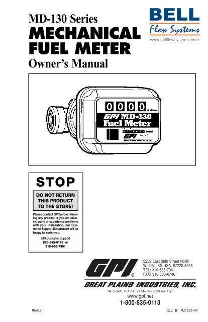
MD-130 Series<br />
<strong>MECHANICAL</strong><br />
<strong>FUEL</strong> <strong>METER</strong><br />
Owner’s Manual<br />
www.bellflowsystems.com<br />
5252 East 36th Street North<br />
Wichita, KS USA 67220-3205<br />
TEL: 316-686-7361<br />
FAX: 316-686-6746<br />
06/05<br />
“A Great Plains Ventures Subsidiary”<br />
www.gpi.net<br />
1-800-835-0113<br />
Rev. B 921523-09
TABLE OF CONTENTS<br />
General Information ............................... 1<br />
Installation .............................................. 1<br />
Operation ................................................ 2<br />
Calibration .............................................. 2<br />
Maintenance ........................................... 3<br />
Troubleshooting ..................................... 4<br />
Specifications ......................................... 4<br />
Illustrated Parts List ............................... 5<br />
Parts and Service .................................... 6<br />
Great Plains Industries, Inc. is a member of the<br />
Petroleum Equipment Institute.<br />
GENERAL INFORMATION<br />
Congratulations on receiving your new<br />
meter. This manual should assist you in<br />
operating and maintaining your mechanical<br />
fuel meter. Please take a few moments<br />
to read these instructions before installing<br />
and operating your fuel meter. If you need<br />
assistance, contact the dealer from whom<br />
you purchased your meter. If you need further<br />
assistance, please call our Customer<br />
Service Department at 1-800-835-0113.<br />
Safety Instructions<br />
Please read, understand, and follow the<br />
safety instructions given here. It is your responsibility<br />
to ensure that all equipment<br />
operators have access to adequate instructions<br />
concerning safe operation and maintenance.<br />
1. This meter is designed for use only<br />
with thin viscosity petroleum fuels<br />
such as gasoline, diesel fuel, and kerosene.<br />
Gasoline includes up to 15% alcohol<br />
blends.<br />
2. Do not use this equipment for dispensing<br />
any fluids other than those for<br />
which it was designed. To do so may<br />
damage the meter and will void the<br />
warranty.<br />
1<br />
3. Observe precautions against fire or<br />
explosion when dispensing fuel. Do<br />
not operate the meter in the presence<br />
of any source of ignition including running<br />
or hot engines, lighted cigarettes,<br />
or gas or electric heaters.<br />
4. Any components such as hose, nozzle,<br />
or pump added to your meter must be<br />
statically grounded and approved for<br />
use with petroleum fuels.<br />
5. Avoid prolonged skin contact with<br />
petroleum fuels. Use protective goggles,<br />
gloves, and aprons in case of accidental<br />
splashing or spillage. Change<br />
saturated clothing and wash skin contact<br />
areas promptly with soap and water.<br />
The MD-130 Series of Mechanical Fuel<br />
Meters are designed for the field measurement<br />
of thin viscosity petroleum fuels<br />
only and are intended for use with pump<br />
systems in the 5 to 30 GPM or 19 to 114<br />
LPM flow range (not intended for gravity<br />
flow systems). Using mechanical<br />
gears, these meters translate flow data from<br />
a nutating disc into calibrated units which<br />
are indicated on the face of the meter. This<br />
meter is factory calibrated for diesel fuel.<br />
Field calibration feature is available for<br />
other fluids, see Calibration section.<br />
INSTALLATION<br />
Before installing your meter, review the<br />
safety instructions given above. Examine<br />
your meter to make sure there are no visible<br />
signs of shipment damage. Plan your<br />
meter installation by reviewing the following<br />
procedures. Your system must be<br />
mounted on a vented tank. If the tank is<br />
unvented, your local dealer or distributor can<br />
supply a pressure cap.<br />
Prior to installation, determine the fitting<br />
angle desired and whether horizontal or<br />
vertical orientation is required.<br />
Rotate Fittings<br />
To rotate inlet and/or outlet fittings, remove<br />
the two nuts and bolts which secure each<br />
fitting. Rotate the fitting to the desired orientation.<br />
Make sure the O-ring is fully<br />
seated. Tighten the nuts and bolts snugly.
Change Orientation<br />
1. Remove the two Phillips head screws<br />
which secure the cover to the<br />
coverplate assembly.<br />
2. Remove the eight pairs of nuts and<br />
bolts which hold the coverplate assembly<br />
to the housing. (Figure 1) Note the<br />
position of the reset button.<br />
Figure 1<br />
Tite thread sealant is recommended at the<br />
inlet fitting.<br />
3. Install the meter on the pump using an<br />
appropriately sized nipple. The meter’s<br />
flow path is marked on the housing<br />
exterior with an arrow pointing toward<br />
the outlet port.<br />
4. Install other system components on the<br />
meter and tighten snugly.<br />
OPERATION<br />
3. Rotate the coverplate assembly and<br />
counter to the desired orientation.<br />
Make sure the flow arrow in the<br />
housing points toward the outlet port.<br />
(Figure 2)<br />
Before use, review the safety instructions<br />
given above. Visually check the meter to<br />
ensure it is securely connected to other system<br />
components and there is no leakage.<br />
Promptly wipe spilled fuel from the meter’s<br />
exterior and other system components.<br />
The large meter display represents the<br />
Batch Total for each fuel delivery. Before<br />
dispensing, reset the Batch Total to zero<br />
by pushing the reset button. (Figure 3)<br />
Figure 3<br />
Figure 2<br />
4. Make sure the housing O-ring is fully<br />
seated and firmly tighten the eight nuts<br />
and bolts which secure the coverplate<br />
assembly.<br />
5. Place the reset button in position. Secure<br />
the cover to the coverplate assembly<br />
with the two Phillips head screws.<br />
Meter Installation<br />
1. Remove protective plugs from the<br />
meter inlet and outlet ports.<br />
2. Wrap threaded male connections with<br />
Teflon ® tape or use a pipe sealant compound<br />
compatible with petroleum<br />
fuels. With horizontal orientation, Lock-<br />
The small display represents the Cumulative<br />
Total of all fuel deliveries and cannot<br />
be reset.<br />
CALIBRATION<br />
The meter is accurately calibrated at the<br />
factory for use with diesel fuel. Due to differences<br />
in viscosity and flow rates, the<br />
meter may require recalibration to measure<br />
other fuels or to adjust for inaccuracies.<br />
1. Purge air from the meter and fuel system<br />
by dispensing fuel into a container<br />
until a full flow occurs. Close the<br />
nozzle.<br />
2
2. Reset the meter counter to zero by<br />
pressing the reset button. (Figure 3)<br />
3. Pump into a graduated calibration container<br />
to a specified quantity. For the<br />
greatest accuracy, be sure the container<br />
is placed on a level surface and a consistent<br />
flow rate is used. When topping<br />
off the calibration container, use a<br />
quick-open and quick-close method<br />
until the mark is reached.<br />
NOTE: Your GPI dealer can supply a calibration<br />
container designed for this purpose.<br />
(Figure 4)<br />
Figure 4<br />
b. If the meter registered less than the<br />
quantity in the container, turn the<br />
calibration screw clockwise. If the<br />
meter display read more than the<br />
amount in the container, turn the<br />
calibration screw counterclockwise.<br />
5. Empty the calibration container and<br />
repeat steps 2 to 4 until the meter registers<br />
the quantity in the container.<br />
6. Install the nylon washer and calibration<br />
screw cover.<br />
MAINTENANCE<br />
The meter’s strainer should be cleaned at<br />
regular intervals, especially when low flow<br />
is detected.<br />
4. Compare the meter display to the quantity<br />
in the container. If the display does<br />
not register the quantity on the container,<br />
adjust the meter by performing<br />
the following:<br />
a. Gain access to the recessed calibration<br />
screw by turning the calibration<br />
screw cover and seal counterclockwise.<br />
Remove the cover and<br />
nylon washer. (Figure 5)<br />
Clean or Replace Strainer<br />
1. Remove the nuts and bolts at the inlet<br />
fitting. Remove the fitting, O-ring, and<br />
strainer.<br />
2. Using a fine brush, clean the strainer.<br />
Replace the strainer as necessary.<br />
3. Wipe clean the inlet, housing, and<br />
O-ring groove. Coat the O-ring with<br />
oil or light grease. Make sure the O-ring<br />
is fully seated. Replace the strainer.<br />
4. Position the inlet fitting in the desired<br />
orientation and tighten the nuts and<br />
bolts until snug.<br />
Figure 5<br />
3
TROUBLESHOOTING<br />
Symptom Probable Cause Corrective Action<br />
A. Meter counter does 1. Broken counter assembly. Replace counter.<br />
not operate. (Normal<br />
fuel delivery)<br />
2. Foreign material in counter Remove and clean counter<br />
assembly or nutator assembly. assembly or nutator assembly.<br />
3. Broken nutator disc pin or Install new nutator assembly.<br />
defective nutator assembly.<br />
4. Jammed or broken gear train. Contact GPI Customer Service.<br />
B. Meter counter does 1. Clogged strainer in meter. Clean or replace strainer.<br />
not operate. (Little<br />
2. Other system components Check all system components<br />
or no fuel flow)<br />
malfunctioning.<br />
from tank to nozzle for clogs<br />
and/or malfunctions. Repair as<br />
necessary.<br />
3. Foreign material in nutator Remove and clean nutator<br />
assembly.<br />
assembly.<br />
C. Fuel leakage. 1. Leakage at counter drive shaft. Replace coverplate assembly.<br />
2. Leakage between coverplate and Remove coverplate and inspect<br />
housing.<br />
for damaged, missing or<br />
incorrectly seated seal. Replace<br />
as required.<br />
3. Leakage at fittings. Remove fittings and inspect for<br />
damaged, missing or incorrectly<br />
seated seals. Replace as required.<br />
4. Leakage at threads. Remove meter and reseal all<br />
threaded connections with<br />
Teflon ® tape or pipe thread<br />
sealing compound approved<br />
for use with flammable liquids.<br />
SPECIFICATIONS<br />
Gallon Models Litre Models<br />
Unit of Measure U.S. Gallon Litre<br />
<strong>Flow</strong> Range 5 to 30 GPM 19 to 114 LPM<br />
Typical Accuracy ± 2% ± 2%<br />
Type Nutating Disc Nutating Disc<br />
Housing Material Aluminum Aluminum<br />
Maximum Working Pressure 50 PSIG 3.4 bar<br />
Inlet/Outlet Fitting Size 3/4", 1" or 1-1/2" 3/4", 1" or 1-1/2"<br />
Threads NPT NPT or BSPP<br />
Maximum Batch Total 999.9 9999<br />
Maximum Cumulative Total 999,999.9 9,999,999<br />
Approximate Ship Weight 6.0 lbs. 2.7 kg<br />
Maximum Dimensions: Width: 8.7 inches 22 cm<br />
Height: 5.9 inches 15 cm<br />
Depth: 5.7 inches 14.5 cm<br />
Note: Accuracy is factory calibrated using diesel fuel. Field Calibration is available on all models.<br />
4
5<br />
ILLUSTRATED PARTS LIST
ILLUSTRATED PARTS LIST<br />
Item<br />
No.<br />
No. Part No. Description Req’d.<br />
1 126152-01 Counter Assembly, Gallons ............................................... 1<br />
126152-02 Counter Assembly, Litres .................................................. 1<br />
2 126154-01 Coverplate Assembly ......................................................... 1<br />
3 126010-1 Housing .............................................................................. 1<br />
4 126013-11 Top Cover........................................................................... 1<br />
5 126151-01 Decal (Gallon) ................................................................... 1<br />
126151-03 Decal (Litre)....................................................................... 1<br />
items not shown:<br />
111014-3 Calibration Screw .............................................................. 1<br />
111026-1 Seal, Calibration Screw ..................................................... 1<br />
111039-2 Cover, Calibration Screw .................................................. 1<br />
904006-16 Washer, Calibration Screw Cover ..................................... 1<br />
Kits and Accessories<br />
A 126514-01 Gear Assembly Kit, Gallons<br />
126514-02 Gear Assembly Kit, Litres<br />
B 126503-1 Nutator Assembly Kit<br />
C 126509-1 Seal Kit (Housing O-Ring, Fitting O-Rings)<br />
D 126512-1 Hardware Kit (Fitting O-Rings, Strainer, Screws, Nuts)<br />
E 126501-1 Fitting Kit for 3/4-inch NPT (2 Fittings, 2 Fitting O-Rings)<br />
126501-2 Fitting Kit for 3/4-inch BSPP (2 Fittings, 2 Fitting O-Rings)<br />
126501-3 Fitting Kit for 1-inch NPT (2 Fittings, 2 Fitting O-Rings)<br />
126501-4 Fitting Kit for 1-inch BSPP (2 Fittings, 2 Fitting O-Rings)<br />
126501-5 Fitting Kit for 1-1/2-inch NPT (2 Fittings, 2 Fitting O-Rings)<br />
126501-6 Fitting Kit for 1-1/2-inch BSPP (2 Fittings, 2 Fitting O-Rings)<br />
PARTS AND SERVICE<br />
For warranty consideration, parts, or other<br />
service information, contact your local distributor.<br />
If you need further assistance,<br />
please contact GPI Customer Service Department<br />
in Wichita, Kansas during normal<br />
business hours at 1-800-835-0113.<br />
To obtain prompt, efficient service, always<br />
be prepared with 1.) the model number of<br />
your meter, 2.) the manufacturing date located<br />
on the back of the meter, and 3.) specific<br />
information, as necessary, obtained<br />
from the Illustrated Parts List. For warranty<br />
work always be prepared with proof of purchase<br />
date.<br />
Please contact GPI before returning any<br />
parts. It may be possible to diagnose the<br />
trouble and identify needed parts without<br />
returning parts. GPI can also inform you<br />
of any special handling requirements you<br />
will need to follow covering the transportation<br />
and handling of fuel transfer equipment.<br />
Before packing for shipment, make<br />
sure the meter is thoroughly drained and<br />
free of fuel and vapors.<br />
CAUTION! Do not return meters or parts<br />
without specific authority from the GPI<br />
Customer Service Department. Due to<br />
strict regulations governing shipment<br />
of flammable liquids, meters may be<br />
refused and returned to the sender if<br />
sent without authorization.<br />
6
Limited Warranty Policy<br />
Great Plains Industries, Inc. 5252 E. 36 th Street North, Wichita, KS USA 67220-3205, hereby provides a<br />
limited warranty against defects in material and workmanship on all products manufactured by Great Plains<br />
Industries, Inc. This product includes a 2 year warranty. Manufacturer’s sole obligation under the foregoing<br />
warranties will be limited to either, at Manufacturer’s option, replacing or repairing defective Goods (subject<br />
to limitations hereinafter provided) or refunding the purchase price for such Goods theretofore paid by the<br />
Buyer, and Buyer’s exclusive remedy for breach of any such warranties will be enforcement of such obligations<br />
of Manufacturer. The warranty shall extend to the purchaser of this product and to any person to whom<br />
such product is transferred during the warranty period.<br />
The warranty period shall begin on the date of manufacture or on the date of purchase with an original sales<br />
receipt. This warranty shall not apply if:<br />
A. the product has been altered or modified outside the warrantor’s duly appointed representative;<br />
B. the product has been subjected to neglect, misuse, abuse or damage or has been installed or operated<br />
other than in accordance with the manufacturer’s operating instructions.<br />
To make a claim against this warranty, contact the GPI Customer Service Department at 316-686-7361 or<br />
800-835-0113. Or by mail at:<br />
Great Plains Industries, Inc.<br />
5252 E. 36 th St. North<br />
Wichita, KS, USA 67220-3205<br />
The company shall, notify the customer to either send the product, transportation prepaid, to the company at<br />
its office in Wichita, Kansas, or to a duly authorized service center. The company shall perform all obligations<br />
imposed on it by the terms of this warranty within 60 days of receipt of the defective product.<br />
GREAT PLAINS INDUSTRIES, INC., EXCLUDES LIABILITY UNDER THIS WARRANTY FOR DIRECT,<br />
INDIRECT, INCIDENTAL AND CONSEQUENTIAL DAMAGES INCURRED IN THE USE OR LOSS OF<br />
USE OF THE PRODUCT WARRANTED HEREUNDER.<br />
The company herewith expressly disclaims any warranty of merchantability or fitness for any particular purpose<br />
other than for which it was designed.<br />
This warranty gives you specific rights and you may also have other rights which vary from U.S. state to U.S.<br />
state.<br />
Note: In compliance with MAGNUSON MOSS CONSUMER WARRANTY ACT – Part 702 (governs the<br />
resale availability of the warranty terms).<br />
5252 East 36th Street North<br />
Wichita, KS USA 67220-3205<br />
TEL: 316-686-7361<br />
FAX: 316-686-6746<br />
GPI is a registered trademark of Great Plains Industries, Inc.<br />
© 2005 GREAT PLAINS INDUSTRIES, INC., Wichita, KS.<br />
Printed in U.S.A.<br />
06/05<br />
“A Great Plains Ventures Subsidiary”<br />
www.gpi.net<br />
1-800-835-0113<br />
Rev. B 921523-09