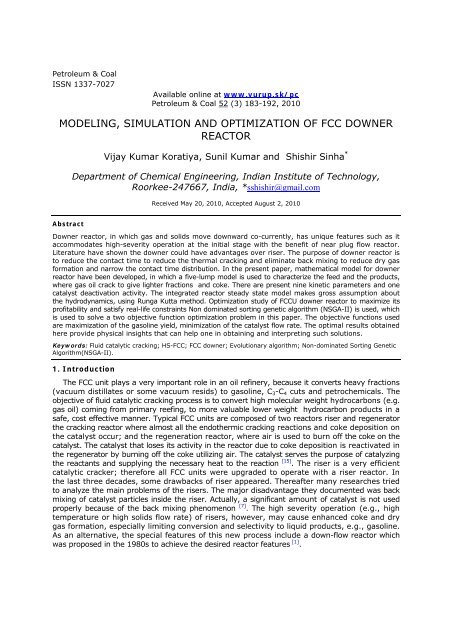
modeling, simulation and optimization of fcc downer reactor
modeling, simulation and optimization of fcc downer reactor
modeling, simulation and optimization of fcc downer reactor

You also want an ePaper? Increase the reach of your titles
YUMPU automatically turns print PDFs into web optimized ePapers that Google loves.
Petroleum & Coal<br />
ISSN 1337-7027<br />
Available online at www.vurup.sk/pc<br />
Petroleum & Coal 52 (3) 183-192, 2010<br />
MODELING, SIMULATION AND OPTIMIZATION OF FCC DOWNER<br />
REACTOR<br />
Vijay Kumar Koratiya, Sunil Kumar <strong>and</strong> Shishir Sinha *<br />
Department <strong>of</strong> Chemical Engineering, Indian Institute <strong>of</strong> Technology,<br />
Roorkee-247667, India, *sshishir@gmail.com<br />
Received May 20, 2010, Accepted August 2, 2010<br />
Abstract<br />
Downer <strong>reactor</strong>, in which gas <strong>and</strong> solids move downward co-currently, has unique features such as it<br />
accommodates high-severity operation at the initial stage with the benefit <strong>of</strong> near plug flow <strong>reactor</strong>.<br />
Literature have shown the <strong>downer</strong> could have advantages over riser. The purpose <strong>of</strong> <strong>downer</strong> <strong>reactor</strong> is<br />
to reduce the contact time to reduce the thermal cracking <strong>and</strong> eliminate back mixing to reduce dry gas<br />
formation <strong>and</strong> narrow the contact time distribution. In the present paper, mathematical model for <strong>downer</strong><br />
<strong>reactor</strong> have been developed, in which a five-lump model is used to characterize the feed <strong>and</strong> the products,<br />
where gas oil crack to give lighter fractions <strong>and</strong> coke. There are present nine kinetic parameters <strong>and</strong> one<br />
catalyst deactivation activity. The integrated <strong>reactor</strong> steady state model makes gross assumption about<br />
the hydrodynamics, using Runga Kutta method. Optimization study <strong>of</strong> FCCU <strong>downer</strong> <strong>reactor</strong> to maximize its<br />
pr<strong>of</strong>itability <strong>and</strong> satisfy real-life constraints Non dominated sorting genetic algorithm (NSGA-II) is used, which<br />
is used to solve a two objective function <strong>optimization</strong> problem in this paper. The objective functions used<br />
are maximization <strong>of</strong> the gasoline yield, minimization <strong>of</strong> the catalyst flow rate. The optimal results obtained<br />
here provide physical insights that can help one in obtaining <strong>and</strong> interpreting such solutions.<br />
Keywords: Fluid catalytic cracking; HS-FCC; FCC <strong>downer</strong>; Evolutionary algorithm; Non-dominated Sorting Genetic<br />
Algorithm(NSGA-II).<br />
1. Introduction<br />
The FCC unit plays a very important role in an oil refinery, because it converts heavy fractions<br />
(vacuum distillates or some vacuum resids) to gasoline, C 3 -C 4 cuts <strong>and</strong> petrochemicals. The<br />
objective <strong>of</strong> fluid catalytic cracking process is to convert high molecular weight hydrocarbons (e.g.<br />
gas oil) coming from primary reefing, to more valuable lower weight hydrocarbon products in a<br />
safe, cost effective manner. Typical FCC units are composed <strong>of</strong> two <strong>reactor</strong>s riser <strong>and</strong> regenerator<br />
the cracking <strong>reactor</strong> where almost all the endothermic cracking reactions <strong>and</strong> coke deposition on<br />
the catalyst occur; <strong>and</strong> the regeneration <strong>reactor</strong>, where air is used to burn <strong>of</strong>f the coke on the<br />
catalyst. The catalyst that loses its activity in the <strong>reactor</strong> due to coke deposition is reactivated in<br />
the regenerator by burning <strong>of</strong>f the coke utilizing air. The catalyst serves the purpose <strong>of</strong> catalyzing<br />
the reactants <strong>and</strong> supplying the necessary heat to the reaction [15] . The riser is a very efficient<br />
catalytic cracker; therefore all FCC units were upgraded to operate with a riser <strong>reactor</strong>. In<br />
the last three decades, some drawbacks <strong>of</strong> riser appeared. Thereafter many researches tried<br />
to analyze the main problems <strong>of</strong> the risers. The major disadvantage they documented was back<br />
mixing <strong>of</strong> catalyst particles inside the riser. Actually, a significant amount <strong>of</strong> catalyst is not used<br />
properly because <strong>of</strong> the back mixing phenomenon [7] . The high severity operation (e.g., high<br />
temperature or high solids flow rate) <strong>of</strong> risers, however, may cause enhanced coke <strong>and</strong> dry<br />
gas formation, especially limiting conversion <strong>and</strong> selectivity to liquid products, e.g., gasoline.<br />
As an alternative, the special features <strong>of</strong> this new process include a down-flow <strong>reactor</strong> which<br />
was proposed in the 1980s to achieve the desired <strong>reactor</strong> features [1] .
V. K. Koratiya, S. Kumar, S. Sinha/Petroleum & Coal 52(3) 183-192, 2010 184<br />
1.1 High-Severity FCC Process<br />
High-Severity Fluid catalytic cracking (HS-FCC) is a new process for the conversion <strong>of</strong> heavy<br />
oils into lighter hydrocarbon products <strong>and</strong> petrochemical feed stocks. Research teams from<br />
Japan <strong>and</strong> Saudi Arabia are jointly developing this technology. The process combines mechanical<br />
modifications to conventional FCC with changes in process variables <strong>and</strong> catalyst formulations.<br />
The main operating regime <strong>of</strong> the process is a special down-flow <strong>reactor</strong> system, high reaction<br />
temperature, short contact time, <strong>and</strong> high catalyst/oil ratio. The HS-FCC project shared between<br />
KFUPM petroleum energy Centre – Japan (PEC) aims to construct a pilot plant as shown in<br />
fig.1., which will give valuable information to prove whether the <strong>downer</strong> is better than the<br />
riser or not. Moreover, Nippon Oil Company , Japan, is also installing a cold model as<br />
demonstration unit for FCC <strong>downer</strong> process in Japan.<br />
1.2 Downer <strong>reactor</strong><br />
Fig.1 High-Severity FCC Process [8]<br />
A typical <strong>downer</strong> <strong>reactor</strong> consists <strong>of</strong> a vertical column (usually <strong>of</strong> circular cross-section,<br />
but sometimes square or rectangular) with gas <strong>and</strong> solids distributors at the top <strong>and</strong> one or<br />
more gas-solids separator at the bottom. For catalytic reactions, or gas phase reactions with<br />
solids as heat carriers, solids are recirculated to the top <strong>of</strong> the <strong>downer</strong> after regeneration or<br />
re-heating. In this new <strong>reactor</strong> gas <strong>and</strong> solids move vertically downward in the direction <strong>of</strong><br />
gravity, the radial gas <strong>and</strong> solids flow structures are much more uniform compared to other<br />
gas–solids fluidized bed <strong>reactor</strong>s, e.g., bubbling bed, turbulent bed <strong>and</strong> riser. Recent studies<br />
about <strong>downer</strong> <strong>reactor</strong>s showed that almost plug flow <strong>of</strong> the solids can be achieved with FCC<br />
particles. However, the radial solids distribution still shows higher solids concentrations in<br />
the wall region compared to the core region [13,15,16] . Downer is therefore acknowledged as a<br />
novel multiphase flow <strong>reactor</strong> with great potential in high-severity operated processes, such<br />
as the high temperature, ultra-short contact time reactions with the intermediates as the<br />
desired products.<br />
2. MODEL DEVELOPMENT<br />
The HS- FCC process is similar to the conventional FCC. It consists <strong>of</strong> three components,<br />
a <strong>downer</strong> <strong>reactor</strong>, a catalyst stripper <strong>and</strong> a regenerator. In this model, the stripper role is not<br />
considered because it does not change the heat or the mass <strong>of</strong> the spent catalyst stripped
V. K. Koratiya, S. Kumar, S. Sinha/Petroleum & Coal 52(3) 183-192, 2010 185<br />
from the product <strong>of</strong> the <strong>downer</strong> <strong>reactor</strong>. This unit deals with two <strong>reactor</strong>s. First the <strong>downer</strong><br />
<strong>reactor</strong> where the gasoil <strong>and</strong> catalyst are fed from the top <strong>of</strong> the <strong>downer</strong> causing the endothermic<br />
cracking reactions to occur.<br />
2.1 DOWNER KINETICS<br />
For the <strong>modeling</strong> <strong>of</strong> the <strong>downer</strong> <strong>reactor</strong> many schemes are proposed. Here [4] five lump<br />
scheme has been considered for present study. The below fig.2 represent the schematic<br />
diagram <strong>of</strong> the five –lump model.<br />
Gas Oil<br />
Gasoline<br />
k 1<br />
k 4 k 5<br />
k 7 k 6<br />
k 2 k 3<br />
Coke LPG Dry Gas<br />
k 9 k 8<br />
Fig. 2 Schematic diagram <strong>of</strong> the five-lump<br />
For each reaction, a kinetic expression (ri) was formulated as a function <strong>of</strong> product yield<br />
(yi), deactivation function (φ) <strong>and</strong> kinetic constants (ki). Gas oil cracking was considered as<br />
a second order reaction <strong>and</strong> gasoline <strong>and</strong> LPG as first order [2] . The use <strong>of</strong> first order reaction<br />
for cracking <strong>of</strong> LPG has been discussed in the literature [9] . The exponential law was<br />
assumed for catalyst decay (φ). Based on these assumptions, the reaction rates for the five<br />
lumps are as follows:<br />
(1)<br />
(2)<br />
(3)<br />
(4)<br />
2.2 DOWNER REACTOR MODELLING<br />
1. Both catalyst <strong>and</strong> feed oil is charged in to the upper part <strong>of</strong> the <strong>downer</strong> <strong>reactor</strong>.<br />
Instantaneous vaporization <strong>of</strong> feed oil occurs by taking latent heat <strong>and</strong> sensible heat<br />
from the hot catalyst. Thus feed oil <strong>and</strong> catalyst are in thermal equilibrium.<br />
2. There is no loss <strong>of</strong> heat from the <strong>downer</strong> <strong>and</strong> the temperature <strong>of</strong> the reaction mixture<br />
(vapor +catalyst) falls only because <strong>of</strong> endothermicity <strong>of</strong> cracking reaction.<br />
3. Plug flow behavior is assumed for the <strong>downer</strong> according to the survey <strong>of</strong> hydrodynamics<br />
studies.<br />
4. The changes due to molar expansion were not accounted. Thus the molar volume <strong>of</strong><br />
hydrocarbons is constant along the <strong>downer</strong>. This assumption simplifies the derivations <strong>of</strong><br />
the equation by justifiable idea as proved by [12] .<br />
5. The role <strong>of</strong> steam used to disperse the feed at the entrance <strong>of</strong> <strong>downer</strong> is neglected due to<br />
its low amount compared with the feed. Its percentage in the fed is about 2%.<br />
(5)
V. K. Koratiya, S. Kumar, S. Sinha/Petroleum & Coal 52(3) 183-192, 2010 186<br />
6. Vapor phase <strong>and</strong> solid mass flow rate are constant <strong>and</strong> independent <strong>of</strong> position. Likewise,<br />
the gases void fraction is assumed constant <strong>and</strong> independent <strong>of</strong> position.<br />
7. The <strong>downer</strong> has high combined stream velocity <strong>and</strong> very short residence time. Thus, it<br />
can be assumed that the dynamic term due to vapor phase concentration , coke<br />
formation <strong>and</strong> <strong>downer</strong> temperature in the regenerator. Therefore the mass <strong>and</strong> energy<br />
balance equations are considered at steady state.<br />
8. Heat <strong>and</strong> mass transfer resistances are assumed as negligible.<br />
9. There are no radial temperature gradient in gas & solid phase.<br />
10. Catalyst deactivation follows the [14] which is non selection <strong>and</strong> related to coke on<br />
catalyst only.<br />
11. Gas oil cracking is a second order reaction but cracking <strong>of</strong> gasoline <strong>and</strong> LPG are first<br />
order reaction.<br />
12. Heat <strong>of</strong> reaction are assumed constant. Other thermal <strong>and</strong> physical properties are also<br />
assumed constant (heat capacities <strong>and</strong> densities ) through the length <strong>of</strong> <strong>reactor</strong>.<br />
On the basis <strong>of</strong> above discussion, the mole balance for the j th lump over a differential<br />
element for <strong>downer</strong> <strong>reactor</strong> model can be written as follows :<br />
dF<br />
9<br />
j<br />
= −AdowH<br />
dow ρ φ∑α<br />
ij<br />
( −ri<br />
) j = 1, 2, …….5 (6)<br />
dh<br />
C<br />
i=<br />
1<br />
Where j = 1 to 5 represents gas oil, gasoline, LPG, dry gas, <strong>and</strong> coke respectively. i = 1 to 9<br />
represents the reactions as shown in Fig.2The rate equation in (kmol)/m3(s) are given by<br />
following ex expressions:<br />
5<br />
MW<br />
(7)<br />
g<br />
= ∑ x<br />
j<br />
MW<br />
j<br />
j=<br />
1<br />
E 2<br />
ri<br />
= k0,<br />
i<br />
exp( − ) C1<br />
φ (1 − ε ) ρc<br />
for i = 1,2,3,4 (8)<br />
RT<br />
r<br />
i<br />
r<br />
i<br />
E<br />
= k0,<br />
i<br />
exp( − ) C2φ (1 − ε ) ρc<br />
for i = 5,6,7 (9)<br />
RT<br />
E<br />
= k0,<br />
i<br />
exp( − ) C3φ (1 − ε ) ρc<br />
for i = 8,9 (10)<br />
RT<br />
Where, C 1 , C 2 <strong>and</strong> C 3 are concentration <strong>of</strong> gas oil, gasoline <strong>and</strong> LPG respectively. Other<br />
parameters can formulated as follows<br />
PdowMWg<br />
ρ v =<br />
(11)<br />
RT<br />
MWi<br />
α =<br />
(12)<br />
ij<br />
MW<br />
j<br />
2.3 Catalyst deactivation<br />
Catalyst used for the cracking loses its activity mainly due to following three reason :<br />
(i) Physical change due to coke deposition <strong>and</strong> structural change due to sintering.<br />
(ii) Poisoning due to the presence <strong>of</strong> metals <strong>and</strong> non-metals in FCC feed.<br />
(iii) Deposition <strong>of</strong> coke on the active site.<br />
For the <strong>modeling</strong> <strong>of</strong> the catalyst deactivation the functionφ was related to coke on<br />
catalyst as follows [14] :<br />
−2.78<br />
φ = (1 + 51C<br />
c<br />
)<br />
(13)<br />
2.4 Energy balance around the <strong>downer</strong> <strong>reactor</strong><br />
The energy balance <strong>of</strong> plug flow <strong>reactor</strong> is applied for this model. Due to the endothermic<br />
cracking reactions in the <strong>downer</strong>, there is a temperature drop along the height <strong>of</strong> the
V. K. Koratiya, S. Kumar, S. Sinha/Petroleum & Coal 52(3) 183-192, 2010 187<br />
<strong>downer</strong>. The enthalpy balance across a differential element <strong>of</strong> height dh <strong>of</strong> the <strong>downer</strong> can<br />
be represented as follows:<br />
9<br />
dT − Adow<br />
H<br />
dow<br />
=<br />
∑ r ( Δ )<br />
5<br />
i<br />
H<br />
i<br />
dh<br />
(14)<br />
i=<br />
1<br />
F C + F x C<br />
rgc<br />
P C<br />
∑<br />
feed<br />
i=<br />
1<br />
At the entrance <strong>of</strong> the <strong>downer</strong>:-The regenerated catalyst <strong>and</strong> preheated liquid are mix at the<br />
top <strong>of</strong> the <strong>reactor</strong>. So in order to define mix temperature it is necessary to write an enthalpy<br />
balance equation:-<br />
FrgcCP c<br />
Trgn<br />
+ F<br />
feedCP fl<br />
T<br />
feed+ΔH<br />
evp<br />
F<br />
feed<br />
TM<br />
=<br />
FrgcCP c<br />
+ F<br />
feedCP fvgasoil<br />
(15)<br />
Table 1. Kinetic <strong>and</strong> deactivation parameters for reaction in the <strong>downer</strong> <strong>and</strong> regenerator<br />
used in FCC unit (5-lump) [4]<br />
Rate constant Frequency factor Activation energy<br />
(kJ/kmol)<br />
k1 19584.55 57540<br />
k2 3246.45 52500<br />
k3 559.90 49560<br />
k4 41.44 31920<br />
k5 65.40 73500<br />
k6 0.00 45360<br />
k7 0.00 66780<br />
k8 0.32 39900<br />
k9 0.19 31500<br />
Table 2. Heat <strong>of</strong> reaction <strong>and</strong> vaporization used in the FCC-<strong>downer</strong> <strong>reactor</strong> [4]<br />
Heat <strong>of</strong> reaction Value (kJ/kmol)<br />
H1 45000<br />
H2 159315<br />
H3 159315<br />
H4 159315<br />
H5 42420<br />
i<br />
Table 3. Operational Parameters used to the FCC –<strong>downer</strong> <strong>reactor</strong> unit<br />
Parameters Value Ref<br />
Downer length (m) 5.8-11 m From review<br />
Downer diameter (m) 80mm-150mm From review<br />
Feed flow rate (kg/s) 0.4-1.2<br />
[8]<br />
Feed preheat temperature (K) 523 or 640<br />
[8,17,18]<br />
Regenerator temperature (K) 930.2<br />
[4]<br />
Catalyst flow rate (kg/s) 100-250<br />
[8,17,18]<br />
Downer pressure (atm) 0.079-1.25<br />
[8,17,18]<br />
Table 4. Physical <strong>and</strong> thermal properties used in the <strong>simulation</strong> <strong>of</strong> the FCC <strong>downer</strong> unit<br />
Properties (unit)<br />
value<br />
C P,c (kJ/kg K) 1.108 kJ/ (kg K)<br />
C P,fl (kJ/kg K)<br />
2.10 kj/kg K<br />
C P,fv (kJ/kg K) 2.04<br />
∆H evp (kJ/kg)<br />
270 kJ/ kg<br />
X Pt<br />
0.10(x)<br />
ρ c (kg/m 3 ) 1500<br />
C H (kg H 2 /kg coke) 12-30<br />
P fvi
V. K. Koratiya, S. Kumar, S. Sinha/Petroleum & Coal 52(3) 183-192, 2010 188<br />
3. Optimization<br />
Optimization refers to finding the values <strong>of</strong> decision variables, which correspond to <strong>and</strong><br />
provide the maximum or minimum <strong>of</strong> one or more desired objectives. <strong>optimization</strong> finds many<br />
applications in engineering, science, business, economics, etc. Without <strong>optimization</strong> <strong>of</strong> design<br />
<strong>and</strong> operations, manufacturing <strong>and</strong> engineering activities will not be as efficient as they are<br />
now. Several studies have also been carried out on the <strong>optimization</strong> <strong>of</strong> FCCUs. Most <strong>of</strong> them<br />
use some type <strong>of</strong> a pr<strong>of</strong>it-function as the objective. Some <strong>of</strong> the commonly used decision<br />
variables in these studies are the regenerator temperature, <strong>reactor</strong> temperature, catalyst<br />
circulation rate <strong>and</strong> the air supply rate. Here I am using recent adaptation <strong>of</strong> genetic algorithm<br />
( NSGA-II), as developed by Deb <strong>and</strong> co-workers [6] there are two versions <strong>of</strong> non- dominated<br />
sorting genetic algorithm NSGA [11] <strong>and</strong> the elitist NSGA-II [6] . These two adaptations <strong>of</strong> NSGA<br />
have been used extensively to solve a variety <strong>of</strong> multi-objective <strong>optimization</strong> problems in<br />
chemical engineering. The applications <strong>of</strong> NSGA (<strong>and</strong> other techniques) in chemical engineering<br />
have been reviewed by [3] while those <strong>of</strong> NSGA-II have been reviewed by [10] , the latter for<br />
problems in chemical reaction engineering.<br />
3.1General description <strong>of</strong> NSGA-II<br />
(i) Population initialization<br />
The population is initialized based on the problem range <strong>and</strong> constraints if any.<br />
(ii) Non-Dominated sort<br />
Once the population is initialized the population is sorted based on non-dominant set in<br />
the current population <strong>and</strong> the second front being dominated by the individuals in the first<br />
front only <strong>and</strong> the front goes so on.<br />
(iii) Crowding distance<br />
Once the non-dominated sort is complete, the crowding distance is assigned. Since the<br />
individuals are selected based on rank <strong>and</strong> crowding distance, all the individuals in the population<br />
are assigned a crowding distance value. Crowding distance is assigned front wise <strong>and</strong> comparing<br />
the crowding distance between two different fronts is meaningless.<br />
(iv) Selection<br />
Once the individuals are sorted based on non-domination <strong>and</strong> with crowding distance<br />
assigned, the selection is carried out using a crowded-comparison-operator ( n).<br />
(v) Recombination <strong>and</strong> selection<br />
The <strong>of</strong>fspring population is combined with the current generation population <strong>and</strong> selection<br />
is performed to set the individuals <strong>of</strong> the next generation. Since all the previous <strong>and</strong> current<br />
best individuals are added in the population, elitism is ensured. Population is now sorted based on<br />
non-domination. The new generation is filled by each front subsequently until the population<br />
size exceeds the current population size. If by adding all the individuals in front Fj the population<br />
exceeds N then individuals in front Fi are selected based on their crowding distance in the<br />
descending order until the population size is N. And hence the process repeats to generate<br />
the subsequent generations.<br />
4. RESULT AND DISSCUSION<br />
This section discusses the results obtained by <strong>simulation</strong> <strong>and</strong> <strong>optimization</strong> <strong>of</strong> FCCU<br />
<strong>downer</strong>. This section is organized into two parts:<br />
1. Optimization <strong>of</strong> FCCU <strong>downer</strong> <strong>reactor</strong>.<br />
2. Simulation <strong>of</strong> model equations for a <strong>downer</strong> <strong>reactor</strong>.<br />
4.1 Optimization <strong>of</strong> FCCU <strong>downer</strong> <strong>reactor</strong><br />
Following Figures show the plot between the two objective functions:<br />
(i) Maximization <strong>of</strong> gasoline yield<br />
(ii) Minimization <strong>of</strong> catalyst flow rate<br />
The population size was 100 <strong>and</strong> the max. number <strong>of</strong> generation was taken as 200 (min.<br />
zero <strong>and</strong> max. 200).the computer time was about 72 hr. It can be observed from figures<br />
that every point on the pareto surface is non dominating because any point may be good<br />
than other in terms <strong>of</strong> two objective function.
V. K. Koratiya, S. Kumar, S. Sinha/Petroleum & Coal 52(3) 183-192, 2010 189<br />
Table 5. Parameters <strong>and</strong> bounds used in <strong>optimization</strong><br />
Parameter<br />
Value<br />
Population size 100<br />
Probability <strong>of</strong> crossover 0.95<br />
Probability <strong>of</strong> mutation 0.05<br />
R<strong>and</strong> state 0<br />
Maximum generation 200<br />
Bounds:<br />
575 K < Feed preheat temperature < 640 K;<br />
126 kg/sec < Catalyst flow rate in first <strong>reactor</strong> < 315 kg/sec;<br />
0.38 kmole/sec < Air flow rate
V. K. Koratiya, S. Kumar, S. Sinha/Petroleum & Coal 52(3) 183-192, 2010 190<br />
It can be easily inferred from Figure 4 that the catalyst flow rate in <strong>downer</strong> <strong>reactor</strong><br />
should be always maintained close to the lower bound <strong>and</strong> it is also inferred that the<br />
gasoline yield constant up to some extant then it is slowly increases with increase in catalyst<br />
flow rate in <strong>reactor</strong>. Therefore, to minimize the catalyst flow rate we should maintain the<br />
catalyst flow rate close to the lower bound in <strong>reactor</strong>. From the optimized data it was also<br />
observed that feed preheat temperature <strong>and</strong> air flow rate should be maintained close to<br />
upper bounds <strong>and</strong> air preheat temperature should be maintained between 150 K <strong>and</strong> 425K.<br />
4.2 Simulation <strong>of</strong> model equations for a <strong>downer</strong> <strong>reactor</strong><br />
Model equations for single stage riser developed by [4] were simulated. Fig.5 shows the<br />
formation <strong>of</strong> products from gasoil along the length <strong>of</strong> the <strong>downer</strong>. Fig.6 shows the<br />
temperature pr<strong>of</strong>ile inside the <strong>downer</strong>. .<br />
Fig. 5. Formation <strong>of</strong> products from gasoil along the length <strong>of</strong> <strong>downer</strong><br />
Fig. 6. Temperature pr<strong>of</strong>ile along the length <strong>of</strong> <strong>downer</strong><br />
From table 5 it is observed that the gasoline yield 39.68 % for <strong>downer</strong> <strong>reactor</strong> <strong>and</strong> it was<br />
also observed that the temperature inside the <strong>downer</strong> <strong>and</strong> regenerator was more compared<br />
to that <strong>of</strong> single stage FCCU. It was also observed that this increase in gasoline yield was<br />
obtained at the cost <strong>of</strong> increased catalyst rate, increased feed preheat <strong>and</strong> the temperature<br />
<strong>of</strong> bottom <strong>of</strong> the <strong>reactor</strong> is 623 K . Remaining results are tabulated as follows:
V. K. Koratiya, S. Kumar, S. Sinha/Petroleum & Coal 52(3) 183-192, 2010 191<br />
Table 5. Simulation Results for <strong>downer</strong> <strong>reactor</strong><br />
Parameters<br />
Results<br />
Feed flow rate (kg/s) 1.2<br />
Feed preheat temperature (K) 640<br />
Catalyst flow rate (kg/s) 214.16<br />
Downer pressure (atm.) 0.0950<br />
Downer bottom temperature (K) 623.43<br />
Gas oil (unconverted) (%) 40.16<br />
Gasoline (%) 39.68<br />
LPG (%) 13.76<br />
Dry gas (%) 4.174<br />
Coke (%) 2.226<br />
5. Conclusion<br />
In this work, we have presented model equations for an FCC <strong>downer</strong>-type unit. The<br />
results support the fact that in the <strong>downer</strong>, backmixing is eliminated <strong>and</strong> the overcracking <strong>of</strong><br />
intermediate products is suppressed. At high severity conditions, a favorable shift in the<br />
product yields is obtained by <strong>downer</strong>; gasoline yield is increased, coke <strong>and</strong> dry gas yields are<br />
decreased. Though the light olefins yield is lower in case <strong>of</strong> <strong>downer</strong>, the total yield <strong>of</strong> useful<br />
products (gasoline+light olefins) is higher in <strong>downer</strong> as compared to the same from a riser.<br />
The increased yield <strong>of</strong> gasoline form <strong>downer</strong> can be converted to light olefins .<br />
It was also observed that this increase in gasoline yield was obtained at the cost <strong>of</strong><br />
increased catalyst rate, increased feed preheat <strong>and</strong> air preheat temperatures <strong>and</strong> increased<br />
regenerator pressure. Therefore, a cost analysis <strong>of</strong> operating cost <strong>and</strong> pr<strong>of</strong>it from production<br />
<strong>of</strong> excess gasoline is required.<br />
Nomenclature<br />
A dow cross-sectional area <strong>of</strong> <strong>downer</strong>, m 2<br />
C c coke on catalyst at any location, (kg <strong>of</strong> coke) (kg <strong>of</strong> catalyst) -1<br />
C i concentration <strong>of</strong> i th lump, kmol m -3<br />
C pc heat capacity <strong>of</strong> catalyst, kJ kg -1 K -1<br />
C pfl heat capacity <strong>of</strong> liquid feed, kJ kg -1 K -1<br />
C pfv heat capacity <strong>of</strong> vapor feed, kJ kg -1 K -1<br />
E i activation energy <strong>of</strong> i th reaction, kJ kmol -1<br />
F rgc flow rate <strong>of</strong> regenerated catalyst, kg s -1<br />
F feed feed flow rate <strong>of</strong> oil, kg s -1<br />
F j molar flow rate <strong>of</strong> j th lump, kmol s -1<br />
h<br />
dimensionless height <strong>of</strong> <strong>downer</strong><br />
∆H evp heat <strong>of</strong> vaporization <strong>of</strong> gas oil feed, kJ kg -1<br />
H i heat <strong>of</strong> formation <strong>of</strong> i, kJ kmol -1<br />
∆H i heat <strong>of</strong> ith reaction, kJ kmol -1<br />
H dow<br />
height <strong>of</strong> <strong>downer</strong>, m<br />
frequency factor for i th reaction<br />
k 0, i<br />
k i<br />
reaction rate constant for i th reaction<br />
MW c molecular weight <strong>of</strong> coke, kg kmol -1<br />
MW g average molecular weight <strong>of</strong> gas phase, kg kmol -1<br />
MW j molecular weight <strong>of</strong> j th lump, j=1,2,…,5, kg kmol -1<br />
P dow<br />
r i<br />
pressure in , <strong>downer</strong> atm<br />
rate <strong>of</strong> the i th reaction, i=1-9 (riser);<br />
R universal gas constant, J K -1 kmol -1<br />
T M<br />
top temperature for heat balance calculations, K<br />
T feed<br />
temperature <strong>of</strong> gas oil feed, K<br />
T dow<br />
temperature <strong>of</strong> <strong>downer</strong> at any location, K<br />
T rgn<br />
temperature (uniform) <strong>of</strong> dense bed, K<br />
T dow, bottom temperature at bottom <strong>of</strong> <strong>downer</strong>, K<br />
x j mole fraction <strong>of</strong> j th lump, j= 1, 2, ..., 5<br />
y j<br />
weight percent <strong>of</strong> hydrocarbons in the <strong>downer</strong> , where j=1,2,3…..
V. K. Koratiya, S. Kumar, S. Sinha/Petroleum & Coal 52(3) 183-192, 2010 192<br />
Greek Letters<br />
α ij<br />
stoichiometric coefficient <strong>of</strong> j th species in ith reaction, based on mass<br />
ε<br />
void fraction in <strong>downer</strong> at any location<br />
ρ c density <strong>of</strong> solid catalyst (not including void fraction), kg m -3<br />
ρ v density <strong>of</strong> vapor at any location, kg m -3<br />
φ<br />
activity <strong>of</strong> the catalyst<br />
Subscripts<br />
i, j i th or j th lump (1, gas oil; 2, gasoline; 3, LPG; 4, dry gas; 5, coke)<br />
Reference<br />
[1] Abul-Hamayel M.A., Comparison <strong>of</strong> <strong>downer</strong> <strong>and</strong> riser based fluid catalytic cracking process<br />
at high severity condition: a pilot plant study, Petroleum Science <strong>and</strong> Technology 22<br />
(2004), pp. 475–490.<br />
[2] Bl<strong>and</strong>ing, F.H. (1953). Reaction rates in catalytic cracking <strong>of</strong> petroleum. Ind. Eng. Chem.,<br />
45, 1186-1192.<br />
[3] Bhaskar, V., Gupta, S. K. <strong>and</strong> Ray, A. K. (2000). Applications <strong>of</strong> multi-objective<br />
<strong>optimization</strong> in chemical engineering, Reviews in Chemical Engineering, 16,pp. 1-54.<br />
[4] Dave, D.J. (2001). Modeling <strong>of</strong> a fluidized bed catalytic cracker unit. M.Tech Dissertation.<br />
Indian Institute <strong>of</strong> Technology, Kanpur, India.<br />
[5] Deb, K.; Agrawal, S.; Pratap, A.; Meyarivan, T. A FasT Elitist Nondominated Sorting<br />
Genetic Algorithm for Multi-objective Optimization: NSGA-II. Proceedings <strong>of</strong> the Parallel<br />
Problem Solving from Nature VI Conference, Paris, September 2000;Springer: Berlin, 2000.<br />
[6] Deb, K., Pratap, A., Agarwal, S., &Meyarivan, T. (2002). A fast <strong>and</strong> elitist multiobjective<br />
genetic algorithm: NSGA-II. IEEE Transactions on Evolutionary Computation, 6, 182.<br />
[7] Eid M. Al-Mutairi, Abdullah A. Shaikh <strong>and</strong> Takashi Ino, Modeling <strong>and</strong> Simulation <strong>of</strong> a<br />
Downer-Type HS-FCC Unit, Ind. Eng. Chem. Res. 2008, 47, 9018–9024<br />
[8] Fujiyama Y., Al-Tayyar M. H., Dean, C. F., Aitan A., <strong>and</strong> Redhwi H. H. Development <strong>of</strong><br />
High-Severity FCC Process : An Overview, Studies in Surface Science <strong>and</strong> Catalysis, vol<br />
166, 1-12, 2007.<br />
[9] L<strong>and</strong>eghem, F.V., Nevicato, D., Pitault, I., Forissier, M., Turlier, P., Derouin, C., <strong>and</strong><br />
Bernard, J.R. (1996). Fluid catalytic cracking: <strong>modeling</strong> <strong>of</strong> an industrial riser. Applied Catal.<br />
A: General, 138, 381-405.<br />
[10] N<strong>and</strong>asana, A.D., Ray, A.K., Gupta, S.K., “Dynamic model <strong>of</strong> an industrial steam reformer<br />
<strong>and</strong> its use for multiobjective <strong>optimization</strong>”, Industrial <strong>and</strong> Engineering Chemistry<br />
Research, Vol. 42, 4028-4042 (2003).<br />
[11] Srinivas N <strong>and</strong> Deb K. 1995 Multi objective function <strong>optimization</strong> using non dominated<br />
sorting genetic algorithms , Evolutionary comput. 2: pp 221-248.<br />
[12] Theologos, k., Nikou , A., Lygeros ,A. <strong>and</strong> Markatos , N., “Simulation <strong>and</strong> Design <strong>of</strong> Fluid<br />
Catalytic –Cracking Riser Type Reactor”, AIChE Journal, 43, 486 (1997).<br />
[13] Wang, Z., Wei, F., Jin, Y., Yu, Z. (1996). E!ect <strong>of</strong> flow direction on hydrodynamics <strong>and</strong><br />
mixing <strong>of</strong> circulating fluidized beds. Preprints CFB V, Beijing.<br />
[14] Yingxun, S. (1991). Deactivation by coke in residuum catalytic cracking. In catalyst<br />
deactivation. Bartholomew, C.H., Butt, J. B., Eds., Elsevier, Amsterdam.<br />
[15] Zhu J <strong>and</strong> Wei F, "Recent Development <strong>of</strong> Downer Reactor <strong>and</strong> other Types <strong>of</strong> Short<br />
Contact Reactors", Fluidization VIII, eds. JF Large <strong>and</strong> C Laguerie, Engineering Foundation,<br />
New York, pp 501-510, 1996.<br />
[16] Wang , Z., Bai, D . <strong>and</strong> Jin, Y., “Hydrodynamics <strong>of</strong> Cocurrent Down flow Circulating<br />
Fluidized Bed (CDCFB)”, Powder Technology , 70, 271(1992).<br />
[17] Changning Wu, Yi Cheng, Yong Jin “Underst<strong>and</strong>ing Riser <strong>and</strong> Downer Based Fluid Catalytic<br />
Cracking Processes by aComprehensive Two-Dimensional Reactor Model” Ind. Eng. Chem.<br />
Res. 2009, 48, 12–26.<br />
[18] Abdullah A. Shaikh,* Eid M. Al-Mutairi, <strong>and</strong> Takashi Ino “Modeling <strong>and</strong> Simulation <strong>of</strong> a<br />
Downer-Type HS-FCC Unit” Ind. Eng. Chem. Res. 2008, 47, 9018–9024.