The CMS Trigger Supervisor: - HEPHY
The CMS Trigger Supervisor: - HEPHY
The CMS Trigger Supervisor: - HEPHY

You also want an ePaper? Increase the reach of your titles
YUMPU automatically turns print PDFs into web optimized ePapers that Google loves.
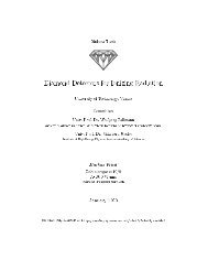
Tesis Doctoral<br />
Departament d’Enginyeria Electrònica<br />
Universitat Autònoma de Barcelona<br />
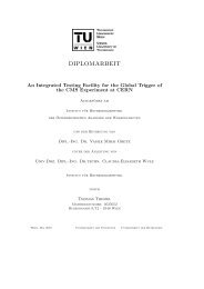
<strong>The</strong> <strong>CMS</strong> <strong>Trigger</strong> <strong>Supervisor</strong>:<br />
Control and Hardware Monitoring System of the <strong>CMS</strong><br />
Level-1 <strong>Trigger</strong> at CERN<br />
Ildefons Magrans de Abril<br />
Directora:<br />
Dra. Claudia-Elisabeth Wulz<br />
Tutora:<br />
Dra. Montserrat Nafría Maqueda<br />
March 2008
Dr. Claudia-Elisabeth Wulz, <strong>CMS</strong>-<strong>Trigger</strong> Group leader of the Institute for High Energy Physics in Vienna, and<br />
Deputy <strong>CMS</strong> <strong>Trigger</strong> Project Manager<br />
CERTIFIES<br />
That the dissertation <strong>The</strong> <strong>CMS</strong> <strong>Trigger</strong> <strong>Supervisor</strong>: Control and Hardware Monitoring System of the <strong>CMS</strong> Level-<br />
1 <strong>Trigger</strong> at CERN, presented by Ildefons Magrans de Abril to fulfil the degree of Doctor en Enginyeria<br />
Electrònica, has been performed under her supervision.<br />
Bellaterra, March de 2008.<br />
Dra. Claudia-Elisabeth Wulz
Abstract<br />
<strong>The</strong> experiments <strong>CMS</strong> (Compact Muon Solenoid) and ATLAS (A Toroidal LHC ApparatuS) at the Large<br />
Hadron Collider (LHC) are the greatest exponents of the rising complexity in High Energy Physics (HEP) data<br />
handling instrumentation. Tens of millions of readout channels, tens of thousands of hardware boards and the<br />
same order of connections are figures of merit. However, the hardware volume is not the only complexity<br />
dimension, the unprecedented large number of research institutes and scientists that form the international<br />
collaborations, and the long design, development, commissioning and operational phases are additional factors<br />
that must be taken into account.<br />
<strong>The</strong> Level-1 (L1) trigger decision loop is an excellent example of these difficulties. This system is based on a<br />
pipelined logic destined to analyze without deadtime the data from each LHC bunch crossing occurring every<br />
25_ns, using special coarsely segmented trigger data from the detectors. <strong>The</strong> L1 trigger is responsible for<br />
reducing the rate of accepted crossings to below 100 kHz. While the L1 trigger is taking its decision the full<br />
high-precision data of all detector channels are stored in the detector front-end buffers, which are only read out if<br />
the event is accepted. <strong>The</strong> Level-1 Accept (L1A) decision is communicated to the sub-detectors through the<br />
Timing, <strong>Trigger</strong> and Control (TTC) system. <strong>The</strong> L1 decision loop hardware system was built by more than ten<br />
research institutes with a development and construction period of nearly ten years, featuring more than fifty<br />
VME crates, and thousands of boards and connections.<br />
In this context, it is mandatory to provide software tools that ease integration and the short, medium and long<br />
term operation of the experiment. This research work proposes solutions, based on web services technologies, to<br />
simplify the implementation and operation of software control systems to manage hardware devices for HEP<br />
experiments. <strong>The</strong> main contribution of this work is the design and development of a hardware management<br />
system intended to enable the operation and integration of the L1 decision loop of the <strong>CMS</strong> experiment (<strong>CMS</strong><br />
<strong>Trigger</strong> <strong>Supervisor</strong>, TS).<br />
<strong>The</strong> TS conceptual design proposes a hierarchical distributed system which fits the web services based model of<br />
the <strong>CMS</strong> Online SoftWare Infrastructure (OSWI) well. <strong>The</strong> functional scope of this system covers the<br />
configuration, testing and monitoring of the L1 decision loop hardware, and its interaction with the overall <strong>CMS</strong><br />
experiment control system and the rest of the experiment. Together with the technical design aspects, the project<br />
organization strategy is discussed.<br />
<strong>The</strong> main topic follows an initial investigation about the usage of the eXtended Markup Language (XML) as<br />
uniform data representation format for a software environment to implement hardware management systems for<br />
HEP experiments. This model extends the usage of XML beyond the boundaries of the control and monitoring<br />
related data and proposes its usage also for the code. This effort, carried out in the context of the <strong>CMS</strong> <strong>Trigger</strong><br />
and Data Acquisition project, improved the overall team knowledge on XML technologies, created a pool of<br />
ideas and helped to anticipate the main TS requirements and architectural concepts.<br />
i
Visual summary<br />
<strong>The</strong> following diagram presents a visual summary of the PhD thesis. It consists of text boxes summarizing the<br />
main ideas and labeled arrows connecting them. <strong>The</strong> author’s contribution to peer reviewed journals (p),<br />
international conferences (c) and supervised master theses (t) are also indicated next to each text box.<br />
Motivation<br />
Chapter 1<br />
Unprecedented complexity related to the implementation of hardware control system for the<br />
last generation of high energy physics experiments. Very large hardware systems, human<br />
collaborations, and design, development and operational periods.<br />
Chapter 2<br />
Chapters 1, 3<br />
Generic solution<br />
[39]p<br />
Development model: [50]p<br />
•XML for data and code.<br />
•Interpreted code.<br />
First lessons<br />
Concrete case and main thesis goal<br />
Control and monitoring system for the<br />
Level-1 (L1) trigger decision loop.<br />
Chapter 2<br />
Chapter 3<br />
•Web services and XDAQ middleware as<br />
suitable technologies.<br />
•Experience of developing a hardware<br />
management system for the <strong>CMS</strong> experiment.<br />
Experience<br />
Requirements<br />
[56]p<br />
Conceptual design of control system for the <strong>CMS</strong> L1 decision loop (<strong>Trigger</strong> <strong>Supervisor</strong>, TS): [60]c<br />
•Requirements.<br />
•Project organization.<br />
•Layered design: Framework, System, Services.<br />
Chapter 4<br />
Framework design<br />
•Baseline technology survey.<br />
•Additional developments.<br />
[89]c<br />
[90]t<br />
•Performance measurements.<br />
System design<br />
Chapter 5<br />
•Design guidelines.<br />
•Distributed software system architecture.<br />
[95]c<br />
Services design<br />
Chapter 6<br />
Chapters 7, 8<br />
<strong>The</strong>sis achievements<br />
•Configuration, interconnection test<br />
and GUI services.<br />
•New software environment model: confirms XML and XDAQ.<br />
•TS design and project organization as a successful experience for future experiments.<br />
•A building block of the <strong>CMS</strong> experiment.<br />
•A contribution to the <strong>CMS</strong> operation.<br />
•Proposal for a uniform <strong>CMS</strong> experiment control system.<br />
[97]t<br />
ii
Contents<br />
ABSTRACT............................................................................................................................................................I<br />
VISUAL SUMMARY............................................................................................................................................... II<br />
CONTENTS.........................................................................................................................................................III<br />
ACRONYMS..................................................................................................................................................... VII<br />
CHAPTER 1 INTRODUCTION..................................................................................................................... 1<br />
1.1 CERN AND THE LARGE HADRON COLLIDER ........................................................................................... 1<br />
1.2 THE COMPACT MUON SOLENOID DETECTOR ........................................................................................... 3<br />
1.3 THE TRIGGER AND DAQ SYSTEM ............................................................................................................ 5<br />
1.3.1 Overview ......................................................................................................................................... 5<br />
1.3.2 <strong>The</strong> Level-1 trigger decision loop ................................................................................................... 5<br />
1.3.2.1 Calorimeter <strong>Trigger</strong>..................................................................................................................................... 6<br />
1.3.2.2 Muon <strong>Trigger</strong> .............................................................................................................................................. 7<br />
1.3.2.3 Global <strong>Trigger</strong> ............................................................................................................................................. 7<br />
1.3.2.4 Timing <strong>Trigger</strong> and Control System............................................................................................................ 7<br />
1.4 THE <strong>CMS</strong> EXPERIMENT CONTROL SYSTEM ............................................................................................. 8<br />
1.4.1 Run Control and monitoring System ...............................................................................................8<br />
1.4.2 Detector Control System ................................................................................................................. 9<br />
1.4.3 Cross-platform DAQ framework..................................................................................................... 9<br />
1.4.4 Sub-system Online Software Infrastructure................................................................................... 10<br />
1.4.5 Architecture................................................................................................................................... 10<br />
1.5 RESEARCH PROGRAM............................................................................................................................. 11<br />
1.5.1 Motivation ..................................................................................................................................... 11<br />
1.5.2 Goals ............................................................................................................................................. 12<br />
CHAPTER 2 UNIFORM MANAGEMENT OF DATA ACQUISITION DEVICES WITH XML ........ 13<br />
2.1 INTRODUCTION ...................................................................................................................................... 13<br />
2.2 KEY REQUIREMENTS .............................................................................................................................. 13<br />
2.3 A UNIFORM APPROACH FOR HARDWARE CONFIGURATION CONTROL AND TESTING ................................ 14<br />
2.3.1 XML as a uniform syntax .............................................................................................................. 14<br />
2.3.2 XML based control language ........................................................................................................ 15<br />
2.4 INTERPRETER DESIGN............................................................................................................................. 17<br />
2.4.1 Polymorphic structure................................................................................................................... 17<br />
2.5 USE IN A DISTRIBUTED ENVIRONMENT ................................................................................................... 18<br />
2.6 HARDWARE MANAGEMENT SYSTEM PROTOTYPE ................................................................................... 18<br />
2.7 PERFORMANCE COMPARISON................................................................................................................. 20<br />
2.8 PROTOTYPE STATUS............................................................................................................................... 20<br />
CHAPTER 3 TRIGGER SUPERVISOR CONCEPT................................................................................. 21<br />
3.1 INTRODUCTION ...................................................................................................................................... 21<br />
3.2 REQUIREMENTS ..................................................................................................................................... 22<br />
iii
3.2.1 Functional requirements ............................................................................................................... 22<br />
3.2.2 Non-functional requirements......................................................................................................... 23<br />
3.3 DESIGN .................................................................................................................................................. 25<br />
3.3.1 Initial discussion on technology.................................................................................................... 25<br />
3.3.2 Cell................................................................................................................................................ 26<br />
3.3.3 <strong>Trigger</strong> <strong>Supervisor</strong> services .......................................................................................................... 27<br />
3.3.3.1 Configuration............................................................................................................................................. 27<br />
3.3.3.2 Reconfiguration......................................................................................................................................... 29<br />
3.3.3.3 Testing....................................................................................................................................................... 29<br />
3.3.3.4 Monitoring................................................................................................................................................. 31<br />
3.3.3.5 Start-up...................................................................................................................................................... 31<br />
3.3.4 Graphical User Interface .............................................................................................................. 32<br />
3.3.5 Configuration and conditions database ........................................................................................ 32<br />
3.4 PROJECT COMMUNICATION CHANNELS .................................................................................................. 32<br />
3.5 PROJECT DEVELOPMENT ........................................................................................................................ 33<br />
3.6 TASKS AND RESPONSIBILITIES................................................................................................................ 34<br />
3.7 CONCEPTUAL DESIGN IN PERSPECTIVE................................................................................................... 35<br />
CHAPTER 4 TRIGGER SUPERVISOR FRAMEWORK......................................................................... 37<br />
4.1 CHOICE OF AN ADEQUATE FRAMEWORK ................................................................................................ 37<br />
4.2 REQUIREMENTS ..................................................................................................................................... 38<br />
4.2.1 Requirements covered by XDAQ................................................................................................... 38<br />
4.2.2 Requirements non-covered by XDAQ............................................................................................ 38<br />
4.3 CELL FUNCTIONAL STRUCTURE.............................................................................................................. 39<br />
4.3.1 Cell Operation............................................................................................................................... 39<br />
4.3.2 Cell command................................................................................................................................ 41<br />
4.3.3 Factories and plug-ins .................................................................................................................. 41<br />
4.3.4 Pools.............................................................................................................................................. 41<br />
4.3.5 Controller interface....................................................................................................................... 41<br />
4.3.6 Response control module .............................................................................................................. 42<br />
4.3.7 Access control module................................................................................................................... 42<br />
4.3.8 Shared resource manager ............................................................................................................. 42<br />
4.3.9 Error manager .............................................................................................................................. 42<br />
4.3.10 Xhannel ......................................................................................................................................... 42<br />
4.3.11 Monitoring facilities...................................................................................................................... 43<br />
4.4 IMPLEMENTATION.................................................................................................................................. 43<br />
4.4.1 Layered architecture ..................................................................................................................... 43<br />
4.4.2 External packages ......................................................................................................................... 43<br />
4.4.2.1 Log4cplus.................................................................................................................................................. 43<br />
4.4.2.2 Xerces........................................................................................................................................................ 44<br />
4.4.2.3 Graphviz.................................................................................................................................................... 44<br />
4.4.2.4 ChartDirector............................................................................................................................................. 44<br />
4.4.2.5 Dojo........................................................................................................................................................... 44<br />
4.4.2.6 Cgicc ......................................................................................................................................................... 45<br />
4.4.2.7 Logging collector....................................................................................................................................... 45<br />
4.4.3 XDAQ development....................................................................................................................... 45<br />
4.4.4 <strong>Trigger</strong> <strong>Supervisor</strong> framework ...................................................................................................... 46<br />
4.4.4.1 <strong>The</strong> cell...................................................................................................................................................... 47<br />
4.4.4.2 Cell command............................................................................................................................................ 48<br />
4.4.4.3 Cell operation ............................................................................................................................................ 49<br />
4.4.4.4 Factories, pools and plug-ins ..................................................................................................................... 50<br />
4.4.4.5 Controller interface.................................................................................................................................... 51<br />
4.4.4.6 Response control module........................................................................................................................... 51<br />
4.4.4.7 Access control module............................................................................................................................... 53<br />
4.4.4.8 Error management module ........................................................................................................................ 53<br />
4.4.4.9 Xhannel ..................................................................................................................................................... 53<br />
4.4.4.9.1 CellXhannelCell .................................................................................................................................. 54<br />
4.4.4.9.2 CellXhannelTb .................................................................................................................................... 55<br />
iv
4.4.4.10 CellToolbox .......................................................................................................................................... 56<br />
4.4.4.11 Graphical User Interface ....................................................................................................................... 56<br />
4.4.4.12 Monitoring infrastructure ...................................................................................................................... 57<br />
4.4.4.12.1 Model ................................................................................................................................................ 58<br />
4.4.4.12.2 Declaration and definition of monitoring items ................................................................................. 58<br />
4.4.4.13 Logging infrastructure........................................................................................................................... 61<br />
4.4.4.14 Start-up infrastructure ........................................................................................................................... 62<br />
4.5 CELL DEVELOPMENT MODEL.................................................................................................................. 62<br />
4.6 PERFORMANCE AND SCALABILITY MEASUREMENTS............................................................................... 63<br />
4.6.1 Test setup....................................................................................................................................... 63<br />
4.6.2 Command execution ...................................................................................................................... 63<br />
4.6.3 Operation instance initialization................................................................................................... 65<br />
4.6.4 Operation state transition ............................................................................................................. 66<br />
CHAPTER 5 TRIGGER SUPERVISOR SYSTEM.................................................................................... 69<br />
5.1 INTRODUCTION ...................................................................................................................................... 69<br />
5.2 DESIGN GUIDELINES............................................................................................................................... 69<br />
5.2.1 Homogeneous underlying infrastructure....................................................................................... 69<br />
5.2.2 Hierarchical control system architecture...................................................................................... 69<br />
5.2.3 Centralized monitoring, logging and start-up systems architecture ............................................. 70<br />
5.2.4 Persistency infrastructure ............................................................................................................. 70<br />
5.2.4.1 Centralized access ..................................................................................................................................... 70<br />
5.2.4.2 Common monitoring and logging databases.............................................................................................. 70<br />
5.2.4.3 Centralized maintenance............................................................................................................................ 70<br />
5.2.5 Always on system........................................................................................................................... 70<br />
5.3 SUB-SYSTEM INTEGRATION.................................................................................................................... 71<br />
5.3.1 Building blocks.............................................................................................................................. 71<br />
5.3.1.1 <strong>The</strong> TS node .............................................................................................................................................. 71<br />
5.3.1.2 Common services ...................................................................................................................................... 72<br />
5.3.1.2.1 Logging collector................................................................................................................................ 72<br />
5.3.1.2.2 Tstore................................................................................................................................................... 72<br />
5.3.1.2.3 Monitor collector ................................................................................................................................. 72<br />
5.3.1.2.4 Mstore.................................................................................................................................................. 73<br />
5.3.2 Integration..................................................................................................................................... 73<br />
5.3.2.1 Integration parameters ............................................................................................................................... 73<br />
5.3.2.1.1 OSWI parameters ................................................................................................................................ 73<br />
5.3.2.1.2 Hardware setup parameters.................................................................................................................. 74<br />
5.3.2.2 Integration cases ........................................................................................................................................ 74<br />
5.3.2.2.1 Cathode Strip Chamber Track Finder.................................................................................................. 74<br />
5.3.2.2.2 Global <strong>Trigger</strong> and Global Muon <strong>Trigger</strong>............................................................................................ 74<br />
5.3.2.2.3 Drift Tube Track Finder....................................................................................................................... 75<br />
5.3.2.2.4 Resistive Plate Chamber...................................................................................................................... 76<br />
5.3.2.2.5 Global Calorimeter <strong>Trigger</strong> ................................................................................................................. 76<br />
5.3.2.2.6 Hadronic Calorimeter .......................................................................................................................... 77<br />
5.3.2.2.7 <strong>Trigger</strong>, Timing and Control System................................................................................................... 78<br />
5.3.2.2.8 Luminosity Monitoring System........................................................................................................... 79<br />
5.3.2.2.9 Central cell .......................................................................................................................................... 80<br />
5.3.2.3 Integration summary.................................................................................................................................. 80<br />
5.4 SYSTEM INTEGRATION ........................................................................................................................... 81<br />
5.4.1 Control system............................................................................................................................... 81<br />
5.4.2 Monitoring system......................................................................................................................... 82<br />
5.4.3 Logging system.............................................................................................................................. 83<br />
5.4.4 Start-up system.............................................................................................................................. 83<br />
5.5 SERVICES DEVELOPMENT PROCESS ........................................................................................................ 83<br />
CHAPTER 6 TRIGGER SUPERVISOR SERVICES ................................................................................ 87<br />
6.1 INTRODUCTION ...................................................................................................................................... 87<br />
6.2 CONFIGURATION.................................................................................................................................... 87<br />
6.2.1 Description.................................................................................................................................... 87<br />
v
6.2.2 Implementation.............................................................................................................................. 88<br />
6.2.2.1 Central cell ................................................................................................................................................ 89<br />
6.2.2.2 <strong>Trigger</strong> sub-systems................................................................................................................................... 92<br />
6.2.2.3 Global <strong>Trigger</strong> ........................................................................................................................................... 93<br />
6.2.2.3.1 Command interface.............................................................................................................................. 94<br />
6.2.2.3.2 Configuration operation and database ............................................................................................... 101<br />
6.2.2.4 Sub-detector cells .................................................................................................................................... 103<br />
6.2.2.5 Luminosity monitoring system................................................................................................................ 103<br />
6.2.3 Integration with the Run Control and Monitoring System .......................................................... 103<br />
6.3 INTERCONNECTION TEST...................................................................................................................... 105<br />
6.3.1 Description.................................................................................................................................. 105<br />
6.3.2 Implementation............................................................................................................................ 105<br />
6.3.2.1 Central cell .............................................................................................................................................. 105<br />
6.3.2.2 Sub-system cells ...................................................................................................................................... 107<br />
6.4 MONITORING ....................................................................................................................................... 108<br />
6.4.1 Description.................................................................................................................................. 108<br />
6.5 GRAPHICAL USER INTERFACES............................................................................................................. 109<br />
6.5.1 Global <strong>Trigger</strong> control panel ...................................................................................................... 109<br />
CHAPTER 7 HOMOGENEOUS SUPERVISOR AND CONTROL SOFTWARE INFRASTRUCTURE<br />
FOR THE <strong>CMS</strong> EXPERIMENT AT SLHC................................................................................................... 111<br />
7.1 INTRODUCTION .................................................................................................................................... 111<br />
7.2 TECHNOLOGY BASELINE ...................................................................................................................... 111<br />
7.3 ROAD MAP ........................................................................................................................................... 112<br />
7.4 SCHEDULE AND RESOURCE ESTIMATES ................................................................................................ 113<br />
CHAPTER 8 SUMMARY AND CONCLUSIONS.................................................................................... 115<br />
8.1 CONTRIBUTIONS TO THE <strong>CMS</strong> GENETIC BASE...................................................................................... 116<br />
8.1.1 XSEQ........................................................................................................................................... 116<br />
8.1.2 <strong>Trigger</strong> <strong>Supervisor</strong> ...................................................................................................................... 117<br />
8.1.3 <strong>Trigger</strong> <strong>Supervisor</strong> framework ....................................................................................................117<br />
8.1.4 <strong>Trigger</strong> <strong>Supervisor</strong> system........................................................................................................... 118<br />
8.1.5 <strong>Trigger</strong> <strong>Supervisor</strong> services ........................................................................................................ 118<br />
8.1.6 <strong>Trigger</strong> <strong>Supervisor</strong> Continuation ................................................................................................ 119<br />
8.2 CONTRIBUTION TO THE <strong>CMS</strong> BODY ..................................................................................................... 119<br />
8.3 FINAL REMARKS................................................................................................................................... 119<br />
APPENDIX A TRIGGER SUPERVISOR SOAP API............................................................................ 121<br />
A.1 INTRODUCTION .................................................................................................................................... 121<br />
A.2 REQUIREMENTS ................................................................................................................................... 121<br />
A.3 SOAP API ........................................................................................................................................... 121<br />
A.3.1 Protocol....................................................................................................................................... 121<br />
A.3.2 Request message.......................................................................................................................... 123<br />
A.3.3 Reply message ............................................................................................................................. 124<br />
A.3.4 Cell command remote API .......................................................................................................... 125<br />
A.3.5 Cell Operation remote API ......................................................................................................... 125<br />
A.3.5.1 OpInit ...................................................................................................................................................... 125<br />
A.3.5.2 OpSendCommand.................................................................................................................................... 126<br />
A.3.5.3 OpReset ................................................................................................................................................... 127<br />
A.3.5.4 OpGetState .............................................................................................................................................. 128<br />
A.3.5.5 OpKill...................................................................................................................................................... 129<br />
ACKNOWLEDGEMENTS.............................................................................................................................. 131<br />
REFERENCES.................................................................................................................................................. 133<br />
vi
Acronyms<br />
ACM<br />
AJAX<br />
ALICE<br />
API<br />
ATLAS<br />
aTTS<br />
BX<br />
BU<br />
CCC<br />
CCI<br />
CERN<br />
CGI<br />
CKC<br />
<strong>CMS</strong><br />
CSC<br />
CSCTF<br />
CVS<br />
DAQ<br />
DCC<br />
DCS<br />
DB<br />
DBWG<br />
DIM<br />
DOM<br />
DT<br />
DTSC<br />
DTTF<br />
ECAL<br />
ECS<br />
ERM<br />
EVM<br />
FDL<br />
Access Control Module<br />
Asynchronous JavaScript and XML<br />
A Large Ion Collider Experiment<br />
Application Program Interface<br />
A Toroidal LHC Apparatus<br />
Asynchronous <strong>Trigger</strong> Throttle System<br />
Bunch crossing<br />
Builder Unit<br />
Central Crate Cell<br />
Control Cell Interface<br />
Conseil Europeen pour la Recherche Nucleaire<br />
Common Gateway Interface<br />
ClocK crate cell<br />
Compact Muon Solenoid<br />
Cathode Strip Chamber<br />
Cathode Strip Chamber Track Finder<br />
Concurrent Versions System<br />
Data Acquisition<br />
DTTF Central Cell<br />
Detector Control System<br />
DataBase<br />
<strong>CMS</strong> DataBase Working Group<br />
Distributed Information Management System<br />
Document Object Model<br />
Drift Tube<br />
Drift Tube Sector Collector<br />
Drift Tube Track Finder<br />
Electromagnetic CALorimeter<br />
Experiment Control System<br />
Error Manager<br />
EVent Manager<br />
Final Decision Logic<br />
vii
FED<br />
FLFM<br />
FM<br />
FPGA<br />
FRL<br />
FSM<br />
FTE<br />
FU<br />
GCT<br />
GMT<br />
GT<br />
GTFE<br />
GTL<br />
GUI<br />
HAL<br />
HCAL<br />
HF<br />
HLT<br />
HTML<br />
HTTP<br />
HEP<br />
HW<br />
I2O<br />
JSP<br />
LEP<br />
LHC<br />
LHCb<br />
LMS<br />
LMSS<br />
LUT<br />
L1<br />
L1A<br />
ORCA<br />
OSWI<br />
PCI<br />
PSB<br />
PSI<br />
PVSS<br />
RC<br />
Front-end Device<br />
First Level Function Manager<br />
Function manager<br />
Field Programmable Gate Array<br />
Front-end Readout Link board<br />
Finite State Machine<br />
Full Time Equivalent<br />
Filter Unit<br />
Global Calorimeter <strong>Trigger</strong><br />
Global Muon <strong>Trigger</strong><br />
Global <strong>Trigger</strong><br />
Global <strong>Trigger</strong> Front-end<br />
Global <strong>Trigger</strong> Logic<br />
Graphical User Interface<br />
Hardware Access Library<br />
Hadronic CALorimeter<br />
Forward Hadronic calorimeter<br />
High Level <strong>Trigger</strong><br />
HyperText Markup Language<br />
HyperText Transfer Protocol<br />
High Energy Physics<br />
HardWare<br />
Intelligent Input/Output<br />
Java Server Pages<br />
Large Electron and Positron collider<br />
Large Hadron Collider<br />
Large Hadron Collider beauty experiment<br />
Luminosity Monitoring System<br />
Luminosity Monitoring Software System<br />
Look Up Table<br />
Level-1<br />
Level-1 Accept signal<br />
Object Oriented Reconstruction for <strong>CMS</strong> Analysis<br />
Online SoftWare Infrastructure<br />
Peripheral Component Interconnect bus standard<br />
Pipeline Synchronizing Buffer<br />
PVSS SOAP Interface<br />
ProzessVisualisierungs- und SteuerungSSystem<br />
Run Control<br />
viii
RCM<br />
R<strong>CMS</strong><br />
RCT<br />
RF2TTC<br />
RPC<br />
RU<br />
SRM<br />
SW<br />
SCADA<br />
SDRAM<br />
SEC<br />
SLHC<br />
SLOC<br />
SOAP<br />
SRM<br />
SSCS<br />
sTTS<br />
TCS<br />
TFC<br />
TIM<br />
TOTEM<br />
TPG<br />
TriDAS<br />
TS<br />
TSCS<br />
TSMS<br />
TSLS<br />
TSM<br />
TSSS<br />
TTC<br />
TTCci<br />
TTCrx<br />
TTS<br />
UA1<br />
UDP<br />
UML<br />
URL<br />
VME<br />
WSDL<br />
Response Control Module<br />
Run Control and Monitoring System<br />
Regional Calorimeter <strong>Trigger</strong><br />
TTC machine interface<br />
Resistive Plate Chamber and Remote Process Call<br />
Readout Unit<br />
Shared Resources Manager<br />
SoftWare<br />
<strong>Supervisor</strong>y Controls And Data Acquisition<br />
Synchronous Dynamic Random Access Memory<br />
Service Entry Cell<br />
Super LHC<br />
Source Lines Of Code<br />
Simple Object Access Protocol<br />
Shared Resource Module<br />
Sub-detectors <strong>Supervisor</strong>y and Control Systems<br />
Synchronous <strong>Trigger</strong> Throttle System<br />
<strong>Trigger</strong> Control System<br />
Track Finder Cell<br />
TIMing module<br />
TOTal cross cection, Elastic scattering and diffraction dissociation at the LHC<br />
<strong>Trigger</strong> Primitive Generator (HF, HCAL, ECAL, RPC, CSC and DT)<br />
<strong>Trigger</strong> and Data Acquisition System<br />
<strong>Trigger</strong> <strong>Supervisor</strong><br />
<strong>Trigger</strong> <strong>Supervisor</strong> Control System<br />
<strong>Trigger</strong> <strong>Supervisor</strong> Monitoring System<br />
<strong>Trigger</strong> <strong>Supervisor</strong> Logging System<br />
Task Scheduler Module<br />
<strong>Trigger</strong> <strong>Supervisor</strong> Start-up System<br />
Timing, <strong>Trigger</strong> and Control System<br />
<strong>CMS</strong> version of the TTC VME interface module<br />
A Timing, <strong>Trigger</strong> and Control Receiver ASIC for LHC Detectors<br />
<strong>Trigger</strong> Throttle System<br />
Underground Area 1 experiment<br />
User Datagram Protocol<br />
Unified Modeling Language<br />
Uniform Resource Locator<br />
Versa Module Europa bus standard<br />
Web Service Description Language<br />
ix
W3C<br />
XDAQ<br />
XML<br />
XPath<br />
XSD<br />
XSEQ<br />
World Wide Web Consortium<br />
Cross-platform DAQ framework<br />
EXtensible Markup Language<br />
XML Path language<br />
XML Schema Document<br />
Cross-platform SEQuencer<br />
x
Chapter 1<br />
Introduction<br />
1.1 CERN and the Large Hadron Collider<br />
At CERN, the European laboratory for particle physics, the fundamental structure of matter is studied using<br />
particle accelerators. <strong>The</strong> acronym CERN comes from the earlier French title: “Conseil Européen pour la<br />
Recherche Nucléaire”. CERN is located on the Franco-Swiss border west of Geneva. CERN was founded in<br />
1954, and is currently being funded by 20 European countries. CERN employs just under 3000 people, only a<br />
fraction of those are actually particle physicists. This reflects the role of CERN: it does not so much perform<br />
particle physics itself, but rather offers its research facilities to the particle physicists in Europe and increasingly<br />
in the whole world. About half of the world’s particle physicists, some 6500 researchers from over 500<br />
universities and institutes in some 80 countries, use CERN’s facilities.<br />
<strong>The</strong> latest of these facilities that has been designed and is being built at CERN is the Large Hadron Collider or<br />
LHC [1]. It is contained in a 26.7 km circumference tunnel located underground at a depth ranging from 50 to<br />
150 meters (Figure 1-1). <strong>The</strong> tunnel was formerly used for the Large Electron Positron (LEP) collider. <strong>The</strong> LHC<br />
project consists of a superconducting magnet system with two beam channels designed to bring two proton<br />
beams into collision, at a centre of mass energy of 14 TeV. It will also be able to provide collisions of heavy<br />
nuclei (Pb-Pb) produced at a centre of mass energy of 2.76 TeV per nucleon.<br />
When the two counter-rotating proton bunches cross, protons within bunches can collide producing new particles<br />
in inelastic interactions. Such inelastic interactions are also referred to as “events”. <strong>The</strong> probability for such<br />
inelastic collisions to take place is determined by the cross section for proton-proton interactions and by the<br />
density and frequency of the proton bunches. <strong>The</strong> related quantity, which is a characteristic of the collider, is<br />
called the luminosity. <strong>The</strong> design luminosity of the LHC is 10 34 cm −2 s −1 . <strong>The</strong> proton-proton inelastic cross<br />
section σ inel depends on the proton’s energy. At the LHC center-of-mass energy of 14 TeV, σ inel is expected to be<br />
70 mb (70·10 −27 cm 2 ). <strong>The</strong>refore, the number of inelastic interactions per second (event rate), is the product of the<br />
cross section (σ inel ) and the luminosity (L): N inel = σ·L = 7·10 8 s -1 . As the bunch crossing rate is 40 MHz and<br />
bearing in mind that during normal operation at the LHC not all bunches are filled (only 2808 out of 3564), the<br />
average number of events per bunch crossing can be calculated as 7·10 8·25·10 −9·3564/2808 ≈ 22.<br />
<strong>The</strong> main LHC functional parameters that are most important from the experimental point of view are reported in<br />
Table 1-1. At the energy scale and raw data rate aimed at LHC, the design of the detectors faces a number of new<br />
implementation challenges. LHC detectors must have the capability of isolating and reconstructing the<br />
interesting events as only few events can be recorded out of the 40 million each second. Another technical<br />
challenge is the extremely hostile radiation environment.
Introduction 2<br />
Figure 1-1: Schematic illustration of the LHC ring with the four experimental points.<br />
Design Luminosity (L)<br />
Bunch crossing (BX) rate<br />
10 34 cm −2 s −1<br />
40 MHz<br />
Number of bunches per orbit 3564<br />
Number of filled bunches per orbit 2808<br />
Average number of events per bunch crossing 22<br />
Table 1-1: Main LHC functional parameters that are most important from the experimental point of view.<br />
<strong>The</strong>re are four collision points spread over the LHC ring which house the main LHC experiments. <strong>The</strong> two<br />
largest, Compact Muon Solenoid (<strong>CMS</strong>, [2]) and A Toroidal LHC ApparatuS (ATLAS, [3]) are general purpose<br />
experiments that take different approaches, in particular to the detection of muons.<br />
<strong>CMS</strong> is built around a very high field solenoid magnet; its relative compactness derives from the fact that there is<br />
a massive iron yoke so that the muons are detected by their bending over a relatively short distance in a very high<br />
magnetic field. <strong>The</strong> ATLAS experiment is substantially bigger and essentially relies upon an air-cored toroidal<br />
magnet system for the measurement of the muons.<br />
Two more special-purpose experiments have been approved to start their operation at the switch on of the LHC<br />
machine, A Large Ion Collider Experiment (ALICE, [4]) and the Large Hadron Collider beauty experiment<br />
(LHC-b, [5]). ALICE is a dedicated heavy-ion detector that will exploit the unique physics potential of nucleusnucleus<br />
interactions at LHC energies, and the LHC-b detector is dedicated to the study of CP violation and other<br />
rare phenomena in the decays of beauty particles.
<strong>The</strong> Compact Muon Solenoid detector 3<br />
1.2 <strong>The</strong> Compact Muon Solenoid detector<br />
<strong>The</strong> <strong>CMS</strong> detector is a general-purpose quasi-hermetic detector. This kind of particle detector is designed to<br />
observe all possible decay products of an interaction between subatomic particles in a collider by covering as<br />
large an area around the interaction point as possible and incorporating multiple types of sub-detectors. <strong>CMS</strong> is<br />
called “hermetic” because it is designed to let as few particles as possible escape.<br />
<strong>The</strong>re are three main components of a particle physics collider detector. From the inside out, the first is a tracker,<br />
which measures the momenta of charged particles as they curve in a magnetic field. Next there are calorimeters,<br />
which measure the energy of most charged and neutral particles by absorbing them in dense material, and a<br />
muon system which measures the type of particle that is not stopped in the calorimeters and can still be detected.<br />
<strong>The</strong> concept of the <strong>CMS</strong> detector was based on the requirements of having a very good muon system whilst<br />
keeping the detector dimensions compact. In this case, only a strong magnetic field would guarantee good<br />
momentum resolution for high momentum muons. Studies showed that the required magnetic field could be<br />
generated by a superconducting solenoid. It is also a particularity of <strong>CMS</strong> that the solenoid surrounds the<br />
calorimeter detectors.<br />
Figure 1-2 shows a schematic drawing of the <strong>CMS</strong> detector and its components that will be described in detail in<br />
the subsequent sections. Figure 1-3 shows a transverse slice of the detector. Trajectories of different kinds of<br />
particles and the traces they leave in the different components of the detector are also shown.<br />
<strong>The</strong> coordinate system adopted by <strong>CMS</strong> has the origin centered at the nominal collision point inside the<br />
experiment, the y-axis pointing vertically upward, and the x-axis pointing radially inward toward the center of<br />
the LHC. Thus, the z-axis points along the beam direction toward the Jura mountains from LHC Point 5. <strong>The</strong><br />
azimuthal angle (φ) is measured from the x-axis in the x-y plane. <strong>The</strong> polar angle (θ) is measured from the z-axis.<br />
Pseudorapidity is defined as η = -ln tan(θ/2). Thus, the momentum and energy measured transverse to the beam<br />
direction, denoted by p T and E T , respectively, are computed from the x and y components.<br />
Figure 1-2: Drawing of the complete <strong>CMS</strong> detector, showing both the scale and complexity.
Introduction 4<br />
Figure 1-3: Slice through <strong>CMS</strong> showing particles incident on the different sub-detectors.<br />
Tracker<br />
<strong>The</strong> tracking system [6] records the helix traced by a charged particle that curves in a magnetic field by<br />
localizing it in space in finely-segmented layers of detecting material composed of silicon. <strong>The</strong> degree to which<br />
the particle curves is inversely proportional to its momentum perpendicular to the beam, while the degree to<br />
which it drifts in the direction of the beam axis gives its momentum in that direction.<br />
Calorimeters<br />
<strong>The</strong> calorimeter system is installed inside the coil. It slows particles down and absorbs their energy allowing that<br />
energy to be measured. This detector is divided into two types: the Electromagnetic Calorimeter (ECAL, [7]),<br />
made of lead tungstate (PbWO 4 ) crystals, absorbs particles that interact electromagnetically by producing<br />
electron/positron pairs and bremsstrahlung 1 ; and the Hadronic Calorimeter (HCAL, [8]), made of interleaved<br />
copper absorber and plastic scintillator plates, can detect hadrons which interact via the strong nuclear force.<br />
Muon system<br />
Of all the known stable particles, only muons and neutrinos pass through the calorimeter without losing most or<br />
all of their energy. Neutrinos are undetectable, and their existence must be inferred, but muons (which are<br />
charged) can be measured by an additional tracking system outside the calorimeters.<br />
A redundant and precise muon system was one of the first requirements of <strong>CMS</strong> [9]. <strong>The</strong> ability to trigger on and<br />
reconstruct muons, being an unmistakable signature for a large number of new physics processes <strong>CMS</strong> is<br />
designed to explore, is central to the concept. <strong>The</strong> muon system consists of three technologically different<br />
components: Resistive Plate Chambers (RPC), Drift Tubes (DT) and Cathode Strip Chambers (CSC).<br />
1 Bremsstrahlung is electromagnetic radiation produced by the deceleration of a charged particle, such as an electron, when<br />
deflected by another charged particle, such as an atomic nucleus.
<strong>The</strong> <strong>Trigger</strong> and DAQ system 5<br />
<strong>The</strong> muon system of <strong>CMS</strong> is embedded in the iron return yoke of the magnet. It makes use of the bending of<br />
muons in the magnetic field for transverse momentum measurements of muon tracks identified in association<br />
with the tracker. <strong>The</strong> large thickness of absorber material in the return yoke helps to filter out hadrons, so that<br />
muons are practically the only particles apart from neutrinos able to escape from the calorimeter system. <strong>The</strong><br />
muon system consists of 4 stations of muon chambers in the barrel region (Figure 1-3 shows how the 4 stations<br />
correspond to 4 layers of muon chambers) and disks in the forward region.<br />
1.3 <strong>The</strong> <strong>Trigger</strong> and DAQ system<br />
1.3.1 Overview<br />
<strong>The</strong> <strong>CMS</strong> <strong>Trigger</strong> and Data Acquisition (DAQ) system is designed to collect and to analyze the detector<br />
information at the LHC bunch crossing frequency of 40 MHz. <strong>The</strong> rate of events to be recorded for offline<br />
processing and analysis is of the order of 100 Hz. At the design luminosity of 10 34 cm −2 s −1 , the LHC rate of<br />
proton collisions will be around 22 per bunch crossing, producing approximately 1 MB of zero-suppressed data 2<br />
in the <strong>CMS</strong> readout system. <strong>The</strong> Level-1 (L1) trigger is designed to reduce the incoming data rate to a maximum<br />
of 100 kHz, by processing fast trigger information coming from the calorimeters and the muon chambers, and<br />
selecting events with interesting signatures. <strong>The</strong>refore, the DAQ system must sustain a maximum input rate of<br />
100 kHz, for an average data flow of 100 GB/s coming from about 650 data sources, and must provide enough<br />
computing power for a high level software trigger (HLT) to reduce the rate of stored events by a factor of 1000.<br />
In <strong>CMS</strong> all events that pass the Level-1 trigger are sent to a computer farm (Event Filter) that performs physics<br />
selections, using the offline reconstruction software, to filter events and achieve the required output rate. <strong>The</strong><br />
design of the <strong>CMS</strong> Data Acquisition system and of the High Level trigger is described in detail in the Technical<br />
Design Report [10]. <strong>The</strong> architecture of the <strong>CMS</strong> <strong>Trigger</strong> and DAQ system is shown schematically in Figure 1-4.<br />
Figure 1-4: Overview of the <strong>CMS</strong> <strong>Trigger</strong> and DAQ system architecture.<br />
1.3.2 <strong>The</strong> Level-1 trigger decision loop<br />
<strong>The</strong> L1 trigger [11] is a custom pipelined hardware logic intended to analyze the bunch crossing data every 25 ns<br />
without deadtime using special coarsely segmented trigger data from the muon systems and the calorimeters. <strong>The</strong><br />
L1 trigger reduces the rate of crossings to below 100 kHz.<br />
<strong>The</strong> L1 trigger has local, regional and global components. At the bottom end, the Local <strong>Trigger</strong>s, also called<br />
<strong>Trigger</strong> Primitive Generators (TPG), are based on energy deposits in calorimeter trigger towers 3 and track<br />
2 Zero suppression consists of eliminating leading zeros. This encoding is performed by the on-detector readout electronics to<br />
reduce the data volume.<br />
3 Each trigger tower identifies a detector region with an approximate (η,φ)-coverage of 0.087 x 0.087 rad.
Introduction 6<br />
3.2 µs<br />
192 L1A’s (128 Algorithms + 64 Technical <strong>Trigger</strong>s)<br />
Global <strong>Trigger</strong><br />
DAQ<br />
DAQ<br />
Drift Tube<br />
Track finder<br />
Drift Tube Sector<br />
Collector<br />
Slink<br />
Back pressure<br />
(sTTS)<br />
Local Control<br />
Local trigger Local 0<br />
Control 31<br />
Global Muon <strong>Trigger</strong><br />
CSC Track<br />
Finder<br />
RPC<br />
<strong>Trigger</strong><br />
DT CSC RPC<br />
Muon Det. Front End<br />
L1A + TTC<br />
ECAL TPG<br />
Global Calorimeter<br />
<strong>Trigger</strong><br />
Regional Calorimeter<br />
<strong>Trigger</strong><br />
HCAL/HF TPG<br />
ECAL HCAL HF<br />
Calorimeters Front End<br />
Back pressure<br />
(aTTS + sTTS)<br />
Partition<br />
controller 0<br />
OR (192 L1A)<br />
L1A + TTC<br />
<strong>Trigger</strong> Control System<br />
Partition<br />
controller 7<br />
OR (192 L1A)<br />
Figure 1-5: <strong>The</strong> Level-1 trigger decision loop.<br />
segments or hit patterns in muon chambers, respectively. Regional <strong>Trigger</strong>s (or Local <strong>Trigger</strong>s) combine their<br />
information and use pattern logic to determine ranked and sorted trigger objects such as electron or muon<br />
candidates in limited spatial regions. <strong>The</strong> rank is determined as a function of energy or momentum and quality,<br />
which reflects the level of confidence attributed to the L1 trigger parameter measurements, based on detailed<br />
knowledge of the detectors and trigger electronics and on the amount of information available. <strong>The</strong> Global<br />
Calorimeter and Global Muon <strong>Trigger</strong>s determine the highest-rank calorimeter and muon objects across the<br />
entire experiment and transfer them to the Global <strong>Trigger</strong>, the top entity of the L1 trigger hierarchy.<br />
While the L1 trigger is taking its decision the full high-precision data of all detector channels are stored in analog<br />
or digital buffers, which are only read out if the event is accepted. <strong>The</strong> L1 decision loop takes 3.2 μs or 128<br />
bunch crossings which is the size of the front-end buffers. <strong>The</strong> Level-1 Accept (L1A) decision is communicated<br />
to the sub-detectors through the Timing, <strong>Trigger</strong> and Control (TTC) system. Figure 1-5 shows a diagram of the<br />
L1 decision loop.<br />
1.3.2.1 Calorimeter <strong>Trigger</strong><br />
<strong>The</strong> first step of the Calorimeter trigger pipeline is the TPGs. For triggering purposes the calorimeters are<br />
subdivided in trigger towers. <strong>The</strong> TPGs sum the transverse energies measured in ECAL crystals or HCAL<br />
readout towers to obtain the trigger tower E T and attach the correct bunch crossing number. <strong>The</strong> TPG electronics<br />
is integrated with the calorimeter readout. <strong>The</strong> TPGs are transmitted through high-speed serial links to the<br />
Regional Calorimeter <strong>Trigger</strong> (RCT, [12]), which determines candidates for electrons or photons, jets, isolated<br />
hadrons and calculates energy sums in calorimeter regions of 4 x 4 trigger towers. <strong>The</strong>se objects are forwarded to<br />
the Global Calorimeter <strong>Trigger</strong> (GCT, [13]) where the best four objects of each category are sent to the Global<br />
<strong>Trigger</strong>.
<strong>The</strong> <strong>Trigger</strong> and DAQ system 7<br />
1.3.2.2 Muon <strong>Trigger</strong><br />
All three components of the muon systems (DT, CSC and RPC) take part in the trigger. <strong>The</strong> barrel DT chambers<br />
provide local trigger information in the form of track segments in the φ-projection and hit patterns in the η-<br />
projection. <strong>The</strong> endcap CSCs deliver 3-dimensional track segments. All chamber types also identify the bunch<br />
crossing of the corresponding event. <strong>The</strong> Regional Muon <strong>Trigger</strong> joins segments to complete tracks and assigns<br />
physical parameters. It consists of the DT Sector Collector (DTSC, [14]), DT Track Finders (DTTF, [15]) and<br />
CSC Track Finders (CSCTF, [16]). In addition, the RPC trigger chambers, which have excellent timing<br />
resolution, deliver their own track candidates based on regional hit patterns. <strong>The</strong> Global Muon <strong>Trigger</strong> (GMT,<br />
[17]) then combines the information from the three sub-detectors, achieving an improved momentum resolution<br />
and efficiency compared to the stand-alone systems.<br />
1.3.2.3 Global <strong>Trigger</strong><br />
<strong>The</strong> Global <strong>Trigger</strong> (GT, [18]) takes the decision to accept an event for further evaluation by the HLT based on<br />
trigger objects delivered by the GCT and GMT. <strong>The</strong> GT has five basic stages: input, logic, decision, distribution<br />
and readout. Three Pipeline Synchronizing Buffer (PSB) input boards receive the calorimeter trigger objects<br />
from the GCT and align them in time. <strong>The</strong> muons are received from the GMT through the backplane. An<br />
additional PSB board can receive direct trigger signals from sub-detectors or the TOTEM experiment [19] for<br />
special purposes such as calibration. <strong>The</strong>se signals are called “technical triggers”. <strong>The</strong> core of the GT is the<br />
Global <strong>Trigger</strong> Logic (GTL) board, in which algorithm calculations are performed. <strong>The</strong> most basic algorithms<br />
consist of applying p T or E T thresholds to single objects, or of requiring the jet multiplicities to exceed defined<br />
values. Since location and quality information is available, more complex algorithms based on topological<br />
conditions can also be programmed into the logic. <strong>The</strong> number of algorithms that can be executed in parallel is<br />
128, and up to 64 technical trigger bits may in addition be received directly from a dedicated PSB board. <strong>The</strong> set<br />
of algorithm calculations performed in parallel is called “trigger menu”.<br />
<strong>The</strong> results of the algorithm calculations are sent to the Final Decision Logic (FDL) board in the form of one bit<br />
per algorithm. Up to eight final ORs can be applied and correspondingly eight L1A signals can be issued. For<br />
normal physics data taking a single trigger mask is applied, and the L1A decision is taken accordingly. <strong>The</strong> rest<br />
of L1As are used for commissioning, calibration and tests of individual sub-systems 4 .<br />
<strong>The</strong> distribution of the L1A decision to the sub-systems is performed by two L1A OUT output boards, provided<br />
that it is authorized by the <strong>Trigger</strong> Control System described in Section 1.3.2.4. A TIMing module (TIM) is also<br />
necessary to receive the LHC machine clock and to distribute it to the boards.<br />
Finally, the Global <strong>Trigger</strong> Front-end (GTFE) board sends to the DAQ Event Manager (EVM, Section 1.4.3),<br />
located in the surface control room, the GT data records which consists of the GPS event time received from the<br />
machine, the total L1A count, the bunch crossing number in the range from 1 to 3564, the orbit number, the<br />
event number for each TCS/DAQ partition, all FDL algorithm bits and other information<br />
1.3.2.4 Timing <strong>Trigger</strong> and Control System<br />
<strong>The</strong> <strong>Trigger</strong> Timing and Control (TTC) system provides for distribution of L1A and fast control signals (e.g.<br />
synchronization and reset commands, and test and calibration triggers) to the detector front-ends depending on<br />
the status of the sub-detector readout systems and the data acquisition. <strong>The</strong> status is derived from signals<br />
provided by the <strong>Trigger</strong> Throttle System (TTS). <strong>The</strong> TTC system consists of the <strong>Trigger</strong> Control System (TCS,<br />
[20]) module and the Timing, <strong>Trigger</strong> and Control distribution network [21].<br />
<strong>The</strong> TCS allows different sub-systems to be operated independently if required. For this purpose the experiment<br />
is subdivided into 32 partitions. A partition represents a major component of a sub-system. Each partition must<br />
be assigned to a partition group, also called a TCS partition. Within such a TCS partition all connected partitions<br />
operate concurrently. For commissioning and testing up to eight TCS partitions are available, which each receive<br />
their own L1A signals distributed in different time slots allocated by a priority scheme or in round robin mode.<br />
During normal physics data taking there is only one single TCS partition.<br />
4 <strong>The</strong> sub-system concept includes the sub-detectors and the Level-1 trigger sub-systems.
Introduction 8<br />
Sub-systems may either be operated centrally as members of a partition or privately through a Local <strong>Trigger</strong><br />
Controller (LTC). Switching between central and local mode is performed by the TTCci (TTC <strong>CMS</strong> interface)<br />
module, which provides the interface between the respective trigger control module and the destinations for the<br />
transmission of the L1A signal and other fast commands for synchronization and control. At the destinations the<br />
TTC signals are received by TTC receivers (TTCrx).<br />
<strong>The</strong> TCS, which resides in the Global <strong>Trigger</strong> crate, is connected to the LHC machine through the TIM module,<br />
to the FDL through the GT backplane, and to 32 TTCci modules through the LA1 OUT boards. <strong>The</strong> TTS, to<br />
which it is also connected, has a synchronous (sTTS) and an asynchronous branch (aTTS). <strong>The</strong> sTTS collects<br />
status information from the front-end electronics of 24 sub-detector partitions and up to eight tracker and preshower<br />
front-end buffer emulators 5 . <strong>The</strong> status signals, coded in four bits, denote the conditions “disconnected”,<br />
“overflow warning”, “synchronization loss”, “busy”, “ready” and “error”. <strong>The</strong> signals are generated by the Fast<br />
Merging Modules (FMM) through logical operations on up to 32 groups of four sTTS binary signals and are<br />
received by four conversion boards located in a 6U crate next to the GT central crate. <strong>The</strong> aTTS runs under<br />
control of the DAQ software and monitors the behavior of the readout and trigger electronics. It receives and<br />
sends status information concerning the 8 DAQ partitions, which match the TCS partitions. It is coded in a<br />
similar way as for the sTTS.<br />
Depending on the meaning of the status signals different protocols are executed. For example, in case of warning<br />
on the use of resources due to excessive trigger rates pre-scale factors may be applied in the FDL to algorithms<br />
causing them. A loss of synchronization would initiate a reset procedure. General trigger rules for minimal<br />
spacing of L1As are also implemented in the TCS. <strong>The</strong> total deadtime estimated at the maximum L1 trigger<br />
output rate of 100 kHz is estimated to be below 1%. Deadtime and monitoring counters are provided by the TCS.<br />
1.4 <strong>The</strong> <strong>CMS</strong> Experiment Control System<br />
<strong>The</strong> <strong>CMS</strong> Experiment Control System (ECS) is a complex distributed software system that manages the<br />
configuration, monitoring and operation of all equipment involved in the different activities of the experiment:<br />
<strong>Trigger</strong> and DAQ system, detector operations and the interaction with the outside world. This software system<br />
consists of the Run Control and Monitor System (R<strong>CMS</strong>), the Detector Control System (DCS), a distributed<br />
processing environment (XDAQ) and the sub-system Online SoftWare Infrastructure (OSWI). <strong>The</strong>se<br />
components are described in the following sections.<br />
1.4.1 Run Control and monitoring System<br />
<strong>The</strong> Run Control and Monitoring System (R<strong>CMS</strong>) ([10], pp.191-208; [22]) is one of the principal components of<br />
the ECS and the one that provides the interface to control the overall experiment in data taking operations. This<br />
software system configures and controls the online software of the DAQ components and the sub-detector<br />
control systems.<br />
<strong>The</strong> R<strong>CMS</strong> system has a hierarchical structure with eleven main branches, one per sub-detector, e.g. HCAL,<br />
central DAQ or the L1 trigger. <strong>The</strong> basic element in the control tree is the Function Manager (FM). It consists of<br />
a finite state machine and a set of services. <strong>The</strong> state machine model has been standardized for the first level of<br />
FM’s in the control tree. <strong>The</strong>se nodes are the interface to the sub-detector control software (Section 1.4.4).<br />
<strong>The</strong> R<strong>CMS</strong> system is implemented in the R<strong>CMS</strong> framework, which provides a uniform API to common tasks<br />
like storage and retrieval from the process configuration database, state-machine models for process control, and<br />
access to the monitoring system. <strong>The</strong> framework provides also a set of services which are accessible to the FM’s.<br />
<strong>The</strong> services comprise a security service for authentication and user account management, a resource service for<br />
storing and delivering configuration information of online processes, access to remote processes via resource<br />
proxies, error handlers, a log message application to collect, store and distribute messages, and the “job control”<br />
to start, stop and monitor processes in a distributed environment.<br />
5 Buffer emulator: Hardware system responsible for emulating the status of the front-end buffers and vetoing trigger<br />
decisions based on this status.
<strong>The</strong> <strong>CMS</strong> Experiment Control System 9<br />
<strong>The</strong> R<strong>CMS</strong> services are implemented in the programming language Java as web applications. <strong>The</strong> controller<br />
Graphical User Interface (GUI) is based on Java Server Pages technology (JSP, [23]). <strong>The</strong> eXtended Markup<br />
Language (XML [24]) data format and the Simple Object Access Protocol (SOAP, [25]) protocol are used for<br />
inter process communication. Finally, the job control is implemented in C++ using the XDAQ framework<br />
(Section 1.4.3).<br />
1.4.2 Detector Control System<br />
<strong>The</strong> Detector Control System (DCS) ([10], pp. 209-222) is responsible for operating the auxiliary detector<br />
infrastructures: high and low voltage controls, cooling facilities, supervision of all gas and fluids sub-systems,<br />
control of all racks and crates, and the calibration systems. <strong>The</strong> DCS also plays a major role in the protection of<br />
the experiment from any adverse event. <strong>The</strong> DCS runs as a slave of the R<strong>CMS</strong> system during the data-taking<br />
process. Many of the functions provided by DCS are needed at all times, and as a result DCS must function also<br />
outside data-taking periods as the master.<br />
<strong>The</strong> DCS is organized in a hierarchy of nodes. <strong>The</strong> topmost point of the hierarchy offers global commands like<br />
“start” and “stop” for the entire detector. <strong>The</strong> commands are propagated towards the lower levels of the<br />
hierarchy, where the different levels interpret the commands received and translate them into the corresponding<br />
commands specific to the system they represent. As an example, a global “start” command is translated into a<br />
“HV ramp-up” command for a sub-detector. Correspondingly, a summary of the lower level states defines the<br />
state of the upper levels. As an example, the state “HV on” of a sub-detector is summarized as “running” in the<br />
global state. <strong>The</strong> propagation of commands ends at the lowest level at the “devices” which are representations of<br />
the actual hardware.<br />
A commercial <strong>Supervisor</strong>y Controls And Data Acquisition (SCADA) system PVSS II [26] was chosen by all<br />
LHC experiments as the supervisory system of the corresponding DCS systems. PVSS II is a development<br />
environment for a SCADA system which offers many of the basic functionalities needed to fulfill the tasks<br />
mentioned above.<br />
1.4.3 Cross-platform DAQ framework<br />
<strong>The</strong> XDAQ framework ([10], Pp.173-190; [27]) is a domain-specific middleware 6 designed for high energy<br />
physics data acquisition systems [28]. <strong>The</strong> framework includes a collection of generic components to be used in<br />
various application scenarios and specific environments with a limited customization effort. One of them is the<br />
event builder [29] that consists of three collaborating components, a Readout Unit (RU), a Builder Unit (BU) and<br />
an EVent Manager (EVM). <strong>The</strong> logical components and interconnects of the event builder are shown<br />
schematically in Figure 1-6.<br />
An event enters the system as a set of fragments distributed over the Front-end Devices (FED’s). It is the task of<br />
the EVB to collect the fragments of an event, assemble them and send the full event to a single processing unit.<br />
To this end, a builder network connects ~500 Readout Units (RU’s) to ~500 Builder Units (BU’s). <strong>The</strong> event<br />
data is read out by sub-detector specific hardware devices and forwarded to the Readout Units. <strong>The</strong> RU’s<br />
temporally store the event fragments until the reception of a control message to forward specific event fragment<br />
to a builder unit. A builder unit collects the event fragments belonging to a single collision event from all RUs<br />
and combines them to a complete event. <strong>The</strong> BU exposes an interface to event data processors, called the filter<br />
units (FU). This interface can be used to make event data persistent or to apply event-filtering algorithms. <strong>The</strong><br />
EVM interfaces to the L1 trigger readout electronics and controls the event building process by mediating<br />
control messages between RU’s and BU’s.<br />
All components of the DAQ: Event managers (8), Readout Units (~500), Builder Units (~4000) and Filter units<br />
(~4000) are supervised by the R<strong>CMS</strong> system.<br />
6 A Middleware is a software framework intended to facilitate the connection of other software components or applications.<br />
It consists of a set of services that allow multiple processes running on one or more machines to interact across a network.
Introduction 10<br />
Readout Units<br />
buffer event<br />
fragments<br />
Event data fragments are<br />
stored in separated physical<br />
memory systems<br />
Event manager<br />
interfaces between<br />
RU, BU and <strong>Trigger</strong><br />
Builder Units assemble<br />
event fragments<br />
Collection of<br />
Filter Units<br />
Full event data are stored in<br />
a single physical memory<br />
system associated to a<br />
processing unit<br />
Events are processed<br />
and stored persistently<br />
by the Filter Units<br />
Figure 1-6: Logical components and interconnects of the event builder.<br />
1.4.4 Sub-system Online Software Infrastructure<br />
In addition to the sub-system DCS sub-tree and the Readout Units tailored to fit the specific front-end<br />
requirements, the sub-system Online SoftWare Infrastructure (OSWI) consists of Linux device drivers, C++<br />
APIs to control the hardware at a functional level, scripts to automate testing and configuration sequences,<br />
standalone graphical setups and web-based interfaces to remotely operate the sub-system hardware.<br />
Graphical setups were developed using a broad spectrum of technologies: Java programming language [30], C++<br />
language and the Qt library [31] or Python scripting language [32]. Web-based applications were developed also<br />
with the Java programming language and the Tomcat server [33] and with C++ language and the XDAQ<br />
middleware.<br />
Most of the sub-detectors implemented their supervisory and control systems with C++ and the XDAQ<br />
middleware. <strong>The</strong>se distributed systems are mainly intended to download and upload parameters in the front-end<br />
electronics. <strong>The</strong> sub-detector control systems expose also a SOAP API in order to integrate with the R<strong>CMS</strong>.<br />
1.4.5 Architecture<br />
Figure 1-7 shows the architecture of the <strong>CMS</strong> Experiment Control System which integrates the online software<br />
systems presented in Sections 1.4.2, 1.4.3, and 1.4.4.<br />
Up to eight instances of the R<strong>CMS</strong> or R<strong>CMS</strong> sessions can exist concurrently. Each of them operates a subset of<br />
the <strong>CMS</strong> sub-detectors. A R<strong>CMS</strong> session consists of a central Function Manager (FM) that coordinates the<br />
operation of the sub-systems FM involved in the session. A R<strong>CMS</strong> session normally involves a number of subdetectors,<br />
DAQ components and the L1 trigger.<br />
<strong>The</strong> sub-detector FM operates the sub-detector supervisory and control systems which in turn configure the subdetector<br />
front-end electronics. <strong>The</strong> DAQ FM configures and controls the DAQ software and hardware
Research program 11<br />
Run Control<br />
Session 1<br />
…<br />
x8<br />
Run Control<br />
Session 8<br />
DCS<br />
Panel<br />
FM<br />
Subdetector 1<br />
FM<br />
DAQ<br />
FM<br />
Triggger<br />
FM<br />
Triggger<br />
FM<br />
Subdetector 8<br />
FM<br />
DAQ<br />
DCS<br />
Srv1<br />
DCS<br />
<strong>Supervisor</strong><br />
DCS<br />
Srv2<br />
SD1<br />
DCS<br />
XDAQ<br />
Front end<br />
crate<br />
XDAQ<br />
RUs, Bus,<br />
FUs EVMs<br />
GT<br />
GMT<br />
…<br />
RCT<br />
GCT<br />
CSCTF<br />
OSWI<br />
SD8<br />
DCS<br />
XDAQ<br />
Front end<br />
crate<br />
XDAQ<br />
RUs, Bus,<br />
FUs EVMs<br />
<strong>Trigger</strong> crates<br />
components in order to set up a distributed system able to read out the event fragments from the sub-detectors,<br />
and to build, filter and record the most promising events.<br />
Finally, the L1 trigger FM drives the configuration of the L1 decision loop. <strong>The</strong> L1 trigger generates L1As that<br />
are distributed to the 32 sub-detector partitions according to the configuration of the TTC system. Up to eight<br />
exclusive subsets of the sub-detector partitions or DAQ partitions can be handled independently by the TTC<br />
system. Each R<strong>CMS</strong> session controls the configuration of one DAQ partition. <strong>The</strong>refore, the L1 decision loop is<br />
a shared infrastructure among the different sessions. A software facility to control it must be able to serve<br />
concurrently up to 8 R<strong>CMS</strong> sessions avoiding inconsistent configuration operations among sessions. <strong>The</strong> design<br />
of the L1 decision loop hardware management system is the main object of this PhD thesis.<br />
1.5 Research program<br />
1.5.1 Motivation<br />
Figure 1-7: Architecture of the <strong>CMS</strong> Experiment Control System.<br />
<strong>The</strong> design and development of a software system to operate DAQ hardware devices includes the definition of<br />
sequences containing read, write, test and exception handling operations for initialization and parameterization<br />
purposes. <strong>The</strong>se sequences, for instance, are responsible for downloading firmware code and for setting tunable<br />
parameters like threshold values or parameters to compensate for the accrued radiation damage. Mechanisms to<br />
execute tests on hardware devices and for detecting and diagnosing faults are also needed.<br />
However, choosing a programming language, reading the hardware application notes and defining configuration,<br />
testing and monitoring sequences is not enough to deal with the complexity of the last generation of HEP<br />
experiments. <strong>The</strong> unprecedented number of hardware items, the long periods of preparation and operation, and<br />
last but not least the human context, are three complexity dimensions that need to be added to the conceptual<br />
design process.<br />
Number<br />
Fabjan and Fischer [34] have observed that the availability of the ever increasing sophistication, reliability and<br />
convenience in data handling instrumentation has led inexorably to detector systems of increased complexity.<br />
<strong>CMS</strong> and ATLAS are the greatest exponents of this rising complexity. <strong>The</strong> progression in channel numbers,<br />
event rates, bunch crossing rates, event sizes, and data rates in three well known big experiments which belong to
Introduction 12<br />
the decades 1980s (UA1), 1990s (H1) and 2000s (<strong>CMS</strong>) is shown in Table 1-2. <strong>The</strong> huge number of channels,<br />
the highly configurable DHI based on FPGA’s and the distributed nature of this hardware system were<br />
unprecedented requirements to cope with during the conceptual design.<br />
Experiment UA1 H1 <strong>CMS</strong><br />
Tracking [channels] 10 4 10 4 10 8<br />
Calorimeter [channels] 10 5.10 4 6. 10 5<br />
Muons [channels] 10 4 2. 10 5 10 6<br />
Bunch crossing rate [ns] 3400 96 25<br />
Raw data rate [bit·s -1 ] 10 9 3. 10 11 4.10 15<br />
Tape write rate [Hz] 10 10 100<br />
Mean event size [byte] 100k 125k 1M<br />
Table 1-2: Data acquisition parameters for UA1 (1982), H1 (1992) and <strong>CMS</strong> [35].<br />
Time<br />
<strong>The</strong> preparation and operation of HEP experiments typically spans over a period of many years (e.g. 1992, <strong>CMS</strong><br />
Letter of intent [36]). During this time the hardware and software environments evolve. Throughout all phases,<br />
integrators have to deal with system modifications [28]. In such a heterogeneous and evolving environment, a<br />
considerable development effort is required to design and implement new interfaces, synchronize and integrate<br />
them with all other sub-systems, and support the configuration and control of all parts.<br />
<strong>The</strong> long operational phases influence also the possible discussion about the convenience of using commercial<br />
components rather than in-house solutions. <strong>The</strong>re is simply not enough manpower to build all components inhouse.<br />
However, the use of commercial components has a number of risks: First, a selected component may turn<br />
out to have insufficient performance or scalability, or simply have too many bugs to be usable. Significant<br />
manpower is therefore spent on selecting components, and on validating selected components. Another<br />
significant risk with commercial components is that the running time of the <strong>CMS</strong> experiment, at least 15 years<br />
starting from 2008, is much larger than the lifetime of most commercial software products [37].<br />
Human<br />
Despite the necessary and highly hierarchic structure in a collaboration of more than 2000 people, different subsystems<br />
might implement solutions based on heterogeneous platforms and interfaces. <strong>The</strong>refore, the design of a<br />
hardware management system should maximize the possible technologies that can be integrated. A second aspect<br />
of the human context that should guide the system design is that only some of the software project members are<br />
computing professionals: most are trained as physicists, and they often work only part-time on software.<br />
1.5.2 Goals<br />
This research work, carried out in the context of the <strong>Trigger</strong> and Data Acquisition (TriDAS) project of the <strong>CMS</strong><br />
experiment at the Large Hadron Collider, proposes web-based technological solutions to simplify the<br />
implementation and operation of software control systems to manage hardware devices for high energy physics<br />
experiments. <strong>The</strong> main subject of this work is the design and development of the <strong>Trigger</strong> <strong>Supervisor</strong>, a hardware<br />
management system that enables the integration and operation of the Level-1 trigger decision loop of the <strong>CMS</strong><br />
experiment. An initial investigation about the usage of the eXtended Markup Language (XML) as uniform data<br />
representation format for a software environment to implement hardware management systems for HEP<br />
experiments was also performed.
Chapter 2<br />
Uniform Management of Data Acquisition<br />
Devices with XML<br />
2.1 Introduction<br />
In this chapter, a novel software environment model, based on web technologies, is presented. This research was<br />
carried out in the context of the <strong>CMS</strong> TriDAS project in order to better understand the difficulties of building a<br />
hardware management system for the L1 decision loop. This research was motivated by the unprecedented<br />
complexity in the construction of hardware management systems for HEP experiments.<br />
<strong>The</strong> proposed model is based on the idea that a uniform approach to manage the diverse interfaces and operations<br />
of the data acquisition devices would simplify the development of a configuration and control system and should<br />
save development time. A uniform scheme would be advantageous for large installations, like those found in<br />
HEP experiments [2][3][4][5][38] due to the diversity of front-end electronic modules, in terms of configuration,<br />
functionality and multiplicity (e.g. Section 1.3).<br />
2.2 Key requirements<br />
This chapter proposes to work toward an environment to define hardware devices and their behavior at a logical<br />
level. <strong>The</strong> approach should facilitate the integration of various different hardware sub-systems. <strong>The</strong> design<br />
should at least fulfill the following key requirements.<br />
• Standardization: <strong>The</strong> running time of the <strong>CMS</strong> experiment is expected to be at least 15 years which is a<br />
much larger period than the lifetime of most commercial software products. To cope with this, the<br />
environment should maximize the usage of standard technologies. For instance, we believe that standard<br />
C++ with its standard libraries and XML-based technologies will still be used 10 years from now.<br />
• Extensibility: A mechanism to define new commands and data for a given interface must exist, without the<br />
need to change either control or controlled systems that are not concerned by the modification.<br />
• Platform independence: <strong>The</strong> specification of commands and configuration parameters must not impose a<br />
specific format of a particular operating system or hardware platform.<br />
• Communication technology independence: Hardware devices are hosted by different sub-systems that<br />
expose different capabilities and types of communication abilities. Choosing the technology that is most<br />
suitable for a certain platform must not require an overall system modification.<br />
• Performance: <strong>The</strong> additional benefits of any new infrastructure should not imply a loss of execution<br />
performance compared to similar solutions which are established in the HEP community.
Uniform Management of Data Acquisition Devices with XML 14<br />
2.3 A uniform approach for hardware configuration control and<br />
testing<br />
Taking into account the above requirements, we present a model for the configuration, control and testing<br />
interface of data acquisition hardware devices [39]. <strong>The</strong> model, shown in Figure 2-1, builds upon two principles:<br />
1) <strong>The</strong> use of the eXtensible Markup Language (XML [24]) as a uniform syntax for describing hardware devices,<br />
configuration data, test results and control sequences.<br />
2) An interpreted, run-time extensible, high-level control language for these sequences that provides<br />
independence from specific hosts and interconnect systems to which devices are attached.<br />
This model, as compared to other approaches [40], enforces the uniform use of XML syntax to describe<br />
configuration data, device specifications, and control sequences for configuration and control of hardware<br />
devices. This means that control sequences can be treated as data, making it easy to write scripts that manipulate<br />
other scripts and embed them into other XML documents. In addition, the unified model makes it possible to use<br />
the same concepts, tools, and persistency mechanisms, which simplifies the software configuration management<br />
of large projects 7 .<br />
2.3.1 XML as a uniform syntax<br />
Figure 2-1: Abstract description of the model.<br />
When designing systems composed of heterogeneous platforms and/or evolving systems, platform independence<br />
is provided by a uniform syntax, using a single data representation to describe hardware devices, configuration<br />
data, test results, and control sequences. A solution based on the XML syntax presents the following advantages.<br />
• XML is a W3C (World Wide Web Consortium) non-proprietary, platform independent standard that plays<br />
an increasingly important role in the exchange of data. A large set of compliant technologies, like XML<br />
schema [42], DOM [43] and XPath [44] are defined. In addition, tools that support programming become<br />
available through projects like Apache [45].<br />
• XML structures can be formally specified and extended, following a modularized approach, using an XML<br />
schema definition.<br />
7 Software Configuration Management is the set of activities designed to control change by identifying the work products<br />
that are likely to change, establishing relationships among them, defining mechanisms for managing different versions of<br />
these work products, controlling the changes imposed, and auditing and reporting on the changes made [41].
A uniform approach for hardware configuration control and testing 15<br />
• XML documents can be directly transmitted using any kind of protocols including HTTP [46]. In this case,<br />
SOAP [25], a XML based protocol, can be used.<br />
• XML documents can be automatically converted into documentation artifacts by means of an XSLT<br />
transformation [47]. <strong>The</strong>refore, system documentation can be automatically and consistently maintained.<br />
• XML is widely used for nonevent information in HEP experiments: “XML is cropping up all over in online<br />
configuration and monitoring applications” [48].<br />
On the other hand, XML has one big drawback: it uses by default textual data representation, which causes much<br />
more network traffic to transfer data. Even BASE64 or Uuencoded byte arrays are approximately 1.5 times<br />
larger than a binary format. Furthermore, additional processing time is required for translating between XML<br />
and native data representations. <strong>The</strong>refore, the current approach is not well suited for devices generating<br />
abundant amount of real-time data, but is still valid for configuration, monitoring, and slow control purposes.<br />
Figure 2-2: Example program in XSEQ exemplifying the basic features of the language.<br />
2.3.2 XML based control language<br />
A control language (XSEQ: cross-platform sequencer) that processes XML documents to operate hardware<br />
devices has been syntactically and semantically specified. <strong>The</strong> language is XML based and has the following<br />
characteristics:<br />
• Extensibility: <strong>The</strong> syntax has been formally specified using XML schema. A schema document contains the<br />
core syntax of the language, describing the basic structures and constraints on XSEQ programs (e.g. variable<br />
declarations and control flow). <strong>The</strong> basic language can be extended in order to cope with user specific<br />
requirements. Those extensions are also XML schema documents, whose elements are instances of abstract<br />
elements of the core XML schema. This mechanism is one of the most important features of the language<br />
because it facilitates a modular integration of different user requirements and eases resource sharing (code<br />
and data). <strong>The</strong> usage and advantages of this feature will be discussed in Section 2.4.1.
Uniform Management of Data Acquisition Devices with XML 16<br />
• Imperative and object oriented programming styles: <strong>The</strong> language provides standard imperative constructs<br />
just like most other programming languages in order to carry out conditions, sequencing and iteration. It is<br />
also possible to use the main object oriented programming concepts like encapsulation, inheritance,<br />
abstraction and polymorphism.<br />
• Exception handling with error recovery mechanisms.<br />
• Local execution of remote sequences with parameter passing by reference.<br />
• Non-typed scoped variables.<br />
Additional functionalities have been added to the core syntax in the form of modular XML schema extensions, in<br />
order to fit frequently encountered use cases in data acquisition environments:<br />
• Transparent access to PCI and VME devices: This extension facilitates the configuration and control of<br />
hardware devices, following a common interface for both bus systems. This interface is designed to facilitate<br />
its extension in order to cope with future technologies.<br />
• File system access.<br />
• SOAP messaging: This allows inclusion of control sequences and configuration data into XML messages.<br />
<strong>The</strong> messages can be directly transported between remote hosts in a distributed programming environment.<br />
• DOM and XPath interface to facilitate integration in an environment where software and hardware device<br />
configuration are fully XML driven.<br />
• System command execution interface with redirected standard error and standard output to internal string<br />
objects.<br />
In Figure 2-2 an XSEQ program is shown where basic features of the language are exemplified. In Figure 2-3 an<br />
example is given of how the hardware access is performed following the proposed model. Device specifications,<br />
configuration data and control sequences are XML documents. In this example, configuration data are retrieved<br />
through an XPath query from a configuration database.<br />
<br />
<br />
<br />
…<br />
<br />
Configuration database<br />
…<br />
0x01<br />
0x01<br />
…<br />
Figure 2-3: Example of a program in XSEQ, which shows how the model is applied. Device specifications<br />
(register_table.xml), configuration data (retrieved from a configuration data base accessible through a XPath<br />
query) and control sequences are all based on uniform use of XML.
Interpreter design 17<br />
2.4 Interpreter design<br />
To enable code sharing among different platforms, we have chosen a purely interpreted approach that allows<br />
control sequences to run independently of the underlying platform in a single compile/execution cycle. In<br />
addition, the interpreted approach is characterized by small program sizes and an execution environment that<br />
provides controlled and predictable resource consumption, making it easily embeddable in other software<br />
systems.<br />
An interpreter [49] for XSEQ programs has been implemented in C++ under Linux. <strong>The</strong> pattern of the interpreter<br />
is based on the following concepts:<br />
• <strong>The</strong> source format is a DOM document already validated against the XSEQ XML schema document and the<br />
required extensions. This simplifies interpreter implementation and separates the processing into two<br />
independent phases: 1) syntactic validation and 2) execution.<br />
• Every XML command has a C++ class representation that inherits from a single class named XseqObject.<br />
• A global context accessible to all instruction objects. It contains: 1) the execution stack, which stores nonstatic<br />
variables; 2) the static stack, which stores static variables and is useful to retain information from<br />
previous executions; 3) the code cache, which maintains already validated DOM trees in order to accelerate<br />
the interpretation process; 4) the dynamic factory, which facilitates the interpreter run-time extension; and 5)<br />
debug information to properly trace the execution and to find errors.<br />
2.4.1 Polymorphic structure<br />
Every class inherits from a single abstract class XseqObject, and it has information about how to perform its<br />
task. For example, the XSEQ command is represented with the XseqIf class. This class inherits from the<br />
XseqObject class, and the execution algorithm is implemented in the overridden eval() method.<br />
Extends interpreter in<br />
order to execute a new<br />
syntactic extension<br />
<br />
<br />
<br />
<br />
…<br />
<br />
Figure 2-4: Example of program in XSEQ, which exemplifies the use of the tag. It extends<br />
dynamically the interpreter (semantics) in order to execute new commands (syntax) defined in a xsd<br />
document.
Uniform Management of Data Acquisition Devices with XML 18<br />
C++ classes that implement the functionality of every language syntactic extension are grouped and compiled as<br />
shared libraries. Such libraries can be dynamically linked to the running interpreter. <strong>The</strong>y are associated with a<br />
concrete syntactic language extension by means of the special XSEQ command . This facility allows<br />
separate syntax language extensions, defined in XML schema modules, from the run-time interpreter extensions.<br />
<strong>The</strong> best practice of this facility enables two different sub-systems with similar requirements but different<br />
platforms, to share code by just assigning different interpreter extensions to the same language extension. Figure<br />
2-4 exemplifies the use of the tag.<br />
2.5 Use in a distributed environment<br />
<strong>The</strong> interpreter is also available as a XDAQ pluggable module (Section 1.4.3). XDAQ includes an executive<br />
component that provides applications with the necessary functions for communication, configuration, control and<br />
monitoring. All configuration, control and monitoring commands can be performed through the SOAP/HTTP<br />
protocol.<br />
In Figure 2-5 the use of the interpreter in a XDAQ framework is shown. This is the basic building block that<br />
facilitates the deployment of the model in a distributed environment.<br />
Figure 2-5: Use of the interpreter in a XDAQ framework.<br />
To operate this application, the user must provide in XML format the configuration of the physical and logical<br />
properties of the system and its components. <strong>The</strong> configuration process defines the available web services as<br />
XSEQ scripts.<br />
Once the running application is properly configured, the client can send commands through SOAP messages. As<br />
a function of the received command, the corresponding XSEQ script is executed. <strong>The</strong> SOAP message itself can<br />
be processed using the language extension to manipulate SOAP messages. Such functionality is useful when<br />
parameters must be remotely passed. Finally, every XSEQ program ends by returning a SOAP message that will<br />
be forwarded by the executive to the client.<br />
2.6 Hardware management system prototype<br />
<strong>The</strong> architecture of a hypothetical hardware management system for the <strong>CMS</strong> experiment is shown in Figure 2-6.<br />
A number of application scenarios were integrated [50]. Hardware modules belonging to the Global <strong>Trigger</strong> [18],<br />
the Silicon-Tracker sub-detector [6] and the Data Acquisition system [10] participated in this demonstrator.<br />
<strong>The</strong> basic building block presented in Section 2.5 was implemented for every different platform that played the<br />
role of hardware module host. <strong>The</strong> same infrastructure was used to develop a central node which was in charge
Hardware management system prototype 19<br />
to buffer all calls from clients, coordinate the operation of all sub-system control nodes and to forward the<br />
responses from the different sub-system control nodes again to the client.<br />
Hardware modules were quite heterogeneous in terms of configuration, functionality and multiplicity. In<br />
addition, the control software sub-system for every sub-detector was independent from the others. <strong>The</strong>refore, a<br />
diverse set of control software sub-systems existed. This offered a heterogeneous set of interfaces that had to be<br />
understood by a common configuration and control system.<br />
Control sequences executed by the sub-system control nodes depended on a set of language extensions. <strong>The</strong><br />
language was augmented, following a modular approach, by means of the XML schema technology (Section<br />
2.4.1). For a given language extension the interpreter was associated with a platform specific support. Some<br />
language extensions were shared by several sub-systems. For instance, platform 2 and platform 3 were operating<br />
the GT crate through different PCI to VME interfaces. <strong>The</strong> tag was used for binding a common GT<br />
language extension to a specific interpreter extension that knew how to use the concrete PCI to VME interface.<br />
<strong>The</strong> tag was also used to share code between platform 3 and platform 4 in order to test PCI and VME<br />
memory boards. <strong>The</strong> default language extension to execute system commands was used to operate the Fast<br />
Merging Module board (FMM, [51]) and to forward the standard output and the standard error to XSEQ string<br />
objects. Finally, a driver to read and write registers from and to a flash memory embedded into a PCI board was<br />
implemented following the chip application notes.<br />
<strong>The</strong> homogeneous use of XML syntax to describe data, control sequences, and language extensions allowed a<br />
distributed storage of any of these documents that could be simply accessed through their URLs. Interpreter runtime<br />
extensions could also be remotely linked and, therefore, a local binary copy was not necessary. Another<br />
advantage of this approach was that both hardware and software configuration schemes were unified since the<br />
online software of the data acquisition system was also fully XML driven.<br />
<strong>The</strong> default SOAP extension of the control language made it possible to manipulate, send, and receive SOAP<br />
messages.<br />
Figure 2-6: Hardware management system based on the XSEQ software environment.
Uniform Management of Data Acquisition Devices with XML 20<br />
2.7 Performance comparison<br />
Timing measurements have been performed on a desktop PC (Intel D845WN chipset) with a Pentium IV<br />
processor (1.8 GHz), 256 MB SDRAM memory (133 MHz), and running Linux Red Hat 7.2, with kernel version<br />
2.4.9–31.1.<br />
<strong>The</strong> main objective of this section is to present a comparison of the existing interpreter implementation with a<br />
Tcl interpreter [52], focusing on the overhead induced by the interpreter approach when accessing hardware<br />
devices. Tcl has been chosen as a reference because it is a well-established scripting language in the HEP<br />
community, and it shares many features with XSEQ: it is simple, easily extensible and embeddable.<br />
For both interpreters the same hardware access library (HAL [53]) has been used to implement the necessary<br />
extensions. This library has been also used to implement a C++ binary version of the test program for reference<br />
purposes.<br />
<strong>The</strong> test is a loop that reads consecutive memory positions of a memory module. In order to properly identify the<br />
interpreter overhead and to decouple it from the driver overhead, the real hardware access has been disabled and<br />
a dummy driver emulates all accesses. <strong>The</strong> results are shown in Table 2-1.<br />
XSEQ Tcl C++<br />
16.9 μs 16 μs 2.63 μs<br />
Table 2-1 Comparison of average execution times (memory read) for Tcl, XSEQ and C++.<br />
<strong>The</strong> results indicate an overhead which results from the interpreted approach that lies in the same order of<br />
magnitude as the Tcl interpreter. Execution times of XSEQ can be further reduced with customized language<br />
extensions that encapsulate a specific macro behavior. For instance, a loop command with a fixed number of<br />
iterations has been implemented. This command reduces the timing of the test program to 5.3. However,<br />
flexibility is reduced, because the macro command cannot be modified at run time.<br />
2.8 Prototype status<br />
In this chapter a uniform model based on XML technologies for the configuration, control and testing of data<br />
acquisition hardware was presented. It matches well the extensibility and flexibility requirements of a long<br />
lifetime experiment that is characterized by an ever-changing environment.<br />
<strong>The</strong> following chapters present the design and development details of the Level-1 trigger hardware management<br />
system or <strong>Trigger</strong> <strong>Supervisor</strong>. <strong>The</strong>oretically, this would be an ideal opportunity to apply XSEQ. However, the<br />
prototype status of the software, the limited resources and reduced development time were concluding reasons to<br />
remove this technological option from the initial survey.<br />
<strong>The</strong>refore, the XSEQ project did not succeed to reach its final goal which is the same of any other software<br />
project: to be used. On the other hand, this effort carried out in the context of the <strong>CMS</strong> <strong>Trigger</strong> and Data<br />
Acquisition project improved the overall team knowledge on XML technologies, created a pool of ideas and<br />
helped to anticipate the difficulties of building a hardware management system for the Level-1 trigger.
Chapter 3<br />
<strong>Trigger</strong> <strong>Supervisor</strong> Concept<br />
3.1 Introduction<br />
<strong>The</strong> <strong>Trigger</strong> <strong>Supervisor</strong> (TS) is an online software system. Its purpose is to set up, test, operate and monitor the<br />
L1 decision loop (Section 1.3.2) components on one hand, and to manage their interplay and the information<br />
exchange with the Run Control and Monitoring System (R<strong>CMS</strong>, Section 1.4.5) on the other. It is conceived to<br />
provide a simple and homogeneous client interface to the online software infrastructure of the trigger subsystems.<br />
Facing a large number of trigger sub-systems and potentially a highly heterogeneous environment<br />
resulting from different sub-system Application Program Interfaces (API), it is crucial to simplify the task of<br />
implementing and maintaining a client that allows operating several trigger sub-systems either simultaneously or<br />
in standalone mode.<br />
An intermediate node, lying between the client and the trigger sub-systems, which offers a simplified API to<br />
perform control, monitoring and testing operations, will ease the design of this client. This layer provides a<br />
uniform interface to perform hardware configurations, monitor the hardware behavior or to perform tests in<br />
which several trigger sub-systems participate. In addition, this layer coordinates the access of different users to<br />
the common L1 trigger resources.<br />
<strong>The</strong> operation of the L1 decision loop will necessarily be within the broader context of the experiment operation.<br />
In this context, the R<strong>CMS</strong> will be in charge of offering a control window from which an operator can run the<br />
experiment, and in particular the L1 trigger system. On the other hand, it is also necessary to be able to operate<br />
the L1 trigger system independently of the other experiment sub-systems. This independence of the TS will be<br />
mainly required during the commissioning and maintenance phases. Once the TS is accessed through R<strong>CMS</strong>, a<br />
scientist working on a data taking run will be presented with a graphical user interface offering choices to<br />
configure, test, run and monitor the L1 trigger system. Configuring includes setting up the programmable logic<br />
and physics parameters such as energy or momentum thresholds in the L1 trigger hardware. Predefined and<br />
validated configuration files are stored in a database and are proposed as defaults. Tests of the L1 trigger system<br />
after configuration are optional. Once the TS has determined that the system is configured and operational, a run<br />
may be started through R<strong>CMS</strong> and the option to monitor can be selected. For commissioning periods more<br />
options are available in the TS, namely the setting up of different TCS partitions and separate operations of subsystems.<br />
<strong>The</strong> complexity of the TS is a representative example of the discussion presented in Section 1.5.1: 64 crates,<br />
O(10 3 ) boards with an average of 15 MB of downloadable firmware and O(10 2 ) configurable registers per board,<br />
8 independent DAQ partitions, and O(10 3 ) links that must be periodically tested in order to assure the correct<br />
connection and synchronization are figures of merit of the numeric complexity dimension; the human dimension<br />
of the project complexity is represented by a European, Asian and American collaboration of 27 research<br />
institutes in experimental physics. <strong>The</strong> long development and operational periods of this project are also<br />
challenging due to the fast pace of the technology evolution. For instance, although the TS project just started in<br />
August 2004, we have already observed how one of the trigger sub-systems has been fully replaced (Global
<strong>Trigger</strong> <strong>Supervisor</strong> Concept 22<br />
Calorimeter <strong>Trigger</strong>, [13]) and recently a number of proposals to upgrade the trigger sub-systems for the Super<br />
LHC (SLHC, [54]) have been accepted [55].<br />
This chapter presents the conceptual design of the <strong>CMS</strong> <strong>Trigger</strong> <strong>Supervisor</strong> (TS, [56]). This design was approved<br />
by the <strong>CMS</strong> collaboration in March 2005 as the baseline design for the L1 decision loop hardware management<br />
system. <strong>The</strong> conceptual design is not the final design but the seed of a successful project that lasted four years<br />
from conception to completion and involved people from all <strong>CMS</strong> sub-systems. Because the conceptual design<br />
takes into account the challenging context of the last generation of HEP experiments, in addition to the<br />
functional and non-functional requirements, the description model and concrete solution can be an example for<br />
future experiments about how to deal with the initial steps of designing a hardware management system.<br />
3.2 Requirements<br />
3.2.1 Functional requirements<br />
<strong>The</strong> TS is conceived to be a central access point that offers a high level API to facilitate setting a concrete<br />
configuration of the L1 decision loop, to launch tests that involve several sub-systems or to monitor a number of<br />
parameters in order to check the correct functionality of the L1 trigger system. In addition, the TS should provide<br />
access to the online software infrastructure of each trigger sub-system.<br />
1) Configuration: <strong>The</strong> most important functionality offered by the TS is the configuration of the L1 trigger<br />
system. It has to facilitate setting up the content of the configurable items: FPGA firmware, LUT’s,<br />
memories and registers. This functionality should hide from the controller the complexity of operating the<br />
different trigger sub-systems in order to set up a given configuration.<br />
2) High Level <strong>Trigger</strong> (HLT) Synchronization: In order to properly configure the HLT, it is necessary to<br />
provide a mechanism to propagate the L1 trigger configuration to the HLT in order to assure a consistent<br />
overall trigger configuration.<br />
3) Test: <strong>The</strong> TS should offer an interface to test the L1 trigger system. Two different test services should be<br />
provided: the self test, intended to check each trigger sub-system individually, and the interconnection test<br />
service, intended to check the connection among sub-systems. Interconnection and self test services involve<br />
not only the trigger sub-systems but also the sub-detectors themselves (Section 3.3.3.3).<br />
4) Monitoring: <strong>The</strong> TS interface must enable the monitoring of the necessary information that assures the<br />
correct functionality of the trigger sub-systems (e.g., measurements of L1 trigger rates and efficiencies,<br />
simulations of the L1 trigger hardware running in the HLT farm), sub-system specific monitoring data (e.g.,<br />
data read through spy memories), and information for synchronization purposes.<br />
5) User management: During the experiment commissioning the different sub-detectors are tested<br />
independently, and many of them might be tested in parallel. In other words, several run control sessions,<br />
running concurrently, need to access the L1 trigger system (Section 1.4.5). <strong>The</strong>refore, it is necessary that the<br />
TS coordinates the access to the common resources (e.g., the L1 trigger sub-systems). In addition, it is<br />
necessary to control the access to the L1 trigger system hierarchically in order to determine which<br />
users/entities (controllers) can have access to it and what privileges they have. A complete access control<br />
protocol has to be defined that should include identification, authentication, and authorization processes.<br />
Identification includes the processes and procedures employed to establish a unique user/entity identity<br />
within a system. Authentication is the process of verifying the identification of a user/entity. This is<br />
necessary to protect against unauthorized access to a system or to the information it contains. Typically,<br />
authentication takes place using a password. Authorization is the process of deciding if a requesting<br />
user/entity is allowed to have access to a system service. A hierarchical list of users with the corresponding<br />
level of access rights as well as the necessary information to authenticate them should be maintained in the<br />
configuration database. <strong>The</strong> lowest-level user should be only allowed to monitor. A medium-level user, such<br />
as a scientist responsible for the data taking during a running period of the experiment, may manage<br />
partition setups, select predefined L1 trigger menus and change thresholds, which are written directly into<br />
registers on the electronics boards. In addition to all the previously cited privileges the highest-level user or<br />
super user should be allowed to reprogram logic and change internal settings of the boards. In addition to
Requirements 23<br />
coordinate the access of different users to common resources, the TS must also ensure that operations<br />
launched by different users are compatible.<br />
6) Hierarchical start-up mechanism: In order to maximize sub-system independence and client decoupling<br />
(Section 3.2.2, Point 3) ), a hierarchical start-up mechanism must be available (Section 3.3.3.5 describes the<br />
operational details). As will be described later, the TS should be organized in a tree-like structure, with a<br />
central node and several leaves. <strong>The</strong> first run control session or controller should be responsible for starting<br />
up the TS central node, and in turn this should offer an API that provides start-up of the TS leaves and the<br />
online software infrastructure of the corresponding trigger sub-system.<br />
7) Logging support: <strong>The</strong> TS must provide logging mechanisms in order to support the users carrying out<br />
troubleshooting activities in the event of problems. Logbook entries must be time-stamped and should<br />
include all necessary information such as the details of the action and the identity of the user responsible.<br />
<strong>The</strong> log registry should be available online and should be also recorded for offline use.<br />
8) Error handling: An error management scheme, compatible with the global error management architecture,<br />
is necessary. It must provide a standard error format, and remote error handling and notification<br />
mechanisms.<br />
9) User support: A graphical user interface (GUI) should be provided. This should allow a standalone<br />
operation of the TS. It would also help the user to interact with the TS and to visualize the state of a given<br />
operation or the monitoring information. From the main GUI it should be possible to open specific GUIs for<br />
each trigger sub-system. Those should be based on a common skeleton that should be fulfilled by the trigger<br />
sub-system developers following a given methodology described in a document that will be provided. An<br />
adequate online help facility should be available to help the user operate the TS, since many of the users of<br />
the TS would not be experienced and may not have received detailed training.<br />
10) Multi user: During the commissioning and maintenance phases, several run control sessions run<br />
concurrently. Each of them is responsible for operating a different TCS partition. In addition, the TS should<br />
allow standalone operations (not involving the R<strong>CMS</strong>), for instance, to execute tests or monitor the L1<br />
trigger system. <strong>The</strong>refore, it is necessary to allow that several clients can be served in parallel by the TS.<br />
11) Remote operation: <strong>The</strong> possibility to program and operate the L1 trigger components remotely is essential<br />
due to the distributed nature of the <strong>CMS</strong> Experiment Control System (Section 1.4.5). It is important also to<br />
consider that, unlike in the past, most scientists can in general not be present in person at the experiment<br />
location during data taking and also during commissioning, but have to operate and supervise their systems<br />
remotely.<br />
12) Interface requirements: In order to facilitate the integration, the implementation and the description of the<br />
controller-TS interface a web service based approach [57] should be followed. <strong>The</strong> chosen communication<br />
protocol to send commands and state notifications should be the same as for most <strong>CMS</strong> sub-systems, and<br />
especially the same as already chosen for run control, data acquisition and slow control. <strong>The</strong>refore Simple<br />
Object Access Protocol (SOAP) [25] and the representation format Extensible Markup Language (XML)<br />
[24] for exchanged data should be selected. <strong>The</strong> format of the transmitted data and the SOAP messages is<br />
specified using the XML schema language [42], and the Web Services Description Language (WSDL) [58]<br />
is used to specify the location of the services and the methods the service exposes. To overcome the<br />
drawback that XML uses a textual data representation, which causes much network traffic to transfer data, a<br />
binary serialization package provided within the <strong>CMS</strong> online software project and I2O messaging [59] could<br />
be used for devices generating large amounts of real-time data.<br />
Due to the long time required to finish the execution of configuration and test commands, an asynchronous<br />
protocol is necessary to interface the TS. This means that the receiver of the command replies immediately<br />
acknowledging the reception, and that this receiver sends another message to the sender once the command<br />
is executed. An asynchronous protocol improves the usability of the system because the controller is not<br />
blocked until the completion of the requested command.<br />
3.2.2 Non-functional requirements<br />
1) Low-level infrastructure independence: <strong>The</strong> design of the TS should be independent of the online<br />
software infrastructure (OSWI) of any sub-system as far as possible. In other words, the OSWI of a concrete
<strong>Trigger</strong> <strong>Supervisor</strong> Concept 24<br />
sub-system should not drive any important decision in the design of the TS. This requirement is intended to<br />
minimize the TS redesign due to the evolution of the OSWI of any sub-system.<br />
2) Sub-system control: <strong>The</strong> TS should offer the possibility of operating a concrete trigger sub-system.<br />
<strong>The</strong>refore, the design should be able to provide at the same time a mechanism to coordinate the operation of<br />
a number of trigger sub-systems, and a mechanism to control a single trigger sub-system.<br />
3) Controller decoupling: <strong>The</strong> TS must operate in different environments: inside the context of the common<br />
experiment operation, but also independently of the other <strong>CMS</strong> sub-systems, such as, during the phases of<br />
commissioning and maintenance of the experiment, or during the trigger sub-system integration tests. Due to<br />
the diversity of operational contexts, it is useful to facilitate the access to the TS through different<br />
technologies: R<strong>CMS</strong>, Java applications, web browser or even batch scripts. In order to allow such a<br />
heterogeneity of controllers, the TS design must be totally decoupled from the controller, and the following<br />
requirements should be taken into account:<br />
a. <strong>The</strong> logic of the TS should not be split between a concrete controller and the TS itself;<br />
b. <strong>The</strong> technology choice to develop the TS should not depend on the software frameworks used<br />
to develop a concrete controller.<br />
In addition, the logic and technological decoupling from the controller increases the evolution potential and<br />
decreases the maintenance effort of the TS. It also increases development and debug options, and reduces<br />
the complexity of operating the L1 trigger system in a standalone way.<br />
4) Robustness: Due to 1) the key role of the TS in the overall <strong>CMS</strong> online software architecture, and 2) the<br />
fact that a malfunctioning can result in significant losses of physics data but also economic ones, the TS<br />
should be considered a critical system [60] and therefore design decisions had to be taken accordingly.<br />
5) Reduced development time: <strong>The</strong> schedule constraints are also a non-functional requirement. <strong>The</strong> project<br />
development phase only started in May 2005, a first demonstrator of the TS system was expected to be<br />
ready four months later, and an almost final system had to be drafted for the second phase of the Magnet<br />
Test and Cosmic Challenge that took place in November 2006 with the aim that the TS would be able to<br />
follow the monthly increasing deployment of <strong>CMS</strong> experiment components during the Global Run exercises<br />
started in May 2007.<br />
6) Flexibility: <strong>The</strong> TS has to be designed as an open system capable of adopting non-foreseen functionalities<br />
or services required to operate the L1 decision loop or just specific sub-systems. <strong>The</strong>se new capabilities<br />
must be added in a non-disruptive way, without requiring major developments.<br />
7) Human context awareness: <strong>The</strong> TS design and development has to take into account the particular human<br />
context of the L1 trigger project. <strong>The</strong> available human resources in all sub-systems were limited and their<br />
effort was split among hardware debugging, physics related tasks and software development including<br />
online, offline and hardware emulation. In this context, most collaboration members were confronted with a<br />
heterogeneous spectrum of tasks. In addition, the most common professional profiles were hardware experts<br />
and experimental physicists with no software engineering academic background. <strong>The</strong> resources assigned to<br />
the TS project were also very limited; initially and for more than one year, one single person had to cope<br />
with the design, development, documentation and communication tasks. An additional Full Time Equivalent<br />
(FTE) incorporated to the project after this period and a number of students have collaborated for few<br />
months developing small tasks.
Design 25<br />
Controller side<br />
TS responsibility<br />
(customized by<br />
every sub-system)<br />
<strong>Trigger</strong> sub-systems<br />
responsibility<br />
<strong>Trigger</strong><br />
subsystem<br />
GUI<br />
1<br />
1<br />
0..n<br />
Control cell<br />
(TS leaf)<br />
1<br />
0..n<br />
SOAP<br />
SOAP (HTTP, I2O, custom)<br />
wsdl<br />
RC<br />
Session<br />
0..n<br />
1<br />
Control cell<br />
(TS central node)<br />
1<br />
Control cell<br />
(TS leaf)<br />
wsdl<br />
1 1<br />
1<br />
wsdl<br />
…<br />
Control cell<br />
(TS leaf)<br />
1 1<br />
1<br />
OSWI OSWI OSWI<br />
wsdl<br />
Figure 3-1: Architecture of the <strong>Trigger</strong> <strong>Supervisor</strong>.<br />
3.3 Design<br />
<strong>The</strong> TS architecture is composed of a central node in charge of coordinating the access to the different subsystems,<br />
namely the trigger sub-systems and sub-detectors concerned by the interconnection test service (Section<br />
3.3.3.3), and a customizable TS leaf (Section 3.3.2) for each of them that offers the central node a well defined<br />
interface to operate the OSWI of each sub-system. Figure 3-1 shows the architecture of the TS.<br />
Each node of the TS can be accessed independently, fulfilling the requirement outlined in Section 3.2.2, Point 2).<br />
<strong>The</strong> available interfaces and location for each of those nodes are defined in a WSDL document. Both the central<br />
node and the TS leaves are based on a single common building block, the “control cell”. Each sub-system group<br />
will be responsible for customizing a control cell and keeping the consistency of the available interface with the<br />
interface described in the corresponding WSDL file.<br />
<strong>The</strong> presented design is not driven by the available interface of the OSWI of a concrete sub-system (Section<br />
3.2.2, Point 1) ). <strong>The</strong>refore, this improves the evolution potential of the low-level infrastructure and the TS.<br />
Moreover, the design of the TS is logically and technologically decoupled from any controller (Section 3.2.2,<br />
Point 3) ). In addition, the distributed nature of the TS design facilitates a clear separation of responsibilities and<br />
a distributed development. <strong>The</strong> common control cell software framework could be used in a variety of different<br />
control network topologies (e.g., N-level tree or peer to peer graph).<br />
3.3.1 Initial discussion on technology<br />
<strong>The</strong> development of a distributed software system like the TS requires the usage of distributed programming<br />
facilities. An initial technological survey pointed to a possible candidate: a C++ based cross-platform data<br />
acquisition framework called XDAQ developed in-house by the <strong>CMS</strong> collaboration (Section 1.4.3). <strong>The</strong> OSWI<br />
of many sub-systems was already based on this distributed programming framework (Section 1.4.4). It was<br />
therefore an obvious option to develop the TS. <strong>The</strong> following reasons backed up this technological option:<br />
• <strong>The</strong> software frameworks used in both the TS and the sub-systems are homogeneous.<br />
• For a faster messaging protocol, I2O messages could be used instead of being limited to messages according<br />
to the SOAP communication protocol.
<strong>Trigger</strong> <strong>Supervisor</strong> Concept 26<br />
HTTP SOAP I2O or Custom<br />
<strong>Trigger</strong> <strong>Supervisor</strong><br />
Access Control<br />
Module (ACM)<br />
Task Scheduler<br />
Module (TSM)<br />
Shared Resource<br />
Manager (SRM)<br />
Error Manager<br />
(EM)<br />
Task 1<br />
Task 1<br />
Task 1<br />
Task 1<br />
Task 1<br />
Task 1<br />
Task 1<br />
Task 1<br />
Task 1<br />
• Monitoring and security packages are available.<br />
• XDAQ development was practically finished, and its API was considered already stable when the<br />
conceptual design was approved.<br />
3.3.2 Cell<br />
Figure 3-2: Architecture of the control cell.<br />
<strong>The</strong> architecture of the TS is characterized by its tree topology, where all tree nodes are based on a common<br />
building block, the control cell. Figure 3-2 shows the architecture of the control cell. <strong>The</strong> control cell is a<br />
program that offers the necessary functionalities to coordinate the control operations over other software<br />
systems, for instance the OSWI of a concrete trigger sub-system, an information server, or even another control<br />
cell. Each cell can work independently of the rest (fulfilling the requirement of Section 3.2.2, Point 2) ), or inside<br />
a more complex topology.<br />
<strong>The</strong> following points describe the components of the control cell.<br />
1) Control Cell Interface (CCI): This is the external interface of the control cell. Different protocols should<br />
be available. An HTTP interface could be provided using the XDAQ facilities; this should facilitate a first<br />
entry point from any web browser. A second interface based on SOAP should also be provided in order to<br />
ease the integration of the TS with the run control or any other controller that requires a web service<br />
interface. Future interface extensions are foreseen (e.g., an I2O interface should be implemented). Each<br />
control cell should have an associated WSDL document that will describe its interface. <strong>The</strong> information<br />
contained in that document instructs any user/entity how to properly operate with the control cell.<br />
2) Access Control Module (ACM): Each module is responsible for identifying and authenticating every user<br />
or entity (controller) attempting to access, and for providing an authorization protocol. <strong>The</strong> access control<br />
module should have access to a user list, which should provide the necessary information to identify and<br />
authenticate, and the privileges assigned to each controller. Those privileges should be used to check<br />
whether or not an authenticated controller is allowed to execute a given operation.<br />
3) Task Scheduler Module (TSM): This module is in charge of managing the command requests and<br />
forwarding the answer messages. <strong>The</strong> basic idea is that a set of available operations exist that can be<br />
accessed by a given controller. Each operation corresponds to a Finite State Machine (FSM). <strong>The</strong> default set<br />
of operations is customizable and extensible. <strong>The</strong> TSM is also responsible for preventing the launching of<br />
operations that could enter into conflict with other running operations (e.g., simultaneous self test operations
Design 27<br />
within the same trigger sub-system, interconnection test operations that cannot be parallelized). <strong>The</strong><br />
extension and/or customization of the default set of operations could change the available interface of the<br />
control cell. In that case, the corresponding WSDL should be updated.<br />
4) Shared Resources Manager (SRM): This module is in charge of coordinating access to shared resources<br />
(e.g., the configuration database, other control cells, or a trigger sub-system online software infrastructure).<br />
Independent locking services for each resource are provided.<br />
5) Error Manager (ERM): This module provides the management of all errors not solved locally, which have<br />
been generated in the context of the control cell, and also the management of those errors that could not be<br />
resolved in a control cell immediately controlled by this one. Both the error format and the remote error<br />
notification mechanism will be based on the global <strong>CMS</strong> distributed error handling scheme. <strong>The</strong> control<br />
over what operations can be executed is distributed among the ACM for user access level control (e.g., a<br />
user with monitoring privileges cannot launch a self test operation), the TSM for conflictive operation<br />
control (e.g., to avoid running in parallel operations that could disturb each other), and inside the commands<br />
code of each operation (e.g., to check that a given user is allowed to set up the requested configuration).<br />
More details are given in Section 3.3.3.1.<br />
3.3.3 <strong>Trigger</strong> <strong>Supervisor</strong> services<br />
<strong>The</strong> <strong>Trigger</strong> <strong>Supervisor</strong> services are the final functionalities offered by the TS. <strong>The</strong>se services emerge from the<br />
collaboration of several nodes of the TS tree. In general, the central node is always involved in all services<br />
coordinating the operation of the necessary TS leaves. <strong>The</strong> goal of this section is to describe, for each different<br />
service, what the default operations are in both the central node of the TS and in the TS leaves, and how the<br />
services emerge from the collaboration of these distributed operations. It is remarked that a control cell operation<br />
is always a Finite State Machine (FSM). <strong>The</strong> main reason of using FSM’s to define the TS services is that FSM’s<br />
are a well known model in HEP to define control systems. It is therefore a feasible tool to communicate and<br />
discuss ideas with the rest of the collaboration.<br />
3.3.3.1 Configuration<br />
This service is intended to perform the hardware configuration of the L1 trigger system, which includes the<br />
setting of registers or Look-Up Tables (LUT’s) and downloading the L1 trigger logic into the programmable<br />
logic devices of the electronics boards. <strong>The</strong> configuration service requires the collaboration of the central node of<br />
the TS and all the TS leaves. Each control cell involved implements the operation represented in Figure 3-3.<br />
ConfigurationServiceInit()<br />
Configure(Key)<br />
Reconfigure(Key)<br />
Enable()<br />
Not<br />
configured<br />
Configuring<br />
Configured<br />
Enabling<br />
Enabled<br />
Error()<br />
Error()<br />
Error<br />
Figure 3-3: Configuration operation.
<strong>Trigger</strong> <strong>Supervisor</strong> Concept 28<br />
RC<br />
session<br />
Configure(TS_key)<br />
<strong>Trigger</strong><br />
<strong>Supervisor</strong><br />
(central node)<br />
Session_key<br />
TS_key<br />
TS_key<br />
… Other_keys<br />
TCS_key<br />
GM_key<br />
R<strong>CMS</strong><br />
responsibility<br />
… GC_key<br />
TS resp.<br />
Configure(TCS_key) Configure(GM_key)<br />
Configure(GC_key)<br />
<strong>Trigger</strong><br />
<strong>Supervisor</strong><br />
(GT/TCS)<br />
<strong>Trigger</strong><br />
<strong>Supervisor</strong><br />
(Global Muon)<br />
…<br />
<strong>Trigger</strong><br />
<strong>Supervisor</strong><br />
(Global Calo)<br />
TCS_key<br />
BC table<br />
Throttle<br />
logic<br />
… Other TCS param<br />
Subsystem<br />
responsibility<br />
Figure 3-4: Configuration service.<br />
Due to the asynchronous interface, it is also necessary to define transition states such as Configuring and<br />
Enabling, which indicate that a transition is in progress. All commands are executed while the FSM is in a<br />
transition state. If applicable, an error state is invoked from the transition state. Figure 3-4 shows how the<br />
different nodes of the TS collaborate in order to fully configure the L1 trigger system.<br />
A key 8 is assigned to each node. Each key maps into a row of a database table that contains the configuration<br />
information of the system. <strong>The</strong> sequence of steps that a controller of the TS should follow in order to properly<br />
use the configuration service is as follows.<br />
• Send a ConfigurationServiceInit() command to the central node of the TS.<br />
• Once the operation reaches the Not configured state, the next step is to send a Configure(Key) command,<br />
where Key identifies a set of sub-system keys, one per trigger sub-system that is to be configured. <strong>The</strong><br />
Configure(Key) command initiates the configuration operation in the relevant TS leaves. <strong>The</strong> configure<br />
command in the configuration operation of each TS leaf will check whether or not the user is allowed to set<br />
the configuration identified by a given sub-system key. This means that each trigger sub-system has the full<br />
control over who and what can be configured. This also means that the list of users in the central node of the<br />
TS will be replicated in the TS leaves.<br />
• Once the configuration operation of the TS leaves reaches the Configured state, the configuration operation<br />
in the central node of the TS jumps to the Configured state.<br />
• Send an Enable command. This fourth step is just a switch-on operation.<br />
From the point of view of the L1 trigger system, everything is ready to run the experiment once the configuration<br />
operation reaches the Enabled state.<br />
Each trigger sub-system has the responsibility to customize the configuration operation of its own control cell<br />
and thus has to implement the commands of the FSM. <strong>The</strong> central node of the TS owns the data that relates a<br />
given L1 trigger key to the trigger sub-system keys.<br />
<strong>The</strong> presented configuration service is flexible enough to allow a full or a partial configuration of the L1 trigger<br />
system. In the second case, the Key identifies just a subset of sub-system keys, one per trigger sub-system that is<br />
to be configured, and/or each sub-system key identifies just a subset of all the parameters that can be configured<br />
for a given trigger sub-system. <strong>The</strong> configuration database consists of separated databases for each sub-system<br />
and for the central node. Each trigger sub-system is then responsible for populating the configuration database<br />
and to assign key identifiers to sets of configuration parameters.<br />
8 Key: Name that uniquely identifies the configuration of a given system.
Design 29<br />
3.3.3.2 Reconfiguration<br />
This section complements Section 3.3.3.1. A reconfiguration of the L1 trigger system may become necessary, for<br />
example if thresholds have to be adapted due to a change in luminosity conditions. <strong>The</strong> new configuration table<br />
must be propagated to the filter farm, as it was required in Section 3.2.1, Point 2). <strong>The</strong> following steps show how<br />
a controller of the TS should behave in order to properly reconfigure the L1 trigger system using the<br />
configuration service.<br />
• Once the L1 trigger system is configured, the configuration operation in the central node of the TS will be in<br />
the Enabled state.<br />
• Send a Reconfigure(Key) command. <strong>The</strong> following steps show how this command behaves.<br />
o Stop the generation of L1A signals.<br />
o Send a Configure(Key) command as in Section 3.3.3.1, and<br />
o Jump to the state Configured<br />
• <strong>The</strong> controller is also responsible for propagating the configuration changes to the filter farm hosts in charge<br />
of the HLT and the L1 trigger simulation through the configuration/conditions database (Section 3.2.1, Point<br />
2).<br />
• Send an Enable command: This signal will be sent by the controller to confirm the propagation of<br />
configuration changes to the filter farm hosts in charge of the HLT and the L1 trigger simulation. This<br />
command will be in charge of resuming the generation of L1A signals. Run control is in charge of<br />
coordinating the configuration of the TS and the HLT. <strong>The</strong>re is no special interface between the central node<br />
of the TS and the HLT.<br />
3.3.3.3 Testing<br />
<strong>The</strong> TS offers two different test services: the self test service and the interconnection test service. <strong>The</strong> following<br />
sections describe both.<br />
<strong>The</strong> self test service checks that each individual sub-system is able to operate as foreseen. If anything fails during<br />
the test of a given sub-system, an error report is returned, which can be used to define the necessary corrective<br />
actions. <strong>The</strong> self test service can involve one or more sub-systems. In the second, more complex case, the self<br />
test service requires the collaboration of the central node of the TS and all the corresponding TS leaves. Each<br />
control cell involved implements the same self test operation. <strong>The</strong> self test operation running in each control cell<br />
is a FSM with only two states: halted and tested. This is the sequence of steps that a controller of the TS<br />
should follow in order to properly use the self test service.<br />
• Send a SelfTestServiceInit() command. Once the self test operation is initiated, the operation reaches<br />
the halted state (initial state).<br />
• Send a RunTest(LogLevel) command, where the parameter LogLevel specifies the level of detail of the<br />
error report. An additional parameter type, in the RunTest() command, might be used to distinguish among<br />
different types of self test.<br />
<strong>The</strong> behavior of the RunTest() command depends on whether it is the self test operation of the central node of<br />
the TS, or a self test operation in a TS leaf. In the central node of the TS, the RunTest() command is used to<br />
follow the above sequence for each TS leaf, and collect all error reports coming from the TS leaves. In the case<br />
of a TS leaf, the RunTest() command will implement the test itself and will generate an error report that will be<br />
forwarded to the central node of the TS. It is important to note that the error report will be generated in a<br />
standard format specified in a XML Schema Document (XSD). This should ease the automation of test reports.<br />
<strong>The</strong> interconnection test service is intended to check the connections among sub-systems. In each test, several<br />
trigger sub-systems and sub-detectors can participate as sender/s or receiver/s.<br />
Figure 3-5 shows a typical scenario for participants involved in an interconnection test. <strong>The</strong> example shows the<br />
interconnection test of the <strong>Trigger</strong> Primitive Generators and the Global <strong>Trigger</strong> logic.
<strong>Trigger</strong> <strong>Supervisor</strong> Concept 30<br />
Det.<br />
FE<br />
Opt.<br />
S-Link<br />
DAQ<br />
Readout<br />
TPG<br />
Trig.<br />
Links<br />
Trig. Subsystem<br />
Trig.<br />
Links<br />
Global<br />
<strong>Trigger</strong><br />
Sender<br />
Start(L1A)<br />
Receiver<br />
TCS<br />
Figure 3-5: Typical scenario of an interconnection test.<br />
<strong>The</strong> interconnection test service requires the collaboration of the central node of the TS and some of the TS<br />
leaves. Each control cell involved will implement the operation represented in Figure 3-6.<br />
ConTestServiceInit()<br />
Prepare_test(Test_id)<br />
Start_test()<br />
Not<br />
tested<br />
Preparing<br />
Error()<br />
Ready<br />
for test<br />
Error()<br />
Testing<br />
Tested<br />
Error<br />
Figure 3-6: Interconnection test operation.<br />
This is the sequence of steps that a controller of the TS should follow in order to properly use the interconnection<br />
test service.<br />
• Send a ConTestServiceInit() command.<br />
• Once the operation reaches the Not tested state, the next step is to send a PrepareTest(Test_id). This<br />
command implemented in the central node of the TS will do the following steps:<br />
o Retrieve from the configuration database the relevant information for the central node of the TS.<br />
o Send a ConTestServiceInit() command to sender/s and receiver/s.<br />
o Send Prepare_test() command to sender/s and receiver/s.<br />
o Wait for Ready_for_test signal from all senders/receivers.<br />
• Once the operation reaches the Ready state, the next step is to send a Start_test command.<br />
• Wait for results.<br />
This is the sequence of steps that the TS leaves acting as senders/receivers should follow when they receive the<br />
Prepare_test(Test_id) command from the central node of the TS.<br />
Retrieve from the configuration database the relevant information for the leaf (e.g., which role: sender or<br />
receiver, test vectors to be sent or to be expected).<br />
• Send a Ready_for_test signal to the central node of the TS.<br />
• Wait for the Start_test() command.
Design 31<br />
• Do the test, and generate the test report to be forwarded to the central node of the TS (if the TS leaf is a<br />
receiver).<br />
In contrast to the configuration service, the central node of the TS can already check whether a given user can<br />
launch interconnection test operations. However, the TSM of each TS leaf will still be in charge of checking<br />
whether acting as a sender/receiver is in conflict with an already running operation. Each sub-detector must also<br />
customize a control cell in order to facilitate the execution of interconnection tests that involve the TPG modules.<br />
3.3.3.4 Monitoring<br />
<strong>The</strong> monitoring service is implemented by an operation running in a concrete TS leaf or as a collaborative<br />
service where an operation, running in the central node of the TS, is monitoring the monitoring operations<br />
running in a number of TS leaves.<br />
<strong>The</strong> basic monitoring operation is a FSM with only two states: monitoring and stop. Once the monitoring<br />
operation is initiated, the monitoring process is started. At this point, any controller can retrieve items by sending<br />
pull commands. A more advanced monitoring infrastructure should be offered in a second development phase<br />
where a given controller receives monitoring updates following a push approach. This second approach<br />
facilitates the implementation of an alarm mechanism.<br />
3.3.3.5 Start-up<br />
From the point of view of a controller (run control session or standalone client), the whole L1 trigger system is<br />
one single resource, which can be started by sending three commands. Figure 3-7 shows how this process is<br />
carried out. This approach will simplify the implementation of the client.<br />
RC<br />
session<br />
Session_key<br />
TS_start_key<br />
TS_URL<br />
TS_config_data<br />
…<br />
R<strong>CMS</strong><br />
responsibility<br />
1 st .To JC: Start(TS_URL)<br />
JC<br />
1st.To JC: Start(GT_URL)<br />
<strong>Trigger</strong><br />
<strong>Supervisor</strong><br />
(central node)<br />
2 nd . To TS: Config_trigger_sw(TS_config_data)<br />
3 rd . To TS: Startup_trigger(TS_start_key)<br />
TS_Start_key<br />
GT_start_key<br />
GT_URL<br />
GT_config_data<br />
2 nd . To TS: Config_trigger_sw(GT_config_data)<br />
3 rd . To TS: Startup_trigger(GT_start_key)<br />
…<br />
TS responsibility<br />
JC<br />
<strong>Trigger</strong><br />
<strong>Supervisor</strong><br />
(Global <strong>Trigger</strong>)<br />
JC<br />
<strong>Trigger</strong><br />
<strong>Supervisor</strong><br />
(Global Muon)<br />
…<br />
JC<br />
<strong>Trigger</strong><br />
<strong>Supervisor</strong><br />
(Global Calo)<br />
GT_start_key<br />
GT_OSWI: URL’s, config_data<br />
Sub-system<br />
responsibility<br />
OSWI<br />
OSWI<br />
OSWI<br />
Figure 3-7: Start-up service.<br />
<strong>The</strong> first client that wishes to operate with the TS must follow these steps:<br />
• Send a Start(TS_URL) command to the job control daemon in charge of starting up the central node of the<br />
TS, where TS_URL identifies the Uniform Resource Locator from where the compiled central node of the TS<br />
can be retrieved.<br />
• Send a Config_trigger_sw(TS_config_data) command to the central node of the TS in order to properly<br />
configure it. Steps 1 and 2 are separated to facilitate an incremental configuration process.
<strong>Trigger</strong> <strong>Supervisor</strong> Concept 32<br />
• Send a Startup_trigger(TS_start_key) command to the central node of the TS. This command will send<br />
the same sequence of three commands to each TS leaf, but now the command parameters are retrieved from<br />
the configuration database register identified with the TS_start_key index.<br />
<strong>The</strong> Config_trigger_sw(TSLeaf_config_data) command that is received by the TS leaf is in charge of<br />
starting up the corresponding online software infrastructure.<br />
<strong>The</strong> release of the TS nodes is also hierarchic. Each node of the TS (i.e., TS central node and TS leaves) will<br />
maintain a counter of the number of controllers that are operating on it. When a controller wishes to stop<br />
operating a given TS node, it has to demand the value of the reference counter from the TS node. If it is equal to<br />
1, the controller will send a Release_node command and will wait for the answer. When a TS node receives a<br />
Release_node command it will behave like the controller outlined above in order to release the unnecessary<br />
software infrastructure.<br />
3.3.4 Graphical User Interface<br />
Together with the basic building block of the TS or control cell, an interactive graphic environment to interact<br />
with it should be provided. It should feature a display to help the user/developer to operate the control cell in<br />
order to cope with the requirement outlined in Section 3.2.1, Point 9). Two different interfaces are foreseen:<br />
• HTTP: <strong>The</strong> control cell should provide an HTTP interface that allows full operation of the control cell and<br />
visualization of the state of any running operation. <strong>The</strong> HTTP interface should provide an additional entry<br />
point to the control cell (Section 3.3.2), bypassing the ACM, in order to offer a larger flexibility in the<br />
development and debug phases.<br />
• Java: A generic controller developed in Java should provide to the user an interactive window to operate the<br />
control cell through a SOAP interface. This Java application should also be an example of how to interact<br />
with the monitoring operations offered by the control cell, and graphically represent the monitored items.<br />
This Java controller can be used by the R<strong>CMS</strong> developers control as an example of how to interact with the<br />
TS.<br />
3.3.5 Configuration and conditions database<br />
In this design, a dedicated configuration/conditions database per sub-system is foreseen. Different sets of<br />
firmware for the L1 trigger electronics boards and default parameters such as thresholds should be predefined<br />
and stored in the database. <strong>The</strong> information should be validated with respect to the actual hardware limitations<br />
and compatibility between different components. However, as it is shown in Figure 3-1, all these databases share<br />
the same database server provided by the <strong>CMS</strong> DataBase Working Group (DBWG). <strong>The</strong> general <strong>CMS</strong> database<br />
infrastructure, which the TS will use, includes the following components:<br />
• HW infrastructure: Servers.<br />
• SW infrastructure: Likely based on Oracle, scripts and generic GUIs to populate the databases, methodology<br />
to create customized GUIs to populate sub-system specific configuration data.<br />
Each trigger sub-system should provide the specific database structures for storing configuration data, access<br />
control information and interconnection test parameters. Custom GUIs to populate these structures should also<br />
be delivered.<br />
3.4 Project communication channels<br />
<strong>The</strong> development of the <strong>Trigger</strong> <strong>Supervisor</strong> required the collaboration of all trigger sub-systems, sub-detectors<br />
and the R<strong>CMS</strong>. Other parties of the <strong>CMS</strong> collaboration are also involved in this project: the Luminosity<br />
Monitoring System (LMS), the High Level <strong>Trigger</strong> (HLT), the Online Software Working Group (OSWG) and<br />
the DataBase Working Group (DBWG). A consistent configuration of the <strong>Trigger</strong> Primitive Generator (TPG)<br />
modules of each sub-detector, the automatic update of the L1 trigger pre-scales as a function of information<br />
obtained from the LMS, the adequate configuration of the HLT and the agreement in the usage of software tools<br />
and database technologies enlarged the number of involved parties during the development of the TS. Due to the<br />
large number of involved parties and sub-system interfaces an important effort was dedicated to documentation<br />
and communication purposes.
Project development 33<br />
One of the problems in defining the communication channels is that they may concern different classes of<br />
consumers having fairly different background and language - electronics engineers, physicists, programmers and<br />
technicians. Consumers can be roughly divided between the TS team and the rest. For internal use, the TS<br />
members use the Unified Modeling Language (UML) [61] descriptions to model and document the status of the<br />
TS software framework: concurrency, communication mechanism, access control, task scheduling and error<br />
management. This model is kept consistent with the status of the TS software framework. This additional effort<br />
is worthwhile because it accelerates the learning curve of new team members that are able to contribute<br />
effectively to the project in a shorter period of time, it helps to detect and remove errors and can be used as<br />
discussion material with other software experts, for instance to discuss the data base interface with the DBWG or<br />
to justify to the OSWG an upgrade in a core library. But this approach is no longer valid when the consumer is<br />
not a software expert. Project managers, electronic engineers or physicists must also contribute. Periodic<br />
demonstrators with all involved parties have proved to be powerful communication channels. This simple<br />
approach has facilitated the understanding of the TS for a wide range of experts and has helped in the continuous<br />
process of understanding the requirements. A practical way to communicate the status of the project has also<br />
facilitated the maintenance of a realistic development plan and manpower prevision calendar.<br />
3.5 Project development<br />
<strong>The</strong> development of the TS was divided in three main development layers: the framework, the system and the<br />
services. <strong>The</strong> framework is the software infrastructure that facilitates the main building block or control cell, and<br />
the integration with the specific sub-system OSWI. <strong>The</strong> system is a distributed software architecture built out of<br />
these building blocks. Finally, the services are the L1 trigger operation capabilities implemented on top of the<br />
system as a collaboration of finite state machines running in each of the cells. <strong>The</strong> decomposition of the project<br />
development tasks into three layers has the following advantages:<br />
1) Project development coordination: <strong>The</strong> division of the project development effort into three conceptually<br />
different layers facilitates the distribution of tasks between a central team and the sub-systems. In a context<br />
of limited human resources the central team can focus on those tasks that had a project overall scope like<br />
project organization, communication, design and development of the TS framework, coordination of subsystem<br />
integration, sub-system support and so on. <strong>The</strong> tasks assigned to the sub-systems are those that<br />
require an expert knowledge of the sub-system hardware. <strong>The</strong>se tasks consist of developing the sub-system<br />
TS cells according to the models proposed by the central team, and the development of the sub-system cell<br />
operations required by the central team in order to build the configuration and test services.<br />
2) Hardware and software upgrades: Periodic software platform and hardware upgrades are foreseen during<br />
the long operational life of the experiment. A baseline layer that hides these upgrades and provides a stable<br />
interface avoids the propagation of code modifications to higher conceptual layers. <strong>The</strong>refore, the code and<br />
number of people involved in updating the TS after each SW/HW upgrade are limited and well localized.<br />
3) Flexible operation capabilities: A stable distributed architecture built on top of the baseline layer is the<br />
first step towards providing a simple methodology to create new services to operate the L1 decision loop<br />
(Section 3.2.2, Point 6) ). <strong>The</strong> simplicity of this methodology is necessary because the people in charge of<br />
defining the way of operating the experiment are in general not software experts but particle physicists with<br />
almost full time management responsibilities.
<strong>Trigger</strong> <strong>Supervisor</strong> Concept 34<br />
Periodic demonstrators as a communication channel with all involved parties:<br />
•<strong>Trigger</strong> sub-systems and sub-detectors<br />
• Luminosity monitoring system<br />
• High Level <strong>Trigger</strong><br />
• Run Control and Monitoring System<br />
• Database Working Group<br />
• Online Software Working Group<br />
Services<br />
System<br />
Framework<br />
Chapter 6<br />
Chapter 5<br />
Chapter 4<br />
Prototype<br />
SW Context<br />
Concept<br />
HW Context<br />
Chapter 3<br />
Chapter 1<br />
Figure 3-8: <strong>Trigger</strong> <strong>Supervisor</strong> project organization and communication schemes.<br />
<strong>The</strong> TS framework, presented in Chapter 4, consists of the distributed programming facilities required to build<br />
the distributed software system known as TS system. <strong>The</strong> TS system, presented in Chapter 5, is a set of nodes<br />
and the communication channels among them that serve as the underlying infrastructure that facilitate the<br />
development of the TS services presented in Chapter 6. Figure 3-8 shows a simplified diagram of the project<br />
organization, the communication channels and the contents of Chapters 1, 3, 4, 5, and 6.<br />
3.6 Tasks and responsibilities<br />
<strong>The</strong> development of the TS framework, system and services can be further divided into a number of tasks. Due<br />
to the limited resources in the central TS team and in some cases due to the required expertise about concrete<br />
sub-system hardware, these tasks are distributed among the trigger sub-systems and the TS team.<br />
Central team responsibilities<br />
<strong>The</strong> tasks assigned to the central team are those that have a project overall scope like project organization,<br />
communication, design and development of common infrastructure, coordination of sub-system integration, subsystem<br />
support and so on. <strong>The</strong> following list describes the tasks assigned to the central team.<br />
1) <strong>Trigger</strong> <strong>Supervisor</strong> framework development: <strong>The</strong> creation of the basic building blocks that form the TS<br />
system and that facilitate the integration of the different sub-systems is a major task which requires a<br />
continuous development process from the prototype to the periodic upgrades in coordination with the<br />
OSWG and DBWG.<br />
2) Coordination: <strong>The</strong> central team is responsible to discuss and propose to each sub-system an integration<br />
model with the TS system. <strong>The</strong> central team is also responsible to develop the central cell and to coordinate<br />
the different sub-systems in order to create the TS services.<br />
3) Sub-system support: It is important to provide adequate support to the sub-systems in order to ease the<br />
integration process and the usage of the TS framework. With this aim, the project web page [62] was<br />
regularly updated with the last version of the user’s guide [63] and the last presentations, a series of<br />
workshops [64][65][66] were organized, and finally a web-based support management tool was set up [67].
Conceptual design in perspective 35<br />
4) Software configuration management: A set of configuration management actions were proposed by the<br />
central team in order to improve the communication of the system evolution and the coordination among<br />
sub-system development groups. A common Concurrent Versions System 9 (CVS) repository for all the<br />
online software infrastructure of the L1 trigger was created, which facilitates the production and<br />
coordination of L1 trigger software releases. A generic Makefile 10 was adopted to homogenize the build<br />
process of the L1 trigger software. This allowed a more automatic deployment of the L1 trigger online<br />
software infrastructure, and prepared it for integration with the DAQ online software.<br />
5) Communication: <strong>The</strong> central team was also responsible for communicating with all involved parties<br />
according to Section 3.4. <strong>The</strong> communication effort consisted of periodic demonstrators, the framework<br />
internal documentation and presentations in the collaboration meetings.<br />
Sub-system responsibilities<br />
<strong>The</strong> tasks assigned to the sub-systems were those that required an expert knowledge of the sub-system hardware.<br />
<strong>The</strong>se tasks consisted of developing the sub-system TS cells according to the models proposed by the central<br />
team, and the development of the sub-system cell operations required by the central team in order to build the<br />
configuration and test services.<br />
Shared responsibilities<br />
Due to an initial lack of human resources in the sub-system teams, some sub-system cells were initially<br />
prototyped by the central team: GT, GMT, and DTTF. At a later stage, the bulk of these developments was<br />
transferred to the corresponding sub-systems.<br />
3.7 Conceptual design in perspective<br />
<strong>The</strong> TS conceptual design presented in this chapter consists of functional and non-functional requirements, a<br />
feasible architecture that fulfills these requirements and the project organization details. <strong>The</strong>se three points<br />
define the project concept. Some initial technical aspects have also been presented in order to prove the<br />
feasibility of the design: XDAQ as baseline infrastructure and GUI technologies, the usage of FSM’s, services<br />
implementation details and so on.<br />
During three years the project scope has not been altered proving the suitability of the initial conceptual ideas.<br />
However, some technical details have evolved towards different solutions, some have disappeared and a few<br />
have been added. <strong>The</strong> following chapters describe the final technical details of the <strong>Trigger</strong> <strong>Supervisor</strong>.<br />
9 <strong>The</strong> Concurrent Versions System (CVS), also known as the Concurrent Versioning System, is an open-source version<br />
control system that keeps track of all work and all changes in a set of files, typically the implementation of a software project,<br />
and allows several (potentially widely-separated) developers to collaborate (Wikipedia).<br />
10 In software development, make is a utility for automatically building large applications. Files specifying instructions for<br />
make are called Makefiles (Wikipedia).
Chapter 4<br />
<strong>Trigger</strong> <strong>Supervisor</strong> Framework<br />
4.1 Choice of an adequate framework<br />
<strong>The</strong> conceptual design of the <strong>Trigger</strong> <strong>Supervisor</strong> presented in Chapter 3 outlines a distributed software control<br />
system with a hierarchical topology where each node is lying on a common architecture. Such a distributed<br />
system requires the usage of a distributed programming framework 11 that should facilitate the necessary tools<br />
and services for remote communication, system process management, memory management, error management,<br />
logging and monitoring. A suitable solution had to cope with the functional and non-functional requirements<br />
presented in Chapter 3.<br />
As discussed in Section 1.4, the <strong>CMS</strong> Experiment Control System (ECS) is based on three main distributed<br />
programming frameworks, namely XDAQ, DCS and R<strong>CMS</strong>, which as official projects of the <strong>CMS</strong> collaboration<br />
will be maintained and supported during an operational phase of the order of ten years. <strong>The</strong> choice was therefore<br />
limited to these frameworks. Other external projects were not considered due to the impossibility to assure the<br />
long-term maintenance.<br />
Among them, XDAQ had proven to be the most complete and able to facilitate a fast development as required in<br />
Section 3.2.2, Point 5):<br />
• <strong>The</strong> Online SoftWare Infrastructure (OSWI) of all sub-systems is mainly formed by libraries written in C++<br />
running on an x86/Linux platform. <strong>The</strong>se are intended to hide hardware complexity from software experts.<br />
<strong>The</strong>refore, a distributed programming framework based on C++ would simplify the model of integration<br />
with the sub-system OSWI’s.<br />
• When the survey took place, XDAQ was already a mature product with an almost final API which<br />
facilitated the upgrading effort.<br />
• XDAQ provides infrastructure for monitoring, logging and database access.<br />
<strong>The</strong> R<strong>CMS</strong> and PVSSII/JCOP frameworks were not selected due to the additional complexity of the overall<br />
architecture. First, R<strong>CMS</strong> is written in Java and therefore the integration of C++ libraries would require an<br />
additional effort. Besides, R<strong>CMS</strong> was being totally re-developed when the survey took place. Regarding PVSSII,<br />
it could have been adopted if the sub-system C++ code would have run within a Distributed Information<br />
Management (DIM) server [70]. This could have provided an adequate remote interface to PVSSII [71];<br />
however, the usage of two distributed programming frameworks (PVSSII and DIM) within two different<br />
platforms (PVSSII runs on Windows and DIM on Linux) would have resulted in an undesirably complex<br />
architecture.<br />
11 A software framework is a reusable software design that can be used to simplify the implementation of a specific type of<br />
software. If this is implemented in an object oriented language, this consists of a set of classes and the way their instances<br />
collaborate [68][69].
<strong>Trigger</strong> <strong>Supervisor</strong> Framework 38<br />
Despite the fact that XDAQ was the best available option, it was not an out-of-the-box solution to implement the<br />
<strong>Trigger</strong> <strong>Supervisor</strong> and therefore further development was needed. Section 4.2 describes the requirements of the<br />
<strong>Trigger</strong> <strong>Supervisor</strong> framework. Section 4.3 describes the functional architecture. Section 4.4 discusses the<br />
implementation details. Section 4.5 presents a concrete usage guide of the framework. Finally, the performance<br />
and scalability issues are presented in Section 4.6.<br />
4.2 Requirements<br />
This section presents the requirements of a suitable software framework to develop the TS. It is shown how the<br />
functional (Section 3.2.1) and non-functional (Section 3.2.2) requirements associated with the conceptual design<br />
motivate a number of additional developments which are not covered by XDAQ.<br />
4.2.1 Requirements covered by XDAQ<br />
<strong>The</strong> software basic infrastructure necessary to implement the TS should fulfill a number of requirements in order<br />
to be able to serve as the core framework of the TS system. <strong>The</strong> following list presents the requirements which<br />
were properly covered by XDAQ:<br />
1) Web services centric: <strong>The</strong> <strong>CMS</strong> online software, and more exactly, the Run Control and Monitoring<br />
System (R<strong>CMS</strong>) is extensively using web services technologies ([10], p. 202). XDAQ is also a web services<br />
centric infrastructure. <strong>The</strong>refore, it simplifies the integration with R<strong>CMS</strong> (Section 3.2.1, Point 12) ).<br />
2) Logging and error management: According to Sections 3.2.1, Point 7) and 3.2.1, Point 8), the TS<br />
framework should provide facilities for logging and error management in a distributed environment. XDAQ<br />
provides this infrastructure compatible with the <strong>CMS</strong> logging and error management schemes.<br />
3) Monitoring: According to Section 3.2.1, Point 4), the TS framework should provide infrastructure for<br />
monitoring in a distributed environment.<br />
4.2.2 Requirements non-covered by XDAQ<br />
Additional infrastructure had to be designed and developed to cope with the requirements of the conceptual<br />
design:<br />
1) Synchronous and asynchronous protocols: <strong>The</strong> TS frameworks should facilitate the development of<br />
distributed systems featuring both synchronous and asynchronous communication among nodes (Section<br />
3.2.1, Point 12) ).<br />
2) Multi-user: <strong>The</strong> nodes of a distributed system implemented with the TS framework should facilitate<br />
concurrent access to multiple clients (Section 3.2.1, Point 10) ).<br />
However, the main additional developments were motivated by the human context (Section 3.2.2, Point 7) ) of<br />
the project and time constraints (Section 3.2.2, Point 5) ). This section presents a number of desirable<br />
requirements grouped as a function of few generic guidelines.<br />
Simplify integration and support effort: <strong>The</strong> resources in the central TS team were very limited. Threfore, it<br />
was necessary to provide infrastructure that simplified the software integration and reduced the the need for subsystem<br />
support.<br />
3) Finite State Machine (FSM) based control system: A framework that guides the sub-system developer<br />
reducing the degrees of freedom during the customization process would simplify the software integration<br />
and would reduce the support tasks. A control system model based on Finite State Machines (FSM) is well<br />
known in HEP. It was proposed in Section 3.3 as a feasible model to implement the final services of the<br />
<strong>Trigger</strong> <strong>Supervisor</strong>. FSM’s have been used in other experiment control systems [72][73][74], and are<br />
currently being used by the <strong>CMS</strong> DCS [75] and other CERN experiments [76][77]. On the other hand, just a<br />
well known model is not enough, a concrete FSM had to be provided with a clear specification of all states<br />
and transitions, their expected behavior, input/output parameter data types and names. <strong>The</strong> more complete<br />
this specification is the easier is the sub-system coordination and the more it facilitates a clear separation of<br />
responsibilities among sub-systems. Some more concrete implementation details, shown in the<br />
implementation section, like a clear separation of the error management, are intended to ease the
Cell functional structure 39<br />
customization and the maintenance phases. In addition, the usage of a well known model would accelerate<br />
the learning curve and therefore, the integration process.<br />
4) Simple access to external services: A framework should provide facilities to access Oracle relational<br />
databases, XDAQ applications, and remote web-based services (i.e. SOAP-based, HTTP/CGI based<br />
services) in a simple and homogeneous way. This infrastructure would ease the development of the FSM<br />
transition methods, for instance when it is necessary to access the configuration database.<br />
5) Homogeneous integration methodology independent of the concrete sub-system OSWI: <strong>The</strong> TS<br />
framework should facilitate a common integration methodology independent of the available OSWI and the<br />
hardware setup.<br />
6) Automatic creation of graphical user interfaces: In order to reduce the integration development time, a<br />
framework should provide a mechanism to automatically generate a GUI to control the sub-system<br />
hardware. This should also facilitate a common look and feel for all sub-systems graphical setups.<br />
<strong>The</strong>refore, an operator of the L1 trigger system could learn faster how to operate any sub-system.<br />
7) Single integration software infrastructure: A single visible software framework would simplify the<br />
understanding of the integration process for the sub-systems.<br />
Simplify software tasks during the operational phase: <strong>The</strong> framework architecture should take into account<br />
that support and maintenance tasks are foreseen during the experiment operational phase.<br />
8) Homogeneous online software infrastructure: In addition to simplify the understanding of the integration<br />
process, for the sub-system, a single integration software infrastructure would ease the creation of releases,<br />
the user support and maintenance tasks.<br />
A common technological approach, with the <strong>Trigger</strong> <strong>Supervisor</strong>, to design and develop sub-system expert<br />
tools, like graphical setups or command line utilities to control a concrete piece of hardware would also help<br />
to simplify the overall maintenance effort of the whole L1 trigger OSWI.<br />
9) Layered architecture: From the maintenance point of view, any additional development on top of XDAQ<br />
had to be designed such that it is easy to upgrade to new XDAQ versions or even to other distributed<br />
programming frameworks.<br />
4.3 Cell functional structure<br />
<strong>The</strong> “cell” is the main component of the additional software infrastructure motivated by the requirements not<br />
covered by XDAQ. This component serves as the main facility to integrate the sub-system’s OSWI with the<br />
<strong>Trigger</strong> <strong>Supervisor</strong>. Figure 4-1 shows the functional structure of the cell for a stable version of the TS<br />
framework.<br />
This functional structure is more detailed and it has a number of differences compared to the cell presented in the<br />
conceptual design chapter. <strong>The</strong> following sections describe in detail this architecture.<br />
4.3.1 Cell Operation<br />
A cell operation is basically a FSM running inside the cell which can be remotely operated. In general, FSM’s<br />
are applied to HEP control problems where it is necessary to monitor and control the stable state of a system.<br />
<strong>The</strong> TS services outlined in Chapter 3 were suitable candidates to use it.
<strong>Trigger</strong> <strong>Supervisor</strong> Framework 40<br />
Control panel<br />
plug‐in<br />
HTTP/CGI (GUI)<br />
Access Control<br />
SOAP<br />
Monitoring<br />
data source<br />
Monitorable<br />
item handler<br />
Operation<br />
plug‐in<br />
Operations<br />
factory<br />
Response Control<br />
Command<br />
factory<br />
Command<br />
plug‐in<br />
Sub‐system<br />
hardware<br />
driver<br />
Operations Pool<br />
Error<br />
Mgt.<br />
Module<br />
Commands Pool<br />
Sub‐system<br />
hardware<br />
driver<br />
Monitor<br />
Xhannel<br />
Data base<br />
Xhannel<br />
Cell<br />
Xhannel<br />
XDAQ<br />
Xhannel<br />
Figure 4-1: Architecture of the main component of the TS framework: <strong>The</strong> cell.<br />
To use a cell operation it is necessary to initialize an operation instance. <strong>The</strong> cell facilitates a remote interface to<br />
create instances of cell operations. Figure 4-2 shows a cell operation example with one initial state (S1), several<br />
normal states (S2 and S3), transitions between state pairs (arrows), and one event name assigned to each<br />
transition (e 1 , e 2 , e 3 and e 4 ).<br />
Operation events are issued by the controller in order to change the current state. <strong>The</strong> state changes when a<br />
transition named with the issued event and with origin in the actual state is successfully executed. A transition<br />
named with the event e i has two customizable methods: c i and f i . <strong>The</strong> method c i returns a boolean value. <strong>The</strong><br />
method f i defines the functionality assigned to a successful transition. In case c i returns false, the current state<br />
does not change and f i is not executed. If c i returns true, f i is executed and after this execution the actual state of<br />
the FSM changes.<br />
A first aspect to note is that each transition has two functions (f i , c i ). This design has been chosen to enforce a<br />
customization style that simplifies the implementation, the understanding and the maintenance of the transition<br />
code (f i ) whilst facilitating a progressive improvement of the necessary previous system check code (c i ). For<br />
instance, reading from a database and configuring a board would be a sequence of actions defined by the<br />
transition code, whilst checking that the board is plugged-in and the database is reachable, among other possible<br />
error conditions, would be defined in the check method.<br />
e 1<br />
e 2<br />
S1<br />
e 4<br />
S2<br />
e 3<br />
S3<br />
e i : if (c i ) then { f i , Move to next state }<br />
else { do not move }<br />
Warning_level = 1000<br />
Warning Message = “no message”<br />
Figure 4-2: Cell operation.
Cell functional structure 41<br />
Each operation has a warning object which provides a way to monitor the status of the operation. How this is<br />
updated with the execution of every new event, the warning object can also be used to provide feedback about<br />
the success level of the transition execution. A warning object contains a warning level and a warning message.<br />
<strong>The</strong> warning message is destined for human operators and the warning level is a numeric value that can be<br />
eventually processed by a remote machine controller.<br />
A number of operation specific parameters can be set. All of them are accessible during the definition and<br />
execution of any of f i ’s and c i ’s. <strong>The</strong> value of the parameters can be set by the controller when the operation is<br />
initialized or when the controller is sending an event. <strong>The</strong> type of the parameters can be signed or unsigned<br />
integer, string and boolean. <strong>The</strong> return message, after executing the transition methods, always includes a<br />
payload and the operation warning object. <strong>The</strong> payload data type can be any of the parameter types.<br />
Standard operations are provided with the TS framework for the implementation of the configuration and<br />
interconnection test services. <strong>The</strong> transition methods for these operations are left empty and each sub-system is<br />
responsible for defining this code. <strong>The</strong> TS services, presented in Chapter 6, appear as a coordinated collaboration<br />
of the different sub-system specific operations. Additional operations can be created by each sub-system to ease<br />
concrete commissioning and debugging tasks. For instance, an operation can be implemented to move data from<br />
memories to spy buffers in order to check the proper information processing in a number of stages.<br />
In order to simplify the understanding of the cell operation model, the intermediate states (Section 3.3.3.1)<br />
,representing the execution of the transition methods, are not visible in Figure 4-2. However, each transition has<br />
a hidden state which indicates that the transition methods are being executed.<br />
4.3.2 Cell command<br />
A cell command is a functionality of the cell which can be remotely called. Every command splits its<br />
functionality in two methods: the precondition() and the code(). <strong>The</strong> method precondition() returns a<br />
boolean value and the method code() defines the command functionality. In case precondition() returns<br />
false, the code() method is not executed. When precondition() returns true, the code() method is executed.<br />
<strong>The</strong> cell commands can have an arbitrary number of typed parameters which can be used within the command<br />
methods.<br />
Like the cell operation, the command has a warning object. This is used to provide a better feedback of the<br />
success level of the command execution. <strong>The</strong> warning object can be modified during the execution of the<br />
precondition() and/or code() methods.<br />
4.3.3 Factories and plug-ins<br />
A number of operations and commands are provided with the TS framework. <strong>The</strong>se can be enlarged with<br />
operations and command plug-ins. <strong>The</strong> operation factory and command factory are meant to create instances of<br />
the available plug-ins under the request of an authorized controller. Several instances of the same operation or<br />
command can be operated concurrently.<br />
4.3.4 Pools<br />
<strong>The</strong> cell command’s and operation’s pools are cell internal structures which store all operation and command<br />
instances respectively. Each instance of an operation and a command is identified with a unique name<br />
(operation_id and command_id). This identifier is used to retrieve and operate a specific instance.<br />
4.3.5 Controller interface<br />
Compared to the functional design presented in the conceptual design (Section 3.3.2), the input interfaces were<br />
limited to SOAP and HTTP/CGI (Common Gateway Interface 12 ). <strong>The</strong> I2O high performance interface was not<br />
12 <strong>The</strong> Common Gateway Interface (CGI) is a standard protocol for interfacing information servers, commonly a web server.<br />
Each time a request is received, the server analyzes what the request asks for, and returns the appropriate output. CGI can use<br />
the HTTP protocol as transport layer (HTTP/CGI).
<strong>Trigger</strong> <strong>Supervisor</strong> Framework 42<br />
added to the definitive architecture because, finally, it was just necessary to serve slow control requests. <strong>The</strong><br />
possibility to extend the input interface with a sub-system specific protocol was also eliminated because none of<br />
the sub-systems required it.<br />
Both interfaces (SOAP and HTTP/CGI) facilitate the initialization, destruction and operation of any available<br />
command and operation. <strong>The</strong> HTTP/CGI interface also provides access to all monitoring items in the sub-system<br />
cell and other cells belonging to the same distributed system (Section 4.4.4.12). <strong>The</strong> HTTP/CGI interface is<br />
automatically generated during the compilation phase. This simplifies the sub-system development effort and<br />
homogenizes the look and feel of all sub-system GUIs. This human-to-machine interface can be extended with<br />
control panel plug-ins (Section 4.4.4.11). A control panel is also a web-based graphical setup facilitated by the<br />
HTTP/CGI interface but with a customized look and feel. <strong>The</strong> default and automatically generated GUI provides<br />
access to the control panels.<br />
<strong>The</strong> second interface is a SOAP-based machine-to-machine interface. It is intended to facilitate the integration of<br />
the TS with the R<strong>CMS</strong> and to provide a communication link between cells. Appendix A presents a detailed<br />
specification of this interface.<br />
4.3.6 Response control module<br />
<strong>The</strong> Response Control Module (RCM) was not introduced in the conceptual design chapter. This cell functional<br />
module is meant to handle both synchronous and asynchronous responses with the controller side. <strong>The</strong><br />
synchronous protocol is intended to assure an exclusive usage of the cell and the asynchronous mode enables<br />
multi-user access and an enhanced overall system performance.<br />
4.3.7 Access control module<br />
<strong>The</strong> Access Control Module (ACM) is intended to identify and to authorize a given controller. A new controller<br />
trying to gain access to a cell will have to identify himself with a user name and a password. <strong>The</strong> ACM will<br />
check this information in the user’s database and will grant the user a session identifier. This session identifier<br />
will be stored and will be accessible from any cell. <strong>The</strong> session identifier is the key to those services that are<br />
granted to a concrete user. This key has to be sent with every new controller request.<br />
4.3.8 Shared resource manager<br />
<strong>The</strong> Shared Resource Manager (SRM), outlined in the conceptual design (Section 3.3.2), is no longer the unique<br />
responsible for coordinating the access to any internal or external resource. In the final design, the concurrent<br />
access to common resources, like the sub-system hardware driver, the communication ports with external entities<br />
is coordinated by each individual entity. <strong>The</strong> main reason for this approach is that it is not possible to assure that<br />
all requests pass through the cell.<br />
4.3.9 Error manager<br />
<strong>The</strong> Error Manager (ERM) is meant to detect any exceptional situation that could happen when a command or<br />
operation transition method is executed and the method is not able to solve the problem locally. In this case, the<br />
ERM takes the control over the method execution and sends back the reply message to the controller with textual<br />
information about what went wrong during the execution of the command or operation transition. This message<br />
is embedded in the warning object of the reply message (Appendix A).<br />
4.3.10 Xhannel<br />
<strong>The</strong> xhannel infrastructure has been designed to gain access to external resources from the cell command and<br />
operation methods. It provides a simple and homogeneous interface to a wide range of external services: other<br />
cells, XDAQ applications and web services. This infrastructure eases the definition of the command and<br />
operation transition methods by simplifying the process of creating SOAP and HTTP/CGI messages, processing<br />
the responses and handling synchronous and asynchronous protocols.
Implementation 43<br />
4.3.11 Monitoring facilities<br />
<strong>The</strong> TS monitoring infrastructure consists of a methodology to declare cell monitoring items and an additional<br />
infrastructure which facilitates the definition of the code to be executed every time that each item is being<br />
checked. <strong>The</strong> TS monitoring infrastructure is based on the XDAQ monitoring components.<br />
4.4 Implementation<br />
<strong>The</strong> TS framework is the implementation of the additional infrastructure required in the discussion of Section 4.2<br />
and formalized with a functional design in Section 4.3. <strong>The</strong> layered architecture of Figure 4-3 shows how the TS<br />
framework is implemented on top of the XDAQ middleware and a number of external software packages 13 . <strong>The</strong><br />
TS framework, together with the XDAQ middleware, is used to implement the <strong>Trigger</strong> <strong>Supervisor</strong> system.<br />
4.4.1 Layered architecture<br />
<strong>The</strong> L1 trigger OSWI has the layered structure shown in Figure 4-3. In this organization, the TS framework lies<br />
between a specific sub-system OSWI on the upper side, and the XDAQ middleware and other external packages<br />
on the lower side. Figure 4-4 shows the package level description of the L1 trigger OSWI. Each layer of Figure<br />
4-3 is represented by a box in Figure 4-4 and each box includes a number of packages. <strong>The</strong> dependencies among<br />
packages are also presented in Figure 4-4. Sections 4.4.2 to 4.4.4 present each of the layers outlined in Figure<br />
4-3.<br />
Figure 4-3: Layered description of a Level-1 trigger online software infrastructure.<br />
4.4.2 External packages<br />
This section describes the external packages used by the TS and XDAQ frameworks. <strong>The</strong> C++ classes contained<br />
in these packages are used to enhance the developments described in Section 4.4.<br />
4.4.2.1 Log4cplus<br />
Inserting user notifications, also known as “log statements”, into the code is a method for debugging it (Section<br />
3.2.1, Point 7) ). It may also be the only way for multi-threaded applications and distributed applications at large.<br />
Log4cplus is a C++ logging software framework modeled after the Java log4j API [78]. It provides precise<br />
context about a running application. Once inserted into the code, the generation of logging output requires no<br />
human intervention. Moreover, log output can be saved in a persistent medium to be studied at a later time.<br />
<strong>The</strong> Log4cplus package is used to facilitate the debugging of the TS system and to have a persistent register of<br />
the run time system behavior. This facilitates the development of post-mortem analysis tools. Logging facilities<br />
are also used to document and to monitor alarm conditions.<br />
13 A software package in object-oriented programming is a group of related classes with a strong coupling. A software<br />
framework can consist of a number of packages.
<strong>Trigger</strong> <strong>Supervisor</strong> Framework 44<br />
Figure 4-4: Software packages of the Level-1 trigger online software Infrastructure.<br />
4.4.2.2 Xerces<br />
Xerces [79] is a validating XML parser written in C++. Xerces eases C++ applications to read and write XML<br />
data. An API is provided for parsing, generating, manipulating, and validating XML documents. Xerces<br />
conforms to the XML 1.1 [80] recommendation. Xerces is used to ease the parsing of the SOAP request<br />
messages in order to extract the command and parameter names, the parameter values and other message<br />
attributes.<br />
4.4.2.3 Graphviz<br />
Graphviz [81] is a C++ framework for graph filtering and rendering. This library is used to draw the finite state<br />
machine of the cell operations.<br />
4.4.2.4 ChartDirector<br />
ChartDirector [82] is a C++ framework which enables a C++ application to synthesize charts using standard<br />
chart layers. This package is used to present the monitoring information.<br />
4.4.2.5 Dojo<br />
Dojo [83] is a collection of JavaScript functions. Dojo eases building dynamic capabilities into web pages and<br />
any other environment that supports JavaScript. <strong>The</strong> components provided by Dojo can be used to make web<br />
sites more usable, responsive and functional. <strong>The</strong> Dojo toolkit is used to implement the TS graphical user<br />
interface.
Implementation 45<br />
4.4.2.6 Cgicc<br />
Ccgicc [84] is a C++ library that simplifies the processing of the HTTP/CGI requests on the server side (the cell<br />
in our case). This package is used by the CellFramework, Ajaxell and sub-system cell packages to ease the<br />
implementation of the TS web-based graphical user interface.<br />
4.4.2.7 Logging collector<br />
<strong>The</strong> logging collector or log collector [85] is a software component that belongs to the R<strong>CMS</strong> framework<br />
(Section 1.4.1). It is designed and developed to collect logging information from log4j compliant applications<br />
and to forward these logging statements to several consumers at the same time. <strong>The</strong>se consumers can be: Oracle<br />
database, files or a real time message system. <strong>The</strong> log collector is not a component of the TS framework but it is<br />
used as a component of the TS logging system, a component of the TS system.<br />
4.4.3 XDAQ development<br />
XDAQ (pronounced Cross DAQ) was introduced in Section 1.4.3 as a domain-specific middleware designed for<br />
high energy physics data acquisition systems. It provides platform independent services, tools for local and<br />
remote inter-process communication, configuration and control, as well as technology independent data storage.<br />
To achieve these goals, the framework is built upon industrial standards, open protocols and libraries.<br />
This distributed programming framework is designed according to the object-oriented model and implemented<br />
using the C++ programming language. This infrastructure facilitates the development of scalable distributed<br />
software systems by partitioning applications into smaller functional units that can be distributed over multiple<br />
processing units. In this scheme each computing node runs a copy of an executive that can be extended at runtime<br />
with binary components. A XDAQ-based distributed system is therefore designed as a set of independent,<br />
dynamically loadable modules 14 , each one dedicated to a specific sub-task. <strong>The</strong> executive simply acts as a<br />
container for such modules, and loads them according to an XML configuration provided by the user.<br />
A collection of C++ utilities is available to enhance the development of XDAQ components: logging, data<br />
transmission, exception handling facilities, remote access to configuration parameters, thread management,<br />
memory management and communication among XDAQ applications.<br />
Some core components are loaded by default in the executive in order to provide basic functionalities. <strong>The</strong> main<br />
components of the XDAQ environment are the peer transports. <strong>The</strong>se implement the communication among<br />
XDAQ applications. Another default component is the Hyperdaq web interface application which turns an<br />
executive into a browsable web application that can visualize its internal data structure [86].<br />
<strong>The</strong> framework supports two data formats, one based on the I2O [87] specification and the other on XML. I2O<br />
messages are binary packets with a maximum size of 256 KB. I2O messages are primarily intended for the<br />
efficient exchange of binary information, e.g. data acquisition flow. Despite its efficiency the I2O scheme is not<br />
universal and lacks flexibility. A second type of communication has been chosen for tasks that require higher<br />
flexibility such as configuration, control and monitoring. This message-passing protocol, called Simple Object<br />
Access Protocol (SOAP) relies on the standard Web protocol (HTTP) and encapsulates data using the eXtensible<br />
Markup Language (XML). SOAP is a means to exchange structured data in the form of XML-based messages<br />
among computers over HTTP.<br />
XDAQ uses SOAP for a concept called Remote Procedure Calls (RPC). This means that the SOAP message<br />
contains an XML tag that is associated with a function call, a so called callback, at the receiver side. That way a<br />
controller can execute procedures on remote XDAQ nodes.<br />
<strong>The</strong> XDAQ framework is divided into three packages: Core Tools, Power Pack and Work Suite. <strong>The</strong> Core Tools<br />
package contains the main classes required to build XDAQ applications, the Power Pack package consists of<br />
pluggable components to build DAQ applications, and the Work Suite package contains additional infrastructure,<br />
totally independent of XDAQ, which is intended to perform some related data acquisition tasks.<br />
14 XDAQ component, module and application are equivalent concepts.
<strong>Trigger</strong> <strong>Supervisor</strong> Framework 46<br />
XDAQ example<br />
A XDAQ application is a C++ class which extends the base class xdaq::Application. It can be loaded into a<br />
XDAQ executive at run-time. Unlike ordinary C++ applications, a XDAQ application does not have a main()<br />
method as an entry point, but instead, has several methods to control specific aspects of its execution. Each of<br />
these methods can be assigned to a RPC in order to facilitate its remote execution.<br />
At the startup, a XDAQ executive can be configured passing the path of a configuration file as a command line<br />
argument. <strong>The</strong> configuration file contains the configuration information of the XDAQ executive. This file uses<br />
XML to hierarchically structure the configuration information in three levels:<br />
• Partition: Each configuration file contains exactly one partition that is a collection of XDAQ executives<br />
hosting XDAQ applications.<br />
• Context: Each context defines one XDAQ executive uniquely identified by its URL that is composed of<br />
host name and port. A partition may contain an arbitrary number of contexts. <strong>The</strong> tag inside the<br />
tag specifies the location of shared libraries that have to be loaded in order to make applications<br />
available.<br />
• Application: <strong>The</strong> tag uniquely identifies a XDAQ application. Each context can be<br />
composed of an arbitrary number of XDAQ applications. Applications can define properties using the<br />
tag. <strong>The</strong> application properties can be accessed at run-time.<br />
<strong>The</strong> cell is implemented as a XDAQ component or application. Figure 4-5 shows the configuration file of the<br />
Global <strong>Trigger</strong> (GT) cell. <strong>The</strong> GT cell is running on the first host configured with a number of properties. <strong>The</strong><br />
GT cell is compiled in one library located in the path given by tag. A second executive runs on a<br />
different host and contains one single application named Tstore.<br />
<br />
<br />
<br />
<br />
<br />
GT<br />
file://…<br />
<br />
<br />
file://…/libCell.so<br />
<br />
<br />
<br />
...-<br />
<br />
<br />
Figure 4-5: Example of XDAQ configuration file: GT cell configuration file.<br />
4.4.4 <strong>Trigger</strong> <strong>Supervisor</strong> framework<br />
<strong>The</strong> TS framework is the software layer built on top of XDAQ and the external packages. This software layer<br />
fills the gap between XDAQ and a suitable solution that copes with the project related human factors (Section<br />
3.2.2, Point 7) ), time constraints (Section 3.2.2, Point 5) ) and non-covered functional requirements (Section<br />
3.2.1, Point 10) ) discussed in the TS conceptual design. This solution has been developed according to the<br />
requirements discussed in Section 4.2 and the functional architecture presented in Section 4.3.
Implementation 47<br />
<strong>The</strong> components of the TS framework can be divided in two groups: the TS core framework and the sub-system<br />
customizable components. <strong>The</strong> TS core framework is the main infrastructure used by the customizable<br />
components. Figure 4-6 shows a Unified Modeling language (UML) diagram of the most important classes of<br />
the TS core framework and a possible scenario of derived or customizable sub-system classes.<br />
This section presents the structure of classes contained in the TS framework. Its description has been organized<br />
following the same structure of the cell functional description presented in Section 4.3. <strong>The</strong> implementation of<br />
each functional module is described as a collaboration of classes using the UML. <strong>The</strong> main classes that<br />
collaborate to form the cell functional modules are contained in the CellFramework package. This section<br />
presents also a number of packages developed specifically for this project: the CellToolbox package and a new<br />
library designed and developed to implement the TS Grapical User Interface. Finally, the database interfaces,<br />
and the integration of the XDAQ monitoring and logging infrastructures are presented.<br />
4.4.4.1 <strong>The</strong> cell<br />
A SubsystemCell class (or sub-system cell) is a C++ class that inherits from the CellAbstract class which in<br />
turn is a descendant of the xdaq::Application class. <strong>The</strong> fact that a sub-system cell is a XDAQ application<br />
allows the sub-system cell to be added to a XDAQ partition, then making it browsable through the XDAQ<br />
HTTP/CGI interface. <strong>The</strong> XDAQ SOAP Remote Procedure Calls (RPC’s) interface is also available to the subsystem<br />
cell. <strong>The</strong> RPC interface, implemented in the CellAbstract class, allows a remote usage of the cell<br />
operations and commands. <strong>The</strong> CellAbstract class is also responsible for the dynamic creation of<br />
communication channels between the cell and external services also known as “xhannels”. <strong>The</strong> xhannel run-time<br />
setup is done according to a XML file known as “xhannel list”. <strong>The</strong> CellAbstract class implements a GUI<br />
accessible through the XDAQ HTTP/CGI interface which can be extended with custom graphical setups called<br />
“control panels”.
<strong>Trigger</strong> <strong>Supervisor</strong> Framework 48<br />
<strong>Trigger</strong> <strong>Supervisor</strong> core framework<br />
xdaq::Application<br />
1<br />
1<br />
CellAbstractContext<br />
1<br />
1<br />
CellXhannel<br />
1<br />
1<br />
1<br />
1<br />
1<br />
CellCommandPort<br />
+run(in msg : ) :<br />
CellAbstract<br />
+addCommand()<br />
+addOperation()<br />
+addChannel()<br />
«uses»<br />
«uses»<br />
+createRequest() : CellXhannelRequest<br />
+removeRequest(in req : CellXhannelRequest) 1<br />
«uses»<br />
CellOperationFactory<br />
CellToolbox<br />
Ajaxell<br />
«instance»<br />
+createFromOperation(in name : string) : CellOperation<br />
1<br />
«instance»<br />
CellCommandFactory<br />
+createFromCommand() : CellCommand<br />
1<br />
CellXhannelRequest<br />
CellWarning<br />
«instance»<br />
CellPanelFactory<br />
+createPanel(in className : string) : CellPannel «uses»<br />
«instance»<br />
1<br />
1<br />
1<br />
1<br />
DataSource<br />
CellOperation<br />
CellCommand<br />
CellPannel<br />
+layout()<br />
Subsystem monitoring handlers<br />
SubsystemOperation<br />
SubsystemCommand<br />
SubsystemPanel<br />
SubsystemCell<br />
+layout()<br />
1<br />
1<br />
1<br />
1<br />
SubsystemContext<br />
1<br />
1<br />
1 1<br />
Subsystem<br />
OSWI<br />
Subsystem customizable classes and OSWI<br />
Figure 4-6: Components of the TS framework and sub-system customizable classes.<br />
4.4.4.2 Cell command<br />
A cell command, presented in Section 4.3.2, is an internal method of the cell that can be executed by an external<br />
entity or controller. <strong>The</strong>re are few default commands that allow a controller to remotely instantiate, control and<br />
kill cell operations. <strong>The</strong>se commands are presented in the following section. It is also possible to extend the<br />
default cell commands with sub-system specific ones.<br />
Figure 4-7 shows a UML diagram of the TS framework components involved in the creation of the cell<br />
command concept. <strong>The</strong> CellCommand class inherits from the CellObject class which provides access to the<br />
CellAbstractContext object and to the Logger object. <strong>The</strong> CellAbstactContext object is a shared object<br />
among all instances of CellObject in a given cell, in particular for all CellCommand and CellOperation<br />
instances. <strong>The</strong> CellAbstractContext provides access to the factories and to the xhannels. Through a dynamic
Implementation 49<br />
CellObject<br />
1<br />
CellAbstractContext<br />
-xhannels<br />
-factories<br />
1<br />
1<br />
Logger<br />
1<br />
CellCommand<br />
-paramList : xdata::serializable<br />
+run() : xoap::message<br />
+virtual init()<br />
+virtual code()<br />
+virtual precondition() : bool<br />
1 1<br />
CellWarning<br />
-message : xdata::serializable<br />
-level : xdata::serializable<br />
CellSubsystemCommand<br />
«uses»<br />
SubsystemContext<br />
-HWdriver SubCrate<br />
Figure 4-7: UML diagram of the main classes involved on the creation of the cell command concept.<br />
cast, it is also possible to access a sub-system specific descendant of the CellAbstractContext class (or just cell<br />
context). In some cases, the sub-system cell context gives access to a sub-system hardware driver. <strong>The</strong>refore, all<br />
CellCommand and CellOperation instances can control the hardware. <strong>The</strong> CellObject interface facilitates also<br />
access to the logging infrastructure through the logger object. Each CellCommand or CellOperation object has a<br />
CellWarning object.<br />
<strong>The</strong> CellCommand has one public method named run(). When this method is called, a sequence of three virtual<br />
methods is executed. <strong>The</strong>se virtual methods have to be implemented in the specific CellSubsystemCommand<br />
class: 1) the Init() method initializes those objects that will be used in the precondition() and code()<br />
methods (Section 4.3.2); 2) the precondition() method checks the necessary conditions to execute the<br />
command; and 3) the code() method defines the functionality of the command. <strong>The</strong> warning message and level<br />
can be read or written within any of these methods. Finally, the run() method returns the reply SOAP message<br />
which embeds a serialized version in XML of the code() method result and warning objects.<br />
4.4.4.3 Cell operation<br />
Figure 4-8 shows a UML diagram of the TS framework components involved in the creation of the cell operation<br />
concept.<br />
toolbox::lang::class<br />
CellObject<br />
1<br />
1<br />
Logger<br />
1<br />
CellAbstractContext<br />
-xhannels<br />
-factories<br />
CellCommand<br />
1<br />
OpSendCommand<br />
OpGetState<br />
CellFSM<br />
1 1<br />
CellOperation<br />
-paramList : xdata::serializable<br />
+apply(in CellCommand)<br />
+virtual initFSM()<br />
1 1<br />
CellWarning<br />
-message : xdata::serializable<br />
-level : xdata::serializable<br />
OpInit OpKill OpReset<br />
CellSubsystemOperation<br />
«uses»<br />
SubsystemContext<br />
-HWdriver SubCrate<br />
Figure 4-8: UML diagram of the TS framework components involved in the creation of the cell operation<br />
concept.
<strong>Trigger</strong> <strong>Supervisor</strong> Framework 50<br />
Like the CellCommand class, the CellOperation class is a descendant of the CellObject class. <strong>The</strong>refore, it has<br />
access to the logger object and to the cell context. <strong>The</strong> CellOperation class inherits also from<br />
toolbox::lang::class. This XDAQ class facilitates a loop that will run in an independent thread executing a<br />
concrete job defined in the CellOperation::job() method. This is known as the “cell operation work-loop”.<br />
An important member of the CellOperation class is the CellFSM attribute. This attribute implements the FSM<br />
defined in Section 4.3.1. <strong>The</strong> initialization code of the CellFSM class is defined in the initFSM() method of the<br />
CellSubsystemOperation class. This method defines the states, transitions and (f i , c i ) methods associated with<br />
each transition.<br />
An external controller can interact with the CellOperation infrastructure through a set of predefined cell<br />
commands: OpInit, OpSendCommand, OpGetState, OpReset and Opkill. <strong>The</strong> OpInit::code() method triggers in<br />
the cell the creation of a new CellOperation object. Once the CellOperation object is created the operation<br />
work-loop starts. This work-loop reads periodically from a given queue the availability of new events. If a new<br />
event arrives, it is then passed to the CellFSM object. This queue avoids losing any event and assures that the<br />
events are served orderly. <strong>The</strong> rest of predefined commands are considered events over existing operation<br />
objects. <strong>The</strong>refore, the code() method for these commands just pushes the command itself to the operation<br />
queue.<br />
4.4.4.4 Factories, pools and plug-ins<br />
Figure 4-9 shows the components involved in the creation of the factory, the pool and the plug-in concepts.<br />
<strong>The</strong>re are three types of factories: command, operation and panel factories. <strong>The</strong> factories are responsible for<br />
controlling the creation, destruction and operation of the respective items (operations, commands or control<br />
panels). Sub-system specific commands, operations and panels are also called plug-ins. <strong>The</strong> available<br />
commands, operations and panels in the factories can be extended at run-time using the CellAbstract::add()<br />
method.<br />
CellAbstractContext<br />
1<br />
1<br />
1 1 1<br />
CellOperationFactory<br />
+createFromOperation(in name : string) : CellOperation<br />
+add()<br />
1<br />
1<br />
CellCommandFactory<br />
*<br />
«instance»<br />
1<br />
+createFromCommand() : CellCommand<br />
+add()<br />
CellPanelFactory<br />
«instance»<br />
+createPanel(in className : string) : CellPannel<br />
+add()<br />
«instance»<br />
CellOperation CellCommand CellPannel<br />
*<br />
1 *<br />
1<br />
1<br />
CellAbstract<br />
+addCommand()<br />
+addOperation()<br />
+addChannel()<br />
SubsystemContext<br />
SubsystemOperation SubsystemCommand SubsystemPanel<br />
SubsystemCell<br />
Figure 4-9: TS framework components involved in the creation of the factory, the pool and the plug-in<br />
concepts.
Implementation 51<br />
<strong>The</strong> factories also play the role of pools. Each factory keeps track of the created objects and is responsible for<br />
assigning a unique identifier to each of them. After the object creation, this identifier is embedded in the reply<br />
SOAP message and sent back to the controller (Section 4.4.4.5 and Appendix A).<br />
4.4.4.5 Controller interface<br />
Figure 4-10 shows the components involved in the creation of the cell Controller Interface (CI). As it is shown in<br />
Section 4.4.4.1, sub-system cells are XDAQ applications and therefore are able to expose both a HTTP/CGI and<br />
a SOAP interface. <strong>The</strong> cell HTTP/CGI interface is defined in the CellAbstract class by overriding the<br />
default() virtual method of the xdaq::Application class. This method parses the input HTTP/CGI request<br />
which is available as a Cgicc input argument (Section 4.4.2.6). <strong>The</strong> HTTP/CGI response is written into the<br />
Cgicc output argument at the end of the default() method and is sent back by the executive to the browser. <strong>The</strong><br />
TS GUI is presented in Section 4.4.4.11.<br />
xdaq::Application<br />
1<br />
CellAbstract<br />
CellAbstractContext<br />
1<br />
+addCommand()<br />
+addOperation()<br />
+addChannel()<br />
+xoap::MessageReference guiResponse(xoap::MessageReference msg)()<br />
+xoap::MessageReference command(xoap::MessageReference msg)()<br />
+void Default(xgi::Input* in, xgi::Output* out)()<br />
«uses»<br />
SubsystemCell<br />
Ajaxell<br />
Figure 4-10: Components involved in the creation of the controller interface.<br />
A second interface is the SOAP interface. A non-customized cell is able to serve the default commands which<br />
allows to instantiate, control and kill cell operations. <strong>The</strong> cell SOAP interface and the callback routine assigned<br />
to each SOAP command are defined in the CellAbstract class. This interface is enlarged when a new command<br />
is added using the CellAbstract::addCommand() method.<br />
All SOAP commands are served by the same callback method CellAbstract::command(). This method uses the<br />
CommandFactory object to create a CellCommand object and executes the command public method<br />
CellCommand::run() (Section 4.4.4.2). <strong>The</strong> SOAP message object returned by the run() method is forwarded<br />
by the executive to the controller. Section 4.4.4.6 discusses in more detail the implementation of the synchronous<br />
and asynchronous interaction with the controller and the Appendix A presents the SOAP API from the controller<br />
point of view.<br />
4.4.4.6 Response control module<br />
Figure 4-11 shows a UML diagram of the classes involved in the implementation of the Response Control<br />
Module (RCM). <strong>The</strong> RCM implements the details of the communication protocols with a cell client or controller.<br />
A given controller has two possible ways to interact with the cell: synchronous and asynchronous (Appendix A).<br />
When the controller requests a synchronous execution of a cell command, it assumes that the reply message will<br />
be sent back when the command execution will have finished. A second way to interact with the cell is the<br />
asynchronous one. In this case, an empty acknowledge message will be sent back immediately to the controller<br />
and a second message will be sent back again when the execution of the command will be completed. <strong>The</strong><br />
asynchronous protocol allows implementing cell clients with an improved response time and facilitates the multiuser<br />
(or multi-client) functional requirement outlined in Section 3.2.1, Point 10). <strong>The</strong> asynchronous protocol
<strong>Trigger</strong> <strong>Supervisor</strong> Framework 52<br />
1<br />
CellAbstractContext<br />
1<br />
CellCommandFactory<br />
+createFromCommand() : CellCommand<br />
1<br />
1<br />
1<br />
CellCommandPort<br />
1<br />
+run(in msg) : <br />
«uses»<br />
CellAbstract<br />
+addCommand()<br />
+addOperation()<br />
+addChannel()<br />
toolbox::lang::class<br />
«instance»<br />
CellObject<br />
CellCommand<br />
«uses»<br />
SoapMessengeer<br />
+send(xoap::mesage)()<br />
Figure 4-11: UML diagram of the classes involved in the implementation of the Response Control Module.<br />
facilitates the multi-user interface because the single user SOAP interface provided by the XDAQ executive is<br />
leveraged immediately. However, the synchronous protocol is interesting for a given controller that wants to<br />
block the access to a given cell whilst it is using the cell.<br />
It was shown in Section 4.4.4.5 that all SOAP commands are served by the same callback routine defined in the<br />
method CellAbstract::command(). This method uses the CommandFactory object to create a CellCommand<br />
object and then executes the method CellCommand::run() which returns the SOAP reply message (Section<br />
4.4.4.2). In the synchronous case, the CellCommand::run() method returns just after executing the code()<br />
method. In the asynchronous case, the CellCommand::run() method returns immediately after starting the<br />
execution of the code() method which continues running in a dedicated thread. <strong>The</strong> asynchronous SOAP reply<br />
message is sent back to the controller by this thread when the code() method finishes. <strong>The</strong> thread is facilitated<br />
by the cell command inheritance from the toolbox::lang::class class. Figure 4-12 shows a simplified<br />
sequence diagram of the interaction between a controller and a cell using synchronous and asynchronous SOAP<br />
message protocols.
Implementation 53<br />
Cel<br />
SOAP message(async=true, cid=xyz)<br />
CellCommand 1<br />
CellCommand 2<br />
<br />
run(async=true)<br />
SOAP reply(ack, cid=xyz)<br />
Ack<br />
SOAP reply(result, cid=xyz)<br />
SOAP message(async=false, cid=xyz)<br />
<br />
run(async=false)<br />
SOAP reply(result, cid=xyz)<br />
result<br />
Figure 4-12: Simplified sequence diagram of the interaction between a controller and a cell using<br />
synchronous and asynchronous SOAP messages.<br />
4.4.4.7 Access control module<br />
<strong>The</strong> Access Control module (ACM) is not implemented in version 1.3 of the TS framework, although a place<br />
holder is available. <strong>The</strong> run() method of the CellCommandPort object (Figure 4-6) is meant to hide the access<br />
control complexity.<br />
4.4.4.8 Error management module<br />
<strong>The</strong> Error Management Module (EMM) catches all software exceptional situations not handled in the command<br />
and operation transition methods. When this method is executed due to a synchronous request message, the<br />
CellAbstract::command() method is responsible for catching any software exception. If one is caught, the<br />
method builds the reply message with the warning level equal to 3000 (Appendix A) and the warning message<br />
specifying the software exception. When the command or operation transition method is executed after an<br />
asynchronous request, all possible exceptions are caught in the same thread where the code() methods runs. In<br />
this second case, the thread itself builds the reply message with the adequate warning information.<br />
In case the cell dies during the execution of a given synchronous request, this will be detected on the client side<br />
because the socket connection between the client and cell would be broken. If the request is sent in asynchronous<br />
mode, the request message is sent through a socket which is closed just after receiving the acknowledge<br />
message. In this case, the reply message is sent through a second socket opened by the cell. <strong>The</strong>refore, the client<br />
is not automatically informed if the cell dies, and it is the client’s responsibility to implement a time-out or a<br />
periodic “ping” routine to check that the cell is still alive.<br />
4.4.4.9 Xhannel<br />
<strong>The</strong> xhannel infrastructure was implemented to simplify the access from a cell to external web service providers<br />
(SOAP, HTTP, etc.) like for instance other cells. <strong>The</strong> cell xhannels are designed to hide the concrete details of<br />
the remote service provider protocol and to provide a homogeneous and simple interface. This infrastructure<br />
eases decoupling the development of external services and the cell customization process.
<strong>Trigger</strong> <strong>Supervisor</strong> Framework 54<br />
Four different xhannels are provided: CellXhannelCell or xhannel to other cells, CellXhannelTB or xhannel to<br />
Oracle-based relational databases, CellXhannelXdaqSimple or xhannel to access to XDAQ applications through<br />
a SOAP interface, CellXhannelMonitor or xhannel to access to monitoring information collected in a XDAQ<br />
collector. Table 4-1 outlines the purpose of each of the xhannels.<br />
Xhannel class name<br />
Purpose (External service)<br />
CellXhannelCell To interact with other cells (Section 4.4.4.9.1)<br />
CellXhannelTB To interact with a Tstore application (Section 4.4.4.9.2)<br />
CellXhannelXdaqSimple To interact with a XDAQ application<br />
CellXhannelMonitor To interact with a monitor collector (Section 4.4.4.12)<br />
Table 4-1: Cell xhannel types and their purpose.<br />
Each CellXhannel class has an associated CellXhannelRequest class. CellXhannel classes are in charge of<br />
hiding the process of sending and receiving whilst the CellxhannelRequest classes are in charge of creating the<br />
SOAP or HTTP request messages and to parse the replies. All CellXhannel and CellXhannelRequest classes<br />
inherit respectively from the CellXhannel and CellXhannelRequest classes.<br />
4.4.4.9.1 CellXhannelCell<br />
For instance, the CellXhannelCell class provides access to the services offered by remote cells and the<br />
CellXhannelRequestCell class is used to create the SOAP request messages and to parse the replies. <strong>The</strong><br />
CellXhannelCell class can handle both synchronous and asynchronous interaction modes. <strong>The</strong> asynchronous<br />
reply is caught because the CellXhannelCell is also a XDAQ application which is loaded in the same executive<br />
as the cell. A callback method in charge of processing all the asynchronous replies assigns them to the<br />
corresponding CellXhannelRequestCell object.<br />
A usage example is shown in Figure 4-13. First, the CellXhannel pointer is obtained from the CellContext.<br />
Second, the CellXhannel object is used to create the request and the message (line 5). Third, the request is sent<br />
to the remote cell using the CellXhannelCell (line 7). And finally, when the reply is received (line 12), the<br />
request is destroyed (line 16).<br />
<strong>The</strong> definition of all available xhannels in a cell is made in a XML configuration file called “xhannel list”. When<br />
the cell is started-up, this file is processed and the xhannel objects are attached to the CellContext. Figure 4-14<br />
shows an example of xhannel list file. <strong>The</strong> xhannel list should be referenced from the sub-system configuration<br />
file as shown in Figure 4-5.
Implementation 55<br />
1 CellXhannelCell* pXC = dynamic_cast(contextCentral->getXhannel(“GT”));<br />
2 CellXhannelRequestCell* req=dynamic_cast(pXC->createRequest());<br />
3 map param;<br />
4 bool async = true;<br />
5 req->doCommand(currentSid_, async, “check<strong>Trigger</strong>Key”, param);<br />
6 try {<br />
7 pXhannelCell->send(req);<br />
8 } catch (xcept::Exception& e){<br />
9 pXhannelCell->remove(req);<br />
10 XCEPT_RETHROW(CellException, “Error sending request to Xhannel GT”,e);<br />
11 }<br />
12 while(!req->hasResponse()) sleepmillis(100);<br />
13 try {<br />
14 LOG4CPLUS_INFO(getLogger(), “GT key is “ + req->commandReply()->toString());<br />
15 } catch(xcept::Exception& e) {<br />
16 pXhannelCell->remove(req);<br />
17 XCEPT_RETHROW(CellException, “Parsing error in the GT reply”,e);<br />
18 }<br />
19 pXhannelCell->remove(req);<br />
Figure 4-13: Example of how to use the xhannel to send SOAP messages to the GT cell.<br />
<br />
<br />
<br />
DB<br />
tstore<br />
<br />
<br />
<br />
MON<br />
monitor<br />
<br />
<br />
<br />
GT<br />
cell<br />
<br />
<br />
<br />
Figure 4-14: Example of xhannel list file. This file corresponds to the central cell of the TS system and defines<br />
xhannels to the monitor collector, to a Tstore application and to the GT cell.<br />
4.4.4.9.2 CellXhannelTb<br />
<strong>The</strong> CellXhannelTB class is another case of the xhannel infrastructure. It simplifies the development of the<br />
command and operation transition methods that need to interact with an Oracle database server. <strong>The</strong>
<strong>Trigger</strong> <strong>Supervisor</strong> Framework 56<br />
XDAQ executive<br />
Cell 1<br />
XDAQ executive<br />
Cell 2<br />
XDAQ executive<br />
CellXhannelTB(SOAP)<br />
XDAQ executive<br />
Tstore<br />
OCCI<br />
Oracle DB<br />
Cell 3<br />
Figure 4-15: Recommended architecture to access a relational database from a cell.<br />
CellXhannelTB provides read and write (insert and update) access to the database. Figure 4-15 shows the<br />
recommended architecture to access a relational database from a cell using this communication channel.<br />
<strong>The</strong> CellXhannelTB sends SOAP requests to an intermediate XDAQ application named Tstore which is<br />
delivered with the XDAQ Power Pack package. Tstore allows reading and writing XDAQ table structures in an<br />
Oracle relational database. Tstore is the agreed solution for the <strong>CMS</strong> experiment as intermediate node between<br />
the sub-systems online software and the central <strong>CMS</strong> database server. It is designed to efficiently manage<br />
multiple connections with a central database server. <strong>The</strong> communication between Tstore and the server uses an<br />
Oracle proprietary protocol named OCCI.<br />
4.4.4.10 CellToolbox<br />
<strong>The</strong> CellToolbox package contains a number of classes intended to simplify the implementation of the cell.<br />
Table 4-2 presents the CellToolbox class list.<br />
Class name<br />
CellException<br />
CellToolbox<br />
CellLogMacros<br />
HttpMessenger<br />
SOAPMessenger<br />
4.4.4.11 Graphical User Interface<br />
Functionality<br />
Definition of the TS framework exception<br />
Several methods to create and parse SOAP messages<br />
Macros to insert log statements<br />
To send a HTTP request<br />
To send a SOAP message<br />
Table 4-2: Class list of the CellToolbox package.<br />
When a XDAQ executive is started-up, a number of core components are loaded in order to provide basic<br />
functionalities. One of the main core components is Hyperdaq. It facilitates a web interface which turns an<br />
executive into a browsable web application able to provide access to the internal data structure of any XDAQ<br />
application loaded in the same executive [86]. Any XDAQ application can customize its own web interface by<br />
overriding the default() virtual method of the xdaq::Application class (4.4.4.5). <strong>The</strong> web interface<br />
customization process requires developing Hypertext Markup Language (HTML) and JavaScript [88] code<br />
embedded in C++. Mixing three different languages in the same code has a cost associated with the learning<br />
curve because developers must learn two new languages, their syntax, best practices and the testing and<br />
debugging methodology using a web browser.
Implementation 57<br />
Command<br />
execution<br />
control<br />
Operation<br />
execution<br />
control<br />
Possible<br />
events<br />
Fish eye<br />
interface:<br />
logging,<br />
configuration<br />
database,<br />
support, …<br />
Control<br />
panels<br />
Operation<br />
parameters<br />
Monitoring<br />
information<br />
visualization<br />
Operation<br />
FSM<br />
Figure 4-16: Screenshot of the TS GUI. <strong>The</strong> GUI is accessible from a web browser and integrates the many<br />
services of the cell in a desktop-like fashion.<br />
Ajaxell [89] is a C++ library intended to smooth this learning curve. This library provides a set of graphical<br />
objects named “widgets” like “sliding windows”, “drop down lists”, “tabs”, buttons, “dialog boxes” and so on.<br />
<strong>The</strong>se widgets ease the development of web interfaces with a look-and-feel and responsiveness similar to the<br />
stand-alone tools executed locally or through remote terminals (Java Swing, Tcl/Tk or C++ Qt. See Section<br />
1.4.4). <strong>The</strong> web interface of the cell implemented in the CellAbstract::default() method uses the Ajaxell<br />
library. This is an out-of-the-box solution which does not require any additional development by the subsystems.<br />
Figure 4-16 shows the TS GUI. It provides several controls: i) to execute cell commands; ii) to<br />
initialize, operate, and kill cell operations; iii) to visualize monitoring information retrieved from a monitor<br />
collector; iv) to access to the logging record for audit trials and postmortem analysis; v) to populate the L1<br />
trigger configuration database; vi) to request support; and vii) to download documentation.<br />
<strong>The</strong> cell web interface fulfills the requirement of automating the generation of a graphical user interface (Section<br />
4.2.2). <strong>The</strong> default TS GUI can be extended with “control panels”. A control panel is a sub-system specific<br />
graphical setup, normally intended for expert operations of the sub-system hardware. <strong>The</strong> control panel<br />
infrastructure allows developing expert tools with the TS framework. This possibility opens the door for the<br />
migration of existing standalone tools (Section 1.4.4) to control panels, and therefore contributes to the<br />
harmonization of the underlying technologies for both the expert tools and the TS. This homogeneous<br />
technological approach has the following benefits: i) smoothing the learning curve of the operators, ii)<br />
simplification of the overall L1 trigger OSWI maintenance, and iii) enhancing the sharing of code and<br />
experience.<br />
<strong>The</strong> implementation of a sub-system control panel is equivalent to develop a SubsystemPanel class which<br />
inherits from the CellPanel class (Figure 4-6). This development consists of defining the<br />
SubsystemPanel::layout() method following the guidelines of the TS framework user’s guide and using the<br />
widgets of the Ajaxell library [90]. <strong>The</strong> example of the Global <strong>Trigger</strong> control panel is presented in Section<br />
6.5.1.<br />
4.4.4.12 Monitoring infrastructure<br />
<strong>The</strong> monitoring infrastructure allows the users of a distributed control system implemented with the TS<br />
framework to be aware of the state of the cells or of any of its components (e.g. CellContext, CellOperation,<br />
etc.). Once a monitoring item is declared and defined for one of the cells, it can be retrieved from any node of the
<strong>Trigger</strong> <strong>Supervisor</strong> Framework 58<br />
system. Actually the TS framework is using the monitoring infrastructure of XDAQ and one additional class<br />
(Datasource) to assist on the definition of the code that updates the monitoring data. <strong>The</strong> monitoring<br />
infrastructure has the following characteristics:<br />
• An interface to declare and define monitoring items (integers, strings and tables).<br />
• Centralized collection of monitoring data coming from monitoring items that belong to different cells of the<br />
distributed system.<br />
• Central collector provides HTTP/CGI to consumers of monitoring data.<br />
• Visualization of monitoring items history through tables and graphs from all GUI of the cells.<br />
4.4.4.12.1 Model<br />
<strong>The</strong> XDAQ monitoring model is no longer based on FSM’s as proposed in Section 3.3.3.4. Figure 4-17 shows a<br />
distributed monitoring system implemented with the TS framework. A central node known as monitor collector<br />
polls the monitoring information from each of the cells that has an associated monitor sensor. <strong>The</strong> monitor sensor<br />
forwards the requests to the cell and sends back to the collector the updated monitoring information. <strong>The</strong><br />
collector is responsible for storing this information and of providing a HTTP/CGI interface. <strong>The</strong> GUIs of the<br />
cells use the collector interface to read updated monitoring information from any cell.<br />
4.4.4.12.2 Declaration and definition of monitoring items<br />
<strong>The</strong> creation of monitoring items for a given cell consists of the monitoring items declaration and the monitoring<br />
update code definition. <strong>The</strong> declaration of a new monitoring item is accomplished by declaring this item in a<br />
XML file called “flashlist”. One of these files exists per cell. <strong>The</strong> declaration step also requires inserting the path<br />
to this file in the configuration file of the corresponding monitor sensor application and also of the central<br />
collector (Figure 4-18). Second, it is necessary to create the update code of the monitoring items using the<br />
DataSource class. <strong>The</strong> following sections present one example.<br />
PCI to VME<br />
External<br />
system<br />
d<br />
m<br />
h s<br />
xe sensor<br />
SOAP<br />
Http<br />
h<br />
mx<br />
Occi<br />
h<br />
Mon<br />
Collector Mstore<br />
s<br />
s<br />
Monitoring DB<br />
s<br />
Tstore<br />
o<br />
o<br />
Figure 4-17: Distributed monitoring system implemented in the TS framework. <strong>The</strong> monitor collector polls<br />
the cell sensor through the sensor SOAP interface, and the system cells read monitoring data stored in the<br />
collector using the HTTP/CGI interface.
Implementation 59<br />
<br />
<br />
<br />
<br />
Subsystem<br />
<br />
<br />
<br />
<br />
<br />
true<br />
<br />
<br />
${XDAQ_ROOT}/trigger/subsystem/ts/client/xml/flashlist1.xml<br />
<br />
<br />
<br />
<br />
<br />
<br />
Figure 4-18: Sub-system cell configuration file configures cell sensor with one flashlist named flashlist1.xml.<br />
Declaration<br />
Figure 4-19 presents an example of flashlist. This file declares three monitoring items: item1 of type string,<br />
item2 of type int (integer) and, table of type table. <strong>The</strong> monitoring items belong to the items group (or<br />
“infospace”) named monitorsource (see below: definition of monitoring items). <strong>The</strong> name of the infospace is<br />
the same as the name of the DataSource descendant class that is used to define the update code of the monitoring<br />
items.<br />
<strong>The</strong> tag embeds the definition of the different parameters that will use the monitor<br />
collector to poll monitoring information from the sensors. <strong>The</strong> most important attributes are:<br />
• Attribute every: Defines the sampling frequency (the time unit is 1 second).<br />
• Attribute history: If true, the monitor collector stores the history of past values.<br />
• Attribute range: Defines the size of the monitoring history in time units.<br />
Definition<br />
<strong>The</strong> classes involved in the definition of the monitoring item are shown in the UML diagram of Figure 4-20. <strong>The</strong><br />
monitor collector is responsible for periodically sending SOAP messages to the cell sensors requesting updated<br />
monitoring data. Each monitor sensor translates the SOAP request into an internal event that is forwarded to all<br />
objects created inside a given XDAQ executive that belong to a descendant class of xdata::ActionListener.
<strong>Trigger</strong> <strong>Supervisor</strong> Framework 60<br />
<strong>The</strong> DataSource class is a descendant of xdata::ActionListener. It is therefore able to process the incoming<br />
events by overriding the actionPerformed(xdata::Event&) method. This method is responsible for executing<br />
the MonitorableItem::refresh() method which gets the updated value for the monitoring item. A sub-system<br />
specific descendant of the DataSource is meant to contain the refresh methods for each of the monitoring items<br />
of the cell. <strong>The</strong> DataSource class is responsible also for creating the infospace object with the same name<br />
declared in the flashlist (Figure 4-19).<br />
<br />
<br />
<br />
<br />
<br />
<br />
<br />
<br />
<br />
<br />
<br />
<br />
<br />
Figure 4-19: Declaration of monitoring items using a flashlist.<br />
xdata::ActionListerner<br />
xdaq::Application<br />
DataSource<br />
-std::map monitorables_<br />
-std::string infospaceName_<br />
-xdata::InfoSpace* infospace_<br />
CellAbstract<br />
1 1<br />
CellAbstractContext<br />
*<br />
+void DataSource::actionPerformed(xdata::Event& received)()<br />
1<br />
MonitorableItem<br />
-string name_<br />
-xdata::Serializable* serializable_<br />
-RefreshFunctionalSignature* refreshFunctional_<br />
Subsystem monitoring handlers<br />
1<br />
1<br />
SubsystemContext<br />
+refresh()()<br />
Figure 4-20: Components of the TS framework involved in the definition of monitoring items.
Implementation 61<br />
4.4.4.13 Logging infrastructure<br />
Each cell of a distributed control system implemented with the TS framework can send logging statements to a<br />
common logging database. Logging records can also be retrieved and visualized from any cell. Figure 4-21<br />
shows the logging model for a distributed control system implemented with the TS framework.<br />
<strong>The</strong> Architecture of the data logging model consists of the following components:<br />
• Logging database: A relational database stores the logging information that is sent from the logging<br />
collector. <strong>The</strong> logging database is set up according to the schema proposed for the entire <strong>CMS</strong> experiment.<br />
• Logging collector: <strong>The</strong> logging collector is part of the R<strong>CMS</strong> framework (Section 4.4.2.7). It is a hub that<br />
accepts logging messages via UDP protocol 15 . <strong>The</strong> collector filters the logging messages by logging level, if<br />
necessary, and relays them to other applications, databases or other instances of logging collector.<br />
• Logging console: A XDAQ application named XS included with the Work Suite package (Section 4.4.3) is<br />
used as logging console to retrieve the logging information from the database. This application lists logging<br />
sessions according to their cell session identifier. A session identifier is the identifier of a session that a<br />
given controller has initiated with a distributed control system implemented with the TS framework. <strong>The</strong><br />
logging console is able to display the logging messages. In addition, the user can filter the logging messages<br />
of each session using keywords.<br />
• Logging Macros: <strong>The</strong> TS framework provides macros to notify a log from inside the command and<br />
operation transition methods. <strong>The</strong>se macros accept a cell session identifier, a logger object and a message<br />
string. <strong>The</strong> cell session identifier is accessible in any command and operation. <strong>The</strong> logger object is<br />
accessible from any class descendant of CellObject class (Section 4.4.4.2).<br />
u<br />
h<br />
Cell xe<br />
d<br />
u<br />
XS<br />
o<br />
u<br />
Log<br />
Collector x<br />
c<br />
j<br />
Log<br />
u<br />
Collector<br />
x<br />
c<br />
j<br />
Chainsaw<br />
XML file<br />
Console<br />
PCI to VME<br />
Udp<br />
Occi<br />
Http<br />
j<br />
o<br />
Logging<br />
DB<br />
Figure 4-21: Logging model of a distributed control system implemented with the <strong>Trigger</strong> <strong>Supervisor</strong><br />
framework.<br />
15 User Datagram Protocol (UDP) is one of the core protocols (together with TCP) of the Internet protocol suite. Using UDP,<br />
programs on networked computers can send short messages sometimes known as datagrams to one another. UDP is<br />
sometimes called the Universal Datagram Protocol. UDP does not guarantee reliability or ordering in the way that the<br />
Transmission Control Protocol (TCP) does.
<strong>Trigger</strong> <strong>Supervisor</strong> Framework 62<br />
4.4.4.14 Start-up infrastructure<br />
<strong>The</strong> start-up infrastructure of the TS framework consists of one component, the job control (Section 1.4.1). This<br />
is a XDAQ application included as a component of the R<strong>CMS</strong> framework. <strong>The</strong> purpose of the job control<br />
application is to launch and terminate XDAQ executives. Job control is a small XDAQ application running on a<br />
XDAQ executive, which is launched at boot time. It exposes a SOAP API which allows launching another<br />
XDAQ executive with its own set of environment variables and terminating them. A distributed system<br />
implemented with the TS framework has a job control application running at all times in every host of the<br />
cluster. In this context, a central process manager would coordinate the operation of all job control applications<br />
running in the cluster.<br />
4.5 Cell development model<br />
<strong>The</strong> TS framework, together with XDAQ and the external packages, forms the software infrastructure that<br />
facilitated the development of a single distributed software system to control and monitor all trigger sub-systems<br />
and sub-detectors. This section describes how to implement a cell to operate a given sub-system hardware. <strong>The</strong><br />
integration of this node into a complex distributed control and monitoring system is exemplified with the TS<br />
system presented in Chapter 5.<br />
Install framework<br />
Do cell<br />
Do operation<br />
Loop<br />
Do command<br />
Prepare cell context<br />
Prepare xhannels<br />
Do monitoring item<br />
Compile & test<br />
Do control panel<br />
Figure 4-22: Usage model of the TS framework.<br />
Figure 4-22 schematizes the development model associated with the TS framework. It consists of a number of<br />
initial steps common to all control nodes, and an iterative process intended to customize the functionalities of the<br />
node according to the specific operation requirements.<br />
• Install framework: <strong>The</strong> TS and XDAQ frameworks have to be installed in the CERN Scientific Linux<br />
machine where the cell should run. <strong>The</strong> installation details are described in the <strong>Trigger</strong> <strong>Supervisor</strong><br />
framework user’s guide [63].<br />
• Do cell: Developing a cell consists of defining a class descendant of CellAbstract (Section 4.4.4.1).<br />
• Prepare cell context: <strong>The</strong> cell context, presented in Section 4.4.4.2, is a shared object among all<br />
CellObject objects that forms a given cell. <strong>The</strong> CellAbstractContext object contains the Logger, the<br />
xhannels and the factories. <strong>The</strong> cell context can be extended in order to store sub-system specific shared<br />
objects like a hardware driver. To extend the cell context it is necessary to define a class descendant of<br />
CellAbstractContext (e.g. SubsystemContext in Figure 4-6). <strong>The</strong> cell context object has to be created in<br />
the cell constructor and assigned to the context_ attribute. <strong>The</strong> cell context attribute can be accessed from<br />
any CellObject object, for instance a cell command or operation.<br />
• Prepare xhannel list file: <strong>The</strong> preparation of the xhannel list consists of defining the external web service<br />
providers that will be used by the cell: other cells, Tstore application to access the configuration database or<br />
any other XDAQ application (Section 4.4.4.9). Once the cell is running, the xhannels are accessible through<br />
the cell context object.
Performance and scalability measurements 63<br />
• Do plug-in: Additional cell operations (Section 4.4.4.3), commands (Section 4.4.4.2), monitoring items<br />
(Section 4.4.4.12) and control panels (Section 4.4.4.11) can be gradually implemented when they are<br />
required. <strong>The</strong> details are described in the corresponding sections and in the TS framework user’s guide [63].<br />
4.6 Performance and scalability measurements<br />
This section presents performance and scalability measurements of the TS framework. This discussion focuses<br />
on the most relevant framework factors that affect the ability to build a distributed control system complex<br />
enough to cope with the operation of O(10 2 ) VME crates and assuming that each crate is directly operated by one<br />
cell. <strong>The</strong>se factors are the remote execution of cell commands and operations using the TS SOAP API (Appendix<br />
A). <strong>The</strong> measurements are neither meant to evaluate external developments (i.e. monitoring, database, logging<br />
and start-up infrastructures) nor the responsiveness of the TS GUI which was presented in [90].<br />
4.6.1 Test setup<br />
Timing and scalability tests have been carried out in the <strong>CMS</strong> PC cluster installed in the underground cavern.<br />
<strong>The</strong> tests ran on 20 identical rack-mounted PCs (Dell Power Edge SC2850, 1U Dual Xeon 3GHz, hyperthreading<br />
and 64 bit-capable) equipped with 1 GB memory and connected to the Gigabit Ethernet private<br />
network of the <strong>CMS</strong> cluster. All hosts run CERN Scientific Linux version 3.0.9 [91] with kernel version<br />
2.4.21.40.EL.cernsmp and version 1.3 of the <strong>Trigger</strong> <strong>Supervisor</strong> framework.<br />
<strong>The</strong> most relevant factors of the cell command and operations are presented. In order to evaluate the scalability<br />
of each factor under test, five software distributed control system configurations have been set up. Table 4-3<br />
summarizes the setups.<br />
Setup name<br />
# of<br />
Hosts<br />
# of<br />
Level-0<br />
cells<br />
# of<br />
Level-1<br />
cells<br />
# of<br />
Level-2<br />
cells<br />
Central 1 1 0 0 1<br />
Central_10Level1 11 1 10 0 11<br />
Central_10Level1_10Level2 20 1 10 10 21<br />
Central_10Level1_20Level2 20 1 10 20 31<br />
Total<br />
# of<br />
cells<br />
Central_10Level1_100Level2 20 1 10 100 111<br />
Notes<br />
Level-2 cells are all in the<br />
same branch<br />
Level-2 cells are<br />
distributed in 2 branches<br />
Level-2 cells are equally<br />
distributed in 10 branches<br />
Table 4-3: System configuration setups.<br />
Each table row specifies a test setup. A test setup consists of a number cells organized in a hierarchical way.<br />
<strong>The</strong>re is always 1 level-0 cell or central cell which coordinates the operation of up to 10 level-1 cells, and as<br />
function of the setup the level-1 cells coordinate also a number of level-2 cells. Figure 4-23 presents the example<br />
of the Central_10Level1_20Level2 setup architecture. This setup consists of 1 central cell, 10 level-1 cells<br />
controlled by the central cell and 10 level-2 cells controlled by the first and the second level-1 cells.<br />
4.6.2 Command execution<br />
This section measures the remote execution of cell commands. This study has been carried out with the<br />
central_10Level1 setup. <strong>The</strong>se tests measure the necessary time for the central cell to remotely execute a number<br />
of commands in the first level-1 cell. Each measure starts when the first request message is sent from the central<br />
cell and it finishes when the last reply arrives.<br />
<strong>The</strong> first exercise measures the time to execute commands which have a code() method that does nothing.<br />
Figure 4-24 shows the test results.
<strong>Trigger</strong> <strong>Supervisor</strong> Framework 64<br />
s<br />
cx<br />
h<br />
Central<br />
Cell<br />
SOAP (CellXhannelCell)<br />
HTTP/CGI<br />
s h<br />
Level-1<br />
Cell 1<br />
cx<br />
s h<br />
Level-1<br />
Cell 2<br />
cx<br />
s h<br />
Level-1<br />
Cell 3<br />
…<br />
s h<br />
Level-1<br />
Cell 10<br />
s h s h s<br />
Level-2<br />
Branch 1 …<br />
Cell 2<br />
Level-2<br />
Branch 1<br />
Cell 1<br />
h<br />
Level-2<br />
Branch 1<br />
Cell 10<br />
s h s h s<br />
Level-2<br />
Branch 2 …<br />
Cell 2<br />
Level-2<br />
Branch 2<br />
Cell 1<br />
h<br />
Level-2<br />
Branch 2<br />
Cell 10<br />
Figure 4-23: Central_10Level1_20Level2 test setup architecture consists of 1 central cell, 10 level-1 cells<br />
controlled by the central cell and 10 level-2 cell controlled by the first and the second level-1 cells.<br />
<strong>The</strong> first conclusion that can be extracted from Figure 4-24 is that in both synchronous and asynchronous<br />
communication cases, the execution time scales linearly. A second conclusion is that there is a small time<br />
overhead due to the asynchronous protocol. For instance, the execution of 256 commands in synchronous mode<br />
takes 1.81 seconds whilst the execution of the same number of commands in asynchronous modes takes 1.94<br />
seconds. This overhead is due to the additional complexity of handling the asynchronous protocol in both the<br />
client (central cell) and the server (first level-1 cell). In synchronous mode the average time to execute a<br />
command is 7 ms, which is just a little bit better than the 7.7 ms obtained in asynchronous mode.<br />
time (s)<br />
2.5<br />
2<br />
1.5<br />
1<br />
0.5<br />
0<br />
Remote command execution with delta = 0<br />
0 50 100 150 200 250 300<br />
number of messages<br />
synchronous SOAP asynchronous SOAP<br />
Figure 4-24: Summary of performance tests to study the remote execution cell commands between the<br />
central cell and a level-1 cell.<br />
However, the importance of this overhead disappears when the performance test presents a more realistic<br />
scenario. In this new scenario the remote command executes a delay (delta). This delay in the code() method<br />
emulates for instance a hardware configuration sequence or a database access. Figure 4-25 summarizes the<br />
results of performance tests intended to study the remote execution of 256 cell commands between the central<br />
cell and a level-1 cell in synchronous and asynchronous mode (Y axis) and as a function of delta (X axis).<br />
<strong>The</strong> results in synchronous mode increase approximately linearly with the level-1 cell command delay (delta)<br />
whilst the results in asynchronous mode remain constant when delta increases. <strong>The</strong> performance advantage is
Performance and scalability measurements 65<br />
Remote execution of 256 commands as a function of delta<br />
30<br />
time (s)<br />
20<br />
10<br />
0<br />
0 0.02 0.04 0.06 0.08 0.1 0.12<br />
delta time (s)<br />
synchronous SOAP asynchronous SOAP<br />
Figure 4-25: Summary of performance tests to study the remote execution of 256 cell commands between<br />
the central cell and a level-1 cell in synchronous and asynchronous mode.<br />
visible for down to 2 messages and small deltas down to 20 milliseconds. This is a proof of the suitability of the<br />
asynchronous protocol to improve the overall performance of a given controller. This feature is very much<br />
appreciated during the configuration of the trigger sub-systems because the asynchronous protocol allows<br />
starting the configuration process in parallel in all the trigger sub-systems. <strong>The</strong>refore, the overall configuration<br />
time will be approximately the configuration time of the slowest sub-system rather than the addition of all<br />
configuration times.<br />
4.6.3 Operation instance initialization<br />
This section discusses the performance and scalability of the cell operation initialization. <strong>The</strong> test setups used for<br />
these measurements are: Central_10Level1, Central_10Level1_10Level2, Central_10Level1_20Level2 and<br />
Central_10Level1_100Level2. Each test consists of measuring the overall time necessary to initialize an<br />
operation in each node of the configuration setup. <strong>The</strong> measurement includes the operation initialization in the<br />
central cell plus the remote initialization in the sibling cells. <strong>The</strong> test finishes when the last reply message arrives<br />
at the central cell.<br />
Operation initialization<br />
time (s)<br />
1.6<br />
1.4<br />
1.2<br />
1<br />
0.8<br />
0.6<br />
0.4<br />
0.2<br />
0<br />
0 20 40 60 80 100 120<br />
number of nodes<br />
Figure 4-26: Total time to initialize an operation instance in all cells of a setup as a function of the number<br />
of cells.<br />
Figure 4-26 shows the results of measuring the total time to initialize an operation instance in each cell as a<br />
function of the number of cells in the setup, and Figure 4-27 shows the results of measuring the total time to<br />
initialize an operation instance in each cell as a function of the number cell levels in the setup. <strong>The</strong> tests are just<br />
done in the synchronous case because the operation initialization request is just available in synchronous mode
<strong>Trigger</strong> <strong>Supervisor</strong> Framework 66<br />
Operation initialization<br />
time (s)<br />
1.6<br />
1.4<br />
1.2<br />
1<br />
0.8<br />
0.6<br />
0.4<br />
0.2<br />
0<br />
Central_10Level1_20Level2<br />
Central_10Level1_100Level2<br />
0 0.5 1 1.5 2 2.5 3 3.5<br />
number of levels<br />
Figure 4-27: Total time to initialize an operation instance in all cells of a setup as a function of the number<br />
of cell levels. It is interesting to note that, due to the synchronous protocol, the number of cells in the setup<br />
define the total initialization time. E.g. Central_10Level1_20Level2 and Central_10Level1_100Level2 setups<br />
have different total initialization time despite having the same number of levels (3).<br />
(cell blocked). This interface constraint was set in order to assure that no operation events were received before<br />
the operations instance was created.<br />
<strong>The</strong> results show that the average time to initialize a cell operation is 13.4 ms. We can also conclude that the<br />
overall time to initialize one operation in each cell scales linearly with the number of cells independently of the<br />
cell levels.<br />
4.6.4 Operation state transition<br />
This section discusses the performance and scalability of the cell operation transition. <strong>The</strong> test setups used for<br />
these measurements are again: Central_10Level1, Central_10Level1_10Level2, Central_10Level1_20Level2 and<br />
Central_10Level1_100Level2. Each test consists of measuring the overall time necessary to execute an operation<br />
transition in each node of the configuration setup.<strong>The</strong> measurement includes the operation transition in the<br />
central cell plus the remote execution of an operation transition in the sibling cells. <strong>The</strong> test finishes when the<br />
last reply message arrives at the central cell. All cell operation transition methods have an internal delay of 1<br />
time (s)<br />
Operation transtion in synchronous mode<br />
120<br />
100<br />
80<br />
60<br />
40<br />
20<br />
0<br />
0 20 40 60 80 100 120<br />
number of nodes<br />
Figure 4-28: Total time to execute an operation transition in all cells of a setup as a function of the number<br />
of cells and in synchronous mode.
Performance and scalability measurements 67<br />
second. This time lapse is defined in milliseconds and is called “delta”. Delta is meant to emulate a hardware<br />
configuration sequence and/or a database access.<br />
Figure 4-28 shows the results of measuring the total time to execute an operation transition in all cells of a setup<br />
as a function of the number of cells in the setup and in synchronous mode. This Figure shows that, in<br />
synchronous mode, the overall execution time scales linearly with the number of cells and it is therefore<br />
independent of the cell levels as it is shown in Figure 4-29.<br />
Operation initialization<br />
time (s)<br />
1.6<br />
1.4<br />
1.2<br />
1<br />
0.8<br />
0.6<br />
0.4<br />
0.2<br />
0<br />
Central_10Level1_100Level2<br />
Central_10Level1_20Level2<br />
0 0.5 1 1.5 2 2.5 3 3.5<br />
number of levels<br />
Figure 4-29: Total time to execute an operation transition in all cells of a setup as a function of the cell levels<br />
and in synchronous mode. It is interesting to note that, due to the synchronous protocol, the number of cells<br />
in the setup define the total execution time. E.g. Central_10Level1_20Level2 and<br />
Central_10Level1_100Level2 setups have different total execution time despite having the same number of<br />
levels (3).<br />
Figure 4-30 shows the results of measuring the total time to execute an operation transition in all cells of a setup<br />
as a function of the number of cells and in asynchronous mode. This Figure shows that, in asynchronous mode,<br />
the overall execution time, for all test cases, is much better than for the synchronous case. This overall time is<br />
equal to adding the worst cases in each level (1 second per level of the test setup). Figure 4-31 shows how in<br />
asynchronous mode the overall execution time scales linearly with the number of levels.<br />
Operation transition in asynchronous mode<br />
time (s)<br />
3.5<br />
3<br />
2.5<br />
2<br />
1.5<br />
1<br />
0.5<br />
0<br />
0 20 40 60 80 100 120<br />
number of nodes<br />
Figure 4-30: Total time to execute an operation transition in all cells of a setup as a function of the number<br />
of cells and in asynchronous mode.
<strong>Trigger</strong> <strong>Supervisor</strong> Framework 68<br />
Operation transition in asynchronous mode<br />
time (s)<br />
4<br />
3<br />
2<br />
1<br />
0<br />
0 1 2 3 4<br />
number of levels<br />
Figure 4-31: Total time to execute an operation transition in all cells of a setup as a function of the number<br />
of cell levels and in asynchronous mode.
Chapter 5<br />
<strong>Trigger</strong> <strong>Supervisor</strong> System<br />
5.1 Introduction<br />
<strong>The</strong> TS system is a distributed software system, initially outlined in the TS conceptual design chapter (Section<br />
3.3). It consists of a set of nodes and the communication channels among them. <strong>The</strong> TS system is designed to<br />
facilitate a stable platform, despite hardware and software upgrades, on top of what the TS services can be<br />
implemented following a well defined methodology. This approach implements the “flexibility” non-functional<br />
requirement discussed in Section 3.2.2, Point 6).<br />
This chapter is organized in the following sections: Section 5.1 is the introduction; in Section 5.2 the system<br />
design guidelines are discussed; in Section 5.3 the system building blocks, the sub-system integration strategies<br />
and an overview of the system architecture are presented; Section 5.4 describes the TS control, monitoring,<br />
logging and start-up systems. Finally, the service development process associated with the TS system is<br />
discussed in Section 5.5.<br />
5.2 Design guidelines<br />
<strong>The</strong> TS system design principles, presented in this section, have two main sources of inspiration: i) the software<br />
infrastructure presented in Chapter 4, which consists of a number of external packages, the XDAQ middleware<br />
and the TS framework; ii) the functional and non-functional requirements described in the TS conceptual design,<br />
with an special attention to the “human context awareness” non-functional requirement (Section 3.2.2, Point 7) ),<br />
which already guided the design decisions of the TS framework.<br />
5.2.1 Homogeneous underlying infrastructure<br />
<strong>The</strong> design of the TS system is solely based on the software infrastructure presented in Chapter 4, which consists<br />
of a number of external packages, the XDAQ middleware and the TS framework. A homogeneous underlying<br />
software infrastructure simplifies the support and maintenance tasks during the integration and operational<br />
phases. Moreover, the concrete usage of the TS framework was encouraged in order to profit from a number of<br />
facilities designed and developed to fulfill additional functional requirements and to cope with the project human<br />
factors and the reduced development time (Section 4.2.2).<br />
5.2.2 Hierarchical control system architecture<br />
<strong>The</strong> TS control system has a hierarchical topology with a central cell that coordinates the operation of the lower<br />
level sub-system central cells. <strong>The</strong>se second level cells are responsible for operating the sub-system crate or to<br />
coordinate a third level of sub-system cells that finally operate the sub-system crates. A hierarchical TS control<br />
system eases the implementation of the following system level features:
<strong>Trigger</strong> <strong>Supervisor</strong> System 70<br />
1) Distributed development: Each sub-system has always one central cell exposing a well defined interface.<br />
This cell hides from the TS central cell the implementation details of the sub-system control infrastructure.<br />
This approach simplifies the role of a TS system coordinator because then s/he just needs to worry about the<br />
interface definition exposed by each sub-system central cell. <strong>The</strong> respective sub-system software responsible<br />
takes care to implement this interface. At the sub-system level, the development of the sub-system control<br />
infrastructure is further divided into smaller units following the same approach. This development<br />
methodology eased the central coordination tasks by dividing the system overall complexity into much<br />
simpler sub-systems which could be developed with a minimal central coordination.<br />
2) Sub-system control: <strong>The</strong> hierarchical design facilitates the independent operation of a given sub-system.<br />
This is possible by operating the corresponding sub-system central cell interface. This feature fulfills the<br />
non-functional requirement outlined in Section 3.2.2, Point 2).<br />
3) Partial deployment: <strong>The</strong> hierarchical design simplifies the partial deployment of the TS system by just<br />
deploying certain branches of the TS system. This is useful, for instance, to create a sub-system test setup.<br />
4) Graceful degradation: <strong>The</strong> hierarchical design facilitates a graceful degradation inline with the<br />
“Robustness” non-functional requirement stated in Section 3.2.2, Point 4). If something goes wrong during<br />
the system operation, only one branch of the hierarchy needs to be restarted.<br />
5.2.3 Centralized monitoring, logging and start-up systems architecture<br />
<strong>The</strong> TS framework uses the monitoring, logging and start-up infrastructure provided by the XDAQ middleware<br />
and the R<strong>CMS</strong> framework. This infrastructure is characterized by enforcing a centralized architecture. <strong>The</strong>refore,<br />
the TS monitoring, logging and startup systems cannot be a pure hierarchical systems, as proposed in Section<br />
3.3.3, due to the trade-off of reusing existing components.<br />
5.2.4 Persistency infrastructure<br />
<strong>The</strong> TS system requires a database infrastructure to store and retrieve configuration, monitoring and logging<br />
information. <strong>The</strong> following points present the design guidelines for this infrastructure.<br />
5.2.4.1 Centralized access<br />
A <strong>CMS</strong> wide architectural decision enforces the centralization of common services to access the persistency<br />
infrastructure. This common access points should facilitate a simple interface to the persistency infrastructure<br />
and should be responsible to manage the connections to the persistency server. <strong>The</strong> <strong>CMS</strong> database task force<br />
recommends using one single Tstore (Section 4.4.4.9.2) application for all nodes of the TS system.<br />
5.2.4.2 Common monitoring and logging databases<br />
<strong>The</strong> TS monitoring and logging systems (Sections 5.4.2 and 5.4.3) are based on XDAQ and R<strong>CMS</strong><br />
infrastructure. In this context, single monitor and logging collector applications gather periodically the<br />
monitoring and logging information respectively and facilitate an HTTP/CGI interface to any possible<br />
information consumer. <strong>The</strong>se collectors are also responsible to store the gathered information into the L1 trigger<br />
monitoring and logging databases. <strong>The</strong>se two databases are common to all L1 trigger sub-systems.<br />
5.2.4.3 Centralized maintenance<br />
All TS databases are maintained in the central <strong>CMS</strong> database server (Oracle database 10g Enterprise Edition<br />
Release 10.2.0.2, [92]) which is under the responsibility of the <strong>CMS</strong> and the CERN-IT database services.<br />
5.2.5 Always on system<br />
<strong>The</strong> TS configuration and monitoring services are used to operate the L1 trigger when the experiment is running<br />
but are also used during the integration, commissioning and test operations of the L1 trigger in standalone mode.<br />
In addition, the TS services to test each of the L1 trigger sub-systems and to check the inter sub-system
Sub-system integration 71<br />
connections and synchronization are required outside the experiment running periods. <strong>The</strong>refore, the TS system<br />
should always be available.<br />
5.3 Sub-system integration<br />
Figure 5-1 shows an overview of the TS system with the central node controlling twelve TS nodes, one per subsystem<br />
including all L1 trigger sub-systems and sub-detectors: the Global <strong>Trigger</strong> (GT), the Global Muon<br />
<strong>Trigger</strong> (GMT), the Drift Tube Track Finder (DTTF), the Cathode Strip Chamber Track Finder (CSCTF), the<br />
Global Calorimeter <strong>Trigger</strong> (GCT), the Regional Calorimeter <strong>Trigger</strong> (RCT), the Electromagnetic Calorimeter<br />
(ECAL), the Hadronic Calorimeter (HCAL), the Drift Tube Sector Collector (DTSC), the Resistive Plate<br />
Chambers (RPC), the Tracker and the Luminosity Monitoring System (LMS). This is the entry point for any<br />
controller that wishes to access only sub-system specific services. For some sub-systems, an additional level of<br />
TS nodes can be controlled by the sub-system central node.<br />
L‐1<strong>Trigger</strong><br />
FM<br />
Central Node<br />
TS Node<br />
TS Node<br />
TS Node TS Node TS Node<br />
TS Node<br />
TS Node<br />
TS Node<br />
TS Node<br />
Common Services:<br />
Logging, DB, Monitoring<br />
Persistency<br />
Infrastructure<br />
5.3.1 Building blocks<br />
<strong>The</strong> following sections present the building blocks used to build the TS system. <strong>The</strong> main role is played by the<br />
cell. In addition, XDAQ and the R<strong>CMS</strong> frameworks contribute with a number of secondary elements.<br />
5.3.1.1 <strong>The</strong> TS node<br />
Figure 5-1: Overview of the <strong>Trigger</strong> <strong>Supervisor</strong> system.<br />
<strong>The</strong> TS node, shown in Figure 5-2, is the basic unit of a distributed system implemented with the TS framework.<br />
It has three main components: the cell, the monitor sensor and the job control. <strong>The</strong> cell is the element that has to<br />
be customized (Section 4.5), the monitor sensor is a XDAQ application intended to interact with the monitor<br />
collector forwarding update requests to the cell and sending back to the monitor collector the updated monitoring<br />
information (Section 4.4.4.12). Finally, the job control is a building block of the start-up system (Section<br />
4.4.4.14).<br />
<strong>The</strong> cell has two input ports exposing respectively the cell SOAP (s) and HTTP/CGI (h) interfaces and four<br />
output ports corresponding to the monitoring (mx), database (dx), cell (cx) and XDAQ (xx) xhannels (Section<br />
4.4.4.9). <strong>The</strong> functionality of the cell is meant to be customized according to specific needs of each sub-system.<br />
<strong>The</strong> customization process consists of implementing control panel, commands and operations plug-ins, and<br />
adding monitoring items (Section 4.5). Those cells intended to directly control a sub-system crate should also<br />
embed the sub-system crate hardware driver (Section 4.5).
<strong>Trigger</strong> <strong>Supervisor</strong> System 72<br />
op<br />
s<br />
cp<br />
h<br />
m<br />
xe<br />
h<br />
Mon<br />
Sensor<br />
s<br />
xe<br />
Job<br />
control<br />
d<br />
mx dx<br />
c<br />
cx xx<br />
Figure 5-2: Components of a TS node. (s: SOAP interface, h: HTTP/CGI interface, xe: XDAQ executive,<br />
op: Operation plug-ins, c: Command plug-ins, m: monitoring item handlers, d: hardware driver, cp: control<br />
panel plug-in).<br />
<strong>The</strong> sub-system cells are meant to act as abstractions of the corresponding sub-system hardware. <strong>The</strong>se black<br />
boxes expose a stable SOAP API regardless of hardware and/or software upgrades. This facilitates a stable<br />
platform on top of which the TS services (Chapter 6) can be implemented. This approach allows largely<br />
decoupling the evolution of sub-system hardware and software platforms from changes in the operation<br />
capabilities offered by the TS.<br />
5.3.1.2 Common services<br />
<strong>The</strong> common services of the TS system, shown in Figure 5-3, are unique nodes of the distributed system which<br />
are used by all TS nodes. <strong>The</strong>se nodes are the logging collector, the Tstore, the monitor collector and the Mstore.<br />
u<br />
tc c<br />
Log<br />
Collector x<br />
u<br />
j<br />
xe<br />
s<br />
Tstore<br />
o<br />
h<br />
xe<br />
Mon<br />
Collector Mstore<br />
s<br />
s<br />
Figure 5-3: Common service nodes. (tc: Tomcat server, u: UDP interface, x: XML local file, j: JDBC<br />
interface, xe: XDAQ executive, s: SOAP interface, o: OCCI interface, h: HTTP/CGI interface).<br />
5.3.1.2.1 Logging collector<br />
<strong>The</strong> logging collector or log collector [85] is a software component that belongs to the R<strong>CMS</strong> framework. It is a<br />
web application written in Java and running on a Tomcat sever. It is designed and developed to collect logging<br />
information from log4j compliant applications and to distribute these logs to several consumers. <strong>The</strong>se<br />
consumers can be: an Oracle database, files, other log collectors or a real time message system. <strong>The</strong> log<br />
collector is part of the TS logging infrastructure (Section 4.4.4.13).<br />
5.3.1.2.2 Tstore<br />
<strong>The</strong> Tstore is a XDAQ application delivered with the XDAQ Power Pack package. Tstore provides a SOAP<br />
interface which allows reading and writing XDAQ table structures in an Oracle database (Section 4.4.4.9.2). <strong>The</strong><br />
<strong>CMS</strong> DataBase Working Group (DBWG) stated that having one single Tstore application for all cells of the TS<br />
system already assures a suitable management of the database connections.<br />
5.3.1.2.3 Monitor collector<br />
<strong>The</strong> monitor collector is also a XDAQ application delivered with the XDAQ Power Pack package. This XDAQ<br />
application periodically pulls from all TS system sensors the monitoring information of all items declared in the
Sub-system integration 73<br />
sub-system flashlist files. <strong>The</strong> collection of each flashlist can be performed at regular intervals by providing the<br />
collector a snapshot of the corresponding data values at retrieval time. Optionally, a history of data values can be<br />
buffered in memory at the collector node. This buffered data can be made persistent for later retrieval. <strong>The</strong><br />
interface between sensor and collector is SOAP. <strong>The</strong> collector also provides an HTTP/CGI interface to read the<br />
monitoring information coming from all the TS system. <strong>The</strong> monitor collector is part of the TS monitoring<br />
infrastructure (Section 4.4.4.12).<br />
5.3.1.2.4 Mstore<br />
<strong>The</strong> Mstore application is a XDAQ application delivered with the Work Suite package of XDAQ. This<br />
application takes flashlist data from a monitor collector and forwards it to a Tstore application for persistent<br />
storage in a database.<br />
5.3.2 Integration<br />
All sub-systems use the same building blocks, presented in Section 5.3.1, to integrate with the TS system.<br />
However, each sub-system follows a particular integration model which depends on a number of parameters<br />
related to either the sub-system Online SoftWare Infrastructure (OSWI) or to the sub-system hardware setup.<br />
This section presents the definition of all integration parameters, the description of the most relevant integration<br />
models and finally a summary of all the integration exercises.<br />
5.3.2.1 Integration parameters<br />
This section presents the sub-system infrastructure parameters which were relevant during the integration<br />
process with the TS system. <strong>The</strong>se have been separated in those related to the OSWI and those related to the subsystem<br />
hardware setup.<br />
5.3.2.1.1 OSWI parameters<br />
Usage of HAL<br />
This parameter defines the low level software infrastructure to access the sub-system custom hardware boards.<br />
<strong>The</strong> <strong>CMS</strong> recommendation to access VME boards is the Hardware Access Library (HAL [53]). HAL is a library<br />
that provides user-level access to VME and PCI modules in the C++ programming language. Most of the subsystems<br />
follow the <strong>CMS</strong> recommendation to access VME boards with the exception of the RCT and the GCT. In<br />
the GCT case, board control is provided by a USB interface and the GCT software infrastructure uses a USB<br />
access library. In the RCT case, a sub-system specific driver and user level C++ libraries were developed.<br />
C++ API<br />
On top of HAL or the sub-system specific hardware access library or driver, most of the sub-systems have<br />
developed a C++ library which offers a high level C++ API to control the hardware from a functional point of<br />
view.<br />
XDAQ application<br />
Some sub-systems have developed their own XDAQ application to remotely operate their hardware setups<br />
(Sectio 1.4.4). In some of these cases the sub-system XDAQ application is the visible interface to the hardware<br />
from the point of view of the cell.<br />
Scripts<br />
In addition to the compiled applications (i.e. C++ and XDAQ applications), some sub-systems have opted for an<br />
additional degree of flexibility enhancing their OSWI with interpreted scripts. Python and HAL sequences are<br />
being used. Scripts are used to define test procedures but also to define configuration sequences. <strong>The</strong>se<br />
configuration scripts used to mix the configuration code with the configuration data. In the final system,<br />
configuration data is retrieved separately from the configuration database. However, during the commissioning<br />
phase, some sub-systems retrieve configuration scripts from the configuration database. This is an acceptable
<strong>Trigger</strong> <strong>Supervisor</strong> System 74<br />
practice because it helps to decouple the continuous firmware updates with the maintenance of a consistent<br />
configuration database.<br />
5.3.2.1.2 Hardware setup parameters<br />
Bus adapter<br />
From the hardware point of view, the L1 trigger sub-system hardware is hosted in VME crates controlled by an<br />
x86/Linux machine. With few exceptions, the interface between the PC and the VME crate is done with a PCI to<br />
VME bus adapter [93].<br />
Hardware crate types and number<br />
<strong>The</strong>se parameters tell us how many different types of crates and how many units of each type have to be<br />
controlled. It was decided to have a one on one relationship between cells and crates. In other words, each cell<br />
controls one single crate and each crate is controlled by only one cell. This approach enhances the reusability of<br />
the same sub-system cells in different hardware setups. For instance:<br />
1) During the debugging phases, in the home institute laboratory, and during the initial commissioning<br />
exercises, when just one or few crates are available, a single cell controlling one single crate was developed<br />
in order to enhance the board debugging process. Afterwards, this cell has been reused as a part of a more<br />
complex control system.<br />
2) During the system deployment in its final location, when the complete hardware setup must be controlled,<br />
all individual cells implemented during the debugging and commissioning exercises were reused and<br />
integrated into the corresponding sub-system control system.<br />
Exceptions to this rule are the GT, the GMT and the RPC integration models. Board level cells were discarded<br />
due to the higher complexity of the resulting distributed control system. Just the control of one single crate with a<br />
number of boards would require a central cell which coordinated the operations of as many cells as boards.<br />
Hardware crate sharing<br />
This parameter tells us whether or not a given sub-system crate is shared by more than one sub-system. This has<br />
to be taken into account because to share a crate means also to share the bus adapter.<br />
5.3.2.2 Integration cases<br />
<strong>The</strong> TS sub-systems presented in the following sections are examples of the main different integration cases.<br />
Each integration case corresponds to a different L1 trigger sub-system or sub-detector, and it is defined by the<br />
parameters presented in Sections 5.3.2.1.1 and 5.3.2.1.2. <strong>The</strong> result of each integration case is a set of building<br />
blocks and the communication channels among them.<br />
5.3.2.2.1 Cathode Strip Chamber Track Finder<br />
<strong>The</strong> hardware setup of the CSCTF is one single VME crate controlled by a PCI to VME bus adapter. <strong>The</strong> OSWI<br />
consists of C++ classes built on top of the HAL library. <strong>The</strong>se classes offer a high level abstraction of the VME<br />
boards and facilitate their configuration and monitoring.<br />
<strong>The</strong> integration model for the CSCTF represents the simplest integration case. One single cell running in the<br />
CSCTF host was enough. <strong>The</strong> customization process of the CSCTF cell is based on using the C++ classes of the<br />
CSCTF OSWI to operate the crate.<br />
5.3.2.2.2 Global <strong>Trigger</strong> and Global Muon <strong>Trigger</strong><br />
<strong>The</strong> integration of the GT and the GMT represents a special case because despite being two different subsystems,<br />
they share the same crate.
Sub-system integration 75<br />
<strong>The</strong> integration model followed in this concrete case, shown in Figure 5-4, contradicts the rule of one cell per<br />
crate. In this case two cells access the same crate. Compared to the single cell integration model, this approach<br />
has several advantages:<br />
1) Smaller complexity: During the initial development process, we realized that the overall complexity of two<br />
individual cells was smaller than the complexity of one single cell. <strong>The</strong>refore, this solution was easier to<br />
maintain.<br />
2) Enhanced distributed development: <strong>The</strong> development work to integrate the GT and GMT sub-systems can<br />
be more easily split between two different developers working independently.<br />
3) Homogeneous architecture: <strong>The</strong> Interconnection test service between GT and GMT can be logically<br />
implemented like any other interconnection test service between two sub-systems hosted in different crates.<br />
Concerning the OSWI, it consists of C++ classes built on top of HAL. <strong>The</strong>refore, the definition of the cells<br />
command and operation transition methods is based on using this API.<br />
op<br />
s<br />
cp<br />
h<br />
m<br />
h<br />
xe<br />
Mon<br />
Sensor<br />
GT Cell<br />
op<br />
s<br />
cp<br />
h<br />
m<br />
h<br />
xe<br />
Mon<br />
Sensor<br />
GMT Cell<br />
xe<br />
s<br />
Job<br />
control<br />
d<br />
c<br />
d<br />
c<br />
GMT/GT Host<br />
mx dx<br />
cx xx<br />
mx dx cx xx<br />
PCI to VME bus adapter<br />
GMT/GT crate<br />
5.3.2.2.3 Drift Tube Track Finder<br />
Figure 5-4: Integration model used by the GT and GMT.<br />
<strong>The</strong> DTTF hardware setup consists of six identical track finder crates, one central crate and one clock crate. Due<br />
to limitations of the device driver specifications, it is not possible to have more than three PCI to VME interfaces<br />
per host. <strong>The</strong>refore, the six track finder crates are controlled by two hosts. An additional host controls the clock<br />
crate and the central crate. <strong>The</strong> OSWI is based on C++ classes built on top of HAL.<br />
Figure 5-5 shows the integration model followed by the DTTF. As usual, each crate is controlled by one cell.<br />
<strong>The</strong>re are four different cells: 1) track finder cell (TFC) which is in charge of controlling a track finder crate, 2)<br />
clock crate cell (CKC), 3) the central crate cell (CCC) and 4) the DTTF central cell (DCC) which is in charge of<br />
coordinating the operation of all other cells. <strong>The</strong> DCC provides a single access point to operate all DTTF crates<br />
and simplifies the implementation of the TS central cell.<br />
<strong>The</strong> customization process of the DTTF crate cells (i.e.: TFC, CKC and CCC) uses the C++ class libraries of the<br />
DTTF OSWI. <strong>The</strong>refore, all crate cells must run in the same hosts where the PCI to VME interfaces are pluggedin.
<strong>Trigger</strong> <strong>Supervisor</strong> System 76<br />
PCI to VME<br />
s<br />
xe<br />
Job<br />
control<br />
DTTF<br />
host 2<br />
s h s<br />
DCC xe sensor<br />
cx<br />
dx<br />
s<br />
xe Job<br />
control<br />
DTTF<br />
host 1<br />
DTTF<br />
host 3<br />
SOAP (CellXhannelCell)<br />
SOAP (CellXhannelTstore)<br />
Occi<br />
s<br />
xe<br />
Job<br />
control<br />
s h s<br />
TFC xe sensor<br />
d<br />
dx<br />
s h s<br />
TFC xe sensor<br />
d<br />
dx<br />
s h s s h s s h s s h s s h s s h s<br />
TFC xe sensor CKC xe sensor CCC xe sensor TFC xe sensor TFC xe sensor TFC xe sensor<br />
d d d d d d<br />
dx<br />
dx<br />
dx<br />
dx<br />
dx<br />
dx<br />
3 x Track finder crates<br />
•Clock crate<br />
•DIO<br />
Central crate:<br />
•DCC<br />
•TIM<br />
•FSC<br />
•Barrel sorter<br />
s<br />
3 x Track finder crates<br />
o<br />
Tstore<br />
Configuration<br />
DB<br />
o<br />
Figure 5-5: Integration model for the DTTF.<br />
5.3.2.2.4 Resistive Plate Chamber<br />
<strong>The</strong> OSWI of the RPC <strong>Trigger</strong> system consists of three different XDAQ applications that are used to control<br />
three different types of crates: 1) twelve RPC <strong>Trigger</strong> crates, 2) one RPC Sorter crate and 3) one RPC CCS/DCC<br />
crate.<br />
<strong>The</strong> integration model of the RPC with the TS is shown in Figure 5-6. In this case, the hardware interface is<br />
facilitated by XDAQ applications and these applications are operated by one cell, the RPC cell.<br />
s h s<br />
RPC<br />
xe sensor<br />
Cell<br />
xx<br />
dx<br />
s<br />
xe<br />
Job<br />
control<br />
RPC<br />
host 1<br />
s<br />
o<br />
Tstore<br />
Configuration<br />
DB<br />
o<br />
s<br />
RPC<br />
Xdaq<br />
app<br />
xe<br />
s<br />
RPC<br />
Xdaq<br />
app<br />
xe<br />
s<br />
RPC<br />
Xdaq<br />
app<br />
xe<br />
RPC<br />
host 2<br />
…<br />
RPC<br />
host 3<br />
RPC<br />
host 4<br />
s<br />
RPC<br />
Xdaq<br />
app<br />
xe<br />
s<br />
RPC<br />
Xdaq<br />
app<br />
xe<br />
RPC<br />
host 5<br />
PCI to VME<br />
SOAP (CellXhannelCell)<br />
12 x RPC <strong>Trigger</strong> crates<br />
RPC Sorter<br />
crate<br />
RPC<br />
CCS/DCC<br />
crate<br />
SOAP (CellXhannelTstore)<br />
Http<br />
Occi<br />
Figure 5-6: RPC integration model.<br />
5.3.2.2.5 Global Calorimeter <strong>Trigger</strong><br />
<strong>The</strong> Global Calorimeter <strong>Trigger</strong> (GCT) hardware setup consists of one main crate and three data source card<br />
crates. <strong>The</strong> particularity of this hardware setup is that all boards are controlled independently through a USB
Sub-system integration 77<br />
s h s<br />
GCT xe sensor<br />
Cell<br />
d<br />
xx dx<br />
s<br />
xe<br />
Job<br />
control<br />
GCT<br />
host 1<br />
s<br />
Tstore<br />
o<br />
Configuration<br />
DB<br />
o<br />
GCT<br />
host 2<br />
s<br />
GCT<br />
Xdaq<br />
app<br />
xe<br />
s<br />
GCT<br />
Xdaq<br />
app<br />
xe<br />
s<br />
GCT<br />
Xdaq<br />
app<br />
xe<br />
USB<br />
SOAP (CellXhannelCell)<br />
SOAP (CellXhannelTstore)<br />
Http<br />
Occi<br />
Main<br />
crate<br />
3 x Data source crates<br />
d: Python interpreter, Python configuration<br />
sequences, Python extension and USB driver<br />
interface. <strong>The</strong>refore, it is possible to control the four crates from one single host because the limitation of the<br />
CAEN driver does not exist.<br />
<strong>The</strong> OSWI consists of a C++ class library, a Python language extension and XDAQ applications. <strong>The</strong> low level<br />
OSWI for both the data source crates and the main crate is based on a C++ class library built on top of a USB<br />
driver. A second component of the GCT software is the Python extension that allows developing Python<br />
programs in order to create complex configuration, test sequences or simple hardware debugging routines<br />
without having to compile C++ code. <strong>The</strong> third component is a XDAQ application which allows remote access<br />
to the boards in the data source crates.<br />
Figure 5-7 shows the integration model followed by the GCT. This integration model maximizes the usage of the<br />
existing infrastructure. It consists of one single cell, which embeds a Python interpreter in order to execute<br />
Python sequences to configure the main crate. This same cell coordinates the operation of the data source crates<br />
through the remote SOAP interface of the GCT XDAQ applications.<br />
5.3.2.2.6 Hadronic Calorimeter<br />
Figure 5-7: GCT integration model.<br />
<strong>The</strong> HCAL sub-detector has its own supervisory and control system which is responsible for the configuration,<br />
control and monitoring of the sub-detector hardware and for handling the interaction with R<strong>CMS</strong> (Section 1.4.4).<br />
In addition to this infrastructure, a HCAL cell will provide the interface to the central cell to set the configuration<br />
key of the trigger primitive generator (TPG) hardware and to participate in the interconnection test service<br />
between the HCAL TPG and the RCT. <strong>The</strong> HCAL cell exposes also a SOAP interface that makes it easier for the<br />
HCAL supervisory software to read the information that is set by the central cell. <strong>The</strong> HCAL integration model<br />
is shown in Figure 5-8. This model is equally valid for the ECAL sub-detector.
<strong>Trigger</strong> <strong>Supervisor</strong> System 78<br />
s h<br />
Central<br />
Cell<br />
cx<br />
dx<br />
s<br />
<strong>Trigger</strong> <strong>Supervisor</strong> system<br />
o<br />
Tstore<br />
Configuration<br />
DB<br />
o<br />
s<br />
s<br />
s<br />
HCAL s<br />
manager<br />
HCAL s<br />
HCAL<br />
manager<br />
manager<br />
HCAL<br />
HCAL<br />
manager<br />
manager<br />
h<br />
HCAL<br />
Cell<br />
PCI to VME<br />
SOAP (CellXhannelCell)<br />
SOAP (CellXhannelTstore)<br />
Http<br />
Occi<br />
Subdetector<br />
control systems<br />
Figure 5-8: HCAL integration model.<br />
5.3.2.2.7 <strong>Trigger</strong>, Timing and Control System<br />
<strong>The</strong> TTC hardware setup (Section 1.3.2.4) consists of one crate per sub-system with as many TTCci boards as<br />
TTC partitions are assigned to the sub-system. Table 5-1 shows TTC partitions and TTCci boards assigned to<br />
each sub-system. Some sub-systems share the same TTC crate. This is the case of: 1) DTTF and DTSC, 2) RCT<br />
and GCT, and 3) CSC and CSCTF. <strong>The</strong> GT has no TTCci board because the GTFE board receives the TTC<br />
signals from the TCS directly through the backplane.<br />
Sub-system # of partitions Partition names #of TTCci<br />
Pixels 2 BPIX, FPIX 2<br />
Tracker 4 TIB/TID, TOB, TEC+, TEC- 4<br />
ECAL 6 EB+, EB-, EE+, EE-, SE+, SE- 6<br />
HCAL 5 HBHEa, HBHEb, HBHEc, HO, HF 5<br />
DT 1 DT 1<br />
DTTF 1 DTTF 1<br />
RPC 1 RPC 1<br />
CSCTF 1 CSCTF 1<br />
CSC 2 CSC+, CSC- 2<br />
GT 1 GT 0<br />
RCT 1 RCT 1<br />
GCT 1 GCT 1<br />
Totem and Castor 2 Totem, Castor 2<br />
Totals 28 27<br />
Table 5-1: TTC partitions.
Sub-system integration 79<br />
s<br />
cx<br />
h<br />
Central<br />
Cell<br />
dx<br />
<strong>Trigger</strong> <strong>Supervisor</strong> system<br />
s h<br />
ECAL<br />
supervisor<br />
s<br />
…<br />
s h<br />
Tracker<br />
supervisor<br />
s<br />
s h<br />
DTTF<br />
Central<br />
Cell<br />
cx dx<br />
s h<br />
GCT<br />
Cell<br />
cx dx<br />
…<br />
s h<br />
Ecal<br />
Cell<br />
cx dx<br />
s h<br />
Tracker<br />
Cell<br />
cx dx<br />
Subdetector<br />
control<br />
systems<br />
s h<br />
TTCci<br />
Cell<br />
xx<br />
dx<br />
s h<br />
TTCci<br />
Cell<br />
xx<br />
dx<br />
s h<br />
TTCci<br />
Cell<br />
xx<br />
dx<br />
s h<br />
TTCci<br />
Cell<br />
xx<br />
dx<br />
s<br />
o<br />
Tstore<br />
Configuration<br />
DB<br />
o<br />
s<br />
s<br />
TTCci<br />
Xdaq<br />
TTCci<br />
Xdaq<br />
PCI to VME<br />
SOAP (CellXhannelCell)<br />
SOAP (CellXhannelTstore)<br />
Http<br />
s<br />
TTCci<br />
Xdaq<br />
s<br />
TTCci<br />
Xdaq<br />
Occi<br />
…<br />
DT‐DTTF TTCci<br />
crate (1+1 board)<br />
GCT‐RCT TTCci<br />
crate (1+1 board)<br />
ECAL TTCci crate<br />
(6 board)<br />
Tracker TTCci crate<br />
(6 board)<br />
<strong>The</strong> Integration model for the TTCci infrastructure is shown in Figure 5-9. Every TTCci board is controlled by<br />
one TTCci XDAQ application. <strong>The</strong> central cell of each L1 trigger sub-system interacts with the TTCci XDAQ<br />
application through a TTCci cell. <strong>The</strong> TTCci cell retrieves the TTCci configuration information and passes it to<br />
the TTCci XDAQ application.<br />
<strong>The</strong> sub-detector TTCci boards are operated slightly differently. <strong>The</strong> sub-detector supervisory software interacts<br />
directly with the TTCci XDAQ application. <strong>The</strong> sub-detector central cell also has a TTCci cell which controls<br />
the TTCci XDAQ applications running in the sub-detector supervisory software tree. This additional control path<br />
is necessary to run TTC interconnection tests between the TCS module, located in the GT crate, and TTCci<br />
boards that belong to sub-detectors. <strong>The</strong> sub-detector TTCci cells can control more than one TTCci XDAQ<br />
application.<br />
<strong>The</strong> configuration of the L1 trigger sub-systems TTCci boards is driven by the TS. On the other hand, the<br />
configuration of the sub-detector TTCci boards is driven by the corresponding sub-detector supervisory software.<br />
5.3.2.2.8 Luminosity Monitoring System<br />
Figure 5-9: TTCci integration model.<br />
<strong>The</strong> Luminosity Monitoring System (LMS) provides beam luminosity information. <strong>The</strong> LMS cell uses the<br />
monitoring xhannel (Section 4.4.4.12) to retrieve information from the L1 trigger monitoring collector. This<br />
information is sent periodically to a LMS XDAQ application which gathers luminosity information from several<br />
sources and distributes it to a number of consumers, for instance the luminosity database. Figure 5-10 shows the<br />
LMS integration model.
<strong>Trigger</strong> <strong>Supervisor</strong> System 80<br />
HCAL<br />
software<br />
xe<br />
LMS software<br />
s h<br />
HTR<br />
Xdaq<br />
s<br />
s h<br />
Central<br />
Cell<br />
cx<br />
s<br />
LMS<br />
Cell<br />
dx<br />
s o<br />
Tstore<br />
h Mon<br />
Collector<br />
Configuration<br />
DB<br />
o<br />
PCI to VME<br />
SOAP (CellXhannelCell)<br />
SOAP (CellXhannelTstore)<br />
SOAP (CellXhannelMonitor)<br />
Http<br />
Occi<br />
xx<br />
mx<br />
xe<br />
s<br />
distributor<br />
Xdaq<br />
<strong>Trigger</strong><br />
<strong>Supervisor</strong><br />
Figure 5-10: LMS integration model.<br />
5.3.2.2.9 Central cell<br />
<strong>The</strong> central cell coordinates the operation of the sub-system central cells using the cell xhannel interface (Section<br />
4.4.4.9). Figure 5-11 shows the integration model of the central cell with the rest of sub-system central cells.<br />
s<br />
h<br />
Central<br />
Cell<br />
cx<br />
dx<br />
PCI to VME<br />
SOAP (CellXhannelCell)<br />
SOAP (CellXhannelTstore)<br />
s<br />
h<br />
s<br />
h<br />
s<br />
h<br />
s<br />
h<br />
Http<br />
GT<br />
Cell<br />
dx<br />
GMT<br />
Cell<br />
dx<br />
DTTF<br />
Cell<br />
dx<br />
…<br />
ECAL<br />
Cell<br />
dx<br />
s<br />
o<br />
Tstore<br />
Occi<br />
Configuration<br />
DB<br />
o<br />
Figure 5-11: Central cell integration model.<br />
5.3.2.3 Integration summary<br />
Table 5-2 summarizes the most important parameters that define the integration model for each of the subsystems<br />
including L1 trigger sub-systems and sub-detectors.
System integration 81<br />
Subsystem<br />
Online software related parameters HW setup parameters TS system parameters<br />
HAL<br />
C++<br />
API<br />
GT Yes Yes No<br />
GMT Yes Yes No<br />
XDAQ<br />
apps.<br />
GCT No (Usb) Yes Yes<br />
DTTF Yes Yes No No<br />
Scripts<br />
Yes<br />
(HAL)<br />
Yes<br />
(HAL)<br />
Yes<br />
(Python)<br />
Crates<br />
(type/#)<br />
Shared<br />
crates<br />
Cells<br />
(type/#)<br />
Integration case<br />
1 GT/GMT 1 Section 5.3.2.2.2<br />
1 GT/GMT 1 Section 5.3.2.2.2<br />
GC A (3),<br />
GC B (1)<br />
D A (6),<br />
D B (1),<br />
D C (1)<br />
No<br />
DTTF crates<br />
host DTSC<br />
receiver board<br />
GC A (3),<br />
GC B (1),<br />
CN(1)<br />
D A (6),<br />
D B (1),<br />
D C (1),<br />
CN(1)<br />
Section 5.3.2.2.5<br />
Section 5.3.2.2.3<br />
CSCTF Yes Yes No No 1 No 1 Section 5.3.2.2.1<br />
RCT No Yes No No<br />
R A (18),<br />
R B (1)<br />
DTSC Yes Yes No No D A (10)<br />
RPC Yes Yes Yes No<br />
RP A (12),<br />
RP B (1),<br />
RP C (1)<br />
No<br />
Receiver<br />
optical board<br />
in DTTF crate<br />
R A (18),<br />
R B (1),<br />
CN (1)<br />
DT A (10),<br />
CN (1)<br />
Section 5.3.2.2.3<br />
Section 5.3.2.2.3<br />
No 1 Section 5.3.2.2.4<br />
ECAL Yes Yes Yes No NA NA 1 Section 5.3.2.2.6<br />
HCAL Yes Yes Yes No NA NA 1 Section 5.3.2.2.6<br />
Tracker NA NA NA NA NA NA 1 Section 5.3.2.2.6<br />
LMS NA NA Yes NA NA NA 1 Section 5.3.2.2.8<br />
TTC Yes Yes Yes No 7<br />
DTTF/DTSC<br />
RCT/GCT<br />
CSCTF/CSC<br />
8 Section 5.3.2.2.7<br />
CC NA NA NA No NA NA 1 Section 5.3.2.2.9<br />
5.4 System integration<br />
Table 5-2: Summary of integration parameters.<br />
<strong>The</strong> TS system is formed by the integration of the local scope distributed systems presented in Section 5.3.2. <strong>The</strong><br />
TS system itself can be described as four distributed systems with an overall scope: the TS control system, the<br />
TS monitoring system, the TS logging system and the TS start-up system. <strong>The</strong> following sections describe the<br />
node structure and the communication channels among them for each of the four TS systems.<br />
5.4.1 Control system<br />
<strong>The</strong> TS control system (TSCS) and the TS monitoring system (TSMS) are the main distributed systems with an<br />
overall scope. <strong>The</strong>se two systems facilitate the development of the configuration, test and monitoring services
<strong>Trigger</strong> <strong>Supervisor</strong> System 82<br />
s<br />
cx<br />
h<br />
Central<br />
Cell<br />
dx<br />
s<br />
h<br />
s<br />
h<br />
Subsystem<br />
Central Cell<br />
cx dx<br />
…<br />
d<br />
dx<br />
s<br />
o<br />
Tstore<br />
Configuration<br />
DB<br />
o<br />
s h<br />
Crate<br />
Cell d<br />
dx<br />
s<br />
d<br />
dx<br />
h<br />
…<br />
s<br />
d<br />
dx<br />
h<br />
PCI to VME<br />
SOAP (CellXhannelCell)<br />
SOAP (CellXhannelTstore)<br />
Http<br />
Occi<br />
Figure 5-12: Architecture of the TS control system. (s: SOAP interface, h: HTTP/CGI interface, d: Hardware<br />
driver, cx: Cell xhannel interface (SOAP), dx: Tstore xhannel interface (SOAP), o: OCCI interface).<br />
outlined in the conceptual design. Figure 5-12 shows the TSCS. It consists of the sub-system cells, one Tstore<br />
application, the sub-system relational databases and the communication channels among all these nodes.<br />
<strong>The</strong> TSCS is a purely hierarchical control system where each node can communicate only with the immediate<br />
lower level nodes. <strong>The</strong> central node of the TSCS uses its cell xhannel interface to coordinate the operation of the<br />
sub-system central cells. Sub-system central cells are responsible to coordinate the operation over all sub-system<br />
crates. <strong>The</strong> crate operation is done through an additional level of cells when the sub-system has more than one<br />
crate, or directly when the sub-system is contained in one single crate. Each sub-system has its own relational<br />
database that can be accessed from the sub-system cell using the Tstore xhannel interface. All database queries<br />
sent through the Tstore xhannel are centralized into the Tstore application. This node’s task is to manage the<br />
connections with the database server and to translate the SOAP request messages into OCCI requests<br />
understandable by the Oracle database server (Section 4.4.4.9.2).<br />
<strong>The</strong> TSCS can be remotely controlled using the TS SOAP interface (Appendix A) or using the TS GUI. Both<br />
interfaces are accessible from any node of the TSCS. On the other hand, not all services are available in all the<br />
nodes. <strong>The</strong> central node of the TSCS facilitates access to the global level services, the sub-system central nodes<br />
facilitate the access to the sub-system level services and finally the crate cells facilitate the access to the crate<br />
level services. <strong>The</strong> TS services are discussed in Chapter 6.<br />
5.4.2 Monitoring system<br />
<strong>The</strong> TS monitoring, logging and start-up systems are not hierarchic. <strong>The</strong>se systems are very much dependent on<br />
existing infrastructure provided by the XDAQ middleware or R<strong>CMS</strong> framework. <strong>The</strong> usage model for this<br />
infrastructure is characterized by a centralized architecture (Section 4.4.4.12).<br />
<strong>The</strong> TS Monitoring System (TSMS), shown in Figure 5-13, is a distributed application intended to facilitate the<br />
development of the TS monitoring service. <strong>The</strong> TSMS consists of the same cells that participate in the TSCS, the<br />
sensor applications associated to each cell, one monitor collector application, one Mstore application, the Tstore<br />
application and the monitoring relational database.<br />
A TSCS cell that wishes to participate in the TSMS has to customize a class descendent of the DataSource class.<br />
This class defines the code intended to create the updated monitoring information. <strong>The</strong> monitor collector<br />
periodically requests from the sensors of the TSMS, through a SOAP interface, the updated monitoring<br />
information of all items declared in the flashlist files (Section 4.4.4.12). <strong>The</strong> Mstore application is responsible for
Services development process 83<br />
External<br />
system<br />
m<br />
h<br />
s<br />
xe sensor<br />
h<br />
Mon<br />
Collector<br />
s<br />
h<br />
m<br />
h s<br />
xe sensor<br />
mx<br />
…<br />
h s<br />
m xe sensor<br />
d<br />
mx<br />
h s<br />
m xe sensor<br />
h s<br />
m xe sensor<br />
…<br />
h s<br />
m xe sensor<br />
d<br />
mx<br />
d<br />
mx<br />
d<br />
mx<br />
Figure 5-13: Architecture of the TS monitoring system.<br />
embedding the collected monitoring information into a SOAP message and for sending it to the Tstore<br />
application in order to be stored in the monitoring database. A user of the TSCS can visualize any monitoring<br />
item of the TSMS with a web browser connected to the HTTP/CGI interface of any cell.<br />
5.4.3 Logging system<br />
Figure 5-14 shows the TS Logging System (TSLS). <strong>The</strong> logging records are generated by any node of the TSCS<br />
and stored in the logging database. <strong>The</strong> TSLS facilitates also a filtering GUI embedded in the TS GUI of any<br />
cell. It allows any user to follow the execution flow of the TS system.<br />
<strong>The</strong> TS logging collector is responsible for filtering the logging information and for sending it to its final<br />
destinations including the TS logging database. <strong>The</strong> persistent storage of logging records in the logging database<br />
facilitates the development of post-mortem analysis tools. <strong>The</strong> TS logging collector can also send the TS logging<br />
records to a number of destinations: i) a central <strong>CMS</strong> logging collector intended to gather all logging information<br />
from the <strong>CMS</strong> online software infrastructure, ii) a XML file and iii) a GUI-based log viewer (Chainsaw [94]).<br />
5.4.4 Start-up system<br />
Figure 5-15 shows the TS Start-up System (TSSS). <strong>The</strong> TSSS enables to remotely start-up the TSCS or any<br />
subset of its nodes. <strong>The</strong> TSSS consists of one job control application in each host of the TS cluster. Each job<br />
control application exposes a SOAP interface which allows starting or killing an application in the same host.<br />
<strong>The</strong> job control applications are installed as operative system services and are started-up at boot time. A central<br />
process manager coordinates the operation of the job control applications in order to start/stop the TS nodes.<br />
5.5 Services development process<br />
<strong>The</strong> <strong>Trigger</strong> <strong>Supervisor</strong> Control System (TSCS) and the <strong>Trigger</strong> <strong>Supervisor</strong> Monitoring System (TSMS) provide<br />
a stable layer on top of which the TS services have been implemented following a well defined methodology<br />
[95]. Figure 5-16 schematizes the TS service development model associated with the TS system. <strong>The</strong> following<br />
description explains each of the steps involved in the creation of a new service.
<strong>Trigger</strong> <strong>Supervisor</strong> System 84<br />
• Entry cell definition: <strong>The</strong> first step to implement a service is to designate the cell of the TSCS that<br />
facilitates the client interface. This cell is known as Service Entry Cell (SEC). When the service involves<br />
more than one sub-system, the SEC is the TS central cell. When the scope of the service is limited to a given<br />
sub-system, the SEC is the sub-system central cell. Finally, when the service scope is limited to a single<br />
crate, the SEC is the corresponding crate cell.<br />
• Operation states: <strong>The</strong> second step is to identify the operation states. <strong>The</strong>se represent the stable states of the<br />
system under control that wish to be monitored during the operation execution. For instance, a possible<br />
configuration operation intended to set up one single crate could have as many states as boards; and the<br />
successful configuration of each board could be represented as a different operation state.<br />
• Operation transition: Once the FSM states are known, the next step is to define the possible transitions<br />
among stable states and for each transition identify an event that triggers this transition.<br />
• Operation transition methods: For each FSM transition, the conditional and functional methods and<br />
associated parameters have to be defined. <strong>The</strong>se methods actually do the system state change. In case the<br />
SEC is a crate cell, these methods use the hardware driver, located in the cell context, to modify the crate<br />
state. When the SEC is a central cell, these methods use the xhannel infrastructure to operate lower level<br />
cells and XDAQ applications, and to read monitoring information. New services may require new<br />
operations, commands and monitoring items in lower level cells. <strong>The</strong> developer of the SEC is responsible<br />
for coordinating the required developments in the lower level cells.<br />
• Service test: <strong>The</strong> last step of the process is to test the service.<br />
Although changes to the L1 decision loop hardware and associated software platforms are expected during the<br />
operational life of the experiment, these changes may occur independently of the requirement of new services or<br />
the evolution of existing ones. <strong>The</strong> TS system is a software infrastructure that facilitates an stable abstraction of<br />
the L1 decision loop despite of hardware and software upgrades.<br />
<strong>The</strong> stable layer of the TS system enables the development coordination of new services uniquely following a<br />
well defined methodology, with very limited knowledge of the TS framework internals and independently of the<br />
hardware and software platform upgrades. This approach to coordinatie the development of new L1 operation<br />
capabilities fits the professional background and experience of managers and technical coordinators well.<br />
Chapter 6 presents the result of applying this methodology to implement the configuration and interconnection<br />
test services outlined in Section 3.3.3.<br />
u<br />
h<br />
xe<br />
Cell<br />
u<br />
XS<br />
o<br />
u<br />
Log<br />
Collector x<br />
c<br />
j<br />
Log<br />
u<br />
Collector<br />
x<br />
c<br />
j<br />
h<br />
xe<br />
Cell<br />
u<br />
XS<br />
o<br />
…<br />
Cell<br />
d<br />
h<br />
xe<br />
u<br />
XS<br />
o<br />
Chainsaw<br />
XML file<br />
Console<br />
Cell<br />
d<br />
h<br />
xe<br />
u<br />
XS<br />
o<br />
Cell<br />
d<br />
h<br />
xe<br />
u<br />
XS<br />
o<br />
…<br />
Cell<br />
d<br />
h<br />
xe<br />
u<br />
XS<br />
o<br />
j<br />
Logging<br />
DB<br />
o<br />
PCI to VME<br />
Figure 5-14: Architecture of the TS logging system.<br />
Udp<br />
Occi<br />
Http
Services development process 85<br />
Start-up<br />
manager<br />
s<br />
s<br />
xe<br />
Job<br />
control<br />
s<br />
xe<br />
Job<br />
control<br />
…<br />
xe<br />
s<br />
Job<br />
control<br />
xe<br />
s<br />
Job<br />
control<br />
xe<br />
s<br />
Job<br />
control<br />
…<br />
xe<br />
s<br />
Job<br />
control<br />
Figure 5-15: Architecture of the TS start-up system.<br />
Entry cell Operation states Operation transitions Operation transition methods Service test<br />
Figure 5-16: TS services development model.
Chapter 6<br />
<strong>Trigger</strong> <strong>Supervisor</strong> Services<br />
6.1 Introduction<br />
<strong>The</strong> TS services are the final <strong>Trigger</strong> <strong>Supervisor</strong> functionalities developed on top of the TS control and<br />
monitoring systems. <strong>The</strong>y have been implemented following the TS services development process described in<br />
Section 5.5. <strong>The</strong> functional descriptions outlined in Section 3.3.3 were initial guidelines. <strong>The</strong> logging and startup<br />
systems provide the corresponding final services and do not require any further customization process beyond<br />
the system integration presented in Section 5.4.<br />
Guided by the “controller decoupling” non-functional requirement presented in Section 3.2.2, Point 3), the TS<br />
services were totally implemented on top of the TS system and did not require the implementation of any<br />
functionality on the controller side. This approach to implement the TS services simplified the development of<br />
controller applications, and it eased the deployment and maintenance of the TS system and services.<br />
<strong>The</strong> goal of this chapter is to describe for each different service: the functionality seen by an external controller,<br />
the internal implementation details from the TS system point of view, and finally, the service operational use<br />
cases.<br />
This chapter has been organized in the following sections: Section 6.1 is the introduction, the configuration<br />
service is presented in Section 6.2, Section 6.3 is dedicated to the interconnection test service, Section 6.4<br />
describes the monitoring service, and finally, Section 6.5 presents the graphical user interfaces.<br />
6.2 Configuration<br />
6.2.1 Description<br />
<strong>The</strong> TS configuration service facilitates setting up the L1 trigger hardware. It defines the content of the<br />
configurable items: FPGA firmware, LUT’s, memories and registers. Figure 6-1 illustrates the client point of<br />
view to operate the L1 trigger with this service. In general, the TS Control System (TSCS) provides two<br />
interfaces to access the TS services: a SOAP based protocol for remote procedure calls (Appendix A) and the TS<br />
GUI based on the HTTP/CGI protocol (Section 4.4.4.11 and Section 6.5). Both interfaces to the central cell<br />
expose all TS services. <strong>The</strong> following description presents the service operation instructions without the SOAP<br />
or HTTP/CGI details.<br />
Up to eight remote clients can use this service simultaneously in order to set up the L1 trigger and the TTC<br />
system (Sections 1.3.2 and 1.4.5). <strong>The</strong> first client that connects to the central cell initiates a configuration<br />
operation and executes the first transition configure with a key assigned to the TSC_KEY parameter. <strong>The</strong> key<br />
corresponds to a full configuration of the L1 trigger which is common for all DAQ partitions. When the<br />
configure transition finalizes, the L1 trigger system should be in a well defined working state. Additional clients<br />
attempting to operate with the configuration service have to initiate another configuration operation and also to
<strong>Trigger</strong> <strong>Supervisor</strong> Services 88<br />
execute the configure transition. To avoid configuration inconsistencies, these additional clients have to provide<br />
the same configuration TSC_KEY parameter, otherwise they are not allowed to reach the configured state.<br />
All clients can execute the partition transition with a second key assigned to the TSP_KEY parameter and the<br />
run number assigned to the Run Number parameter. This key identifies the configurable parameters of the L1<br />
decision loop which are exclusive of the DAQ partition that the corresponding client is controlling. <strong>The</strong><br />
following list presents these parameters:<br />
• TTC vector: This 32 bit vector identifies the TTC partitions assigned to a DAQ partition.<br />
• DAQ partition: This number from 0 to 7 defines the DAQ partition.<br />
• Final-Or vector: This vector defines which algorithms of the trigger menu (128 bits) and technical triggers<br />
(64 bits) should be used to trigger a DAQ partition.<br />
• BX Table: This table defines which bunch crossings should be used for triggering and which fast and<br />
synchronization signals should be sent to the TTC partitions belonging to one DAQ partition.<br />
OpInit(“configuration”, “sesion_id1”, “opid_1“)<br />
OpInit(“configuration”, “sesion_id2”, “opid_2”)<br />
…<br />
OpInit(“configuration”, “sesion_id8”, “opid_8“)<br />
SOAP or Http/cgi (GUI)<br />
Configuration<br />
Operation<br />
plug‐in<br />
Operations<br />
factory<br />
CellContext<br />
String TSC_KEY;<br />
Bool isConfigured;<br />
Bool isEnabled;<br />
Central Cell<br />
partition(“opid_1”,TSP_KEY, Run Number)<br />
configure(“opid_1”, TSC_KEY)<br />
enable(“opid_1”)<br />
Operations Pool<br />
…<br />
suspend(“opid_1”)<br />
5) suspend(“opid_2”)<br />
5) suspend(“opid_8”)<br />
halted configured partitioned enabled suspended<br />
stop(“opid_1”)<br />
resume(“opid_1”)<br />
Data base<br />
Xhannel<br />
Cell<br />
Xhannel<br />
Figure 6-1: Client point of view of the TS configuration service.<br />
<strong>The</strong> enable transition starts the corresponding DAQ partition controller in the TCS module. <strong>The</strong> suspend<br />
transition temporally stops the partition controller without resetting the associated counters. <strong>The</strong> resume<br />
transition facilitates the recovery of the normal running state. Finally, the stop transition which can be executed<br />
from either the suspended or enabled states stops the DAQ partition controller and resets all associated<br />
counters.<br />
6.2.2 Implementation<br />
<strong>The</strong> configuration service requires the collaboration of the TSCS nodes, the Luminosity Monitoring Software<br />
System (LMSS), the sub-detectors supervisory and control systems (SSCS), and the usage of the L1 trigger<br />
configuration databases. All involved nodes are shown in Figure 6-2.
Configuration 89<br />
s h<br />
HTR<br />
Xdaq<br />
s<br />
s s<br />
HCAL<br />
manager<br />
HCAL<br />
s<br />
manager<br />
s<br />
…<br />
h Mon<br />
Mstore<br />
Collector<br />
s<br />
s<br />
cx<br />
h<br />
Central<br />
Cell<br />
dx<br />
PCI to VME<br />
SOAP (CellXhannelCell)<br />
SOAP (CellXhannelTstore)<br />
SOAP (CellXhannelMonitor)<br />
LMS<br />
software<br />
Sub-detector<br />
control<br />
systems<br />
(HCAL)<br />
s h<br />
HCAL<br />
Cell<br />
s<br />
LMS<br />
Cell<br />
xx<br />
mx<br />
s h<br />
<strong>Trigger</strong><br />
Sub-system<br />
Central Cell<br />
cx dx<br />
…<br />
s h<br />
GT<br />
Cell<br />
d<br />
dx<br />
s o<br />
Tstore<br />
Http<br />
Occi<br />
Configuration<br />
DB<br />
o<br />
s h<br />
TTCci<br />
Cell<br />
xx<br />
dx<br />
s h<br />
TTCci<br />
Cell<br />
xx<br />
dx<br />
s h<br />
Crate<br />
Cell<br />
d<br />
dx<br />
…<br />
s h<br />
Crate<br />
Cell<br />
d<br />
dx<br />
<strong>Trigger</strong> <strong>Supervisor</strong><br />
Control System<br />
s<br />
distributor<br />
Xdaq<br />
s<br />
TTCci<br />
Xdaq<br />
s<br />
TTCci<br />
Xdaq<br />
HCAL TTCci<br />
crate (5 boards)<br />
<strong>Trigger</strong> sub‐system<br />
TTCci crate (1 board)<br />
<strong>Trigger</strong> sub‐system crates<br />
GT crate<br />
Figure 6-2: Distributed software and hardware system involved in the implementation of the TS<br />
configuration and interconnections test services.<br />
6.2.2.1 Central cell<br />
<strong>The</strong> role of the central cell in the configuration services is twofold: to facilitate the remote client interface<br />
presented in Section 6.2.1 and to coordinate the operation of all involved nodes. Both the interface to the client<br />
and the system coordination are defined by the configuration operation installed in the central cell (Figure 6-1).<br />
This section describes the stable states, and the functional (f i ) and conditional (c i ) methods of the central cell<br />
configuration operation transitions (Section 4.3.1).<br />
Initialization()<br />
This method stores the session_id parameter in an internal variable of the configuration operation instance.<br />
This number will be propagated to lower level cells when a cell command or operation is instantiated. <strong>The</strong><br />
session_id is attached to every log record in order to help identify which client directly or indirectly executed a<br />
given action in a cell of the TSCS.<br />
Configure_c()<br />
<strong>The</strong> conditional method of the configure transition checks whether this is the first configuration operation<br />
instance. If this is the case, this method disables the isConfigured flag, iterates over all cell xhannels accessible<br />
from the central cell and initiates a configuration operation in all trigger sub-system central cells with the same<br />
session_id provided by the client. If one of these configuration operations cannot be successfully started this<br />
method returns false, the functional method of the configure transition is not executed and the operation state<br />
stays halted. This method does not retrieve information from the configuration database.<br />
In case this is not the first configuration operation instance, this method checks if the parameter TSC_KEY is equal<br />
to the variable TSC_KEY stored in the cell context. If this is different, the configure transition is not executed and<br />
the operation state stays halted. Otherwise, this method enables the isConfigured flag, returns true and the<br />
functional method of the configure transition is executed.
<strong>Trigger</strong> <strong>Supervisor</strong> Services 90<br />
Configure_f()<br />
<strong>The</strong> functional method for this transition performs the following steps:<br />
1. If the isConfigured flag is false, the method executes steps 2, 3, 4 and 5. Otherwise this method does<br />
nothing.<br />
2. To read from the TSC_CONF table, shown in Figure 6-3, of the central cell configuration database the row<br />
with the unique identifier equal to TSC_KEY. This row contains as many identifiers as sub-systems have to be<br />
configured (sub-system keys). If a sub-system shall not be configured, the corresponding position in the<br />
TSC_KEY row is left empty.<br />
3. To execute the configure transition in each sub-system central cell sending as a parameter the sub-system<br />
key. This transition is not executed in those sub-systems with an empty key. Section 6.2.2.2 presents the<br />
configuration operation of the sub-system central and crate cells.<br />
4. To store in the cell context the current TSC_KEY.<br />
TSC_CON<br />
F<br />
TSC_KEY<br />
GT_KEY<br />
GMT_KEY<br />
DTTF_KEY<br />
CSCTF_KEY<br />
GCT_KEY<br />
RCT_KEY<br />
RPCTrig_KEY<br />
ECAL_TPG_KEY<br />
HCAL_TPG_KEY<br />
DT_TPG_KEY<br />
GT_CONF<br />
GT_KEY<br />
…<br />
GMT_CONF<br />
GMT_KEY<br />
…<br />
DTTF_CONF<br />
DTTF_KEY<br />
…<br />
CSCTF_CONF<br />
CSCTF_KEY<br />
…<br />
GTL_CONFIG<br />
GTL_KEY<br />
GTL_FW_KEY<br />
GTL_REG_KEY<br />
GTL_SEQ_KEY<br />
URL_TRIG_MENU<br />
Figure 6-3: L1 configuration database structure is organized in a hierarchic way. <strong>The</strong> main table is named<br />
TSC_CONF.<br />
Partition_c()<br />
This method performs the following steps:<br />
1. To read from TSP_CONF table (Figure 6-4) the row with the unique identifier equal to TSP_KEY. This row<br />
points to the hardware configuration parameters that affect just the concrete DAQ partition, namely: the 32<br />
bits TTC vector, the DAQ partition identifier, the 128 + 64 bits vector of the final or and the bunch crossing<br />
table.<br />
2. To use the GT cell commands to check that the DAQ partition and the TTC partitions are not being used. If<br />
there is an inconsistency, this method returns false, the functional method of the partition transition is not<br />
executed and the operation state stays configured. Section 6.2.2.3.1 presents the GT cell commands.<br />
Partition_f()<br />
This method performs the following steps:<br />
1. To read from TSP_CONF table the row with the unique identifier equal to TSP_KEY.<br />
2. To execute the GT cell commands (Section 6.2.2.3.1) in order to:<br />
a. Set up the DAQ partition dependent parameters retrieved in the first step.<br />
b. Reset the DAQ partition counters.<br />
c. Assign the Run Number parameter to the DAQ partition.
Configuration 91<br />
TSP_CONF<br />
TSP_KEY<br />
TTC_VECTOR<br />
FIN_OR<br />
DAQ_PARTITION<br />
BC_TABLE<br />
Figure 6-4: <strong>The</strong> database table that stores DAQ partition dependent parameters is named TSP_CONF.<br />
Enable_c()<br />
This method checks whether this is the first configuration operation instance. If this is the case, this method<br />
disables the isEnabled flag. Otherwise, this method enables the isEnabled flag and checks in all trigger subsystem<br />
central cells that the configuration operation is in configured state.<br />
Enable_f()<br />
<strong>The</strong> functional method of the enable transition performs the following steps:<br />
1. If the isEnabled flag is disabled, the method executes steps 2 and 3. Otherwise this method only executes<br />
step 3.<br />
2. To execute the enable transition in the configuration operation of all sub-systems central cells. This enables<br />
the trigger readout links with the DAQ system and the LMS software.<br />
3. To execute the GT cell commands to start the DAQ partition controller in the TCS module.<br />
Suspend_c()<br />
This method checks nothing.<br />
Suspend_f()<br />
This method executes in the GT cell a number of commands that simulate a busy sTTS signal (Section 1.3.2.4) in<br />
the corresponding DAQ partition. <strong>The</strong> procedure stops the generation of L1A’s and TTC commands in this DAQ<br />
partition. Section 6.2.2.3 presents these commands.<br />
Resume_c()<br />
This method checks nothing.<br />
Resume_f()<br />
This method executes in the GT cell a command that disables the simulated busy sTTS signal that was enabled in<br />
the functional method of the suspend transition. Section 6.2.2.3.1 presents these commands.<br />
Stop_c()<br />
This method checks nothing.<br />
Stop_f()<br />
This method executes in the GT cell the command to stop a given DAQ partition (Section 6.2.2.3.1).<br />
Destructor()<br />
This method is executed when the remote client finishes using the configuration operation service and destroys<br />
the configuration operation instance. <strong>The</strong> destructor method of the last configuration operation destroys the<br />
configuration operations running in the sub-system central cells. This stops the trigger readout links with the<br />
DAQ system and the LMS software.
<strong>Trigger</strong> <strong>Supervisor</strong> Services 92<br />
6.2.2.2 <strong>Trigger</strong> sub-systems<br />
Each trigger crate is configured by a configuration operation running on a dedicated cell for that crate (Section<br />
5.3.2.1.2). A configuration operation provided by the sub-system central cell coordinates the operation over all<br />
crate cells. When a trigger sub-system consists of one single crate, the central cell and the crate cell are the same.<br />
A complete description of all integration scenarios was presented in Section 5.3.2.2.<br />
Figure 6-5 shows the configuration operation running in all trigger sub-system cells. <strong>The</strong> description of the<br />
functional and conditional methods depends on whether it is a cell crate or not. This is a generic description that<br />
can be applied to any trigger sub-system. It is not meant to provide the specific hardware configuration details of<br />
a concrete trigger sub-system. Specific sub-system configuration details can be checked in the code itself [96].<br />
This section describes the stable states, and the functional (f i ) and conditional (c i ) methods of the trigger subsystem<br />
cell configuration operation transitions. This description includes the sub-system central and crate cell<br />
cases.<br />
OpInit(“configuration”, “session_id”, “opid“)<br />
configure(“opid”, KEY) enable(“opid”) suspend(“opid”)<br />
halted configured enabled suspended<br />
Initialization()<br />
This method stores the session_id parameter in an internal variable of the configuration operation instance. If<br />
the current operation instance was started by the central cell, the session_id is the same as the one provided by<br />
the central cell client.<br />
Configure_()<br />
If the operation runs in the trigger sub-system central cell, this method iterates over all available cell xhannels<br />
and initiates a configuration operation in all crate cells and TTCci cells (if the trigger sub-system has a TTCci<br />
board). If the operation runs in a crate cell, this method checks if the hardware is accessible using the hardware<br />
driver.<br />
If one of these configuration operations cannot be successfully started or the hardware is not accessible, this<br />
method returns false, the functional method of the configure transition is not executed and the operation state<br />
stays halted.<br />
Configure_f()<br />
resume(“opid”)<br />
Figure 6-5: <strong>Trigger</strong> sub-system configuration operation.<br />
<strong>The</strong> functional method for this transition performs the following steps:<br />
1. To read from the trigger sub-system configuration database the row with the unique identifier equal to KEY.<br />
If the operation runs in the trigger sub-system central cell, this row contains as many identifiers as crate<br />
cells. If a crate cell is not going to be configured, the corresponding position in the KEY row is left empty. If<br />
the operation runs in a crate cell, this row contains configuration information, links to firmware or look up<br />
table (LUT) files and/or references to additional configuration database tables. Section 6.2.2.3 presents the<br />
GT configuration database example.<br />
2. If the operation runs in the trigger sub-system central cell, this method executes in each crate cell and TTCci<br />
cell the configure transition sending as a parameter the crate or TTCci key. If the operation runs in a crate<br />
cell, the configuration information is retrieved from the configuration database using the database xhannel.<br />
<strong>The</strong> crate is configured with this information using the hardware driver.
Configuration 93<br />
Enable_c()<br />
If the operation runs in the trigger sub-system central cell, this method iterates over all available cell xhannels<br />
and checks if the current state is configured. If the operation runs in a crate cell, this method checks if the<br />
hardware is accessible using the hardware driver.<br />
If one of these configuration operations is not in the configured state or the hardware is not accessible, this<br />
method returns false, the functional method of the enable transition is not executed and the operation state<br />
stays configured.<br />
Enable_f()<br />
If the operation runs in the trigger sub-system central cell, this method iterates over all available cell xhannels<br />
and executes the enable transition. If the operation runs in a crate cell, this method configures the hardware in<br />
order to enable the readout link with the DAQ system.<br />
Suspend_c()<br />
If the operation runs in the trigger sub-system central cell, this method iterates over all available cell xhannels<br />
and checks if the current state is enabled. If the operation runs in a crate cell, this method checks if the hardware<br />
is accessible using the hardware driver.<br />
If one of these configuration operations is not in the enabled state or the hardware is not accessible, this method<br />
returns false, the functional method of the suspend transition is not executed and the operation state stays<br />
enabled.<br />
Suspend_f()<br />
If the operation runs in the trigger sub-system central cell, this method iterates over all available cell xhannels<br />
and executes the suspend transition. If the operation runs in a crate cell, this method configures the hardware in<br />
order to disable the readout link with the DAQ system.<br />
Resume_c()<br />
If the operation runs in the trigger sub-system central cell, this method iterates over all available cell xhannels<br />
and checks if the current state is suspended. If the operation runs in a crate cell, this method checks if the<br />
hardware is accessible using the hardware driver.<br />
If one of these configuration operations is not in the suspended state or the hardware is not accessible, this<br />
method returns false, the functional method of the resume transition is not executed and the operation state<br />
stays suspended.<br />
Resume_f()<br />
If the operation runs in the trigger sub-system central cell, this method iterates over all available cell xhannels<br />
and executes the resume transition. If the operation runs in a crate cell, this method configures the hardware in<br />
order to enable again the readout link with the DAQ system.<br />
Destructor()<br />
<strong>The</strong> destructor method of the trigger sub-system central cell configuration operation is executed by the destructor<br />
method of the last TS central cell configuration operation. If the operation runs in the trigger sub-system central<br />
cell, this method iterates over all available cell xhannels and destroys all configuration operations. If the<br />
operation runs in a crate cell, this method configures the hardware in order to disable the readout link with the<br />
DAQ system.<br />
6.2.2.3 Global <strong>Trigger</strong><br />
<strong>The</strong> GT cell operates the GT where L1A decisions are taken based on trigger objects delivered by the GCT and<br />
the GMT (Section 1.3.2.3). <strong>The</strong> GT cell plays a special role in the configuration of the L1 trigger. It facilitates a<br />
set of cell commands used by the central cell configuration operation and an implementation of the trigger subsystem<br />
configuration operation presented in Section 6.2.2.2. This section presents the interface of the GT cell<br />
[97] involved in the configuration and the interconnection test services.
<strong>Trigger</strong> <strong>Supervisor</strong> Services 94<br />
6.2.2.3.1 Command interface<br />
<strong>The</strong> GT command interface is used by the configuration and interconnection test operations running in the<br />
central cell, and also by the GT control panel (Section 6.5.1). <strong>The</strong> command interface has been mostly designed<br />
according to the needs of these clients. <strong>The</strong> commands can be classified as a function of the GT boards: <strong>Trigger</strong><br />
Control System (TCS), Final Decision Logic (FDL) and Global <strong>Trigger</strong> Logic (GTL).<br />
FDL commands<br />
<strong>The</strong> FDL is one of the GT modules that are configured during the partition transition of the central cell<br />
configuration operation (Section 6.2.2.1). For instance, to set up the Final-Or of the FDL for a given DAQ<br />
partition, to monitor the L1A rate counters for each of the 192 L1A’s (FDL slice) coming from the GTL or to<br />
apply a pre-scaler to a certain algorithm or technical trigger.<br />
NAME TYPE VALID VALUES<br />
Number of slice<br />
xdata::UnsignedShort<br />
<strong>The</strong> number of FDL slices depends on the firmware. Currently there are 192<br />
slices foreseen on the FDL. Valid values for the parameter are therefore [0:191].<br />
DAQ partition xdata::UnsignedShort <strong>The</strong> Number of DAQ partitions is 8. <strong>The</strong>refore valid values are between [0:7].<br />
Pre-scale factor<br />
Update step size<br />
Bit for refresh rate<br />
xdata::UnsignedLong<br />
xdata::UnsignedLong<br />
xdata::UnsignedShort<br />
Value of the pre-scaler for a slice that is determined by a 16 bit register. Range<br />
of valid values is [0:65535].<br />
Value of the update step size is determined by a 16 bit register. Range of valid<br />
values is [0:65535].<br />
Each of 8 bits refers to a different multiplicity that is defined in the firmware of<br />
the FDL. Valid values are between [0:7].<br />
Table 6-1: Description of parameters used in FDL commands.<br />
SetFinOrMask:<br />
Description:<br />
Parameters:<br />
Return value:<br />
Each slice can be added to the Final-Or of one or more DAQ partitions. This command<br />
adds or removes a specific slice to or from a DAQ partition’s Final-Or according to the<br />
”Enable for Final-Or” parameter.<br />
Number of slice<br />
Number of DAQ partition<br />
Enable for Final-Or<br />
Slice number: ”Number of slice” ”enabled/disabled” for Final-Or in DAQ partition<br />
number: ”Number of DAQ partition”<br />
GetFinOrMask:<br />
Description:<br />
Parameters:<br />
Return value:<br />
Reads out whether a slice is currently part of the Final-Or of a certain DAQ partition.<br />
Number of slice<br />
Number of DAQ partition<br />
xdata::Boolean<br />
SetVetoMask:<br />
Description:<br />
Parameters:<br />
Each slice can suppress a L1A for one or more DAQ partitions. This command enables<br />
or disables that mechanism for a given slice and DAQ partition.<br />
Number of slice<br />
Number of DAQ partition
Configuration 95<br />
Return value:<br />
Enable for veto<br />
Slice number: ”Number of slice” ”enabled/disabled” as veto for DAQ partition number:<br />
”Number of DAQ partition”<br />
GetVetoMask:<br />
Description:<br />
Parameters:<br />
Return value:<br />
Reads if a certain slice is currently defined as veto for a certain DAQ partition.<br />
Number of slice<br />
Number of DAQ partition<br />
xdata::Boolean<br />
SetPrescaleFactor:<br />
Description:<br />
Parameters:<br />
Return value:<br />
To control L1A rates that are too high, a pre-scale factor for each slice can be applied.<br />
This factor can be set individually for each slice. Setting the factor to 0 or 1 does no<br />
pre-scaling.<br />
Number of slice<br />
Pre-scale factor<br />
Pre-scale factor of slice Number: ”Number of slice” set to: ”Pre-scale factor”<br />
GetPrescaleFactor:<br />
Description:<br />
Parameters:<br />
Return value:<br />
Reads out the pre-scale factor for a certain FDL slice.<br />
Number of slice<br />
xdata::UnsignedLong<br />
ReadRateCounter:<br />
Description:<br />
Parameters:<br />
Return value:<br />
Reads-out the rate counter for a certain slice.<br />
Number of slice<br />
xdata::UnsignedLong<br />
SetUpdateStepSize:<br />
Description:<br />
Parameters:<br />
Return value:<br />
Sets the common step-size for the reset period of all rate counters.<br />
Update step size<br />
Update step size set to: ”Update step size”<br />
SetUpdatePeriod:<br />
Description:<br />
Parameters:<br />
Sets the “update period” of the rate counters for a certain slice, based on the common<br />
update step-size. <strong>The</strong> update-period is chosen by setting a register. Each register bit<br />
corresponds to a factor the common update-period is multiplied with. An array in the<br />
code of the command maps bit numbers to multiplicities.<br />
Number of slice<br />
Bit for refresh rate
<strong>Trigger</strong> <strong>Supervisor</strong> Services 96<br />
Return value:<br />
Update Period of slice Number: ”Number of slice” set to: ”multiplicity”<br />
GetNumberOfAlgos:<br />
Description:<br />
Parameters:<br />
Return value:<br />
Depending on the version of the firmware of the FDL chip, the number of Technical<br />
<strong>Trigger</strong>s (TT’s) may differ. This command gives back the number of TT’s currently<br />
implemented.<br />
xdata::UnsignedShort<br />
TCS commands<br />
<strong>The</strong> <strong>Trigger</strong> Control System module (TCS) controls the distribution of L1A’s (Section 1.3.2.4). <strong>The</strong>refore, it<br />
plays a crucial role with respect to Data Acquisition and readout of the trigger components. <strong>The</strong> TCS command<br />
interface of the GT cell is used by the configuration operation running in the central cell (Section 6.2.2.1) and by<br />
the GT control panel (Section 6.5.1). This interface provides very fine grained control over the TCS module.<br />
Assigning TTC partitions to DAQ partitions, assigning time slots, controlling the random trigger generator and<br />
the generation of fast and synchronization signals, and loading predefined bunch crossing tables separately for<br />
each DAQ partition are tasks the command interface has to cope with.<br />
Commands of the TCS can be grouped into commands affecting more than one DAQ partition controller (PTC)<br />
and PTC dependent commands. <strong>The</strong> first group of commands therefore contains the prefix ”Master” whereas<br />
commands of the second group start with ”Ptc”. <strong>The</strong> second group of commands has the number of the PTC as a<br />
common parameter.<br />
NAME TYPE VALID VALUES<br />
DAQ partition xdata::UnsignedShort <strong>The</strong> number of DAQ partitions is 8. <strong>The</strong>refore, valid values are between [0:7].<br />
Number of PTC<br />
Detector partition<br />
Time slot<br />
Random trigger frequency<br />
xdata::UnsignedShort<br />
xdata::UnsignedShort<br />
xdata::UnsignedShort<br />
xdata::UnsignedLong<br />
For each DAQ partition there is a PTC implemented on the TCS chip.<br />
<strong>The</strong>refore, valid values are between [0:7].<br />
This parameter refers to one of 32 TTC partitions. Valid values are between<br />
[0:31].<br />
<strong>The</strong> time slot for a PTC is calculated from a 8 bit value. Valid values are<br />
between [0:255].<br />
<strong>The</strong> random frequency is calculated from a 16 bit register value. Valid values<br />
are between [0:65535].<br />
Table 6-2: Description of parameters used in TCS commands.<br />
MasterSetAssignPart:<br />
Description:<br />
Parameters:<br />
Return value:<br />
This command assigns a TTC partition to a DAQ partition. In case the TTC partition<br />
is already part of a DAQ partition it will be assigned to the new partition anyway.<br />
Detector partition<br />
DAQ partition<br />
Detector partition ”Detector partition” assigned to DAQ partition: ”DAQ partition”.
Configuration 97<br />
MasterGetAssignPart:<br />
Description:<br />
Parameters:<br />
Return value:<br />
Returns the number of the DAQ partition a certain TTC partition is part of.<br />
Detector partition<br />
xdata::UnsignedShort<br />
MasterSetAssignPartEn:<br />
Description:<br />
Parameters:<br />
Return value:<br />
This command enables or disables a TTC partition. Before a TTC partition can be<br />
assigned to a DAQ partition it has to be enabled.<br />
Detector partition<br />
Enable partition<br />
Detector partition enabled/disabled<br />
MasterGetAssignPartEn:<br />
Description: Reads-out whether or not a certain TTC partition is enabled .<br />
Parameters:<br />
Detector partition<br />
Return value:<br />
xdata::Boolean<br />
MasterStartTimeSlotGen:<br />
Description:<br />
Parameters:<br />
Return value:<br />
Depending on the registers that define the time slots for every DAQ partition the<br />
time slot generator switches between the DAQ partitions in round robin mode.<br />
This command starts the time slot generator.<br />
Time slot generator started.<br />
PtcGetTimeSlot:<br />
Description:<br />
Parameters:<br />
Return value:<br />
Returns the current time slot assignment for a certain PTC.<br />
Number of PTC<br />
xdata::UnsignedShort<br />
PtcStartRnd<strong>Trigger</strong>:<br />
Description:<br />
Parameters:<br />
Return value:<br />
Starts the random trigger generator for a specified PTC.<br />
Number of PTC<br />
Random trigger generator started for DAQ partition controller ”number of PTC”<br />
PtcStopRnd<strong>Trigger</strong>:<br />
Description:<br />
Parameters:<br />
Return value:<br />
Stops the random trigger generator for a specified PTC.<br />
Number of PTC<br />
Random trigger generator stopped for DAQ partition controller ”number of PTC”
<strong>Trigger</strong> <strong>Supervisor</strong> Services 98<br />
PtcRndFrequency:<br />
Description:<br />
Parameters:<br />
Return value:<br />
Sets the frequency of generated triggers by the random trigger generator for a specified<br />
PTC.<br />
Number of PTC<br />
Random trigger frequency<br />
Random frequency of partition Group: ”number of PTC” set to: "random trigger<br />
frequency"<br />
PtcGetRndFrequency:<br />
Description:<br />
Parameters:<br />
Return value:<br />
Reads-out the frequency of the random trigger generator for a PTC.<br />
Number of PTC<br />
xdata::UnsignedLong<br />
PtcStartRun:<br />
Description:<br />
Parameters:<br />
Return value:<br />
Starts a run for a PTC, by first resetting and starting the PTC and then sending a start<br />
run command pulse.<br />
Number of PTC<br />
Run started for PTC: ”number of PTC”<br />
PtcStopRun:<br />
Description:<br />
Parameters:<br />
Return value:<br />
Stops a run for a PTC.<br />
Number of PTC<br />
Run stopped for PTC: ”number of PTC”<br />
PtcCalibCycle<br />
Description:<br />
Parameters:<br />
Return value:<br />
Starts a calibration cycle for the specified PTC.<br />
Number of PTC<br />
Calibration cycle for DAQ partition ”number of PTC” started.<br />
PtcResync:<br />
Description:<br />
Parameters:<br />
Return value:<br />
Manually starts a resynchronization procedure for the specified PTC.<br />
Number of PTC<br />
Resynchronization procedure for DAQ partition “number of PTC” initialized.<br />
PtcTracedEvent:<br />
Description:<br />
Parameters:<br />
Return value:<br />
Manually sends a traced event for a specified PTC.<br />
Number of PTC<br />
Traced event initiated for DAQ partition “number of PTC”.
Configuration 99<br />
PtcHwReset:<br />
Description:<br />
Parameters:<br />
Return value:<br />
Manually sends a hardware reset to the PTC.<br />
Number of PTC<br />
Hardware for DAQ partition ”number of PTC” has been reset.<br />
PtcResetPtc:<br />
Description:<br />
Parameters:<br />
Return value:<br />
Resets the state machine of the PTC.<br />
Number of PTC<br />
PTC ”number of PTC” reset.<br />
Other commands<br />
This section describes a number of commands not specifically implemented for a certain type of GT module but<br />
rather used during the initialization, for debugging or for filling the database with register data.<br />
NAME TYPE VALID VALUES<br />
Item<br />
Offset<br />
Board serial number<br />
xdata::String<br />
xdata::UnsignedInteger<br />
xdata::String<br />
Refers to a register item, defined in the HAL “AddressTable” file for a module.<br />
If the specified item is not found, HAL will throw an exception that is caught in<br />
the command.<br />
<strong>The</strong> offset to the register address specified by an Item parameter according to<br />
the “HAL AddressTable” file. In case the offset gets too large, a HAL exception<br />
caught by the command will indicate that.<br />
Only serial numbers of GT modules that are initialized will be accepted. <strong>The</strong><br />
GetCrateStatus command returns a list of boards in the crate.<br />
Bus adapter xdata::String <strong>The</strong> GT cell only accepts bus adapters of type ”DUMMY” and ”CAEN”.<br />
“Module Mapper” File<br />
“AddressTableMap” File<br />
xdata::String<br />
xdata::String<br />
<strong>The</strong> full path to the HAL “ModuleMapper” file has to be specified. If the file is<br />
not found a HAL exception caught by the command will inform the user about<br />
that.<br />
<strong>The</strong> full path to the HAL “AddressTableMap” file has to be specified. If the file<br />
is not found a HAL exception caught by the command will inform the user<br />
about that.<br />
Table 6-3: Description of parameters used in the auxiliar commands.<br />
GtCommonRead:<br />
Description:<br />
Parameters:<br />
Return value:<br />
This command was written to read out register values from any GT module in the crate.<br />
This is useful for debugging. When correctly using the offset parameter also lines of<br />
memories can be read out.<br />
Item<br />
Offset<br />
Board serial number<br />
xdata::UnsignedLong<br />
GtCommonWrite:<br />
Description:<br />
Parameters:<br />
Generic write access for all GT modules.<br />
Item
<strong>Trigger</strong> <strong>Supervisor</strong> Services 100<br />
Return value:<br />
Value<br />
Offset<br />
Board serial number<br />
Register Value for Item: ”Item” set to: ”Value” (offset=”Offset” ) for board with serial<br />
number: ”board serial number”<br />
GtInitCrate:<br />
Description:<br />
Parameters:<br />
Return value:<br />
<strong>The</strong> initialization of the GT crate object (GT crate software driver) is done during startup<br />
of the cell application. If the creation of the crate object did not work correctly or if<br />
another type of bus adapter or different HAL files should be used, this command is<br />
used. Only if the ”reinitialize crate” parameter is set to true a new CellGTCrate object<br />
is instantiated.<br />
Module Mapper File<br />
AddressTableMap File<br />
Bus adapter<br />
Reinitialize crate<br />
<strong>The</strong> GT crate has been initialized with ”bus adapter” bus adapter.<br />
Board with serial nr.: ”board1 serial number” in slot Nr. ”board1 slot number”<br />
Board with serial nr.: ”board2 serial number” in slot Nr. ”board2 slot number”<br />
GtGetCrateStatus:<br />
Description:<br />
Parameters:<br />
Return value:<br />
<strong>The</strong> crate object dynamically creates associative maps during its initialization where<br />
information about modules in the crate is put. This information can be read out using<br />
this command.<br />
Module Mapper File<br />
AddressTableMap File<br />
Bus adapter<br />
Reinitialize crate<br />
<strong>The</strong> GT crate has been initialized with ”bus adapter” bus adapter.<br />
Board with serial nr.: ”board1 serial number” in slot Nr. ”board1 slot number”<br />
Board with serial nr.: ”board2 serial number” in slot Nr. ”board2 slot number”<br />
GtInsertBoardRegistersIntoDB:<br />
Description:<br />
Parameters:<br />
Return value:<br />
This command reads-out all registers for a specified GT module that are<br />
in the configuration database and inserts a row of values with a unique<br />
identifier and optionally a description into the corresponding GT<br />
configuration database table.<br />
Board serial number<br />
Primary Key<br />
Description<br />
Register values have been read from the hardware and inserted into table<br />
”Name of Register Table” with Primary Key: ”Primary Key”
Configuration 101<br />
6.2.2.3.2 Configuration operation and database<br />
<strong>The</strong> configuration operation of the GT cell is interesting for two reasons: for being responsible for configuring<br />
the GT hardware that is common to all DAQ partitions; and is also interesting as an example of configuration<br />
operation defined for a trigger sub-system crate cell (Section 6.2.2.2). This section describes in detail the<br />
functional method of the configure transition for this operation and the GT configuration database.<br />
Figure 6-6: Flow diagram of the configure transition functional method.<br />
Configure_f()<br />
<strong>The</strong> flow diagram for this method is shown in Figure 6-6. <strong>The</strong> method performs the following steps:<br />
1. To retrieve a row from the main table of the GT configuration database named GT_CONFIG (Figure 6-7).<br />
This row is identified by the key that is given as a parameter to the operation. If a certain board should not<br />
be configured at all, the corresponding entry in the GT_CONFIG table has to be left empty.<br />
2. To loop over all boards in the GT crate in order to log those not found.
<strong>Trigger</strong> <strong>Supervisor</strong> Services 102<br />
Figure 6-7: Main table of the GT configuration database.<br />
3. For all boards that are initialized, the BOARD_FIRMWARE table, shown in Figure 6-8, is retrieved. New<br />
firmware is attempted to be loaded if the version number of the current firmware does not match the<br />
firmware version of the configuration.<br />
4. <strong>The</strong> same loop is executed over all possible board memories found in the BOARD_MEMORIES table. Empty<br />
links are omitted just like above.<br />
Figure 6-8: Each BOARD_CONFIG table references a set of sub tables.
Configuration 103<br />
5. <strong>The</strong> register table for each board is retrieved. If this table is empty because of a missing link, a warning<br />
message is issued, because loading registers is essential to put the hardware into a well defined state.<br />
6. Finally, a sequencer file is attempted to be downloaded for every board. This sequencer file can be used to<br />
write values in a set of registers.<br />
6.2.2.4 Sub-detector cells<br />
HCAL and ECAL sub-detectors have just one cell each (Section 5.3.2.2.6). <strong>The</strong> configuration operation<br />
customized by the sub-detector cells is the same as for the trigger cells (Section 6.2.2.2). <strong>The</strong> configuration<br />
operation of the sub-detector cell only does something during the execution of its functional method of the<br />
configure transition. This method sets the sub-detector TPG configuration key to an internal variable of the subdetector<br />
cell. However, the sub-detector cell is not responsible for actually setting the hardware. Instead, when<br />
the sub-detector FM requires the configuration of the TPG (Section 1.4.5), the sub-detector supervisory system<br />
performs the following sequence:<br />
1. It reads the key using a dedicated cell command of the sub-detector cell.<br />
2. It uses this key to retrieve the hardware configuration from the sub-detector configuration database.<br />
3. It configures the TPG hardware.<br />
6.2.2.5 Luminosity monitoring system<br />
<strong>The</strong> Luminosity Monitoring System (LMS) cell implements a configuration operation which resets the LMS<br />
software (Section 5.3.2.2.8) during its functional method of the enable transition. This method announces that<br />
the trigger system is running and the LMS readout software can be started. <strong>The</strong> destructor method of the LMS<br />
configuration operation stops the LMS software. <strong>The</strong>refore, the LMS system will be enabled as far as there is at<br />
least one configuration operation instance running in the central cell.<br />
6.2.3 Integration with the Run Control and Monitoring System<br />
<strong>The</strong> experiment Control System (ECS) presented in Section 1.4 coordinates the operation of all detector subsystems<br />
and among them the L1 decision loop. <strong>The</strong> interface between the central node of the ECS and each of<br />
the sub-systems is the First Level Function Manager (FLFM) which is basically a finite state machine.<br />
Figure 6-9 shows the state diagram of the FLFM. It consists of solid and dashed ellipses to symbolize states. <strong>The</strong><br />
solid ellipses are steady states that are exited only if a command arrives from the central node of the ECS or an<br />
error is produced. <strong>The</strong> dashed ellipses are transitional states which are executing instructions on the sub-systems<br />
supervisors and self-trigger a transition to the next steady state upon completion of work. <strong>The</strong> command<br />
Interrupt may force the transition to Error from a transitional state. <strong>The</strong> transitions itself are instantaneous and<br />
guaranteed to succeed as no execution of instructions is taking place. <strong>The</strong> entry to the state machine is the<br />
Initial state [98].<br />
This FLFM has to be customized by each sub-system. This customization consists of implementing the code of<br />
the main transitional states. For the L1 decision loop, the code for the Configuring, Starting, Pausing,<br />
Resuming and Stopping states has been defined. This definition uses the TS SOAP API described in Appendix A<br />
to access the TS configuration service. In this context, the FLFM acts as a client of the TS.<br />
During the configuring state, <strong>The</strong> FLFM instantiates a configuration operation in the central cell of the TS and<br />
executes the configure and the partition transitions.<br />
During the starting state, the FLFM executes the enable transition.<br />
During the pausing state, the FLFM executes the suspend transition.<br />
During the resuming state, the FLFM executes the resume transition.<br />
Finally, the FLFM stopping state executes the stop transition.<br />
<strong>The</strong> parameters TSC_KEY, TSP_KEY and Run Number are passed during the corresponding transitions<br />
(Section 6.2.2.1).
<strong>Trigger</strong> <strong>Supervisor</strong> Services 104<br />
Figure 6-9: Level-1 function manager state diagram.
Interconnection test 105<br />
6.3 Interconnection test<br />
6.3.1 Description<br />
Due to the large number of communication channels between the trigger primitive generator (TPG) modules of<br />
the sub-detectors and the trigger system, and between the different trigger sub-systems, it is necessary to provide<br />
an automatic testing mechanism. <strong>The</strong> interconnection test service of the <strong>Trigger</strong> <strong>Supervisor</strong> is intended to<br />
automatically check the connections between sub-systems.<br />
From the client point of view, the interconnection test service is another operation running in the TS central cell.<br />
Figure 6-10 shows the state machine of the interconnection test operation. <strong>The</strong> client of the interconnection test<br />
service initiates an interconnection test operation in the central cell and executes the first transition prepare with<br />
a key assigned to the IT_KEY parameter and an optional second string assigned to the custom parameter. This<br />
transition prepares the L1 trigger hardware and the TS system for the starting of the interconnection test. <strong>The</strong><br />
start transition enables the starting of the test. Finally, the client executes the analyze transition to get the test<br />
result from the sub-system central cells.<br />
OpInit(“interconnectionTest”, “session_id”, “opid“)<br />
prepare(IT_KEY, “custom”) start(“opid”) analyze(“opid”)<br />
halted prepared started analyzed<br />
6.3.2 Implementation<br />
<strong>The</strong> following sections describe how the TS interconnection test service is formed by the collaboration of<br />
different cell operations installed in different cells of the TS system. In addition, this service requires the<br />
collaboration of the Sub-detectors <strong>Supervisor</strong>y and Control Systems (SSCS), and the usage of the L1 trigger<br />
configuration databases (Figure 6-2). A unique operation is necessary in the TS central cell. However, every<br />
interconnection test requires specific operations for the concrete sender and receiver sub-system central cells and<br />
crate cells.<br />
6.3.2.1 Central cell<br />
<strong>The</strong> role of the central cell in the interconnection test service is similar to the role played in the configuration<br />
service: to facilitate the remote client interface presented in Section 6.3.1 and to coordinate the operation of all<br />
involved nodes. Both the interface to the client and the system coordination are defined by the interconnection<br />
test operation installed in the central cell (Figure 6-10). This section describes the stable states, and the<br />
functional (f i ) and conditional (c i ) methods of the central cell interconnection test operation transitions.<br />
Initialization()<br />
This method stores the session_id parameter in an internal variable of the interconnection test operation<br />
instance. This number will be propagated to lower level cells when a cell command or operation is instantiated.<br />
<strong>The</strong> session_id is attached to every log record in order to help identify which client directly or indirectly<br />
executed a given action in a cell of the TSCS.<br />
Prepare_c()<br />
This method performs the following steps:<br />
Figure 6-10: Interconnection test operation.<br />
resume(“opid”)
<strong>Trigger</strong> <strong>Supervisor</strong> Services 106<br />
1. To read the IT_KEY row from the IT_CONF database table shown in Figure 6-11. This row contains two keys<br />
(TSC_KEY and TSP_KEY) and the cell operation names that have to be initiated in each of the central cells of<br />
those sub-systems involved in the interconnection test.<br />
2. To initiate the corresponding operation in the required trigger sub-system central cells with the same<br />
session_id provided by the central cell client. This method also initiates a configuration operation in the<br />
central cell. If one of these operations cannot be successfully started then this method returns false, the<br />
functional method of the prepare transition is not executed and the operation state stays halted.<br />
Prepare_f()<br />
This method performs the following steps:<br />
1. To execute the configure and the partition transitions with the TSC_KEY and TSP_KEY keys respectively in<br />
the central cell configuration operation. This configures the TCS module in order to deliver the required<br />
TTC commands to the sender and/or to the receiver sub-systems. By reconfiguring the BX table of a given<br />
DAQ partition, the TCS can send periodically any sequence of TTC commands to a set of TTC partitions<br />
(i.e. senders or receivers or both). <strong>The</strong> usual configuration use case is that senders are waiting for a BC0<br />
signal 16 to start sending patterns, whilst the receiver systems do not need any TTC signal. <strong>The</strong> configuration<br />
operation is also used to configure intermediate trigger sub-systems in order to work in transparent mode.<br />
2. To execute the prepare transition in the interconnection test operation of each trigger sub-system central<br />
cell sending as a parameter the custom string parameter. This parameter is intended to be used by the subsystem<br />
interconnection test operation (Section 6.3.2.2).<br />
Start_c()<br />
This method checks if the interconnection test operation state of each trigger sub-system central cell is in<br />
prepared state. This method also checks if the configuration operation of the central cell is in partitioned state.<br />
If one of these operations is not in the expected state, this method returns false, the functional method of the<br />
start transition is not executed and the operation state stays prepared.<br />
Start_f()<br />
This method performs the following steps:<br />
IT_KEY<br />
IT_CONF<br />
TSC_KEY<br />
TSP_KEY<br />
GT_IT_CLASS<br />
GMT_IT_CLASS<br />
DTTF_IT_CLASS<br />
CSCTF_IT_CLASS<br />
GCT_IT_CLASS<br />
RCT_IT_CLASS<br />
RPCTrig_IT_CLASS<br />
ECAL_IT_CLASS<br />
HCAL_IT_CLASS<br />
DTSC_IT_CLASS<br />
Figure 6-11: Main database table used by the central cell interconnection test operation.<br />
16 This TTC command signals the beginning of an LHC orbit.
Interconnection test 107<br />
1. To execute the start transition in the interconnection test operation of each trigger sub-system central cell.<br />
This enables input and output buffers on the receiver and sender sides respectively.<br />
2. To execute the enable transition in the configuration operation of the central cell. This enables the delivery<br />
of TTC commands to the sender and receiver sub-systems.<br />
Analyze_c()<br />
This method checks if the interconnection test operation state of each trigger sub-system central cell is in<br />
started state. This method also checks if the configuration operation of the central cell is in enabled state. If<br />
one of these operations is not in the expected state, this method returns false, the functional method of the<br />
analyze transition is not executed and the operation state stays started.<br />
Analyze_f()<br />
This method performs the following steps:<br />
1. To execute the suspend transition in the configuration operation of the central cell. This temporally stops the<br />
delivery of TTC commands to the sender and receiver sub-systems.<br />
2. To execute the analyze transition in the interconnection test operation of each trigger sub-system central<br />
cell. This method retrieves the test result from the sub-systems and disables the input and output buffers on<br />
the receiver and sender sides respectively. Usually, the sender returns nothing and the receiver returns the<br />
result after comparing the expected patterns with the actual received patterns.<br />
Resume_c()<br />
This method checks in the interconnection test operation of each trigger sub-system central cell that the current<br />
state is analyzed. This method also checks if the configuration operation of the central cell is in suspended state.<br />
If one of these operations is not in the expected state, this method returns false, the functional method of the<br />
resume transition is not executed and the operation state stays analyzed.<br />
Resume_f()<br />
This method performs the following steps:<br />
1. To execute the resume transition in the interconnection test operation of each trigger sub-system central cell.<br />
This enables input and output buffers on the receiver and sender sides respectively.<br />
2. To execute the resume transition in the configuration operation of the GT cell. This enables the delivery of<br />
TTC commands to the sender and receiver sub-systems.<br />
6.3.2.2 Sub-system cells<br />
<strong>The</strong> interconnection test operation interface running in the trigger sub-system cells is almost the same as the one<br />
running in the TS central cell (Figure 6-10), with the difference that the IT_KEY parameter does not exist. This<br />
section describes the stable states, and the functional (f i ) and conditional (c i ) methods of the sub-system cells<br />
interconnection test operation transitions. This description includes the crate cell and the trigger sub-system<br />
central cell cases. <strong>The</strong> following method descriptions do not match a concrete interconnection test example but<br />
describe the relevant aspects common to all the cases.<br />
Initialization()<br />
This method stores the session_id parameter in an internal variable of the configuration operation instance.<br />
This number will be propagated to lower level cells when a cell command or operation is instantiated. <strong>The</strong><br />
session_id is attached to every log record in order to help identify which client directly or indirectly executed a<br />
given action in a cell of the TSCS.<br />
Prepare_c()<br />
If the operation runs in the sub-system central cell, this method reads the custom parameter and initiates the<br />
interconnection test operation in the crate cells involved in the test. If the operation runs in a crate cell, this<br />
method checks if the hardware is accessible. If an operation cannot be started in the crate cells or the hardware is<br />
not accessible, this method returns false, the functional method of the prepare transition is not executed and the<br />
operation state stays halted.
<strong>Trigger</strong> <strong>Supervisor</strong> Services 108<br />
Prepare_f()<br />
This method reads the custom parameter and executes the necessary actions to prepare the sub-system to perform<br />
the test according to this parameter. If the operation runs in the sub-system central cell, this method executes the<br />
prepare transition in the required interconnection test operation running in the lower level crate cells. If the<br />
operation runs in a crate cell, this method prepares the patterns to be sent or to be received.<br />
Start_c()<br />
If the operation runs in the sub-system central cell, this method checks if the current state of the interconnection<br />
test operation running in the crate cells is prepared. If the operation runs in a crate cell, this method checks if the<br />
hardware is accessible. If one of these checks fails, this method returns false, the functional method of the start<br />
transition is not executed and the operation state stays prepared.<br />
Start_f()<br />
If the operation runs in the sub-system central cell, this method executes the start transition in the interconnection<br />
test operation running in the lower level crate cells. If the operation runs in a crate cell, this method enables the<br />
input or the output buffers depending on whether the crate is on the receiver or on the sender side.<br />
Analyze_c()<br />
If the operation runs in the sub-system central cell, this method checks if the current state of the interconnection<br />
test operation running in the crate cells is started. If the operation runs in a crate cell, this method checks if the<br />
hardware is accessible. If one of these checks fails, this method returns false, the functional method of the<br />
analyze transition is not executed and the operation state stays started.<br />
Analyze_f()<br />
If the operation runs in the sub-system central cell, this method executes the analyze transition in the<br />
interconnection test operation running in the lower level crate cells, gathers the results and returns them to the<br />
central cell. If the operation runs in a crate cell, this method compares the expected patterns, prepared during the<br />
prepare transition, against the received ones and returns the result to the sub-system central cell.<br />
Resume_c()<br />
If the operation runs in the sub-system central cell, this method checks if the current state of the interconnection<br />
test operation running in the crate cells is analyzed. If the operation runs in a crate cell, this method checks if the<br />
hardware is accessible. If one of these checks fails, this method returns false, the functional method of the<br />
resume transition is not executed and the operation state stays analyzed.<br />
Resume_f()<br />
If the operation runs in the sub-system central cell, this method executes the resume transition in the<br />
interconnection test operation running in the lower level crate cells. If the operation runs in a crate cell, this<br />
method enables again the input or the output buffers depending on whether the crate is on the receiver or on the<br />
sender side.<br />
6.4 Monitoring<br />
6.4.1 Description<br />
<strong>The</strong> TS monitoring service provides access to the monitoring information of the L1 decision loop hardware. This<br />
service is implemented using the TSMS presented in Section 5.4.2. <strong>The</strong> HTTP/CGI interface of the monitor<br />
collector provides remote access to the monitoring information.<br />
Event data based monitoring system<br />
A second source of monitoring information is the event data. For instance, the GTFE board is designed to gather<br />
monitoring information from almost all boards of the GT and to send this information as an event fragment every<br />
time that the GT receives a L1A. <strong>The</strong>refore, an online monitoring system for the GT could be based on<br />
extracting this data from the corresponding event fragment. This approach would be very convenient because<br />
every event would contain precise monitoring information of the L1 hardware status for the corresponding bunch
Graphical user interfaces 109<br />
crossing (BX). In addition, this approach would not require the development of a complex monitoring software<br />
infrastructure. On the other hand, we would face two limitations:<br />
• <strong>The</strong> GT algorithm rates are accumulated in the Final Decision Logic (FDL) board and the current version of<br />
the GTFE board cannot access its memories and registers. <strong>The</strong> only way to read out the rate counters is<br />
through VME access.<br />
• <strong>The</strong> GTFE board will send event fragments only when the DAQ infrastructure is running.<br />
<strong>The</strong>se limitations could be overcome using the TS monitoring service. This is meant to be an “always on”<br />
infrastructure (Section 5.2.5) and to provide a HTTP/CGI interface to access all monitoring items, and<br />
specifically the GT algorithm rate counters. <strong>The</strong>refore, the TS monitoring service is the only feasible approach to<br />
read out the GT algorithm rates and to achieve an “always on” external system depending on this information.<br />
6.5 Graphical user interfaces<br />
<strong>The</strong> HTTP/CGI interface of every cell facilitates the generic TS web-based GUI presented in Section 4.4.4.11.<br />
This is automatically generated and provides a homogeneous look and feel to control any sub-system cell<br />
independent of the operations, commands and monitoring customization details. <strong>The</strong> generic TS GUI of the<br />
DTTF, GT, GMT and RCT was extended with control panel plug-ins. <strong>The</strong> following section presents the Global<br />
<strong>Trigger</strong> control panel example [90].<br />
6.5.1 Global <strong>Trigger</strong> control panel<br />
<strong>The</strong> GT control panel is integrated into the generic TS GUI of the GT cell. It uses the GT cell software in order<br />
to get access to the GT hardware. This control panel has the following features:<br />
• Monitoring and control of the GT hardware: <strong>The</strong> GT Control Panel implements the most important<br />
functionalities to monitor and control the GT hardware. That includes monitoring of the counters and the<br />
TTC detector partitions assigned to DAQ partitions, setting the time slots, enabling and disabling the TTC<br />
sub-detectors for a given DAQ partition, setting the FDL board mask, starting a run, stopping a run, starting<br />
random triggers, stopping random triggers, changing the frequency and step size for random triggers and<br />
resynchronization and resetting each of the DAQ partitions.<br />
• Configuration database population tool: <strong>The</strong> GT Control Panel allows hardware experts to create<br />
configuration entries in the configuration database without the need of any knowledge of the underlying<br />
database schema.<br />
• Access control integration: <strong>The</strong> GT Control Panel supports different access control levels. Depending on<br />
the user logged in (i.e. an expert, a shifter or a guest) the panel visualizes different information and allows<br />
different tasks to be performed.<br />
• <strong>Trigger</strong> menu generation: the GT Control Panel allows the visualization and modification of the trigger<br />
menu. <strong>The</strong> trigger menu is the high-level description of the algorithms that will be used to select desired<br />
physics events. For each algorithm it is possible to visualize and modify the name, algorithm number, prescale<br />
factor, algorithm description and condition properties (i.e. threshold, quality, etc.)<br />
Figure 6-12 presents a view of the GT control panel where it is shown which TTC partitions (32 columns) are<br />
assigned to each of the eight DAQ partitions (8 rows). <strong>The</strong> red color means that a given TTC partition is not<br />
connected.
<strong>Trigger</strong> <strong>Supervisor</strong> Services 110<br />
Figure 6-12: GT control panel view showing the current partitioning state.
Chapter 7<br />
Homogeneous <strong>Supervisor</strong> and Control<br />
Software Infrastructure for the <strong>CMS</strong> Experiment<br />
at SLHC<br />
This chapter presents a project proposal to homogenize the supervisory control, data acquisition, and control<br />
software infrastructure for an upgraded <strong>CMS</strong> experiment at the SLHC. Its advantage is a unique, modular<br />
development platform enabling an efficient use of manpower and resources.<br />
7.1 Introduction<br />
This proposal aims to develop the <strong>CMS</strong> Experiment Control System (ECS) based on a new supervisory and<br />
control software framework. We propose a homogeneous technological solution for the <strong>CMS</strong> infrastructure of<br />
<strong>Supervisor</strong>y Control And Data Acquisition (SCADA [99]). <strong>The</strong> current <strong>CMS</strong> software control system consists of<br />
the Run Control and Monitoring System (R<strong>CMS</strong>), the Detector Control System (DCS), the <strong>Trigger</strong> <strong>Supervisor</strong><br />
(TS), and the Tracker, ECAL, HCAL, DT and RPC sub-detector supervisory systems. This infrastructure is<br />
based on three major supervisor and control software frameworks: PVSSII (Section 1.4.2), R<strong>CMS</strong> (Section<br />
1.4.1) and TS (Chapter 4). In addition, each sub-detector has created its own SCADA software.<br />
A single SCADA software framework used by all <strong>CMS</strong> sub-systems would have advantages for the<br />
maintenance, support and operation tasks during the experiment life-cycle:<br />
1) Overall design strategy optimization: <strong>The</strong>re is an evident similarity in technical requirements for controls<br />
amongst the different levels of the experiment control system. A common SCADA framework will allow an<br />
overall optimization of requirements, design and implementation.<br />
2) Support and maintenance resources: <strong>The</strong> project should enable an efficient use of resources. A common<br />
SCADA infrastructure for <strong>CMS</strong> will manage the increasing complexity of the experiment control and reduce<br />
the effects of current and future constraints on manpower.<br />
3) Accelerated learning curve: Operators and developers will benefit from a common SCADA infrastructure<br />
due to: 1) One-time learning cost, 2) Moving between <strong>CMS</strong> control levels and sub-systems will not imply a<br />
change in technology.<br />
This project proposal is based on the evolution of the software infrastructure used to integrate the L1 trigger subsystems.<br />
Section 7.2 presents the project technology baseline and the criteria for its selection. Section 7.3<br />
presents an overview of the project road map. Finally, Section 7.4 outlines the project schedule and the required<br />
human resources.<br />
7.2 Technology baseline<br />
<strong>The</strong> design and development of the unique underlying supervisory and control infrastructure should initially start<br />
from the software framework currently used to implement the L1 trigger control software system or TS
Homogeneous <strong>Supervisor</strong> and Control Software Infrastructure for the <strong>CMS</strong> Experiment at SLHC 112<br />
framework. <strong>The</strong> following paragraphs describe the principal objective criteria for which this technological<br />
baseline has been chosen:<br />
1) Proven technology: It is used in the implementation of a supervisory and control system that coordinates<br />
the operation of all L1 trigger sub-systems, the TTC system, the LMS and to some extent the ECAL, HCAL,<br />
DT and RPC sub-detectors. This solution was successfully used during the second phase of the Magnet Test<br />
and Cosmic Challenge, has been used in the monthly commissioning exercises of the <strong>CMS</strong> Global Runs and<br />
is the official solution for the experiment operation.<br />
2) Homogeneous TriDAS infrastructure and support: <strong>The</strong> TS framework is based on XDAQ, which is the<br />
same middleware used by the DAQ event builder (Section 1.4.3). This component is a key part of the DAQ<br />
system and as such it is not likely to evolve towards a different underlying middleware. <strong>The</strong>refore, a<br />
supervisory and control software framework based on the XDAQ middleware could profit from a long term,<br />
in-house supported solution. In addition, a SCADA infrastructure based on the XDAQ middleware would<br />
homogenize the underlying technologies for the DAQ and for the supervisory control infrastructure that<br />
would automatically reduce the overall support and maintenance effort.<br />
3) Simplified coordination and support tasks: <strong>The</strong> TS framework is designed to reduce the gap between<br />
software experts and experimental physicists and to reduce the learning curve. Examples are the usage of<br />
well known models in HEP control systems like finite state machines or homogeneous integration<br />
methodologies independent of the concrete sub-system Online SoftWare Infrastructure (OSWI) and<br />
hardware setup, or the automatic creation of graphical user interfaces. <strong>The</strong> latter is a development<br />
methodology characterized by a modular upgrading process and one single visible software framework.<br />
4) C++: <strong>The</strong> OSWI of all sub-systems is mainly formed by libraries written in C++ running on x86/Linux<br />
platforms. <strong>The</strong>se are intended to hide hardware complexity from software experts. <strong>The</strong>refore, a SCADA<br />
infrastructure based on C++, like the TS framework, would simplify the complexity of the integration<br />
architecture.<br />
7.3 Road map<br />
This project aims to reach the technological homogenization of the <strong>CMS</strong> Experiment Control System following a<br />
progressive and non-disruptive strategy. This shall allow a gradual and smooth transition from the current<br />
SCADA infrastructure to the proposed one. An adequate approach could have the following project tasks:<br />
1) L1 trigger incremental development: Continue with the current development and maintenance process in<br />
the L1 trigger using the proposed framework.<br />
2) Sub-detector control and supervisory software integration: This task involves the incremental adoption<br />
of a common software framework for all sub-detectors in order to homogenize the control and supervisory<br />
software of <strong>CMS</strong>. <strong>The</strong> participating sub-detectors are ECAL, HCAL, DT, CSC, RPC, and Tracker.<br />
Currently, this step is partially achieved because all sub-detectors are partially integrated with the TS system<br />
in order to: 1) Automate the pattern tests between the sub-detector TPG’s and the regional trigger systems,<br />
2) Check configuration consistency between L1 trigger and the trigger primitive generators.<br />
3) L1 trigger emulators supervisory system: This task involves the upgrade of the supervisory software of<br />
the L1 trigger emulators to the proposed common framework. <strong>The</strong> hardware emulators of the L1 trigger<br />
have been deployed as components of the <strong>CMS</strong>SW framework [100]. This task does not involve any change<br />
in the emulator code or in the <strong>CMS</strong>SW framework.<br />
4) High Level <strong>Trigger</strong> (HLT) supervisory system: This task involves the upgrade of the supervisory<br />
software of the HLT to the proposed common framework. In this way the components of the HLT (filter<br />
units, slice supervisors, and storage managers) will be launched, configured and monitored as the other<br />
software components of the <strong>CMS</strong> online software [101]. This task does not involve any change on the<br />
supervised components.<br />
5) Event builder supervisory system: This task involves the deployment of the event builder supervisory<br />
system as nodes of the proposed framework. <strong>The</strong> event builder supervisory software will launch all software<br />
components, will configure and will monitor the Front-End Readout Links (FRL), the Front-End Driver<br />
Network (FED Builder Network), and the different slices of Event Managers (EVM), Builder Units (BU)
Schedule and resource estimates 113<br />
and Readout Units (RU). This task does not involve the modification of the event builder components<br />
(Section 1.4.3).<br />
6) Experiment Control System feasibility study and final homogenization step: This is the last stage of the<br />
homogenization process. This task involves the feasibility study to change the top layer of the ECS and,<br />
afterwards, its substitution by components of the proposed framework. This means the substitution of the<br />
Function Managers by the nodes of the proposed SCADA software. This task also involves the feasibility<br />
study and homogenization of the top software layer of the DCS in order to be supervised, controlled and<br />
monitored by the ECS (Section 1.4.2).<br />
7.4 Schedule and resource estimates<br />
Schedule and resource estimates have been approximated according to the COCOMO II model [102] assuming<br />
the delivery of 50000 new Source Lines Of Code (SLOC), the modification of 10000 SLOC and reusing 30000<br />
SLOC, with the model parameters rated as a project with an average complexity. <strong>The</strong> SLOC effort has been<br />
estimated using the development experience with the TS and R<strong>CMS</strong> frameworks. Additional assumptions are a<br />
development team of people working in an in-house environment with extensive experience with related<br />
systems, and having a thorough understanding of how the system under development will contribute to the<br />
objectives of <strong>CMS</strong>.<br />
<strong>The</strong> four project phases are: 1) Inception: This phase includes the analysis of requirements, system definitions,<br />
specification and prototyping of user interfaces, and cost estimation; 2) Elaboration: This period is meant to<br />
define the software architecture and test plan; 3) Construction: this includes the coding and testing phases; 4)<br />
Transition: this last phase includes the final release delivery and set up of support and maintenance<br />
infrastructure.<br />
Table 7-1 shows the schedule for the project phases and the required resources per phase in person-months. This<br />
estimate includes the resources to deliver the infrastructure stated in Section 7.3: all templates, standard elements<br />
and functions required to achieve a homogeneous system and to reduce as much as possible the development<br />
effort for the sub-system integration developers. This estimate does not include the sub-system integration,<br />
which follows the transition phase.<br />
Phase<br />
Phase effort<br />
(Person-months)<br />
Inception 16 3<br />
Elaboration 64 8<br />
Construction 199 14<br />
Transition 32 13<br />
Schedule<br />
(Months)<br />
Table 7-1: Project phases schedule and associated effort in person-months.<br />
We summarize in Table 7-2 the top-level resource and schedule estimate of the project.<br />
Total effort (Person-months) 311<br />
Schedule (months) 38<br />
Table 7-2: Top-level estimate for elaboration and construction.
Chapter 8<br />
Summary and Conclusions<br />
<strong>The</strong> life span of the last generation of HEP experiment projects is of the same order of magnitude as a human<br />
being’s life, and both the experiment’s and the human being’s life phases share a number of analogies:<br />
During the conception period of a HEP experiment, key people discuss about the feasibility of a new project. For<br />
instance, the initial informal discussions about <strong>CMS</strong> started in 1989 and continued for nearly three years. This<br />
period finished with a successful conceptual design (<strong>CMS</strong> Letter of intent, 1992). In a similar way, the<br />
conception of a human being would follow a dating period and the decision of having a common life project.<br />
Right after the conceptual design, the research and prototyping phase starts. During this period research and<br />
prototyping tasks are performed in order to prove the feasibility of the former design. A successful culmination<br />
of this period is the release of a number of Technical Design Reports (TDR’s) describing the design details, the<br />
project schedule and organization. For the <strong>CMS</strong> experiment this period lasted until the year 2002. This second<br />
period is similar to the human childhood and infancy where the child grows up, experiments with her<br />
environment, learns the basic knowledge for life and approximately plans what she wants to be when she will<br />
grow up.<br />
<strong>The</strong> next stage in the life of a HEP experiment is the development phase. During this time, the building blocks<br />
described in the individual TDR’s are produced. For the <strong>CMS</strong> experiment this period lasted approximately until<br />
early 2007. Following the analogy of the human being, this period could be similar to the formation life period<br />
spent in high school and college where the adolescent learns several different subjects.<br />
Before being operational, the building blocks produced during the development phase need to be assembled and<br />
commissioned. <strong>The</strong> <strong>CMS</strong> commissioning exercises started in 2006 with Magnet Test and Cosmic Challenge and<br />
continued during 2007 with a monthly periodic and incremental commissioning exercise known as Global Run.<br />
This is similar to what happens to recent graduates starting their careers with a trainee period in a company or<br />
research institute. <strong>The</strong>y learn how to use the knowledge acquired during the formation period in order to perform<br />
a concrete task.<br />
After a successful commissioning period the experiment is ready for operation. <strong>The</strong> <strong>CMS</strong> experiment is expected<br />
to be operational for at least 20 years. During this phase, periodic sub-system upgrades will be necessary to cope<br />
with the radiation damage or new requirements due to the SLHC luminosity upgrade. This period would be like<br />
the adult professional life when the person is fully productive and needs to periodically undergo medical checks<br />
or recycle her knowledge in order to fit the continuous changes in the evolution of the job market.<br />
Finally, the experiment will be decommissioned at the end of its operational life. <strong>The</strong> analogy also works in this<br />
case, because at the end of a successful career a person will also retire.<br />
<strong>The</strong> long life span is not the only complexity dimension of the last generation of HEP experiments that finds a<br />
good analogy in the metaphor of the human being. <strong>The</strong> numeric complexity of the sub-systems collaborating is<br />
amazing also on both sides.<br />
We have discussed the time scale and complexity similarities between human beings and HEP experiments, but<br />
we can still go further in this analogy and ask: “What is the experiment’s genetic material” In other words, what<br />
is the seed of a HEP experiment project It cannot be people, because only few collaboration members stay
Summary and Conclusions 116<br />
during the whole lifetime of the experiment. <strong>The</strong> good answer is that the experiment genetic material is the<br />
knowledge consisting of successful ideas applied in past experiments and of novel contributions from other<br />
fields which promise improved results. This set of ideas is a potential future HEP experiment.<br />
And people Where do the members of the collaboration fit In this analogy, the scientists, engineers and<br />
technicians are responsible for transmitting and expressing the experiment’s genetic material. In other words, the<br />
collaboration members are the hosts of the experiment DNA and are also responsible for its expression in actual<br />
experiment body parts. <strong>The</strong>refore, even though concrete people are more able than others to transmit and express<br />
the experiment DNA, none is essential.<br />
<strong>The</strong> metaphor between the most advanced HEP experiments with the human beings serves the author to explain<br />
how this thesis contributed to <strong>CMS</strong>, and to the HEP and scientific communities. <strong>The</strong> following sections<br />
summarize the contributions of this work to both the <strong>CMS</strong> body or experiment, and the <strong>CMS</strong> DNA or knowledge<br />
base of the <strong>CMS</strong> collaboration and HEP communities.<br />
8.1 Contributions to the <strong>CMS</strong> genetic base<br />
This work encompasses a number of ideas intended to enhance the expression of a concrete <strong>CMS</strong> body part, the<br />
control and hardware monitoring system of the L1 trigger or <strong>Trigger</strong> <strong>Supervisor</strong> (TS). A successful final design<br />
was reached not just by gathering a detailed list of functional requirements. It was necessary to understand the<br />
complexity of the task, and the most promising technologies had to be proven.<br />
<strong>The</strong> unprecedented number of hardware items, the long periods of preparation and operation, and the human and<br />
political context were presented as three complexity dimensions related to building hardware management<br />
systems for the latest generation of HEP experiments. <strong>The</strong> understanding of the problem context and associated<br />
complexity, together with the experience acquired with an initial generic solution, guided us to the conceptual<br />
design of the <strong>Trigger</strong> <strong>Supervisor</strong>.<br />
8.1.1 XSEQ<br />
An initial generic solution to the thesis problem context proposed a software environment to describe<br />
configuration, control and test systems for data acquisition hardware devices. <strong>The</strong> design followed a model that<br />
matched well the extensibility and flexibility requirements of a long lifetime experiment that is characterized by<br />
an ever-changing environment. <strong>The</strong> model builds upon two points: 1) the use of XML for describing hardware<br />
devices, configuration data, test results, and control sequences; and 2) an interpreted, run-time extensible, highlevel<br />
control language for these sequences that provides independence from a specific host platform and from<br />
interconnect systems to which devices are attached. <strong>The</strong> proposed approach has several advantages:<br />
• <strong>The</strong> uniform usage of XML assures a long term technological investment and a reduced in house<br />
development due to an existing large asset of standards and tools.<br />
• <strong>The</strong> interpreted approach enables the definition of platform independent control sequences. <strong>The</strong>refore, it<br />
enhances the sub-system platform upgrade process.<br />
<strong>The</strong> syntax of a XML-based programming language (XSEQ, XML-based sequencer) was defined. It was shown<br />
how an adequate use of XML schema technology facilitated the decoupling of syntax and semantics, and<br />
therefore enhanced the sharing of control sequences among heterogeneous sub-system platforms.<br />
An interpreter for this language was developed for the CERN Scientific Linux (SLC3) platform. It was proved<br />
that the performance of an interpreter for a XML-based programming language oriented to hardware control<br />
could be at least as good as the performance of an interpreter for a HEP standard language for hardware control.<br />
<strong>The</strong> model implementation was integrated into a distributed programming framework specifically designed for<br />
data acquisition in the <strong>CMS</strong> experiment (XDAQ). It was shown that this combination could be the architectural<br />
basis of a management system for DAQ hardware. A feasibility study of this software defined a number of<br />
standalone applications for different <strong>CMS</strong> hardware modules and a hardware management system to remotely<br />
access these heterogeneous sub-systems through a uniform web service interface.
Contributions to the <strong>CMS</strong> genetic base 117<br />
8.1.2 <strong>Trigger</strong> <strong>Supervisor</strong><br />
<strong>The</strong> experience acquired during this initial research together with the L1 trigger operation requirements seeded<br />
the conceptual design of the <strong>Trigger</strong> <strong>Supervisor</strong>. It consists of a set of functional and non-functional<br />
requirements, the architecture design together with few technological proposals, and the project tasks and<br />
organization details.<br />
<strong>The</strong> functional purpose of the TS is to coordinate the operation of the L1 trigger and to provide a flexible<br />
interface that hides the burden of this coordination. <strong>The</strong> required operation capabilities had to simplify the<br />
process of configuring, testing and monitoring the hardware. Additional functionalities were required for<br />
troubleshooting, error management, user support, access control and start-up purposes. <strong>The</strong> non-functional<br />
requirements were also discussed. <strong>The</strong>se take into account the magnitude of the infrastructure under control, the<br />
implications related to the periodic hardware and software upgrades necessary in a long-lived experiment like<br />
<strong>CMS</strong>, the particular human and political context of the <strong>CMS</strong> collaboration, the required long term support and<br />
maintenance, the limitations of the existing <strong>CMS</strong> online software infrastructure and the particularities of the<br />
operation environment of the <strong>CMS</strong> Experiment Control System.<br />
<strong>The</strong> design of the TS architecture fulfills the functional and non-functional requirements. This architecture<br />
identifies three main development layers: the framework, the system and the services. <strong>The</strong> framework is the<br />
software infrastructure that facilitates the main building block or cell, and the integration with the specific subsystem<br />
OSWI. <strong>The</strong> system is a distributed software architecture built out of these building blocks. Finally, the<br />
services are the L1 trigger operation capabilities implemented on top of the system as a collaboration of finite<br />
state machines running in each of the cells.<br />
<strong>The</strong> decomposition of the project development tasks into three layers enhances the coordination of the<br />
development tasks; and helps to keep a stable system, in spite of hardware and software upgrades, on top of<br />
which new operation capabilities can be implemented without software engineering expertise.<br />
8.1.3 <strong>Trigger</strong> <strong>Supervisor</strong> framework<br />
<strong>The</strong> TS framework is the lowest level layer of the TS. It consists of the basic software infrastructure delivered to<br />
the sub-systems to facilitate their integration. This infrastructure is based on the XDAQ middleware and few<br />
external libraries. XDAQ was chosen among the <strong>CMS</strong> officially supported distributed programming frameworks<br />
(namely XDAQ, R<strong>CMS</strong> and JCOP) as the baseline solution because it offered the best trade-off between<br />
infrastructure completeness and fast sub-system integration. Although XDAQ was the best available option,<br />
further development was needed to reach the usability required by a community of customers with no software<br />
engineering background and limited time dedicated to software integration tasks.<br />
<strong>The</strong> cell is the main component of the additional software infrastructure. This component is a XDAQ application<br />
that needs to be customized by each sub-system in order to integrate with the <strong>Trigger</strong> <strong>Supervisor</strong>. <strong>The</strong><br />
customization process has the following characteristics:<br />
• Based on Finite State Machines (FSM): <strong>The</strong> integration of a sub-system with the TS consists of defining<br />
FSM plug-ins. A FSM model was chosen because this is a well known approach to define control systems<br />
for HEP experiments and therefore it would accelerate the customer’s learning curve. FSM plug-ins wrap<br />
the usage of the sub-system OSWI and offers a stable remote interface despite software platform and<br />
hardware upgrades.<br />
• Simple: Additional facilities were also delivered to the sub-systems in order to simplify the customization<br />
process. <strong>The</strong> most important one is the xhannel API. It provides a simple and homogeneous interface to a<br />
wide range of external services: other cells, XDAQ applications and web services.<br />
• Automatically generated GUI: A mechanism to automatically generate the cell GUI reduced the<br />
customization time and facilitated a common look and feel for all sub-systems graphical setups. <strong>The</strong><br />
common look and feel improved the learning curve for new L1 trigger operators.<br />
• Remote interface: <strong>The</strong> cell provided a human and a machine interface based on the HTTP/CGI and the<br />
SOAP protocols respectively, fitting well the web services based model of the <strong>CMS</strong> Online SoftWare<br />
Infrastructure (OSWI). This interface facilitated the remote operation of the sub-system specific FSM plugins.<br />
This interface could also be enlarged with custom functionalities using command plug-ins.
Summary and Conclusions 118<br />
8.1.4 <strong>Trigger</strong> <strong>Supervisor</strong> system<br />
<strong>The</strong> intermediate layer of the TS is the TS System (TSS). It provides a stable layer on top of which the TS<br />
services have been implemented. <strong>The</strong> TS system is designed to require a reduced maintenance and to provide a<br />
methodology to develop services which can fit present and future experiment operational requirements. In this<br />
scheme, the development of new services requires very limited knowledge about the internals of the TS<br />
framework, and uniquely needs to follow a well defined methodology. <strong>The</strong> stable TS system together with the<br />
associated methodology facilitates to accommodate these functionalities in a non-disruptive way, without<br />
requiring major developments.<br />
<strong>The</strong> TSS consists of four distributed software systems with well defined functionalities: TS Control System<br />
(TSCS), TS Monitoring System (TSMS), TS Logging System (TSLS) and TS Start-up System (TSSS). <strong>The</strong><br />
following points describe the design principles:<br />
• Reduced number of basic building blocks: <strong>The</strong> TSS is uniquely based on the sub-system cells and already<br />
existing monitoring, logging and start-up components provided by the XDAQ and R<strong>CMS</strong> frameworks.<br />
Reusing XDAQ and R<strong>CMS</strong> components minimized the development effort and at the same time guaranteed<br />
the long term support and maintenance. A reduced number of basic building blocks helped also to<br />
communicate architectural concepts.<br />
• Nodes and connections without logic: <strong>The</strong> TSCS is a collection of nodes and the communication channels<br />
among them. It does not include the logic of the L1 decision loop operation capabilities. This is<br />
implemented one layer above following a well defined methodology. <strong>The</strong> improved modularity obtained by<br />
decoupling the stable infrastructure (TSCS) from the L1 trigger operation capabilities eases the distribution<br />
of development tasks. Sub-system experts and technical coordinators were responsible for maintaining<br />
and/or implementing L1 trigger operation capabilities, whilst the TS central team focused on assuring a<br />
stable TSCS.<br />
• Hierarchical control system: It is shown how a hierarchical topology for the TSCS enhances a distributed<br />
development, facilitates the independent operation of a given sub-system, simplifies a partial deployment<br />
and provides graceful system degradation.<br />
• Well defined subsystem integration model: <strong>The</strong> integration of each sub-system is done according to<br />
guidelines proposed by the TS central team. Those are intended to maximize the deployment of the TSS in<br />
different set-ups, and to ease the hardware evolution without affecting the services layer intended to provide<br />
the L1 trigger operation capabilities.<br />
8.1.5 <strong>Trigger</strong> <strong>Supervisor</strong> services<br />
<strong>The</strong> TS services are the L1 decision loop operation capabilities. <strong>The</strong> current services are the final functionalities<br />
required during the conceptual design. <strong>The</strong>se have been implemented on top of the TS system and according to<br />
the proposed methodology. <strong>The</strong> following services were presented:<br />
• Configuration: This is the main service provided by the TS. It facilitates the configuration of the L1<br />
decision loop. Up to eight remote clients can use this service simultaneously without risking inconsistent<br />
configurations of the L1 decision loop. <strong>The</strong> configuration information (e.g. firmware, LUT’s, registers) is<br />
retrieved from the configuration database using a database identifier provided by the client. R<strong>CMS</strong> uses the<br />
remote interface provided by the central node of the TS in order to configure the L1 decision loop.<br />
• Interconnection test: It is intended to automatically check the connections between sub-systems. From the<br />
client point of view, the interconnection test service is another operation running in the TS central cell.<br />
• Logging and start-up services: <strong>The</strong>y are provided by the corresponding TS logging and start-up systems<br />
and did not require any further customization process.<br />
• Monitoring: This service, facilitated by the TS monitoring system, provides access to the monitoring<br />
information of the L1 decision loop hardware. It is designed to be an “always on” source of monitoring<br />
information despite the availability of the DAQ system.<br />
• Graphical User Interface (GUI): This service is facilitated by the HTTP/CGI interface of every cell. It is<br />
automatically generated and provides a homogeneous look and feel to control any sub-system cell
Final remarks 119<br />
independent of the operations, commands and monitoring customization details. It was also shown that the<br />
generic TS GUI could be extended with subsystem specific control panels.<br />
8.1.6 <strong>Trigger</strong> <strong>Supervisor</strong> Continuation<br />
A continuation line for the TS was presented. <strong>The</strong> project proposal is is intended to homogenize the <strong>Supervisor</strong>y<br />
Control And Data Acquisition infrastructure (SCADA) for the <strong>CMS</strong> experiment. A single SCADA software<br />
framework used by all <strong>CMS</strong> sub-systems would have advantages for the maintenance, support and operation<br />
tasks during the experiment operational life. <strong>The</strong> proposal is based on the evolution of the TS framework. A<br />
tentative schedule and resource estimates were also presented.<br />
8.2 Contribution to the <strong>CMS</strong> body<br />
<strong>The</strong> main initial goal of this PhD thesis was to build a tool to operate the L1 trigger decision loop and to integrate<br />
it in the overall Experiment Control System. This objective has been achieved: <strong>The</strong> <strong>Trigger</strong> <strong>Supervisor</strong> has<br />
become a real body part of the <strong>CMS</strong> experiment and it serves its purpose.<br />
Periodic demonstrators brought the TS to the first joint operation with the Experiment Control System in<br />
November 2006 with the second phase of the Magnet Test and Cosmic Challenge ([103], pag. 9). It has<br />
continued improving and serving every monthly commissioning exercise since May 2007 and is the official tool<br />
for the <strong>CMS</strong> experiment to operate the L1 decision loop ([104], pag. 190).<br />
Using the introductory analogy, the <strong>CMS</strong> Experiment Control System would be the experiment brain, and the<br />
<strong>Trigger</strong> <strong>Supervisor</strong> a specialized brain module just like the human brain is thought to be divided in specialized<br />
units for instance to turn sounds into speech or to recognize a face. <strong>The</strong> development of the <strong>CMS</strong> <strong>Trigger</strong><br />
<strong>Supervisor</strong> can be seen as the expression of a newly added genetic material in the <strong>CMS</strong> DNA.<br />
This thesis has also an important influence on how the <strong>CMS</strong> experiment is being controlled. <strong>The</strong> operation of the<br />
<strong>CMS</strong> experiment is influenced by how the configuration and monitoring services of the TS allows operating the<br />
L1 decision loop.<br />
Continuing with the analogy, if the TS is a specialized brain module, the TS system would be the static neural<br />
net and the TS services would be the behavior pattern stored in it. Having the possibility to adopt new operation<br />
capabilities on top of a stable architecture, without requiring major upgrades, fits well a long-life experiment,<br />
just like the human brain which keeps an almost invariant neural architecture but is able to learn and adapt to its<br />
environment.<br />
8.3 Final remarks<br />
This thesis contributes to the <strong>CMS</strong> knowledge base and by extension to the HEP and scientific communities. <strong>The</strong><br />
motivation and goals, a generic solution and finally a successful design for a distributed control system are<br />
discussed in detail. This new <strong>CMS</strong> genetic material has achieved its full expression and has become a <strong>CMS</strong> body<br />
part, the <strong>CMS</strong> <strong>Trigger</strong> <strong>Supervisor</strong>. This is the maximum impact we could initially expect inside the <strong>CMS</strong><br />
Collaboration.<br />
A more complicated question is the impact of the exposed material outside the <strong>CMS</strong> collaboration. Answering<br />
this question is like answering the question of how well the added <strong>CMS</strong> genetic material will spread. To a certain<br />
important extent, the chances to successfully propagate the knowledge written in this thesis depends of how well<br />
adapted is <strong>CMS</strong> to its environment - In other words, how successful <strong>CMS</strong> will be to fulfill its physics goals.
Appendix A<br />
<strong>Trigger</strong> <strong>Supervisor</strong> SOAP API<br />
A.1 Introduction<br />
This chapter specifies the SOAP Application Program Interface (API) exposed by a <strong>Trigger</strong> <strong>Supervisor</strong> (TS) cell.<br />
<strong>The</strong> audience for this specification is mainly the application developers requiring the remote execution of cell<br />
commands and/or operations (e.g. the developer of the L1 trigger function manager in order to use the TS<br />
services provided by the TS central cell).<br />
A.2 Requirements<br />
• Command and operation control: <strong>The</strong> protocol should allow the remote initialization, operation and<br />
destruction of cell operations and the execution of commands.<br />
• Controller identification: <strong>The</strong> protocol should enforce the identification of the controller in the cell in<br />
order to be able to classify all the logging records as a function of the controller.<br />
• Synchronous and asynchronous communication: <strong>The</strong> protocol should allow both synchronous and<br />
asynchronous communication modes. <strong>The</strong> synchronous protocol is intended to assure an exclusive usage of<br />
the cell. <strong>The</strong> asynchronous mode should enable multi-user access and achieve an enhanced overall system<br />
performance.<br />
• XDAQ data type serialization: <strong>The</strong> protocol should be able to encode different data types like integer,<br />
string or boolean. <strong>The</strong> encoding scheme should be compatible with the XDAQ encoding/decoding data type<br />
from/to XML.<br />
• Human and machine interaction mechanism: <strong>The</strong> protocol should embed a warning message and level in<br />
each reply message. <strong>The</strong> warning information should facilitate a machine comprehension of the request<br />
success level.<br />
A.3 SOAP API<br />
A.3.1 Protocol<br />
<strong>The</strong> cell SOAP protocol allows both synchronous and asynchronous communication between the controller and<br />
the cell. Figure A-1 shows a UML sequence diagram that exemplifies the synchronous communication protocol<br />
between a controller and a cell. In that case, the controller is blocked until the reply message arrives. This<br />
protocol also blocks the cell. <strong>The</strong>refore, additional requests coming from other controllers will not be served<br />
until the cell has replied to the former controller.<br />
Figure A-2 shows a UML sequence diagram that exemplifies the asynchronous communication protocol between<br />
a controller and a cell. In the asynchronous case, the controller is blocked just a few milliseconds per request
<strong>Trigger</strong> <strong>Supervisor</strong> SOAP API 122<br />
Synchronous controller<br />
Cell<br />
request(async=false, cid=1)<br />
reply(result, cid=1)<br />
request(async=false, cid=2)<br />
reply(result, cid=2)<br />
Figure A-1: UML sequence diagram of a synchronous SOAP communication between a controller and a<br />
cell.<br />
Asynchronous controller<br />
Cell<br />
request(async=true, cid=1)<br />
Ack(cid=1)<br />
request(async=true, cid=2)<br />
Ack(cid=2)<br />
reply(result, ci=1)<br />
reply(result, ci=2)<br />
Figure A-2: UML sequence diagram of an asynchronous SOAP communication between a controller and a<br />
cell.<br />
until it receives the acknowledge message. <strong>The</strong> asynchronous reply is received in a parallel thread that listen the<br />
corresponding port. In that case, the overall response time as a function of the number of SOAP request<br />
messages (n) will grow as O(1) instead of O(n) (synchronous case). <strong>The</strong> total response time will be slightly<br />
longer than the longest remote call.<br />
On the cell side, each asynchronous request opens a new thread where the command is executed. <strong>The</strong>refore,<br />
several controllers are allowed to remotely execute commands concurrently in the same cell.<br />
Whatever communication mechanism is used, the reply message embeds the warning information. <strong>The</strong> warning<br />
level provides the request success level to the controller. <strong>The</strong> warning message completes this information with a<br />
human-readable message.
SOAP API 123<br />
A.3.2 Request message<br />
Figure A-3 shows an example of a request message. This request executes the command ExampleCommand in a<br />
given cell.<br />
<br />
<br />
<br />
<br />
<br />
<br />
3<br />
CommandResponse<br />
http://centralcell.cern.ch:50001<br />
urn:xdaq-application:lid=13<br />
<br />
<br />
<br />
Figure A-3: SOAP request message example.<br />
<strong>The</strong> first XML tag (or just tag) inside the body of the SOAP message (i.e. Examplecommand) identifies the cell<br />
command to be executed in the remote cell. <strong>The</strong> attribute async takes a boolean value and tells the cell whether<br />
this request has to be executed synchronously or asynchronously. <strong>The</strong> cid attribute is set by the controller and<br />
the same value is set by the cell in the reply message cid. This mechanism allows a controller to identify<br />
request-reply pairs in an asynchronous communication (cid is not necessary in the synchronous communication<br />
case). <strong>The</strong> sid attribute identifies a concrete controller. <strong>The</strong> value of this attribute is added into all log message<br />
generated by the execution of the command. It is therefore possible to trace the actions of each individual<br />
controller by analyzing the logging statements.<br />
<strong>The</strong> asynchronous communication modality requires the specification of three additional tags: callbackFun,<br />
callbackUrl and callbackUrn. <strong>The</strong> value of these tags identifies univocally the controller side callback that will<br />
handle the asynchronous reply.<br />
When async is equal to false (i.e. synchronous communication) the attributes cid, callbackFun, callbackUrl<br />
and callbackUrn are not needed.<br />
<strong>The</strong> parameters of the command are set using the tag param. <strong>The</strong> name of the parameter is defined with the<br />
attribute name. <strong>The</strong> type of the parameter is defined with the attribute xsi:type and its value is set inside the tag.<br />
Table A-1 presents the list of possible types and their correspondence with the class that facilitates the<br />
marshalling process 17 .<br />
xsi:type attribute<br />
xsd:integer<br />
xsd:unsignedShort<br />
xsd:unsignedLong<br />
xsd:float<br />
XDAQ class<br />
xdata::Integer<br />
xdata::UnsignedShort<br />
xdata::UnsignedLong<br />
xdata::Float<br />
17 In the context of data transmission, marshalling or serialization is the process of transmitting an object across a network<br />
connection link in binary form. <strong>The</strong> series of bytes can be used to deserialize or unmarshall an object that is identical in its<br />
internal state to the original one.
<strong>Trigger</strong> <strong>Supervisor</strong> SOAP API 124<br />
xsd:double<br />
xsd:Boolean<br />
xsd:string<br />
xdata::Double<br />
xdata::Boolean<br />
xdata::String<br />
Table A-1: Correspondence between xsi:type data types and the class that facilitates the marshalling process.<br />
A.3.3 Reply message<br />
Figure A-4 shows an example of a reply message. This message is the asynchronous response sent by the cell<br />
after executing the command ExampleCommand requested with the request message of Figure A-3.<br />
<br />
<br />
<br />
<br />
Hello World!<br />
Warning message <br />
SOAP API 125<br />
<br />
<br />
<br />
<br />
<br />
A.3.4 Cell command remote API<br />
<strong>The</strong> SOAP API for cell commands has already been presented to exemplify the request and reply messages in<br />
Sections A.3.2 and A.3.3ions A.3.2 and A.3.3.<br />
A.3.5 Cell Operation remote API<br />
<strong>The</strong> SOAP API for cell operations consists of a number of request messages which allow to remotely instantiate,<br />
reset, execute a transition, get the state and finally kill an operation instance. <strong>The</strong> following sections present the<br />
request and reply messages for all relevant cases.<br />
A.3.5.1 OpInit<br />
Figure A-5: Acknowledge reply message.<br />
Figure A-6 shows the request message to instantiate a new operation.<br />
<br />
<br />
<br />
<br />
MTCCIIConfiguration<br />
NULL<br />
NULL<br />
NULL<br />
<br />
<br />
<br />
Figure A-6: Request message to create an operation instance.<br />
This request example corresponds to a synchronous request. It is therefore not needed to specify a value for the<br />
cid, callbackFun, callbackUrl and callbackUrn tags. <strong>The</strong> operation tag serves to specify the operation class<br />
name, and the opId attribute is an optional attribute defining the instance name or identifier. If the opId is not<br />
specified, the cell will assign a random opId to the operation instance.<br />
Figure A-7 shows the reply message to the request of Figure A-6. In this case, the callback function was not<br />
specified (i.e. setting callbackFun, callbackUrl and callbackUrn tags to NULL). <strong>The</strong>refore, the tag inside the<br />
body is named NULL. Inside the callback tag NULL there are two more tags: payload and operation. <strong>The</strong> payload<br />
tag contains a string with information about the instantiation process. <strong>The</strong> tag operation contains the name (or<br />
identifier) that has been assigned to the operation instance. This identifier is used by the controller to refer to that<br />
operation instance. <strong>The</strong> operation warning object is also embedded in the reply message.
<strong>Trigger</strong> <strong>Supervisor</strong> SOAP API 126<br />
<br />
<br />
<br />
<br />
InitOperation done<br />
my_opid<br />
<br />
SOAP API 127<br />
Figure A-9 shows the reply message to the request of Figure A-8. <strong>The</strong> tag payload contains the result of the<br />
transition execution that depends on the customization process. <strong>The</strong> operation warning object is also embedded<br />
in the reply message.<br />
<br />
<br />
<br />
<br />
Ok<br />
<br />
<strong>Trigger</strong> <strong>Supervisor</strong> SOAP API 128<br />
<br />
<br />
<br />
<br />
Operation reset Ok<br />
<br />
SOAP API 129<br />
<br />
<br />
<br />
<br />
halted<br />
<br />
<strong>Trigger</strong> <strong>Supervisor</strong> SOAP API 130<br />
<br />
<br />
<br />
<br />
Operation killed<br />
<br />
Acknowledgements<br />
First of all I want to thank Claudia-Elisabeth Wulz, Joao Varela, Wesley Smith and Sergio Cittolin for granting<br />
me the privilege to lead the conceptual design and development effort of the <strong>Trigger</strong> <strong>Supervisor</strong> project.<br />
My special thanks to Marc Magrans de Abril for being the “always on” motor of the project, for his continuous<br />
will to improve, for the never ending flow of ideas and most important for being my brother and strongest<br />
support.<br />
This thesis work could not have reached its full expression without the hard work of so many <strong>CMS</strong> collaboration<br />
members: managers, sub-system cell developers and TS central team members built the bridge between a dream<br />
and a reality.<br />
<strong>The</strong> very careful reading of the manuscript by Marco Boccioli, Iñaki García Echebarría, Joni Hahkala, Elisa<br />
Lanciotti, Raúl Murillo García, Blanca Perea Solano and Ana Sofía Torrentó Coello. <strong>The</strong>ir suggestions improved<br />
the English and made this document readable for other people than me alone.<br />
Many thanks to all my colleagues at the High Energy Physics Institute of Vienna as it was always a pleasure to<br />
work with them.<br />
Last but not least, I wish to thank my family for the unconditional support.
References<br />
[1] P. Lefèvre and T. Petterson (Eds.), “<strong>The</strong> Large Hadron Collider, conceptual design”, CERN/AC/95-05.<br />
[2] <strong>CMS</strong> Collaboration, “<strong>The</strong> Compact Muon Solenoid”, CERN Technical Proposal, LHCC 94-38, 1995.<br />
[3] ATLAS Collaboration, “ATLAS Technical Proposal,” CERN/LHCC 94-43.<br />
[4] ALICE Collaboration, “ALICE - Technical Proposal for A Large Ion Collider Experiment at the CERN<br />
LHC”, CERN/LHCC 95-71.<br />
[5] LHCb Collaboration, “LHCb Technical proposal”, CERN/LHCC 98-4.<br />
[6] <strong>CMS</strong> Collaboration, “<strong>The</strong> Tracker System Project, Technical Design Report”, CERN/LHCC 98-6.<br />
[7] <strong>CMS</strong> Collaboration, “<strong>The</strong> Electromagnetic Calorimeter Project, Technical Design Report”,<br />
CERN/LHCC 97-33. <strong>CMS</strong> Addendum CERN/LHCC 2002-27.<br />
[8] <strong>CMS</strong> Collaboration, “<strong>The</strong> Hadron Calorimeter Technical Design Report”, CERN/LHCC 97-31.<br />
[9] <strong>CMS</strong> Collaboration, “<strong>The</strong> Muon Project, Technical Design Report”, CERN/LHCC 97-32.<br />
[10] <strong>CMS</strong> Collaboration, “<strong>The</strong> <strong>Trigger</strong> and Data Acquisition Project, Volume II, Data Acquisition & High-<br />
Level <strong>Trigger</strong>, Technical Design Report,” CERN/LHCC 2002-26.<br />
[11] <strong>CMS</strong> Collaboration, “<strong>The</strong> TriDAS Project - <strong>The</strong> Level-1 <strong>Trigger</strong> Technical Design Report”,<br />
CERN/LHCC 2000-38.<br />
[12] P. Chumney et al., “Level-1 Regional Calorimeter <strong>Trigger</strong> System for <strong>CMS</strong>", in Proc. of Computing in<br />
High Energy Physics and Nuclear Physics, La Jolla, CA, USA, 2003.<br />
[13] J.J. Brooke et al., “<strong>The</strong> design of a flexible Global Calorimeter <strong>Trigger</strong> system for the Compact Muon<br />
Solenoid experiment”, <strong>CMS</strong> Note 2007/018.<br />
[14] R. Martinelli et al., “Design of the Track Correlator for the DTBX <strong>Trigger</strong>”, <strong>CMS</strong> Note 1999/007<br />
(1999).<br />
[15] J. Erö et al., “<strong>The</strong> <strong>CMS</strong> Drift Tube Track Finder”, <strong>CMS</strong> Note (in preparation).<br />
[16] D. Acosta et al., “<strong>The</strong> Track-Finder Processor for the Level-1 <strong>Trigger</strong> of the <strong>CMS</strong> Endcap Muon<br />
System”, in Proc. of the 5 th Workshop on Electronics for LHC Experiments, Snowmass, Co, USA, Sept.<br />
1999, CERN/LHCC/99-33 (1999).<br />
[17] H. Sakulin, “Design and Simulation of the First Level Global Muon <strong>Trigger</strong> for the <strong>CMS</strong> Experiment at<br />
CERN”, PhD tesis, University of Technology, Vienna (2002).<br />
[18] C.-E. Wulz, “Concept of the <strong>CMS</strong> First Level Global <strong>Trigger</strong> for the <strong>CMS</strong> Experiment at LHC”, Nucl.<br />
Instr. Meth. A 473/3 231-242 (2001).<br />
[19] TOTEM Collaboration, paper to be published in Journal of Instrumentation (JINST).<br />
[20] <strong>CMS</strong> <strong>Trigger</strong> and Data Acquisition Group, “<strong>CMS</strong> L1 <strong>Trigger</strong> Control System”, <strong>CMS</strong> Note 2002/033.<br />
[21] B. G. Taylor, “Timing Distribution at the LHC”, in Proc. of the 8 th Workshop on Electronics for LHC<br />
and Future Experiments, Colmar, France (2002).<br />
[22] V. Brigljevic et al., “Run control and monitor system for the <strong>CMS</strong> experiment,”, in Proc. of Computing<br />
in High Energy and Nuclear Physics 2003, La Jolla, CA (2003).
[23] JavaServer Pages Technology, http://java.sun.com/products/jsp/<br />
[24] W3C standard, “Extensible Markup Language (XML)”, http://www.w3.org/XML<br />
[25] W3C standard, “Simple Object Access Protocol (SOAP)”, http://www.w3.org/TR/SOAP<br />
[26] PVSS II system from ETM, http://www.pvss.com<br />
[27] J. Gutleber and L. Orsini, “Software architecture for processing clusters based on I2O,” in Cluster<br />
Computing, New York, Kluwer Academic Publishers, Vol. 5, pp. 55–65 (2002).<br />
[28] J. Gutleber, S. Murray and L. Orsini, “Towards a homogeneous architecture for high-energy physics<br />
data acquisition systems”, Comput. Phys. Commun. 153, Issue 2 (2003) 155-163.<br />
[29] V. Brigljevic et al., “<strong>The</strong> <strong>CMS</strong> Event Builder”, in Proc. of Computing in High-Energy and Nuclear<br />
Physics, La Jolla CA, March 24-28 (2003).<br />
[30] P. Glaser et al.,”Design and Development of a Graphical Setup Software for the <strong>CMS</strong> Global <strong>Trigger</strong>”,<br />
IEEE Transactions on Nuclear Science, Vol. 53, No. 3, June 2006.<br />
[31] Qt Project, http://trolltech.com/products/qt<br />
[32] Python Project, http://www.python.org/<br />
[33] Tomcat Project, http://tomcat.apache.org/<br />
[34] C. W. Fabjan and H.G. Fischer, “Particle Detectors”, Rep. Prog. Phys., Vol. 43, 1980.<br />
[35] R.E Hughes-Jones et al., “<strong>Trigger</strong>ing and Data Acquisition for the LHC”, in Proc. of the International<br />
Conference on Electronics for Particle Physics, May 1995.<br />
[36] <strong>CMS</strong> Collaboration, “<strong>CMS</strong> Letter of Intent”, CERN/LHCC 92-3, LHCC/I 1, Oct 1, 1992.<br />
[37] K. Holtman, “Prototyping of the <strong>CMS</strong> Storage Management”, Ph.D. <strong>The</strong>sis, Technische Universiteit<br />
Eindhoven, Eindhoven, May 2000.<br />
[38] CDF II Collaboration, “<strong>The</strong> CDF II Detector: Technical Design Report”, FERMILAB-PUB-96/390-E,<br />
1996.<br />
[39] J. Gutleber, I. Magrans, L. Orsini and M. Nafría, “Uniform management of data acquisition devices<br />
with XML”, IEEE Transactions on Nuclear Science, Vol. 51, Nº. 3, June 2004.<br />
[40] M. Elsing and T. Schorner-Sadenius, “Configuration of the ATLAS trigger system,” in Proc. of<br />
Computing in High Energy and Nuclear Physics 2003, La Jolla, CA (2003).<br />
[41] Roger Pressman, “Software Engineering: A Practitioner's Approach”, McGraw-Hill, 2005.<br />
[42] W3C standard, “XML Schema“, http://www.w3.org/XML/Schema<br />
[43] W3C standard, “Document Object Model (DOM)”, http://www.w3.org/DOM/<br />
[44] W3C standard, “XML Path Language (XPath)”, http://www.w3.org/TR/xpath<br />
[45] Apache Project, http://xml.apache.org/<br />
[46] W3C standard, “HTTP - Hypertext Transfer Protocol”, http://www.w3.org/Protocols/<br />
[47] W3C standard, “XSL Transformations (XSLT)”, http://www.w3.org/TR/xslt<br />
[48] G. Dubois-Felsman, “Summary DAQ and <strong>Trigger</strong>”, in Proc.of Computing in High Energy and Nuclear<br />
Physics 2003, La Jolla, CA (2003).<br />
[49] S. N. Kamin, “Programming Languages: An Interpreted-Based Approach”, Reading, MA, Addison-<br />
Wesley, 1990.<br />
[50] I. Magrans et al., “Feasibility study of a XML-based software environment to manage data acquisition<br />
hardware devices”, Nucl. Instr. Meth. A 546 324-329 (2005).<br />
[51] E. Cano et al., ”<strong>The</strong> Final Prototype of the Fast Merging Module (FMM) for Readout Status Processing<br />
in <strong>CMS</strong> DAQ”, in Proc. of the 10 th Workshop on Electronics for LHC Experiments and Future<br />
Experiments, Amesterdam, Netherland, September 29 - October 03, 2003.
[52] J. Ousterhout, “Tcl and Tk Toolkit”, Reading, MA, Addisson-Wesley, 1994.<br />
[53] HAL Project, http://cmsdoc.cern.ch/~cschwick/software/documentation/HAL/index.html<br />
[54] Albert De Roeck, John Ellis and Fabiola Gianotti, “Physics Motivations for Future CERN<br />
Accelerators”, CERN-TH/2001-023, hep-ex/0112004.<br />
[55] <strong>CMS</strong> SLHC web page, http://cmsdoc.cern.ch/cms/electronics/html/elec_web/common/slhc.html<br />
[56] I. Magrans, C.-E. Wulz and J. Varela, “Conceptual Design of the <strong>CMS</strong> <strong>Trigger</strong> <strong>Supervisor</strong>”, IEEE<br />
Transactions on Nuclear Sciences, Vol. 53, Nº. 2, November 2005.<br />
[57] W3C Web Services Activity, http://www.w3.org/2002/ws/<br />
[58] W3C standard, “Web Services Description Language (WSDL)”, http://www.w3.org/TR/wsdl<br />
[59] I2O Special Interest Group, “Intelligent I/O (I2O) Architecture Specification v2.0”, 1999.<br />
[60] I. Magrans and M. Magrans, “<strong>The</strong> <strong>CMS</strong> <strong>Trigger</strong> <strong>Supervisor</strong> Project”, in Proc of the IEEE Nuclear<br />
Science Symposium 2005, Puerto Rico, 23-29 October, 2005.<br />
[61] Unified Modeling Language, http://www.rational.com/uml/<br />
[62] <strong>Trigger</strong> <strong>Supervisor</strong> web page, http://triggersupervisor.cern.ch/<br />
[63] I. Magrans and M. Magrans, “<strong>Trigger</strong> <strong>Supervisor</strong> - User’s Guide”,<br />
http://triggersupervisor.cern.ch/index.phpoption=com_docman&task=doc_download&gid=32<br />
[64] <strong>Trigger</strong> <strong>Supervisor</strong> Framework Workshop,<br />
http://triggersupervisor.cern.ch/index.phpoption=com_docman&task=doc_download&gid=16<br />
[65] <strong>Trigger</strong> Superviosr Interconnection Test Workshop,<br />
http://triggersupervisor.cern.ch/index.phpoption=com_docman&task=doc_download&gid=44<br />
[66] <strong>Trigger</strong> <strong>Supervisor</strong> Framework v 1.4 Workshop,<br />
http://indico.cern.ch/getFile.py/accessresId=0&materialId=slides&confId=24530<br />
[67] <strong>Trigger</strong> Supervior Support Management Tool, https://savannah.cern.ch/projects/l1ts/<br />
[68] R.E. Johnson, and B. Foote, “Designing reusable classes”, Journal of Object-Oriented Programming,<br />
1(2): pp. 22-35, 1988.<br />
[69] L. Peter Deutsch, “Design reuse and frameworks in the smalltalk-80 system”, In Software Reusability -<br />
Volume II, Applications and Experience, pp. 57-72, 1989.<br />
[70] C. Gaspar and M. Dönszelmann, “DIM - A Distributed Information Management System for the<br />
DELPHI Experiment at CERN”, in Proc. of the 8 th Conference on Real-Time Computer Applications in<br />
Nuclear, Particle and Plasma Physics, Vancouver, Canada, June 1993.<br />
[71] R. Jacobsson, "Controlling Electronic Boards with PVSS”, in Proc. of the 10 th International Conference<br />
on Accelerator and Large Experimental Physics Control Systems, Geneva, 10-14 October 2005, P-<br />
01.045-6.<br />
[72] B. Franek and C. Gaspar, “SMI++ Object-Oriented Framework for Designing and Implementing<br />
Distributed Control Systems”, IEEE Transactions on Nuclear Science, Vol. 52, Nº. 4, August 2005.<br />
[73] T. Adye et al., “<strong>The</strong> DELPHI Experiment Control”, in Proc. of the International Conference on<br />
Computing in High Energy Physics 1992, Annecy, France.<br />
[74] A. J. Kozubal, L. R. Dalesio, J. O. Hill and D. M. Kerstiens, “A State Notation Language for Automatic<br />
Control”, Los Alamos National Laboratory report LA-UR-89-3564, November, 1989.<br />
[75] R. Arcidiacono et al., “<strong>CMS</strong> DCS Design Concepts”, in Proc. of the 10 th International Conference on<br />
Accelerator and Large Experimental Physics Control Systems, Geneva, Switzerland, 10-14 Oct. 2005.<br />
[76] A. Augustinus et al., “<strong>The</strong> ALICE Control System - a Technical and Managerial Challenge”, in Proc. of<br />
the 9 th International Conference on Accelerator and Large Experimental Physics Control Systems,<br />
Gyeongju, Korea, 2003.
[77] C. Gaspar et al.,”An Integrated Experiment Control System, Architecture and Benefits: the LHCb<br />
Approach”, in Proc. of the 13 th IEEE-NPSS Real Time Conference, Montreal, Canada, May 18-23,<br />
2003.<br />
[78] Log4j Project, http://logging.apache.org/log4j/docs/index.html<br />
[79] Xerces-C++ project, http://xml.apache.org/xerces-c/<br />
[80] W3C recommendation, “XML 1.1 (1 st Edition)”, http://www.w3.org/TR/2004/REC-xml11-20040204/<br />
[81] Graphviz Project, http://www.graphviz.org/<br />
[82] ChartDirector Project, http://www.advsofteng.com/<br />
[83] Dojo project, http://dojotoolkit.org/<br />
[84] Cgicc project, http://www.gnu.org/software/cgicc/<br />
[85] Logging Collector documentation, http://cmsdoc.cern.ch/cms/TRIDAS/R<strong>CMS</strong>/<br />
[86] J. Gutleber, L. Orsini et al., “Hyperdaq, Where Data Adquisition Meets the Web”, in Proc. of the 10 th<br />
International Conference on Accelerator and Large Experimental Physics Control Systems, Geneva,<br />
Switzerland, 10-14 Oct. 2005.<br />
[87] I2O Special Interest Group, “Intelligent I/O (I2O) Architecture Specification v2.0”, 1999.<br />
[88] ECMA standard-262, “ECMAScript Language Specification”, December 1999.<br />
[89] I. Magrans and M. Magrans, “Enhancing the User Interface of the <strong>CMS</strong> Level-1 <strong>Trigger</strong> Online<br />
Software with Ajax”, in Proc. of the 15 th IEEE-NPSS Real Time Conference, Fermi National<br />
Accelerator Laboratory in Batavia, IL, USA, May 2007.<br />
[90] A. Winkler, “Suitability Study of the <strong>CMS</strong> <strong>Trigger</strong> <strong>Supervisor</strong> Control Panel Infrastructure: <strong>The</strong> Global<br />
<strong>Trigger</strong> Case”, Master <strong>The</strong>sis, Technical University of Vienna, March 2008.<br />
[91] Scientific Linux CERN 3 (SLC3), http://linux.web.cern.ch/linux/scientific3/<br />
[92] Oracle Corp., http://www.oracle.com/<br />
[93] CAEN bus adapter, model: VME64X - VX2718, http://www.caen.it<br />
[94] Apache Chainsaw project, http://logging.apache.org/chainsaw/index.html<br />
[95] I. Magrans and M. Magrans, “<strong>The</strong> Control and Hardware Monitoring System of the <strong>CMS</strong> Level-1<br />
<strong>Trigger</strong>”, in Proc of the IEEE Nuclear Science Symposium 2007, Honolulu, Hawaii, October 29 -<br />
November 2, 2007.<br />
[96] Web interface of the <strong>Trigger</strong> <strong>Supervisor</strong> CVS repository, http://isscvs.cern.ch/cgi-bin/viewcvsall.cgi/TriDAS/trigger/root=tridas<br />
[97] P. Glaser, "System Integration of the Global <strong>Trigger</strong> for the <strong>CMS</strong> Experiment at CERN", Master thesis,<br />
Technical University of Vienna, March 2007.<br />
[98] A. Oh, “Finite State Machine Model for Level 1 Function Managers, Version 1.6.0”,<br />
http://cmsdoc.cern.ch/cms/TRIDAS/R<strong>CMS</strong>/Docs/Manuals/manuals/level1FMFSM_1_6.pdf<br />
[99] IEEE standard C37.1-1994, “IEEE standard definition, specification, and analysis of systems used for<br />
supervisory control, data acquisition, and automatic control”.<br />
[100] <strong>CMS</strong> Collaboration, “<strong>CMS</strong> physics TDR - Detector performance and software”, CERN/LHCC 2006-<br />
001.<br />
[101] A. Afaq et Al, “<strong>The</strong> <strong>CMS</strong> High Level <strong>Trigger</strong> System”, IEEE NPSS Real Time Conference, Fermilab,<br />
Chicago, USA, April 29 - May 4, 2007.<br />
[102] B. Boehm et al., “Software cost estimation with COCOMO II”. Englewood Cliffs, NJ: Prentice-Hall,<br />
2000. ISBN 0-13-026692-2.<br />
[103] <strong>CMS</strong> Collaboration, “<strong>The</strong> <strong>CMS</strong> Magnet Test and Cosmic Challenge (MTCC Phase I and II) -<br />
Operational Experience and Lessons Learnt”, <strong>CMS</strong> Note 2007/005.
[104] <strong>CMS</strong> Collaboration, “<strong>The</strong> Compact Muon Solenoid detector at LHC”, To be submitted to Journal of<br />
Instrumentation.