POWER-LOCK® - U.S. Tsubaki, Inc.
POWER-LOCK® - U.S. Tsubaki, Inc.
POWER-LOCK® - U.S. Tsubaki, Inc.

Create successful ePaper yourself
Turn your PDF publications into a flip-book with our unique Google optimized e-Paper software.
<strong>POWER</strong>-LOCK ®<br />
The solution for shaft locking devices<br />
<br />
www.ustsubaki.com
U.S. TSUBAKI <strong>POWER</strong>-LOCK ®<br />
<strong>Tsubaki</strong>: The solution for shaft locking devices<br />
www.ustsubaki.com<br />
CONTENTS<br />
U.S. <strong>Tsubaki</strong> <strong>POWER</strong>-LOCK ®<br />
INTRODUCTION 3<br />
SELECTION GUIDE 4–5<br />
APPLICATION EXAMPLES 6–8<br />
AS INCH AND METRIC SERIES 9–19<br />
AD INCH AND METRIC SERIES 20–24<br />
AE INCH AND METRIC SERIES 25–31<br />
FL INCH AND METRIC SERIES 32–38<br />
RE METRIC SERIES 39–42<br />
KE INCH AND METRIC SERIES 43–49<br />
TF METRIC SERIES 50–53<br />
SL SERIES 54–56<br />
EF METRIC SERIES 57–60<br />
EL SERIES 61–67<br />
ENTER THE “KEYLESS” SOCIETY<br />
Our <strong>POWER</strong>-LOCK ® solves your problems.<br />
Eliminate backlash damage to keyways from heavy loads… the U.S. <strong>Tsubaki</strong> <strong>POWER</strong>-LOCK fits tightly<br />
around the shaft/hub and is not affected by load reversals.<br />
End your high machining expenses for long shaft keyways, splined shafts, threads, grooves and steps…<br />
the U.S. <strong>Tsubaki</strong> <strong>POWER</strong>-LOCK offers exacting, slip-free location.<br />
Erase the headaches of shrink and press fits. The U.S. <strong>Tsubaki</strong> <strong>POWER</strong>-LOCK simplifies installation<br />
and removal.<br />
This easy-to-install unit slides into position and offers a keyless shaft-hub lock that will simultaneously<br />
handle both high torque and thrust while increasing your shaft strength.<br />
The <strong>POWER</strong>-LOCK is easy to assemble… you only need one tool. It is ideal for locking in large<br />
or small sprockets, gears, pulleys, timing cams and rollers. Best of all, the <strong>POWER</strong>-LOCK is in<br />
stock for immediate shipment.<br />
Features & Applications<br />
n High Durability Against Reversing or Impacting Loads<br />
The <strong>POWER</strong>-LOCK connection is not affected by tortional load reversal or<br />
impact, which damages the key and keyway connection. U.S. <strong>Tsubaki</strong><br />
<strong>POWER</strong>-LOCK fits tightly around the shaft/hub and is free of backlash.<br />
n Easy and Precise Positioning<br />
The <strong>POWER</strong>-LOCK offers 360-degree angular adjustment and is<br />
excellent for indexing tables, cam mechanisms, gear drives and<br />
double-strand conveyor sprockets.<br />
n Thrust Capability<br />
The U.S. <strong>Tsubaki</strong> <strong>POWER</strong>-LOCK can hold axial forces, too. Typical<br />
applications with these forces include indexing tables and bevel gears.<br />
n Easy Assembly and Disassembly<br />
The <strong>POWER</strong>-LOCK can be assembled and disassembled<br />
frequently, so maintenance or replacement of worn parts is simple<br />
and easy as compared to other methods (key and keyway, spline,<br />
shrink or press fits and welding).<br />
n <strong>Inc</strong>reased Shaft Strength<br />
By using the <strong>POWER</strong>-LOCK, no metal needs to be removed from<br />
the shaft (such as the cutting of a keyway). The strength of the<br />
shaft can be kept at its original diameter. This savings can be<br />
especially noted on hollow-shaft applications.<br />
TECHNICAL NOTES 68–79<br />
n Eliminates Costly Machining<br />
There is no need for time-consuming machining of keyways. The<br />
<strong>POWER</strong>-LOCK offers substantial savings on long, heavy shafts.<br />
U.S. <strong>Tsubaki</strong> <strong>POWER</strong>-LOCK ®<br />
Offers a Whole New Approach to<br />
Replacing Keyways<br />
More information at www.ustsubaki.com<br />
<br />
<br />
More information at www.ustsubaki.com
U.S. TSUBAKI <strong>POWER</strong>-LOCK ®<br />
<strong>POWER</strong>-LOCK Selection Guide<br />
<strong>POWER</strong>-LOCK Selection Guide<br />
<strong>Tsubaki</strong>: The solution for shaft locking devices<br />
KE Series<br />
1. Designed to suit a wide range of shaft tolerances.<br />
2. Compact with only a small difference between the<br />
inner and outer diameters.<br />
3. Self-centering.<br />
4. Excellent for locking small shafts.<br />
AD Series<br />
1. Offers 1.5 to 3 times the rated torque<br />
capacity of the AS Series.<br />
2. Self-centering.<br />
3. Designed with the same inner and<br />
outer diameters as an AS Series<br />
<strong>POWER</strong>-LOCK.<br />
SL Series<br />
1. Installs over outer hub diameters.<br />
2. Excellent for locking hollow shafts.<br />
3. Low profile for applications with space restrictions.<br />
AE Series<br />
1. Self-centering.<br />
2. Generally the same inner and<br />
outer diameters as an AS Series<br />
<strong>POWER</strong>-LOCK.<br />
Wide Range<br />
of Tolerances<br />
Multipurpose<br />
Flange<br />
High<br />
Torque<br />
AS Series<br />
Multipurpose<br />
1. Easy-handling and multipurpose.<br />
2. Compatible with large shafts.<br />
External<br />
Locks<br />
Locking<br />
Elements<br />
EL Series<br />
1. Offers flexible design configurations.<br />
2. Designed for applications requiring<br />
space restrictions.<br />
3. Excellent cost performance.<br />
RE Series<br />
Stainless Steel<br />
1. RE Series can be installed without<br />
snap ring.<br />
2. Offers corrosion protection.<br />
Environment<br />
Resistant<br />
Flush<br />
Mounting<br />
Environment resistant models in<br />
stainless steel (AS-SS Series) and<br />
electroless nickel-plated finish<br />
(AS-KP Series) available.<br />
Small Hub<br />
Diameters<br />
Low<br />
Profile<br />
EF Series<br />
1. Pressure flange type locking<br />
elements.<br />
2. Offers 2 to 3 times the rated<br />
torque capacity of the EL Series.<br />
3. Self-centering.<br />
Flange Type<br />
FL Series<br />
TF Series<br />
1. Excellent for locking small hubs.<br />
2. Minimum number of bolts used.<br />
3. Self-centering.<br />
Straight Type<br />
More information at www.ustsubaki.com<br />
<br />
1. Self-Centering Function<br />
Straight and narrow hubs can be used<br />
with FL Series <strong>POWER</strong>-LOCK ® .<br />
2. Same size inside diameter and outside<br />
diameter as AS Series <strong>POWER</strong>-LOCK in<br />
most cases.<br />
3. Simple Construction<br />
<br />
More information at www.ustsubaki.com
U.S. TSUBAKI <strong>POWER</strong>-LOCK ®<br />
Application Examples<br />
Servo Motor Shaft<br />
Application Examples<br />
<strong>Tsubaki</strong>: The solution for shaft locking devices<br />
Standard Installation<br />
Couplings<br />
Single AS Series example<br />
Generally, a single unit can transmit high<br />
torque and axial load.<br />
Coupling Installation using<br />
AS Series<br />
Single TF Series example<br />
This is the most standard installation form.<br />
<strong>POWER</strong>-LOCK ®<br />
Coupling Installation using<br />
TF Series<br />
Two AS Series in a Row<br />
Torque transmission Mt and thrust load<br />
are doubled.<br />
Coupling Installation using<br />
AD Series<br />
Phase Adjustments<br />
Cam Phase Adjustments<br />
Restriction-free, fine phase adjustments can<br />
boost system performances.<br />
Not locked into a fixed keyway.<br />
Servo Motor Shaft<br />
Ball Screw Shaft<br />
Backlash free and highly accurate disc couplings are excellent with<br />
<strong>POWER</strong>-LOCKs. (Below shows an example using an EL Series unit.)<br />
<strong>POWER</strong>-LOCK style disc couplings are also available.<br />
Contact U.S. <strong>Tsubaki</strong>.<br />
<strong>POWER</strong>-LOCK ®<br />
More information at www.ustsubaki.com<br />
<br />
<br />
More information at www.ustsubaki.com
U.S. TSUBAKI <strong>POWER</strong>-LOCK ®<br />
Application Examples<br />
AS <strong>Inc</strong>h and Metric Series<br />
MOST POPULAR STYLE<br />
<strong>Tsubaki</strong>: The solution for shaft locking devices<br />
Compact Designs<br />
Space Saving Installation for TF Series<br />
Suitable for applications requiring minimum<br />
installation space.<br />
Special Shaft Installations<br />
Pressure Flange-Shaft Installation for EL Series<br />
Below illustrates an example where the bolt heads and<br />
pressure flange are mounted into the hub bore.<br />
Features & Application<br />
n Multipurpose<br />
Ideally structured and highly reliable locking device<br />
n Low Maching Costs<br />
Keyway, splines, presses and thermal fittings are not<br />
required. Optimum performance is achieved with low<br />
shaft and hub tolerances minimizing the total maching<br />
costs.<br />
n Easy to Install<br />
Install or removes just by tightening or loosening<br />
of bolts. No need to hassle with adjusting keyways<br />
and thermal fittings.<br />
n Options to Fit Every Application<br />
Stainless Steel and electroless nickle plating options<br />
are offered for standard models. Both are highly<br />
durable in corrosive or clean room environments.<br />
Midway Long Shaft Installation for AS Series<br />
Eliminates the hassle of machining keyways.<br />
Step Shaft Installation with AS Series<br />
Suitable for applications requiring limited hub space and<br />
straight bores.<br />
Locking Bolts Taper Ring (A) Outer Ring Inner Ring Taper Ring (B)<br />
Model Number<br />
Hollow Shaft Installation<br />
EL Series<br />
SL Series<br />
<strong>Inc</strong>h Series: PL 2 AS<br />
<strong>POWER</strong>-LOCK ®<br />
Metric Series: PL 020 X 047 AS<br />
<strong>POWER</strong>-LOCK ®<br />
AS Series<br />
Shaft Dia. (inch)<br />
Shaft Dia. (mm)<br />
Outer Dia. (mm)<br />
Series<br />
AS: Standard<br />
AS-SS: Stainless Steel<br />
AS-KP: Electroless Nickel-Plated<br />
More information at www.ustsubaki.com<br />
<br />
<br />
More information at www.ustsubaki.com
U.S. TSUBAKI <strong>POWER</strong>-LOCK ®<br />
AS <strong>Inc</strong>h Series<br />
MOST POPULAR STYLE<br />
AS <strong>Inc</strong>h Series<br />
MOST POPULAR STYLE<br />
<strong>Tsubaki</strong>: The solution for shaft locking devices<br />
Hub Diameters for Single Unit Installation<br />
DN is the minimum hub diameter required to tolerate P’ or the<br />
pressure exerted from within the hub.<br />
BM2l<br />
Hub Material Yield Point = 35500 psi<br />
PL2AS = 4.658” min. hub diameter<br />
Hub Configuration Coefficient<br />
K3=0.6<br />
AS <strong>Inc</strong>h Series <strong>POWER</strong>-LOCK ® Specifications<br />
Dimensions Transmissible Transmissible Contact Pressure Locking Bolts<br />
Shaft O.D. Hub Counter I.D.<br />
inch Torque Thrust psi Tightening<br />
Model Number<br />
Tolerance Tolerance Shaft Hub Bore Torque Wt.<br />
d t1 D t2 L < Lt ft.lbs. lbs. P P’ Qty. Size ft.lbs. lbs.<br />
PL3/4 AS 0.7500<br />
1.8500<br />
0.787 0.709 1.024 188 5,940 30290 12370 6 M6 X 18 12.5 0.5<br />
+0.0015”<br />
PL7/8 AS 0.8750 -0.0013” 1.8500 0.787 0.709 1.024 217 5,940 26020 12370 6 M6 X 18 12.5 0.4<br />
-0<br />
PL1 AS 1.0000 +0 1.9690 0.787 0.709 1.024 318 7,480 29010 14650 8 M6 X 18 12.5 0.5<br />
PL1-1/8 AS 1.1250 2.1650<br />
0.787 0.709 1.024 354 7,480 25450 13370 8 M6 X 18 12.5 0.6<br />
PL1-3/16 AS 1.8750<br />
2.1590 0.819 0.709 1.055 376 7,480 24320 13370 8 M6 X 18 12.5 0.5<br />
PL1-1/4 AS 1.2500 2.3620 0.787 0.709 1.024 499 9,460 29010 15360 10 M6 X 18 12.5 0.7<br />
PL1-3/8 AS 1.3750 2.3650 0.773 0.709 1.009 550 9,460 26310 15360 10 M6 X 18 12.5 0.6<br />
PL1-7/16 AS 1.4375 2.5590 0.787 0.709 1.024 637 10,560 27730 15500 11 M6 X 18 12.5 0.7<br />
+0.0018”<br />
PL1-1/2 AS 1.5000 -0.0015” 2.5590 0.787 0.709 1.024 658 10,560 26590 15500 11 M6 X 18 12.5 0.7<br />
-0<br />
PL1-5/8 AS 1.6250 +0 2.9530 0.945 0.827 1.260 1,085 15,840 31570 17490 9 M8 X 22 30 1.2<br />
PL1-11/16 AS 1.6875 2.9530 0.945 0.827 1.260 1,122 15,840 30480 17490 9 M8 X 22 30 1.2<br />
PL1-3/4 AS 1.7500 2.9528 0.945 0.827 1.260 1,164 15,840 29940 17490 9 M8 X 22 30 1.2<br />
PL1-7/8 AS 1.8750 3.1496 0.945 0.827 1.260 1,244 15,840 27440 16350 9 M8 X 22 30 1.3<br />
PL1-15/16 AS 1.9375 3.1496 0.945 0.827 1.260 1,287 15,840 26590 16350 9 M8 X 22 30 1.2<br />
PL2 AS 2.0000<br />
3.3465<br />
0.945 0.827 1.260 1,627 19,360 31570 18910 11 M8 X 22 30 1.5<br />
PL2-1/8 AS 2.1250 3.3465 0.945 0.827 1.260 1,729 19,360 29720 18910 11 M8 X 22 30 1.4<br />
PL2-3/16 AS 2.1875 3.5433 0.945 0.827 1.260 1,779 19,360 28870 17780 11 M8 X 22 30 1.6<br />
PL2-1/4 AS 2.2500 3.5433 0.945 0.827 1.260 1,827 19,360 28070 17780 11 M8 X 22 30 1.5<br />
PL2-3/8 AS 2.3750 3.5310 0.945 0.827 1.260 1,931 19,360 26590 17780 11 M8 X 22 30 1.4<br />
PL2-7/16 AS 2.4375 3.7402 0.945 0.827 1.260 2,170 21,120 28010 18340 12 M8 X 22 30 1.7<br />
PL2-1/2 AS 2.5000 -0.0018” 3.7402 +0.0021” 0.945 0.827 1.260 2,228 21,120 27300 18340 12 M8 X 22 30 1.6<br />
PL2-9/16 AS 2.5625 +0 3.7370 -0 0.962 0.984 1.277 2,278 21,120 26730 18340 12 M8 X 22 30 1.5<br />
PL2-5/8 AS 2.6250 4.3370 1.073 0.984 1.467 3,400 31,020 31940 19340 11 M10 X 25 60 2.9<br />
PL2-11/16 AS 2.6875 4.3370 1.073 0.984 1.467 3,480 31,020 31200 19340 11 M10 X 25 60 2.8<br />
PL2-3/4 AS 2.7500 4.3370 1.073 0.984 1.467 3,537 31,020 30430 19340 11 M10 X 25 60 2.7<br />
PL2-7/8 AS 2.8750 4.5276 1.102 0.984 1.496 3,732 31,020 29150 18490 11 M10 X 25 60 2.9<br />
PL2-15/16 AS 2.9375 4.5276 1.102 0.984 1.496 3,812 31,020 28580 18490 11 M10 X 25 60 2.8<br />
PL3 AS 3.0000 4.7244 1.102 0.984 1.496 3,855 31,020 28010 17780 11 M10 X 25 60 3.2<br />
PL3-3/8 AS 3.3750<br />
4.9213<br />
1.102 0.984 1.496 4,745 33,660 27160 18630 12 M10 X 25 60 3.1<br />
PL3-7/16 AS 3.4375 5.1181 1.102 0.984 1.496 4,846 33,660 26730 17920 12 M10 X 25 60 3.4<br />
PL3-1/2 AS 3.5000 5.1181 1.102 0.984 1.496 4,933 33,660 26160 17920 12 M10 X 25 60 3.3<br />
PL3-3/4 AS 3.7500 -0.0021” 5.3050 1.151 0.984 1.544 5,729 36,520 26590 18770 13 M10 X 25 60 3.3<br />
PL3-15/16 AS 3.9375 +0 5.7080 +0.0025” 1.302 1.142 1.774 7,378 45,100 26730 18490 11 M12 X 30 105 4.6<br />
PL4 AS 4.0000 5.8430 -0 1.299 1.142 1.772 7,522 45,100 26310 18060 11 M12 X 30 105 4.8<br />
PL4-7/16 AS 4.4375 6.4961 1.299 1.142 1.772 9,114 49,280 25880 17780 12 M12 X 30 105 6.2<br />
PL4-1/2 AS 4.5000 6.4961 1.299 1.142 1.772 9,258 49,280 25600 17780 12 M12 X 30 105 6.0<br />
PL4-15/16 AS 4.9375<br />
7.0866 1.496 1.339 1.969 12,730 61,600 24890 17350 15 M12 X 35 105 8.1<br />
PL5 AS 5.0000 7.0866 1.496 1.339 1.969 12,870 61,600 24600 17350 15 M12 X 35 105 7.9<br />
PL5-1/2 AS 5.5000 7.4920<br />
1.438 1.339 1.910 15,120 65,560 23750 17490 16 M12 X 35 105 7.9<br />
-0.0025”<br />
PL6 AS 6.0000 8.2677 1.496 1.339 1.969 19,530 77,880 25880 18770 19 M12 X 35 105 10<br />
+0<br />
+0.0028”<br />
PL6-1/2 AS 6.5000 8.8583 1.732 1.575 2.283 24,450 90,200 23460 17210 16 M14 X 40 167 13<br />
-0<br />
PL7 AS 7.0000 9.2520 1.732 1.575 2.283 27,990 95,700 23180 17490 17 M14 X 40 167 13<br />
PL7-1/2 AS 7.5000 9.8230 2.144 1.890 2.695 35,220 112,640 21330 16210 20 M14 X 45 167 17<br />
PL7-7/8 AS 7.8750<br />
10.2350<br />
2.052 1.890 2.603 38,910 118,360 21190 16350 21 M14 X 45 167 18<br />
PL8 AS 8.0000 10.5040 2.047 1.890 2.598 39,560 118,360 20900 15930 21 M14 X 45 167 19<br />
-0.0028”<br />
+0.0032”<br />
PL8-1/2 AS 8.5000 11.2205 2.205 2.008 2.835 50,050 141,020 22040 16640 18 M16 X 50 257 25<br />
+0<br />
-0<br />
PL9 AS 9.0000 11.6690 2.205 2.008 2.835 53,020 141,020 20760 15930 18 M16 X 50 257 26<br />
PL9-1/2 AS 9.5000 12.1540 2.205 2.008 2.835 62,200 156,640 21900 17210 20 M16 X 50 257 27<br />
PL10 AS 10.0000<br />
12.7953<br />
2.205 2.008 2.835 75,220 180,180 23890 18770 23 M16 X 50 257 30<br />
PL10-1/2 AS 10.5000 -0.0032” 13.3190 +0.0035” 2.205 2.008 2.835 78,840 180,180 22750 18060 23 M16 X 50 257 31<br />
PL11 AS 11.0000 +0 14.0000 -0 2.482 2.402 3.191 95,480 207,240 20900 16500 22 M18 X 60 351 41<br />
PL11-13/16 AS 11.8125 14.7620 2.606 2.402 3.314 111,400 224,400 21330 17060 24 M18 X 60 351 44<br />
Min. Hub Dia. (DN in inches)<br />
Model Number<br />
Hub Contact<br />
Pressure<br />
P’<br />
(psi)<br />
Yield Point and Material examples<br />
147 Mpa 176 Mpa 206 Mpa 225 Mpa 245 Mpa 274 Mpa 294 Mpa 343 Mpa 392 Mpa 441 Mpa<br />
21300 psi 25500 psi 29900 psi 32600 psi 35500 psi 39700 psi 42600 psi 49700 psi 56900 psi 64000 psi<br />
1010<br />
304SS<br />
316SS<br />
1015<br />
1118<br />
1020 1030 1035<br />
1040<br />
1144<br />
PL3/4 AS 12370 2.660 2.496 2.384 2.332 2.287 2.235 2.206 2.150 2.110 2.079<br />
PL7/8 AS 12370 2.660 2.496 2.384 2.332 2.287 2.235 2.206 2.150 2.110 2.079<br />
PL1 AS 14650 3.052 2.819 2.666 2.595 2.535 2.466 2.427 2.354 2.301 2.261<br />
PL1-1/8 AS 13370 3.216 2.997 2.851 2.783 2.724 2.657 2.619 2.547 2.495 2.456<br />
PL1-3/16 AS 13370 3.207 2.989 2.843 2.775 2.717 2.649 2.612 2.540 2.489 2.449<br />
PL1-1/4 AS 15360 3.752 3.447 3.249 3.158 3.080 2.991 2.942 2.849 2.782 2.731<br />
PL1-3/8 AS 15360 3.756 3.452 3.253 3.162 3.084 2.995 2.946 2.852 2.785 2.734<br />
PL1-7/16 AS 15500 4.084 3.749 3.531 3.431 3.345 3.248 3.194 3.092 3.018 2.963<br />
PL1-1/2 AS 15500 4.084 3.749 3.531 3.431 3.345 3.248 3.194 3.092 3.018 2.963<br />
PL1-5/8 AS 17490 5.062 4.571 4.262 4.121 4.004 3.870 3.796 3.658 3.559 3.485<br />
PL1-11/16 AS 17490 5.062 4.571 4.262 4.121 4.004 3.870 3.796 3.658 3.559 3.485<br />
PL1-3/4 AS 17490 5.062 4.571 4.262 4.121 4.004 3.870 3.796 3.658 3.559 3.485<br />
PL1-7/8 AS 16350 5.180 4.723 4.430 4.296 4.182 4.053 3.981 3.847 3.750 3.677<br />
PL1-15/16 AS 16350 5.180 4.723 4.430 4.296 4.182 4.053 3.981 3.847 3.750 3.677<br />
PL2 AS 18910 6.055 5.395 4.990 4.809 4.658 4.488 4.395 4.220 4.096 4.003<br />
PL2-1/8 AS 18910 6.055 5.395 4.990 4.809 4.658 4.488 4.395 4.220 4.096 4.003<br />
PL2-3/16 AS 17780 6.140 5.530 5.147 4.975 4.829 4.665 4.575 4.405 4.284 4.193<br />
PL2-1/4 AS 17780 6.140 5.530 5.147 4.975 4.829 4.665 4.575 4.405 4.284 4.193<br />
PL2-3/8 AS 17780 6.119 5.511 5.130 4.958 4.813 4.650 4.559 4.390 4.269 4.178<br />
PL2-7/16 AS 18340 6.620 5.932 5.504 5.312 5.151 4.970 4.870 4.683 4.550 4.450<br />
PL2-1/2 AS 18340 6.620 5.932 5.504 5.312 5.151 4.970 4.870 4.683 4.550 4.450<br />
PL2-9/16 AS 18340 6.615 5.927 5.500 5.308 5.147 4.966 4.866 4.680 4.546 4.446<br />
PL2-5/8 AS 19340 7.983 7.083 6.534 6.290 6.087 5.859 5.734 5.500 5.334 5.210<br />
PL2-11/16 AS 19340 7.983 7.083 6.534 6.290 6.087 5.859 5.734 5.500 5.334 5.210<br />
PL2-3/4 AS 19340 7.983 7.083 6.534 6.290 6.087 5.859 5.734 5.500 5.334 5.210<br />
PL2-7/8 AS 18490 8.061 7.213 6.687 6.452 6.254 6.032 5.910 5.681 5.518 5.395<br />
PL2-15/16 AS 18490 8.061 7.213 6.687 6.452 6.254 6.032 5.910 5.681 5.518 5.395<br />
PL3 AS 17780 8.186 7.373 6.863 6.633 6.439 6.220 6.010 5.874 5.712 5.590<br />
PL3-3/8 AS 18630 8.809 7.871 7.292 7.032 6.815 6.570 6.436 6.185 6.006 5.871<br />
PL3-7/16 AS 17920 8.916 8.020 7.460 7.207 6.994 6.755 6.622 6.375 6.198 6.065<br />
PL3-1/2 AS 17920 8.916 8.020 7.460 7.207 6.994 6.755 6.622 6.375 6.198 6.065<br />
PL3-3/4 AS 18770 9.548 8.519 7.886 7.603 7.366 7.099 6.953 6.679 6.484 6.338<br />
PL3-15/16 AS 18490 10.162 9.092 8.430 8.133 7.884 7.604 7.450 7.161 6.955 6.801<br />
PL4 AS 18060 10.233 9.193 8.544 8.251 8.006 7.729 7.577 7.291 7.086 6.933<br />
PL4-7/16 AS 17780 11.257 10.139 9.437 9.121 8.855 8.554 8.388 8.077 7.854 7.687<br />
PL4-1/2 AS 17780 11.257 10.139 9.437 9.121 8.855 8.554 8.388 8.077 7.854 7.687<br />
PL4-15/16 AS 17350 12.086 10.927 10.195 9.863 9.584 9.267 9.092 8.764 8.529 8.352<br />
PL5 AS 17350 12.086 10.927 10.195 9.863 9.584 9.267 9.092 8.764 8.529 8.352<br />
PL5-1/2 AS 17490 12.843 11.597 10.812 10.457 10.158 9.819 9.632 9.281 9.030 8.841<br />
PL6 AS 18770 14.881 13.278 12.291 11.849 11.480 11.065 10.836 10.410 10.106 9.878<br />
PL6-1/2 AS 17210 15.028 13.604 12.702 12.292 11.948 11.557 11.341 10.935 10.644 10.425<br />
PL7 AS 17490 15.860 14.322 13.352 12.913 12.544 12.125 11.895 11.462 11.151 10.918<br />
PL7-1/2 AS 16210 16.074 14.672 13.771 13.358 13.008 12.611 12.390 11.974 11.675 11.450<br />
PL7-7/8 AS 16350 16.832 15.347 14.393 13.957 13.589 13.169 12.937 12.499 12.184 11.946<br />
PL8 AS 15930 17.019 15.570 14.633 14.203 13.839 13.424 13.194 12.760 12.447 12.211<br />
PL8-1/2 AS 16640 18.645 16.959 15.882 15.391 14.976 14.504 14.243 13.751 13.398 13.132<br />
PL9 AS 15930 18.906 17.296 16.256 15.779 15.374 14.913 14.658 14.175 13.827 13.565<br />
PL9-1/2 AS 17210 20.620 18.666 17.428 16.866 16.393 15.857 15.560 15.003 14.604 14.304<br />
PL10 AS 18770 23.028 20.548 19.021 18.337 17.766 17.123 16.770 16.110 15.639 15.287<br />
PL10-1/2 AS 18060 23.325 20.954 19.475 18.809 18.250 17.618 17.271 16.619 16.154 15.804<br />
PL11 AS 16500 23.147 21.079 19.755 19.150 18.638 18.057 17.735 17.129 16.693 16.364<br />
PL11-13/16 AS 17060 24.907 22.576 21.096 20.423 19.856 19.212 18.857 18.189 17.709 17.348<br />
4140<br />
1045<br />
1055<br />
More information at www.ustsubaki.com 10<br />
11<br />
More information at www.ustsubaki.com
U.S. TSUBAKI <strong>POWER</strong>-LOCK ®<br />
AS <strong>Inc</strong>h Series<br />
MOST POPULAR STYLE<br />
AS <strong>Inc</strong>h Series<br />
MOST POPULAR STYLE<br />
<strong>Tsubaki</strong>: The solution for shaft locking devices<br />
Hub Diameters for Multiple Unit Installation<br />
DN is the minimum hub diameter required to tolerate P’ or the<br />
pressure exerted from within the hub.<br />
B M Z x (2 x Lt<br />
Z : Number of units (2 Z 4)<br />
Stainless Steel<br />
Hub Material Yield Point = 35500 psi<br />
PL2AS = 5.272” min. hub diameter<br />
Hub Configuration Coefficient K3=0.8<br />
Lt<br />
Min. Hub Dia. (DN in inches)<br />
Model Number<br />
Hub Contact<br />
Pressure<br />
P’<br />
(psi)<br />
Yield Point and Material examples<br />
147 Mpa 176 Mpa 206 Mpa 225 Mpa 245 Mpa 274 Mpa 294 Mpa 343 Mpa 392 Mpa 441 Mpa<br />
21300 psi 25500 psi 29900 psi 32600 psi 35500 psi 39700 psi 42600 psi 49700 psi 56900 psi 64000 psi<br />
1010<br />
304SS<br />
316SS<br />
1015<br />
1118<br />
1020 1030 1035<br />
1040<br />
1144<br />
PL3/4 AS 12,370 3.058 2.785 2.610 2.530 2.463 2.386 2.343 2.263 2.206 2.162<br />
PL7/8 AS 12,370 3.058 2.785 2.610 2.530 2.463 2.386 2.343 2.263 2.206 2.162<br />
PL1 AS 14,650 3.653 3.234 2.980 2.867 2.774 2.668 2.611 2.503 2.427 2.370<br />
PL1-1/8 AS 13,370 3.758 3.383 3.149 3.043 2.954 2.853 2.797 2.693 2.619 2.563<br />
PL1-3/16 AS 13,370 3.748 3.374 3.140 3.034 2.945 2.845 2.790 2.686 2.612 2.556<br />
PL1-1/4 AS 15,360 4.556 3.992 3.657 3.510 3.388 3.252 3.177 3.040 2.942 2.869<br />
PL1-3/8 AS 15,360 4.562 3.997 3.662 3.514 3.392 3.256 3.181 3.043 2.946 2.873<br />
PL1-7/16 AS 15,500 4.975 4.350 3.980 3.818 3.684 3.534 3.452 3.301 3.194 3.114<br />
PL1-1/2 AS 15,500 4.975 4.350 3.980 3.818 3.684 3.534 3.452 3.301 3.194 3.114<br />
PL1-5/8 AS 17,490 6.482 5.466 4.907 4.670 4.477 4.266 4.152 3.943 3.796 3.688<br />
PL1-11/16 AS 17,490 6.482 5.466 4.907 4.670 4.477 4.266 4.152 3.943 3.796 3.688<br />
PL1-3/4 AS 17,490 6.482 5.466 4.907 4.670 4.477 4.266 4.152 3.943 3.796 3.688<br />
PL1-7/8 AS 16,350 6.436 5.548 5.037 4.816 4.635 4.434 4.325 4.123 3.981 3.876<br />
PL1-15/16 AS 16,350 6.436 5.548 5.037 4.816 4.635 4.434 4.325 4.123 3.981 3.876<br />
PL2 AS 18,910 8.117 6.616 5.845 5.527 5.272 4.996 4.848 4.580 4.395 4.258<br />
PL2-1/8 AS 18,910 8.117 6.616 5.845 5.527 5.272 4.996 4.848 4.580 4.395 4.258<br />
PL2-3/16 AS 17,780 7.929 6.644 5.947 5.652 5.414 5.152 5.012 4.754 4.575 4.442<br />
PL2-1/4 AS 17,780 7.929 6.644 5.947 5.652 5.414 5.152 5.012 4.754 4.575 4.442<br />
PL2-3/8 AS 17,780 7.902 6.622 5.927 5.633 5.396 5.135 4.995 4.738 4.559 4.427<br />
PL2-7/16 AS 18,340 8.702 7.197 6.402 6.069 5.802 5.510 5.354 5.068 4.870 4.724<br />
PL2-1/2 AS 18,340 8.702 7.197 6.402 6.069 5.802 5.510 5.354 5.068 4.870 4.724<br />
PL2-9/16 AS 18,340 8.695 7.191 6.396 6.065 5.797 5.506 5.349 5.064 4.866 4.720<br />
PL2-5/8 AS 19,340 10.878 8.758 7.695 7.261 6.915 6.542 6.343 5.982 5.734 5.551<br />
PL2-11/16 AS 19,340 10.878 8.758 7.695 7.261 6.915 6.542 6.343 5.982 5.734 5.551<br />
PL2-3/4 AS 19,340 10.878 8.758 7.695 7.261 6.915 6.542 6.343 5.982 5.734 5.551<br />
PL2-7/8 AS 18,490 10.649 8.775 7.792 7.382 7.053 6.694 6.502 6.153 5.910 5.730<br />
PL2-15/16 AS 18,490 10.649 8.775 7.792 7.382 7.053 6.694 6.502 6.153 5.910 5.730<br />
PL3 AS 17,780 10.572 8.859 7.929 7.537 7.218 6.870 6.683 6.339 6.010 5.923<br />
PL3-3/8 AS 18,630 11.692 9.600 8.510 8.058 7.694 7.299 7.088 6.703 6.436 6.239<br />
PL3-7/16 AS 17,920 11.564 9.659 8.632 8.200 7.850 7.467 7.261 6.885 6.622 6.429<br />
PL3-1/2 AS 17,920 11.564 9.659 8.632 8.200 7.850 7.467 7.261 6.885 6.622 6.429<br />
PL3-3/4 AS 18,770 12.736 10.419 9.220 8.724 8.327 7.895 7.664 7.244 6.953 6.739<br />
PL3-15/16 AS 18,490 13.424 11.062 9.822 9.306 8.891 8.439 8.197 7.756 7.450 7.224<br />
PL4 AS 18,060 13.330 11.099 9.903 9.401 8.996 8.552 8.315 7.880 7.577 7.353<br />
PL4-7/16 AS 17,780 14.538 12.182 10.903 10.364 9.926 9.447 9.189 8.717 8.388 8.145<br />
PL4-1/2 AS 17,780 14.538 12.182 10.903 10.364 9.926 9.447 9.189 8.717 8.388 8.145<br />
PL4-15/16 AS 17,350 15.414 13.036 11.721 11.161 10.706 10.205 9.935 9.439 9.092 8.835<br />
PL5 AS 17,350 15.414 13.036 11.721 11.161 10.706 10.205 9.935 9.439 9.092 8.835<br />
PL5-1/2 AS 17,490 16.445 13.867 12.450 11.849 11.360 10.823 10.534 10.003 9.632 9.358<br />
PL6 AS 18,770 19.849 16.238 14.370 13.597 12.977 12.304 11.945 11.290 10.836 10.503<br />
PL6-1/2 AS 17,210 19.093 16.193 14.580 13.892 13.331 12.714 12.381 11.769 11.341 11.023<br />
PL7 AS 17,490 20.309 17.125 15.375 14.632 14.028 13.365 13.008 12.353 11.895 11.556<br />
PL7-1/2 AS 16,210 19.902 17.198 15.636 14.958 14.401 13.783 13.447 12.827 12.390 12.065<br />
PL7-7/8 AS 16,350 20.912 18.026 16.367 15.649 15.060 14.406 14.052 13.397 12.937 12.594<br />
PL8 AS 15,930 20.934 18.175 16.567 15.866 15.288 14.646 14.297 13.650 13.194 12.855<br />
PL8-1/2 AS 16,640 23.332 20.007 18.116 17.302 16.635 15.897 15.497 14.761 14.243 13.859<br />
PL9 AS 15,930 23.255 20.191 18.404 17.625 16.984 16.270 15.882 15.164 14.658 14.280<br />
PL9-1/2 AS 17,210 26.197 22.218 20.005 19.061 18.292 17.445 16.988 16.148 15.560 15.125<br />
PL10 AS 18,770 30.717 25.129 22.238 21.042 20.083 19.041 18.485 17.472 16.770 16.253<br />
PL10-1/2 AS 18,060 30.385 25.300 22.574 21.430 20.506 19.495 18.953 17.961 17.271 16.761<br />
PL11 AS 16,500 28.865 24.815 22.500 21.500 20.680 19.773 19.281 18.373 17.735 17.261<br />
PL11-13/16 AS 17,060 31.514 26.808 24.175 23.048 22.129 21.116 20.569 19.562 18.857 18.334<br />
4140<br />
1045<br />
1055<br />
AS Stainless <strong>Inc</strong>h Series <strong>POWER</strong>-LOCK ® Specifications<br />
Model Number<br />
Dimensions<br />
inch<br />
Transmissible Transmissible<br />
Torque Thrust<br />
Contact Pressure<br />
psi<br />
Locking Bolts<br />
Shaft O.D. Hub Counter I.D.<br />
Tightening<br />
Tolerance Tolerance Shaft Hub Bore Torque Wt.<br />
d t1 D t2 L < Lt ft.lbs. lbs. P P’ Qty. Size ft.lbs. lbs.<br />
PL3/4 AS-SS 0.7500<br />
1.8504<br />
0.787 0.709 1.024 151 4,856 25382 10443 6 M6 X 18 10 0.5<br />
+0.0015”<br />
PL7/8 AS-SS 0.8750 -0.0013” 1.8504 0.787 0.709 1.024 173 4,856 21901 10443 6 M6 X 18 10 0.4<br />
-0<br />
PL1 AS-SS 1.0000 +0 1.9685 0.787 0.709 1.024 267 6,384 25382 12909 8 M6 X 18 10 0.5<br />
PL1-1/8 AS-SS 1.1250 2.1654<br />
0.787 0.709 1.024 303 6,384 22626 11748 8 M6 X 18 10 0.6<br />
PL1-3/16 AS-SS 1.8750<br />
2.1589 0.819 0.709 1.055 318 6,384 21466 11748 8 M6 X 18 10 0.5<br />
PL1-1/4 AS-SS 1.2500 2.3622 0.787 0.709 1.024 419 7,935 25382 13489 10 M6 X 18 10 0.7<br />
PL1-3/8 AS-SS 1.3750 2.3652 0.772 0.709 1.008 463 7,935 23206 13489 10 M6 X 18 10 0.6<br />
PL1-7/16 AS-SS 1.4375 2.5591 0.787 0.709 1.024 535 8,812 24512 13779 11 M6 X 18 10 0.7<br />
+0.0018”<br />
PL1-1/2 AS-SS 1.5000 -0.0015” 2.5591 0.787 0.709 1.024 556 8,812 23351 13779 11 M6 X 18 10 0.7<br />
-0<br />
PL1-5/8 AS-SS 1.6250 +0 2.9528 0.945 0.827 1.260 900 13,218 27558 15229 9 M8 X 22 25 1.2<br />
PL1-11/16 AS-SS 1.6875 2.9528 0.945 0.827 1.260 937 13,218 26542 15229 9 M8 X 22 25 1.2<br />
PL1-3/4 AS-SS 1.7500 2.9528 0.945 0.827 1.260 974 13,218 25527 15229 9 M8 X 22 25 1.2<br />
PL1-7/8 AS-SS 1.8750 3.1496 0.945 0.827 1.260 1,040 13,218 23932 14214 9 M8 X 22 25 1.3<br />
PL1-15/16 AS-SS 1.9375 3.1496 0.945 0.827 1.260 1,077 13,218 23206 14214 9 M8 X 22 25 1.2<br />
PL2 AS-SS 2.0000<br />
3.3465<br />
0.945 0.827 1.260 1,357 16,073 27268 16390 11 M8 X 22 25 1.5<br />
PL2-1/8 AS-SS 2.1250 3.3465 0.945 0.827 1.260 1,446 16,073 25672 16390 11 M8 X 22 25 1.4<br />
PL2-3/16 AS-SS 2.1875 3.5433 0.945 0.827 1.260 1,483 16,073 24947 15519 11 M8 X 22 25 1.6<br />
PL2-1/4 AS-SS 2.2500 3.5433 0.945 0.827 1.260 1,527 16,073 24367 15519 11 M8 X 22 25 1.5<br />
PL2-3/8 AS-SS 2.3750 3.5310 0.945 0.827 1.260 1,601 16,073 23206 15519 11 M8 X 22 25 1.4<br />
PL2-7/16 AS-SS 2.4375 3.7402 0.945 0.827 1.260 1,807 17,624 24512 15954 12 M8 X 22 25 1.7<br />
PL2-1/2 AS-SS 2.5000 -0.0018” 3.7402 +0.0021” 0.945 0.827 1.260 1,844 17,624 23932 15954 12 M8 X 22 25 1.6<br />
PL2-9/16 AS-SS 2.5625 +0 3.7370 -0 0.962 0.827 1.277 1,888 17,624 23351 15954 12 M8 X 22 25 1.5<br />
PL2-5/8 AS-SS 2.6250 4.3370 1.073 0.984 1.467 2,825 26,302 28283 17260 11 M10 X 25 50 2.9<br />
PL2-11/16 AS-SS 2.6875 4.3370 1.073 0.984 1.467 2,891 26,302 27558 17260 11 M10 X 25 50 2.8<br />
PL2-3/4 AS-SS 2.7500 4.3370 1.073 0.984 1.467 2,965 26,302 26832 17260 11 M10 X 25 50 2.7<br />
PL2-7/8 AS-SS 2.8750 4.5276 1.102 0.984 1.496 3,113 26,302 25817 16390 11 M10 X 25 50 2.9<br />
PL2-15/16 AS-SS 2.9375 4.5276 1.102 0.984 1.496 3,186 26,302 25237 16390 11 M10 X 25 50 2.8<br />
PL3 AS-SS 3.0000 4.7244 1.102 0.984 1.496 3,253 26,302 24802 15809 11 M10 X 25 50 3.2<br />
PL3-3/8 AS-SS 3.3750<br />
4.9213<br />
1.102 0.984 1.496 3,975 28,550 24077 16535 12 M10 X 25 50 3.1<br />
PL3-7/16 AS-SS 3.4375 5.1181 1.102 0.984 1.496 4,049 28,550 23642 15809 12 M10 X 25 50 3.4<br />
PL3-1/2 AS-SS 3.5000 -0.0021” 5.1181 +0.0025” 1.102 0.984 1.496 4,123 28,550 23206 15809 12 M10 X 25 50 3.3<br />
PL3-3/4 AS-SS 3.7500 +0 5.3050 -0 1.151 0.984 1.544 4,772 31,022 23497 16535 13 M10 X 25 50 3.3<br />
PL3-15/16 AS-SS 3.9375 5.7087 1.299 1.142 1.772 6,269 38,216 23642 16390 11 M12 X 30 87 4.6<br />
PL4 AS-SS 4.0000 5.8429 1.299 1.142 1.772 6,417 38,216 23351 15954 11 M12 X 30 87 4.8<br />
More information at www.ustsubaki.com 12<br />
13<br />
More information at www.ustsubaki.com
U.S. TSUBAKI <strong>POWER</strong>-LOCK ®<br />
AS <strong>Inc</strong>h Series<br />
MOST POPULAR STYLE<br />
AS Metric Series<br />
MOST POPULAR STYLE<br />
<strong>Tsubaki</strong>: The solution for shaft locking devices<br />
Stainless Steel<br />
Hub Diameters for Single Unit Installation<br />
DN is the minimum hub diameter required to tolerate P’ or the<br />
pressure exerted from within the hub.<br />
BM2l<br />
Hub Material Yield Point = 35500 psi<br />
PL2AS-SS = 4.437” min. hub diameter<br />
Hub Configuration Coefficient K3=0.6<br />
Min. Hub Dia. (DN in inches)<br />
Model Number<br />
Hub Contact<br />
Pressure<br />
P’<br />
(psi)<br />
Yield Point and Material examples<br />
147 Mpa 176 Mpa 206 Mpa 225 Mpa 245 Mpa 274 Mpa 294 Mpa 343 Mpa 392 Mpa 441 Mpa<br />
21300 psi 25500 psi 29900 psi 32600 psi 35500 psi 39700 psi 42600 psi 49700 psi 56900 psi 64000 psi<br />
1010 1015 1020 1030 1035 4140 1055<br />
304SS 1118 1040 1045<br />
316SS 1144<br />
PL3/4 AS-SS 10,443 2.504 2.377 2.289 2.247 2.211 2.169 2.145 2.010 2.066 2.041<br />
PL7/8 AS-SS 10,443 2.504 2.377 2.289 2.247 2.211 2.169 2.145 2.010 2.066 2.041<br />
PL1 AS-SS 12,909 2.881 2.693 2.567 2.508 2.457 2.399 2.366 2.304 2.258 2.224<br />
PL1-1/8 AS-SS 11,748 3.052 2.875 2.753 2.696 2.647 2.590 2.558 2.497 2.452 2.418<br />
PL1-3/16 AS-SS 11,748 3.044 2.867 2.746 2.689 2.640 2.583 2.551 2.490 2.446 2.412<br />
PL1-1/4 AS-SS 13,489 3.522 3.280 3.118 3.043 2.978 2.904 2.862 2.783 2.726 2.682<br />
PL1-3/8 AS-SS 13,489 3.527 3.284 3.122 3.047 2.982 2.908 2.866 2.787 2.729 2.686<br />
PL1-7/16 AS-SS 13,779 3.853 3.581 3.400 3.315 3.243 3.160 3.114 3.026 2.963 2.914<br />
PL1-1/2 AS-SS 13,779 3.853 3.581 3.400 3.315 3.243 3.160 3.114 3.026 2.963 2.914<br />
PL1-5/8 AS-SS 15,229 4.669 4.295 4.050 3.937 3.842 3.732 3.671 3.556 3.473 3.410<br />
PL1-11/16 AS-SS 15,229 4.669 4.295 4.050 3.937 3.842 3.732 3.671 3.556 3.473 3.410<br />
PL1-3/4 AS-SS 15,229 4.669 4.295 4.050 3.937 3.842 3.732 3.671 3.556 3.473 3.410<br />
PL1-7/8 AS-SS 14,214 4.812 4.459 4.225 4.116 4.024 3.917 3.858 3.745 3.664 3.602<br />
PL1-15/16 AS-SS 14,214 4.812 4.459 4.225 4.116 4.024 3.917 3.858 3.745 3.664 3.602<br />
PL2 AS-SS 16,390 5.510 5.023 4.710 4.567 4.446 4.308 4.232 4.088 3.985 3.907<br />
PL2-1/8 AS-SS 16,390 5.510 5.023 4.710 4.567 4.446 4.308 4.232 4.088 3.985 3.907<br />
PL2-3/16 AS-SS 15,519 5.659 5.193 4.891 4.751 4.633 4.498 4.423 4.282 4.180 4.102<br />
PL2-1/4 AS-SS 15,519 5.659 5.193 4.891 4.751 4.633 4.498 4.423 4.282 4.180 4.102<br />
PL2-3/8 AS-SS 15,519 5.639 5.176 4.874 4.735 4.618 4.483 4.408 4.267 4.166 4.089<br />
PL2-7/16 AS-SS 15,954 6.065 5.547 5.213 5.060 4.930 4.782 4.700 4.545 4.433 4.349<br />
PL2-1/2 AS-SS 15,954 6.065 5.547 5.213 5.060 4.930 4.782 4.700 4.545 4.433 4.349<br />
PL2-9/16 AS-SS 15,954 6.060 5.543 5.209 5.056 4.926 4.778 4.696 4.541 4.429 4.345<br />
PL2-5/8 AS-SS 17,260 7.371 6.670 6.226 6.025 5.855 5.663 5.557 5.357 5.214 5.107<br />
PL2-11/16 AS-SS 17,260 7.371 6.670 6.226 6.025 5.855 5.663 5.557 5.357 5.214 5.107<br />
PL2-3/4 AS-SS 17,260 7.371 6.670 6.226 6.025 5.855 5.663 5.557 5.357 5.214 5.107<br />
PL2-7/8 AS-SS 16,390 7.457 6.797 6.373 6.180 6.016 5.830 5.727 5.532 5.392 5.287<br />
PL2-15/16 AS-SS 16,390 7.457 6.797 6.373 6.180 6.016 5.830 5.727 5.532 5.392 5.287<br />
PL3 AS-SS 15,809 7.622 6.979 6.563 6.372 6.210 6.026 5.923 5.730 5.590 5.485<br />
PL3-3/8 AS-SS 16,535 8.146 7.416 6.949 6.736 6.556 6.351 6.237 6.023 5.870 5.754<br />
PL3-7/16 AS-SS 15,809 8.257 7.561 7.111 6.904 6.728 6.528 6.417 6.208 6.057 5.943<br />
PL3-1/2 AS-SS 15,809 8.257 7.561 7.111 6.904 6.728 6.528 6.417 6.208 6.057 5.943<br />
PL3-3/4 AS-SS 16,535 8.782 7.995 7.491 7.261 7.067 6.846 6.724 6.493 6.328 6.203<br />
PL3-15/16 AS-SS 16,390 9.400 8.568 8.034 7.790 7.584 7.349 7.219 6.974 6.798 6.665<br />
PL4 AS-SS 15,954 9.475 8.667 8.144 7.905 7.702 7.470 7.342 7.100 6.926 6.794<br />
AS Metric Series <strong>POWER</strong>-LOCK ® Specifications<br />
Dimensions<br />
Transmissible Transmissible Contact Pressure<br />
Locking Bolts<br />
Model Number<br />
Shaft O.D. Hub Counter I.D.<br />
inch<br />
Torque Thrust<br />
psi<br />
Tightening<br />
Tolerance<br />
Tolerance<br />
Shaft Hub Bore<br />
Torque Wt.<br />
d t1 D t2 L < Lt ft.lbs. lbs. P P’ Qty. Size ft.lbs. lbs.<br />
PL019X047 AS 0.7480<br />
1.8500<br />
0.787 0.709 1.024 181 5940 30458 12328 6 M6 X 18 12.5 0.4<br />
PL020X047 AS 0.7870 1.8500 0.787 0.709 1.024 196 5,940 28863 12328 6 M6 X 18 12.5 0.4<br />
+0.0015”<br />
PL022X047 AS 0.8660 1.8500 0.787 0.709 1.024 217 5,940 26252 12328 6 M6 X 18 12.5 0.4<br />
-0.0013”<br />
-0<br />
PL024X050 AS 0.9450 1.9690 0.787 0.709 1.024 297 7,480 30603 14649 8 M6 X 18 12.5 0.5<br />
+0<br />
PL025X050 AS 0.9840 1.9690 0.787 0.709 1.024 311 7,480 29443 14649 8 M6 X 18 12.5 0.5<br />
PL028X055 AS 1.1020 2.1650<br />
0.787 0.709 1.024 347 7,480 26107 13344 8 M6 X 18 12.5 0.6<br />
PL030X055 AS 1.1810 2.1650 0.787 0.709 1.024 376 7,480 24512 13344 8 M6 X 18 12.5 0.5<br />
PL032X060 AS 1.2600<br />
2.3620 0.787 0.709 1.024 499 9,460 28718 15374 10 M6 X 18 12.5 0.6<br />
PL035X060 AS 1.3780 2.3620 0.787 0.709 1.024 550 9,460 26252 15374 10 M6 X 18 12.5 0.6<br />
PL038X065 AS 1.4960 2.5590 +0.0018” 0.787 0.709 1.024 658 10,560 26542 15519 11 M6 X 18 12.5 0.7<br />
PL040X065 AS 1.5750 -0.0015” 2.5590 -0 0.787 0.709 1.024 694 10,560 25237 15519 11 M6 X 18 12.5 0.7<br />
PL042X075 AS 1.6540 +0 2.9530 0.945 0.827 1.260 1,099 15,840 31039 17550 9 M8 X 22 30 1.1<br />
PL045X075 AS 1.7720 2.9530 0.945 0.827 1.260 1,180 15,840 29008 17550 9 M8 X 22 30 1.1<br />
PL048X080 AS 1.8900 3.1500 0.945 0.827 1.260 1,254 15,840 27268 16390 9 M8 X 22 30 1.2<br />
PL050X080 AS 1.9690 3.1500 0.945 0.827 1.260 1,306 15,840 26107 16390 9 M8 X 22 30 1.2<br />
PL055X085 AS 2.1650<br />
3.3460<br />
0.945 0.827 1.260 1,763 19,360 29153 18855 11 M8 X 22 30 1.3<br />
PL060X090 AS 2.3620 3.5430 0.945 0.827 1.260 1,925 19,360 26687 17840 11 M8 X 22 30 1.4<br />
PL065X095 AS 2.5590 -0.0018” 3.7400 +0.0021” 0.945 0.827 1.260 2,279 21,120 26687 18275 12 M8 X 22 30 1.5<br />
PL070X110 AS 2.7560 +0 4.3310 -0 1.102 0.984 1.496 3,540 31,020 30458 19290 11 M10 X 25 60 2.7<br />
PL075X115 AS 2.9530 4.5280 1.102 0.984 1.496 3,828 31,020 28428 18420 11 M10 X 25 60 2.8<br />
PL080X120 AS 3.1500 4.7240 1.102 0.984 1.496 4,049 31,020 26687 17840 11 M10 X 25 60 2.9<br />
PL085X125 AS 3.3460<br />
4.9210<br />
1.102 0.984 1.496 4,698 33,660 27413 18565 12 M10 X 25 60 3.1<br />
PL090X130 AS 3.5430 5.1180 1.102 0.984 1.496 4,986 33,660 25817 17840 12 M10 X 25 60 3.2<br />
PL095X135 AS 3.7400 -0.0021” 5.3150 1.102 0.984 1.496 5,709 36,520 26542 18710 13 M10 X 25 60 3.4<br />
+0.0025”<br />
PL100X145 AS 3.9370 +0 5.7090 1.299 1.142 1.772 7,376 45,100 26687 18420 11 M12 X 30 105 4.6<br />
-0<br />
PL110X155 AS 4.3310 6.1020 1.299 1.142 1.772 8,187 45,100 24367 17405 11 M12 X 30 105 5.0<br />
PL120X165 AS 4.7240 6.4960 1.299 1.142 1.772 9,662 49,280 24367 17840 12 M12 X 30 105 5.3<br />
PL130X180 AS 5.1180<br />
7.0870 1.496 1.339 1.969 13,129 61,600 24077 17405 15 M12 X 35 105 7.4<br />
PL140X190 AS 5.5120 7.4800<br />
1.496 1.339 1.969 15,120 65,560 23787 17550 16 M12 X 35 105 7.9<br />
PL150X200 AS 5.9060 -0.0025” 7.8740 1.496 1.339 1.969 18,218 73,920 24947 18710 18 M12 X 35 105 8.4<br />
PL160X210 AS 6.2990 +0 8.2680 +0.0028” 1.496 1.339 1.969 20,430 77,880 24657 18710 19 M12 X 35 105 8.9<br />
PL170X225 AS 6.6930 8.8580 -0 1.732 1.575 2.283 25,151 90,200 22771 17260 16 M14 X 40 166 12<br />
PL180X235 AS 7.0870 9.2520 1.732 1.575 2.283 28,322 95,700 22916 17550 17 M14 X 40 166 13<br />
PL190X250 AS 7.4800<br />
9.8430 2.047 1.890 2.598 35,108 112,640 21321 16245 20 M14 X 45 166 17<br />
PL200X260 AS 7.8740 -0.0028” 10.2360<br />
2.047 1.890 2.598 38,869 118,360 21176 16390 21 M14 X 45 166 18<br />
+0.0032”<br />
PL220X285 AS 8.6610 +0 11.2200 2.205 2.008 2.835 50,965 141,020 21611 16680 18 M16 X 50 257 23<br />
-0<br />
PL240X305 AS 9.4490 12.0080 2.205 2.008 2.835 61,808 156,640 22046 17405 20 M16 X 50 257 25<br />
PL260X325 AS 10.2360<br />
12.7950<br />
2.205 2.008 2.835 76,706 180,180 23351 18710 23 M16 X 50 257 27<br />
-0.0032”<br />
+0.0035”<br />
PL280X355 AS 11.0240 13.9760 2.598 2.402 3.307 95,145 207,240 20886 16535 22 M18 X 60 351 41<br />
+0<br />
-0<br />
PL300X375 AS 11.8110 14.7640 2.598 2.402 3.307 111,372 224,400 21321 17115 24 M18 X 60 351 44<br />
More information at www.ustsubaki.com 14<br />
15<br />
More information at www.ustsubaki.com
U.S. TSUBAKI <strong>POWER</strong>-LOCK ®<br />
AS Metric Series<br />
MOST POPULAR STYLE<br />
AS Metric Series<br />
MOST POPULAR STYLE<br />
<strong>Tsubaki</strong>: The solution for shaft locking devices<br />
Hub Diameters for Single Unit Installation<br />
DN is the minimum hub diameter required to tolerate P’ or the<br />
pressure exerted from within the hub.<br />
BM2l<br />
Hub Material Yield Point = 35500 psi<br />
PL030X055AS = 2.723” min. hub diameter<br />
Hub Configuration Coefficient K3=0.6<br />
Hub Diameters for Multiple Unit Installation<br />
DN is the minimum hub diameter required to tolerate P’ or the<br />
pressure exerted from within the hub.<br />
B M Z x (2 x Lt<br />
Z : Number of units (2 Z 4)<br />
Hub Material Yield Point = 35500 psi<br />
PL030X055AS = 2.952” min. hub diameter<br />
Lt<br />
Hub Configuration Coefficient<br />
K3=0.8<br />
Min. Hub Dia. (DN in inches)<br />
Model Number<br />
Hub Contact<br />
Pressure<br />
P’<br />
(psi)<br />
Yield Point and Material examples<br />
147 Mpa 176 Mpa 206 Mpa 225 Mpa 245 Mpa 274 Mpa 294 Mpa 343 Mpa 392 Mpa 441 Mpa<br />
21300 psi 25500 psi 29900 psi 32600 psi 35500 psi 39700 psi 42600 psi 49700 psi 56900 psi 64000 psi<br />
1010<br />
304SS<br />
316SS<br />
1015<br />
1118<br />
1020 1030 1035<br />
1040<br />
1144<br />
PL019X047 AS 12,328 2.657 2.494 2.383 2.330 2.286 2.234 2.205 2.149 2.109 2.078<br />
PL020X047 AS 12,328 2.657 2.494 2.383 2.330 2.286 2.234 2.205 2.149 2.109 2.078<br />
PL022X047 AS 12,328 2.657 2.494 2.383 2.330 2.286 2.234 2.205 2.149 2.109 2.078<br />
PL024X050 AS 14,649 3.051 2.819 2.666 2.595 2.534 2.465 2.426 2.353 2.300 2.260<br />
PL025X050 AS 14,649 3.051 2.819 2.666 2.595 2.534 2.465 2.426 2.353 2.300 2.260<br />
PL028X055 AS 13,344 3.214 2.996 2.850 2.782 2.723 2.656 2.618 2.547 2.495 2.456<br />
PL030X055 AS 13,344 3.214 2.996 2.850 2.782 2.723 2.656 2.618 2.547 2.495 2.456<br />
PL032X060 AS 15,374 3.754 3.449 3.250 3.159 3.081 2.992 2.943 2.850 2.782 2.731<br />
PL035X060 AS 15,374 3.754 3.449 3.250 3.159 3.081 2.992 2.943 2.850 2.782 2.731<br />
PL038X065 AS 15,519 4.087 3.751 3.533 3.432 3.347 3.249 3.195 3.093 3.019 2.963<br />
PL040X065 AS 15,519 4.087 3.751 3.533 3.432 3.347 3.249 3.195 3.093 3.019 2.963<br />
PL042X075 AS 17,550 5.073 4.578 4.267 4.126 4.008 3.874 3.800 3.661 3.561 3.486<br />
PL045X075 AS 17,550 5.073 4.578 4.267 4.126 4.008 3.874 3.800 3.661 3.561 3.486<br />
PL048X080 AS 16,390 5.187 4.728 4.433 4.298 4.185 4.055 3.983 3.848 3.751 3.678<br />
PL050X080 AS 16,390 5.187 4.728 4.433 4.298 4.185 4.055 3.983 3.848 3.751 3.678<br />
PL055X085 AS 18,855 6.043 5.388 4.985 4.804 4.654 4.485 4.392 4.218 4.094 4.001<br />
PL060X090 AS 17,840 6.154 5.540 5.155 4.981 4.835 4.670 4.579 4.409 4.287 4.195<br />
PL065X095 AS 18,275 6.604 5.921 5.496 5.305 5.145 4.965 4.866 4.680 4.547 4.447<br />
PL070X110 AS 19,290 7.956 7.062 6.517 6.275 6.072 5.845 5.721 5.489 5.324 5.200<br />
PL075X115 AS 18,420 8.039 7.197 6.676 6.442 6.245 6.024 5.903 5.675 5.513 5.391<br />
PL080X120 AS 17,840 8.205 7.386 6.873 6.641 6.447 6.227 6.106 5.879 5.716 5.594<br />
PL085X125 AS 18,565 8.787 7.856 7.281 7.023 6.807 6.564 6.430 6.180 6.002 5.868<br />
PL090X130 AS 17,840 8.889 8.002 7.446 7.195 6.984 6.746 6.615 6.368 6.192 6.060<br />
PL095X135 AS 18,710 9.543 8.520 7.890 7.608 7.372 7.106 6.960 6.687 6.492 6.346<br />
PL100X145 AS 18,420 10.136 9.075 8.417 8.122 7.875 7.596 7.443 7.156 6.951 6.797<br />
PL110X155 AS 17,405 10.428 9.423 8.790 8.502 8.260 7.987 7.835 7.552 7.348 7.195<br />
PL120X165 AS 17,840 11.282 10.156 9.451 9.132 8.865 8.562 8.396 8.083 7.860 7.692<br />
PL130X180 AS 17,405 12.110 10.943 10.207 9.874 9.593 9.275 9.099 8.770 8.533 8.356<br />
PL140X190 AS 17,550 12.851 11.599 10.810 10.453 10.153 9.813 9.626 9.274 9.022 8.832<br />
PL150X200 AS 18,710 14.138 12.623 11.689 11.271 10.921 10.527 10.311 9.906 9.618 9.402<br />
PL160X210 AS 18,710 14.845 13.254 12.273 11.834 11.467 11.053 10.826 10.402 10.099 9.872<br />
PL170X225 AS 17,260 15.056 13.623 12.717 12.305 11.959 11.566 11.349 10.942 10.650 10.430<br />
PL180X235 AS 17,550 15.895 14.346 13.370 12.929 12.558 12.137 11.905 11.470 11.159 10.924<br />
PL190X250 AS 16,245 16.126 14.715 13.809 13.393 13.042 12.643 12.421 12.003 11.703 11.476<br />
PL200X260 AS 16,390 16.858 15.365 14.408 13.970 13.600 13.179 12.946 12.506 12.190 11.952<br />
PL220X285 AS 16,680 18.672 16.979 15.897 15.404 14.987 14.514 14.252 13.759 13.405 13.138<br />
PL240X305 AS 17,405 20.519 18.543 17.296 16.730 16.254 15.716 15.418 14.860 14.459 14.158<br />
PL260X325 AS 18,710 22.975 20.512 18.995 18.315 17.746 17.106 16.755 16.098 15.629 15.278<br />
PL280X355 AS 16,535 23.137 21.064 19.737 19.131 18.619 18.036 17.714 17.107 16.671 16.342<br />
PL300X375 AS 17,115 24.960 22.613 21.125 20.448 19.878 19.232 18.875 18.203 17.722 17.359<br />
4140<br />
1045<br />
1055<br />
Min. Hub Dia. (DN in inches)<br />
Model Number<br />
Hub Contact<br />
Pressure<br />
P’<br />
(psi)<br />
Yield Point and Material examples<br />
147 Mpa 176 Mpa 206 Mpa 225 Mpa 245 Mpa 274 Mpa 294 Mpa 343 Mpa 392 Mpa 441 Mpa<br />
21300 psi 25500 psi 29900 psi 32600 psi 35500 psi 39700 psi 42600 psi 49700 psi 56900 psi 64000 psi<br />
1010<br />
304SS<br />
316SS<br />
1015<br />
1118<br />
1020 1030 1035<br />
1040<br />
1144<br />
PL019X047 AS 12,328 3.053 2.781 2.607 2.528 2.461 2.384 2.342 2.262 2.205 2.162<br />
PL020X047 AS 12,328 3.053 2.781 2.607 2.528 2.461 2.384 2.342 2.262 2.205 2.162<br />
PL022X047 AS 12,328 3.053 2.781 2.607 2.528 2.461 2.384 2.342 2.262 2.205 2.162<br />
PL024X050 AS 14,649 3.652 3.233 2.979 2.867 2.773 2.668 2.610 2.503 2.426 2.369<br />
PL025X050 AS 14,649 3.652 3.233 2.979 2.867 2.773 2.668 2.610 2.503 2.426 2.369<br />
PL028X055 AS 13,344 3.754 3.381 3.147 3.041 2.952 2.852 2.796 2.693 2.618 2.563<br />
PL030X055 AS 13,344 3.754 3.381 3.147 3.041 2.952 2.852 2.796 2.693 2.618 2.563<br />
PL032X060 AS 15,374 4.560 3.995 3.659 3.511 3.389 3.253 3.179 3.041 2.943 2.870<br />
PL035X060 AS 15,374 4.560 3.995 3.659 3.511 3.389 3.253 3.179 3.041 2.943 2.870<br />
PL038X065 AS 15,519 4.981 4.353 3.983 3.820 3.685 3.535 3.454 3.302 3.195 3.115<br />
PL040X065 AS 15,519 4.981 4.353 3.983 3.820 3.685 3.535 3.454 3.302 3.195 3.115<br />
PL042X075 AS 17,550 6.507 5.480 4.917 4.678 4.484 4.271 4.157 3.946 3.800 3.691<br />
PL045X075 AS 17,550 6.507 5.480 4.917 4.678 4.484 4.271 4.157 3.946 3.800 3.691<br />
PL048X080 AS 16,390 6.450 5.556 5.043 4.821 4.639 4.437 4.328 4.126 3.983 3.878<br />
PL050X080 AS 16,390 6.450 5.556 5.043 4.821 4.639 4.437 4.328 4.126 3.983 3.878<br />
PL055X085 AS 18,855 8.085 6.599 5.834 5.518 5.265 4.990 4.843 4.577 4.392 4.256<br />
PL060X090 AS 17,840 7.962 6.663 5.960 5.663 5.423 5.160 5.019 4.760 4.579 4.446<br />
PL065X095 AS 18,275 8.662 7.176 6.387 6.058 5.792 5.502 5.347 5.063 4.866 4.720<br />
PL070X110 AS 19,290 10.819 8.723 7.670 7.239 6.896 6.524 6.327 5.969 5.721 5.539<br />
PL075X115 AS 18,420 10.595 8.746 7.772 7.366 7.039 6.683 6.492 6.144 5.903 5.725<br />
PL080X120 AS 17,840 10.616 8.884 7.946 7.551 7.231 6.880 6.692 6.347 6.106 5.928<br />
PL085X125 AS 18,565 11.637 9.571 8.491 8.042 7.681 7.289 7.079 6.696 6.430 6.234<br />
PL090X130 AS 17,840 11.501 9.624 8.608 8.180 7.833 7.453 7.249 6.875 6.615 6.422<br />
PL095X135 AS 18,710 12.703 10.409 9.218 8.725 8.329 7.898 7.669 7.250 6.960 6.746<br />
PL100X145 AS 18,420 13.358 11.027 9.799 9.287 8.875 8.426 8.186 7.747 7.443 7.218<br />
PL110X155 AS 17,405 13.320 11.252 10.111 9.626 9.232 8.798 8.564 8.135 7.835 7.613<br />
PL120X165 AS 17,840 14.597 12.216 10.926 10.383 9.942 9.460 9.201 8.726 8.396 8.151<br />
PL130X180 AS 17,405 15.469 13.067 11.742 11.179 10.721 10.217 9.946 9.448 9.099 8.841<br />
PL140X190 AS 17,550 16.485 13.883 12.456 11.851 11.360 10.821 10.530 9.998 9.626 9.350<br />
PL150X200 AS 18,710 18.819 15.420 13.656 12.925 12.339 11.701 11.361 10.741 10.311 9.994<br />
PL160X210 AS 18,710 19.760 16.191 14.339 13.572 12.956 12.286 11.929 11.278 10.826 10.494<br />
PL170X225 AS 17,260 19.155 16.229 14.605 13.913 13.349 12.729 12.394 11.780 11.349 11.031<br />
PL180X235 AS 17,550 20.389 17.171 15.406 14.658 14.051 13.384 13.024 12.366 11.905 11.565<br />
PL190X250 AS 16,245 19.983 17.257 15.685 15.003 14.443 13.821 13.484 12.860 12.421 12.095<br />
PL200X260 AS 16,390 20.964 18.058 16.391 15.669 15.077 14.421 14.065 13.408 12.946 12.602<br />
PL220X285 AS 16,680 23.390 20.042 18.141 17.323 16.653 15.912 15.511 14.771 14.252 13.866<br />
PL240X305 AS 17,405 26.211 22.141 19.896 18.942 18.166 17.312 16.853 16.008 15.418 14.981<br />
PL260X325 AS 18,710 30.581 25.058 22.191 21.004 20.051 19.015 18.461 17.454 16.755 16.240<br />
PL280X355 AS 16,535 28.877 24.809 22.488 21.486 20.664 19.755 19.262 18.353 17.714 17.239<br />
PL300X375 AS 17,115 31.628 26.875 24.222 23.088 22.164 21.145 20.595 19.583 18.875 18.349<br />
4140<br />
1045<br />
1055<br />
More information at www.ustsubaki.com 16<br />
17<br />
More information at www.ustsubaki.com
U.S. TSUBAKI <strong>POWER</strong>-LOCK ®<br />
AS Metric Series<br />
MOST POPULAR STYLE<br />
AS Metric Series<br />
MOST POPULAR STYLE<br />
<strong>Tsubaki</strong>: The solution for shaft locking devices<br />
Stainless Steel<br />
Stainless Steel<br />
Hub Diameters for Single Unit Installation<br />
DN is the minimum hub diameter required to tolerate P’ or the<br />
pressure exerted from within the hub.<br />
BM2l<br />
Hub Material Yield Point = 35500 psi<br />
PL030X055AS = 2.648” min. hub diameter<br />
Hub Configuration Coefficient<br />
K3=0.6<br />
AS Stainless Metric Series <strong>POWER</strong>-LOCK ® Specifications<br />
Dimensions<br />
Transmissible Transmissible Contact Pressure<br />
Locking Bolts<br />
Model Number<br />
Shaft O.D. Hub Counter I.D.<br />
inch<br />
Torque Thrust<br />
psi<br />
Tightening<br />
Tolerance<br />
Tolerance<br />
Shaft Hub Bore<br />
Torque Wt.<br />
d t1 D t2 L < Lt ft.lbs. lbs. P P’ Qty. Size ft.lbs. lbs.<br />
PL019X047 AS-SS 0.7480<br />
1.8500<br />
0.787 0.709 1.024 145 4,840 25382 10443 6 M6 X 18 10 0.4<br />
PL020X047 AS-SS 0.7870 1.8500 0.787 0.709 1.024 159 4,840 24222 10443 6 M6 X 18 10 0.4<br />
+0.0015”<br />
PL022X047 AS-SS 0.8660 1.8500 0.787 0.709 1.024 173 4,840 22046 10443 6 M6 X 18 10 0.4<br />
-0.0013”<br />
-0<br />
PL024X050 AS-SS 0.9450 1.9690 0.787 0.709 1.024 253 6,380 26977 12909 8 M6 X 18 10 0.5<br />
+0<br />
PL025X050 AS-SS 0.9840 1.9690 0.787 0.709 1.024 260 6,380 25817 12909 8 M6 X 18 10 0.5<br />
PL028X055 AS-SS 1.1020 2.1650<br />
0.787 0.709 1.024 297 6,380 23206 11748 8 M6 X 18 10 0.6<br />
PL030X055 AS-SS 1.1810 2.1650 0.787 0.709 1.024 318 6,380 21611 11748 8 M6 X 18 10 0.5<br />
PL032X060 AS-SS 1.2600<br />
2.3620 0.787 0.709 1.024 419 7,920 25237 13489 10 M6 X 18 10 0.6<br />
PL035X060 AS-SS 1.3780 2.3620 0.787 0.709 1.024 463 7,920 23206 13489 10 M6 X 18 10 0.6<br />
PL038X065 AS-SS 1.4960 2.5590 +0.0018” 0.787 0.709 1.024 550 8,800 22771 13779 11 M6 X 18 10 0.7<br />
PL040X065 AS-SS 1.5750 -0.0015” 2.5590 -0 0.787 0.709 1.024 586 8,800 21611 13779 11 M6 X 18 10 0.7<br />
PL042X075 AS-SS 1.6540 +0 2.9530 0.945 0.827 1.260 907 13,200 27123 15229 9 M8 X 22 24.5 1.1<br />
PL045X075 AS-SS 1.7720 2.9530 0.945 0.827 1.260 981 13,200 25237 15229 9 M8 X 22 24.5 1.1<br />
PL048X080 AS-SS 1.8900 3.1500 0.945 0.827 1.260 1,040 13,200 23787 14214 9 M8 X 22 24.5 1.2<br />
PL050X080 AS-SS 1.9690 3.1500 0.945 0.827 1.260 1,092 13,200 22771 14214 9 M8 X 22 24.5 1.2<br />
PL055X085 AS-SS 2.1650<br />
3.3460<br />
0.945 0.827 1.260 1,468 16,060 25237 16390 11 M8 X 22 24.5 1.3<br />
PL060X090 AS-SS 2.3620 3.5430 0.945 0.827 1.260 1,601 16,060 23206 15519 11 M8 X 22 24.5 1.4<br />
PL065X095 AS-SS 2.5590 -0.0018” 3.7400 +0.0021” 0.945 0.827 1.260 1,888 17,600 23351 15954 12 M8 X 22 24.5 1.5<br />
PL070X110 AS-SS 2.7560 +0 4.3310 -0 1.102 0.984 1.496 2,965 26,180 26832 17260 11 M10 X 25 50 2.7<br />
PL075X115 AS-SS 2.9530 4.5280 1.102 0.984 1.496 3,179 26,180 25092 16390 11 M10 X 25 50 2.8<br />
PL080X120 AS-SS 3.1500 4.7240 1.102 0.984 1.496 3,400 26,180 23642 15809 11 M10 X 25 50 2.9<br />
PL085X125 AS-SS 3.3460<br />
4.9210<br />
1.102 0.984 1.496 3,975 28,600 24222 16535 12 M10 X 25 50 3.1<br />
PL090X130 AS-SS 3.5430 5.1180 1.102 0.984 1.496 4,189 28,600 22916 15809 12 M10 X 25 50 3.2<br />
PL095X135 AS-SS 3.7400 -0.0021” 5.3150 1.102 0.984 1.496 4,772 31,020 23497 16535 13 M10 X 25 50 3.4<br />
+0.0025”<br />
PL100X145 AS-SS 3.9370 +0 5.7090 1.299 1.142 1.772 6,196 38,060 23497 16390 11 M12 X 30 87 4.6<br />
-0<br />
PL110X155 AS-SS 4.3310 6.1020 1.299 1.142 1.772 6,859 38,060 21466 15229 11 M12 X 30 87 5.0<br />
PL120X165 AS-SS 4.7240 6.2990 1.299 1.142 1.772 8,187 41,580 21466 15664 12 M12 X 30 87 5.3<br />
PL130X180 AS-SS 5.1180<br />
7.0870 1.496 1.339 1.969 11,063 51,920 21176 15374 15 M12 X 35 87 7.4<br />
-0.0025”<br />
PL140X190 AS-SS 5.5120 7.4800 +0.0028” 1.496 1.339 1.969 12,686 55,440 20886 15519 16 M12 X 35 87 7.9<br />
+0<br />
PL150X200 AS-SS 5.9060 7.8740 -0 1.496 1.339 1.969 15,415 62,480 22046 16535 18 M12 X 35 87 8.4<br />
Min. Hub Dia. (DN in inches)<br />
Model Number<br />
Hub Contact<br />
Pressure<br />
P’<br />
(psi)<br />
Yield Point and Material examples<br />
147 Mpa 176 Mpa 206 Mpa 225 Mpa 245 Mpa 274 Mpa 294 Mpa 343 Mpa 392 Mpa 441 Mpa<br />
21300 psi 25500 psi 29900 psi 32600 psi 35500 psi 39700 psi 42600 psi 49700 psi 56900 psi 64000 psi<br />
1010<br />
304SS<br />
316SS<br />
1015<br />
1118<br />
1020 1030 1035<br />
1040<br />
1144<br />
PL019X047 AS-SS 10443 2.505 2.377 2.289 2.247 2.211 2.169 2.146 2.100 2.067 2.041<br />
PL020X047 AS-SS 10443 2.505 2.377 2.289 2.247 2.211 2.169 2.146 2.100 2.067 2.041<br />
PL022X047 AS-SS 10443 2.505 2.377 2.289 2.247 2.211 2.169 2.146 2.100 2.067 2.041<br />
PL024X050 AS-SS 12909 2.880 2.693 2.567 2.507 2.457 2.398 2.365 2.303 2.258 2.223<br />
PL025X050 AS-SS 12909 2.880 2.693 2.567 2.507 2.457 2.398 2.365 2.303 2.258 2.223<br />
PL028X055 AS-SS 11748 3.053 2.875 2.754 2.697 2.648 2.591 2.558 2.497 2.453 2.419<br />
PL030X055 AS-SS 11748 3.053 2.875 2.754 2.697 2.648 2.591 2.558 2.497 2.453 2.419<br />
PL032X060 AS-SS 13489 3.523 3.280 3.119 3.043 2.978 2.904 2.863 2.784 2.726 2.683<br />
PL035X060 AS-SS 13489 3.523 3.280 3.119 3.043 2.978 2.904 2.863 2.784 2.726 2.683<br />
PL038X065 AS-SS 13779 3.853 3.581 3.400 3.316 3.243 3.161 3.114 3.026 2.963 2.914<br />
PL040X065 AS-SS 13779 3.853 3.581 3.400 3.316 3.243 3.161 3.114 3.026 2.963 2.914<br />
PL042X075 AS-SS 15229 4.669 4.294 4.050 3.937 3.841 3.732 3.671 3.556 3.472 3.410<br />
PL045X075 AS-SS 15229 4.669 4.294 4.050 3.937 3.841 3.732 3.671 3.556 3.472 3.410<br />
PL048X080 AS-SS 14214 4.811 4.458 4.224 4.116 4.023 3.917 3.857 3.745 3.663 3.602<br />
PL050X080 AS-SS 14214 4.811 4.458 4.224 4.116 4.023 3.917 3.857 3.745 3.663 3.602<br />
PL055X085 AS-SS 16390 5.511 5.023 4.710 4.567 4.446 4.309 4.232 4.089 3.985 3.907<br />
PL060X090 AS-SS 15519 5.659 5.194 4.891 4.752 4.634 4.499 4.424 4.282 4.180 4.103<br />
PL065X095 AS-SS 15954 6.065 5.548 5.213 5.060 4.930 4.782 4.700 4.545 4.433 4.349<br />
PL070X110 AS-SS 17260 7.361 6.660 6.217 6.016 5.847 5.655 5.549 5.349 5.207 5.099<br />
PL075X115 AS-SS 16390 7.456 6.796 6.373 6.179 6.015 5.829 5.726 5.532 5.392 5.286<br />
PL080X120 AS-SS 15809 7.622 6.980 6.564 6.373 6.211 6.026 5.924 5.730 5.591 5.486<br />
PL085X125 AS-SS 16535 8.147 7.417 6.950 6.736 6.556 6.351 6.237 6.024 5.870 5.754<br />
PL090X130 AS-SS 15809 8.257 7.561 7.111 6.904 6.728 6.528 6.417 6.208 6.057 5.943<br />
PL095X135 AS-SS 16535 8.799 8.010 7.506 7.275 7.080 6.859 6.736 6.506 6.340 6.215<br />
PL100X145 AS-SS 16390 9.401 8.569 8.035 7.791 7.585 7.350 7.220 6.975 6.798 6.666<br />
PL110X155 AS-SS 15229 9.649 8.875 8.370 8.136 7.938 7.712 7.586 7.348 7.176 7.046<br />
PL120X165 AS-SS 15664 10.113 9.271 8.725 8.473 8.260 8.017 7.882 7.628 7.444 7.305<br />
PL130X180 AS-SS 15374 11.261 10.347 9.751 9.476 9.243 8.977 8.829 8.549 8.347 8.194<br />
PL140X190 AS-SS 15519 11.947 10.964 10.326 10.032 9.782 9.497 9.339 9.040 8.825 8.662<br />
PL150X200 AS-SS 16535 13.035 11.867 11.119 10.778 10.489 10.161 9.980 9.638 9.392 9.207<br />
4140<br />
1045<br />
1055<br />
More information at www.ustsubaki.com 18<br />
19<br />
More information at www.ustsubaki.com
U.S. TSUBAKI <strong>POWER</strong>-LOCK ®<br />
AD <strong>Inc</strong>h and Metric Series<br />
DOUBLE TORQUE SERIES<br />
AD <strong>Inc</strong>h Series<br />
DOUBLE TORQUE SERIES<br />
<strong>Tsubaki</strong>: The solution for shaft locking devices<br />
Features & Applications<br />
n Over 2 Times Larger Transmissible Torque<br />
than that of AS Series<br />
n Interchangeable with <strong>POWER</strong>-LOCK®<br />
AS Series<br />
Has the same size inside and outside diameter as<br />
AS Series <strong>POWER</strong>-LOCK in most cases.<br />
n Self-Centering Function<br />
Straight and narrow hubs can be used with<br />
AD Series <strong>POWER</strong>-LOCK<br />
Model Number<br />
<strong>Inc</strong>h Series: PL 1 AD<br />
AD Series<br />
Shaft Dia. (inch)<br />
<strong>POWER</strong>-LOCK ®<br />
Metric Series: PL 045 X 075 AD<br />
Series<br />
Outer Dia. (mm)<br />
Shaft Dia. (mm)<br />
<strong>POWER</strong>-LOCK ®<br />
n Easy and Precise Positioning<br />
Note:<br />
AD series is referred to as ADN and<br />
AD-N in other parts of the world. All<br />
three describe an identical product.<br />
AD <strong>Inc</strong>h Series <strong>POWER</strong>-LOCK ® Specifications<br />
Dimensions<br />
Transmissible Transmissible Contact Pressure<br />
Locking Bolts<br />
Model Number<br />
Shaft O.D. Hub Counter I.D.<br />
inch<br />
Torque Thrust<br />
psi<br />
Tightening<br />
Tolerance<br />
Tolerance<br />
Shaft Hub Bore<br />
Torque Wt.<br />
d t1 D t2 L < Lt ft.lbs. lbs. P P’ Qty. Size ft.lbs. lbs.<br />
PL3/4 AD 0.7500<br />
1.8500<br />
1.181 1.378 1.614 283 9,217 34229 13924 6 M6 X 28 12.5 0.8<br />
+0.0015"<br />
PL7/8 AD 0.8750 1.8500 1.181 1.378 1.614 329 9,217 29298 13924 6 M6 X 28 12.5 0.7<br />
-0.0013"<br />
-0<br />
PL1 AD 1.0000 1.9690 1.378 1.575 1.811 507 12,139 29298 14939 8 M6 X 30 12.5 0.9<br />
+0<br />
PL1-1/8 AD 1.1250 2.1650<br />
1.378 1.575 1.811 569 12,139 25962 13489 8 M6 X 30 12.5 1.1<br />
PL1-3/16 AD 1.1875 2.1590 1.378 1.575 1.811 581 12,139 24657 13489 8 M6 X 30 12.5 1.0<br />
PL1-1/4 AD 1.2500<br />
2.3620 1.772 1.969 2.205 929 18,209 27558 14649 10 M6 X 35 12.5 1.6<br />
PL1-3/8 AD 1.3750 2.3650 1.772 1.969 2.205 1,008 18,209 24802 14649 10 M6 X 35 12.5 1.5<br />
PL1-7/16 AD 1.4375 2.5590 2.047 2.244 2.480 1,184 20,007 22771 12764 11 M6 X 40 12.5 2.0<br />
+0.0018"<br />
PL1-1/2 AD 1.5000 2.5590 2.047 2.244 2.480 1,235 20,007 21901 12764 11 M6 X 40 12.5 1.9<br />
-0.0015"<br />
-0<br />
PL1-5/8 AD 1.6250 2.9530 2.205 2.520 2.835 2,559 38,216 28283 15664 9 M8 X 50 12.5 3.0<br />
+0<br />
PL1-11/16 AD 1.6875 2.9530 2.205 2.520 2.835 2,657 38,216 27268 15664 9 M8 X 50 12.5 2.9<br />
PL1-3/4 AD 1.7500 2.9528 2.205 2.520 2.835 2,783 38,216 26252 15664 9 M8 X 50 30 2.8<br />
PL1-7/8 AD 1.8750 3.1496 2.205 2.520 2.835 2,958 38,216 24657 14649 9 M8 X 50 30 3.2<br />
PL1-15/16 AD 1.9375 3.1496 2.205 2.520 2.835 3,056 38,216 23932 14649 9 M8 X 50 30 3.1<br />
PL2 AD 2.0000<br />
3.3465<br />
2.205 2.520 2.835 3,141 38,216 23061 13779 9 M8 X 50 30 3.6<br />
PL2-1/8 AD 2.1250 3.3465 2.205 2.520 2.835 3,337 38,216 21756 13779 9 M8 X 50 30 3.4<br />
PL2-3/16 AD 2.1875 3.5433 2.205 2.520 2.835 4,214 46,758 25817 15954 11 M8 X 50 30 3.9<br />
PL2-1/4 AD 2.2500 3.5433 2.205 2.520 2.835 4,335 46,758 25092 15954 11 M8 X 50 30 3.7<br />
PL2-3/8 AD 2.3750 3.5310 2.205 2.520 2.835 4,575 46,758 23787 15954 11 M8 X 50 30 3.5<br />
PL2-7/16 AD 2.4375 3.7402 2.205 2.520 2.835 4,749 46,758 19725 12909 11 M8 X 50 30 4.0<br />
PL2-1/2 AD 2.5000 -0.0018" 3.7402 +0.0021 2.205 2.520 2.835 4,871 46,758 19290 12909 11 M8 X 50 30 3.9<br />
PL2-9/16 AD 2.5625 +0 3.7370 -0 2.205 2.520 2.835 4,993 46,758 18855 12909 11 M8 X 50 30 3.7<br />
PL2-5/8 AD 2.6250 4.3370 2.756 3.071 3.465 8,149 74,184 27268 16535 11 M10 X 70 60 7.4<br />
PL2-11/16 AD 2.6875 4.3370 2.756 3.071 3.465 8,343 74,184 26687 16535 11 M10 X 70 60 7.2<br />
PL2-3/4 AD 2.7500 4.3370 2.756 3.071 3.465 8,537 74,184 25962 16535 11 M10 X 70 60 7.0<br />
PL2-7/8 AD 2.8750 4.5276 2.756 3.071 3.465 8,833 74,184 24947 15809 11 M10 X 70 60 7.7<br />
PL2-15/16 AD 2.9375 4.5276 2.756 3.071 3.465 9,025 74,184 24367 15809 11 M10 X 70 60 7.4<br />
PL3 AD 3.0000 4.7244 2.756 3.071 3.465 10,116 80,928 26107 16535 12 M10 X 70 60 8.3<br />
PL3-3/8 AD 3.3750<br />
4.9213<br />
2.756 3.071 3.465 11,381 80,928 23206 15809 12 M10 X 70 60 8.0<br />
PL3-7/16 AD 3.4375 5.1181 2.756 3.071 3.465 12,522 87,672 24657 16535 13 M10 X 70 60 9.0<br />
PL3-1/2 AD 3.5000 5.1181 2.756 3.071 3.465 12,750 87,672 24222 16535 13 M10 X 70 60 8.7<br />
PL3-3/4 AD 3.7500 -0.0021" 5.3050 2.756 3.071 3.465 13,681 87,672 22626 15954 13 M10 X 70 60 8.9<br />
PL3-15/16 AD 3.9375 +0 5.7080 +0.0025" 3.543 3.937 4.409 19,548 119,369 22771 15664 12 M12 X 90 105 13<br />
PL4 AD 4.0000 5.8430 -0 3.543 3.937 4.409 19,858 119,369 22481 15374 12 M12 X 90 105 14<br />
PL4-7/16 AD 4.4375 6.4961 3.543 3.937 4.409 27,642 149,267 25382 17260 15 M12 X 90 105 18<br />
PL4-1/2 AD 4.5000 6.4961 3.543 3.937 4.409 28,031 149,267 24947 17260 15 M12 X 90 105 17<br />
PL4-15/16 AD 4.9375<br />
7.0866 4.094 4.567 5.118 36,075 175,119 23061 16099 13 M14 X 90 166 20<br />
PL5 AD 5.0000 7.0866 4.094 4.567 5.118 36,531 175,119 22771 16099 13 M14 X 90 166 19<br />
PL5-1/2 AD 5.5000 -0.0025" 7.4920<br />
4.094 4.567 5.118 46,293 202,320 23787 17550 15 M14 X 90 166 19<br />
PL6 AD 6.0000 +0 8.2677 4.094 4.567 5.118 57,256 229,296 24802 17840 17 M14 X 90 166 25<br />
+0.0028"<br />
PL6-1/2 AD 6.5000 8.8583 5.276 5.748 6.378 75,928 278,752 21756 15954 15 M16 X 120 257 42<br />
-0<br />
PL7 AD 7.0000 9.2520 5.276 5.748 6.378 87,425 298,984 21611 16390 16 M16 X 120 257 42<br />
PL7-1/2 AD 7.5000<br />
9.8230 5.276 5.748 6.378 99,093 316,968 21466 16390 17 M16 X 120 257 47<br />
PL7-7/8 AD 7.8750 10.2350<br />
5.276 5.748 6.378 104,009 316,968 20306 15664 17 M16 X 120 257 50<br />
PL8 AD 8.0000 -0.0028" 10.5040 5.276 5.748 6.378 105,660 316,968 20016 14664 17 M16 X 120 257 51<br />
+0.0032"<br />
PL8-1/2 AD 8.5000 +0 11.2205 5.276 5.748 6.378 132,458 375,416 22191 17115 20 M16 X 120 257 62<br />
-0<br />
PL9 AD 9.0000 11.6690 5.276 5.748 6.378 140,250 375,416 20886 16390 20 M16 X 120 257 69<br />
PL9-1/2 AD 9.5000 12.1540 5.276 5.748 6.378 148,042 375,416 19871 15809 20 M16 X 120 257 71<br />
PL10 AD 10.0000<br />
12.7953<br />
5.276 5.748 6.378 171,489 411,384 16970 13199 22 M16 X 120 257 73<br />
PL10-1/2 AD 10.5000 -0.0032" 13.3190 +0.0035" 5.276 5.748 6.378 180,063 411,384 16099 13779 22 M16 X 120 257 79<br />
PL11 AD 11.0000 +0 14.0000 -0 6.496 6.969 7.756 267,897 584,480 21756 17115 20 M20 X 150 499 104<br />
PL11-13/16 AD 11.8125 14.7620 6.496 6.969 7.756 316,453 642,928 22336 17840 22 M20 X 150 499 109<br />
More information at www.ustsubaki.com 20<br />
21<br />
More information at www.ustsubaki.com
U.S. TSUBAKI <strong>POWER</strong>-LOCK ®<br />
AD <strong>Inc</strong>h Series<br />
DOUBLE TORQUE SERIES<br />
AD Metric Series<br />
DOUBLE TORQUE SERIES<br />
<strong>Tsubaki</strong>: The solution for shaft locking devices<br />
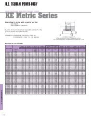
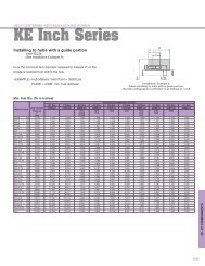
Installing to hubs with a guide portion<br />
when LtB2l<br />
(See Installation Example B)<br />
Installing to hubs without a guide portion<br />
(See Installation Example C)<br />
DN is the minimum hub diameter required to tolerate P’ or<br />
the pressure exerted from within the hub.<br />
Hub Material Yield Point = 35500 psi<br />
PL2AD = 5.038” min. hub diameter<br />
Installation Example B<br />
When installing to hubs<br />
with a guide portion,<br />
the hub configuration coefficient<br />
is as follows: K3=1.0<br />
Installation Example C<br />
When installing to hubs<br />
without a guide portion,<br />
the hub configuration coefficient<br />
is as follows: K3=1.0<br />
Min. Hub Dia. (DN in inches)<br />
Model Number<br />
Hub Contact<br />
Pressure<br />
P’<br />
(psi)<br />
Yield Point and Material examples<br />
147 Mpa 176 Mpa 206 Mpa 225 Mpa 245 Mpa 274 Mpa 294 Mpa 343 Mpa 392 Mpa 441 Mpa<br />
21300 psi 25500 psi 29900 psi 32600 psi 35500 psi 39700 psi 42600 psi 49700 psi 56900 psi 64000 psi<br />
1010<br />
304SS<br />
316SS<br />
1015<br />
1118<br />
1020 1030 1035<br />
1040<br />
1144<br />
PL3/4 AD 13924 4.038 3.411 3.065 2.918 2.799 2.667 2.596 2.466 2.375 2.308<br />
PL7/8 AD 13924 4.038 3.411 3.065 2.918 2.799 2.667 2.596 2.466 2.375 2.308<br />
PL1 AD 14939 4.693 3.849 3.410 3.229 3.082 2.924 2.839 2.684 2.577 2.498<br />
PL1-1/8 AD 13489 4.564 3.898 3.522 3.360 3.228 3.083 3.004 2.859 2.757 2.682<br />
PL1-3/16 AD 13489 4.552 3.887 3.512 3.351 3.220 3.074 2.996 2.851 2.750 2.674<br />
PL1-1/4 AD 14649 5.484 4.539 4.039 3.830 3.661 3.478 3.379 3.199 3.074 2.982<br />
PL1-3/8 AD 14649 5.491 4.545 4.044 3.835 3.666 3.482 3.383 3.203 3.078 2.986<br />
PL1-7/16 AD 12764 5.107 4.432 4.039 3.868 3.727 3.570 3.485 3.327 3.216 3.133<br />
PL1-1/2 AD 12764 5.107 4.432 4.039 3.868 3.727 3.570 3.485 3.327 3.216 3.133<br />
PL1-5/8 AD 15664 7.551 6.035 5.286 4.982 4.740 4.480 4.341 4.091 3.918 3.792<br />
PL1-11/16 AD 15664 7.551 6.035 5.286 4.982 4.740 4.480 4.341 4.091 3.918 3.792<br />
PL1-3/4 AD 15664 7.550 6.034 5.285 4.981 4.740 4.479 4.341 4.091 3.918 3.791<br />
PL1-7/8 AD 14649 7.313 6.053 5.386 5.107 4.882 4.637 4.506 4.266 4.010 3.977<br />
PL1-15/16 AD 14649 7.313 6.053 5.386 5.107 4.882 4.637 4.506 4.266 4.010 3.977<br />
PL2 AD 13779 7.219 6.121 5.511 5.250 5.038 4.805 4.679 4.447 4.285 4.165<br />
PL2-1/8 AD 13779 7.219 6.121 5.511 5.250 5.038 4.805 4.679 4.447 4.285 4.165<br />
PL2-3/16 AD 15954 9.338 7.376 6.429 6.048 5.746 5.422 5.250 4.941 4.728 4.572<br />
PL2-1/4 AD 15954 9.338 7.376 6.429 6.048 5.746 5.422 5.250 4.941 4.728 4.572<br />
PL2-3/8 AD 15954 9.306 7.350 6.406 6.027 5.726 5.403 5.232 4.923 4.711 4.556<br />
PL2-7/16 AD 12909 7.545 6.528 5.939 5.683 5.473 5.239 5.112 4.878 4.712 4.589<br />
PL2-1/2 AD 12909 7.545 6.528 5.939 5.683 5.473 5.239 5.112 4.878 4.712 4.589<br />
PL2-9/16 AD 12909 7.538 6.522 5.934 5.678 5.468 5.235 5.108 4.874 4.708 4.586<br />
PL2-5/8 AD 16535 12.197 9.380 8.089 7.579 7.180 6.754 6.530 6.127 5.851 5.650<br />
PL2-11/16 AD 16535 12.197 9.380 8.089 7.579 7.180 6.754 6.530 6.127 5.851 5.650<br />
PL2-3/4 AD 16535 12.197 9.380 8.089 7.579 7.180 6.754 6.530 6.127 5.851 5.650<br />
PL2-7/8 AD 15809 11.751 9.338 8.159 7.683 7.305 6.898 6.682 6.293 6.024 5.827<br />
PL2-15/16 AD 15809 11.751 9.338 8.159 7.683 7.305 6.898 6.682 6.293 6.024 5.827<br />
PL3 AD 16535 13.287 10.218 8.811 8.256 7.821 7.357 7.113 6.674 6.374 6.155<br />
PL3-3/8 AD 15809 12.773 10.150 8.868 8.351 7.940 7.498 7.263 6.840 6.548 6.334<br />
PL3-7/16 AD 16535 14.394 11.069 9.545 8.944 8.473 7.970 7.706 7.230 6.905 6.668<br />
PL3-1/2 AD 16535 14.394 11.069 9.545 8.944 8.473 7.970 7.706 7.230 6.905 6.668<br />
PL3-3/4 AD 15954 13.981 11.043 9.625 9.054 8.603 8.118 7.861 7.397 7.078 6.845<br />
PL3-15/16 AD 15664 14.596 11.665 10.217 9.630 9.162 8.659 8.392 7.907 7.574 7.329<br />
PL4 AD 15302 14.414 11.676 10.287 9.717 9.262 8.769 8.506 8.030 7.700 7.457<br />
PL4-7/16 AD 17260 20.022 14.778 12.555 11.702 11.041 10.344 9.979 9.329 8.887 8.567<br />
PL4-1/2 AD 17260 20.022 14.778 12.555 11.702 11.041 10.344 9.979 9.329 8.887 8.567<br />
PL4-15/16 AD 16099 18.971 14.891 12.945 12.166 11.551 10.891 10.542 9.913 9.481 9.165<br />
PL5 AD 16099 18.971 14.891 12.945 12.166 11.551 10.891 10.542 9.913 9.481 9.165<br />
PL5-1/2 AD 17550 24.054 17.410 14.695 13.665 12.871 12.038 11.604 10.831 10.308 9.929<br />
PL6 AD 17840 27.731 19.637 16.461 15.271 14.359 13.406 12.911 12.033 11.440 11.011<br />
PL6-1/2 AD 15954 23.346 18.440 16.072 15.119 14.365 13.555 13.126 12.352 11.819 11.429<br />
PL7 AD 16390 25.585 19.816 17.135 16.073 15.237 14.344 13.874 13.027 12.447 12.024<br />
PL7-1/2 AD 16390 27.164 21.039 18.193 17.064 16.177 15.230 14.730 13.831 13.216 12.766<br />
PL7-7/8 AD 15664 26.171 20.917 18.321 17.267 16.429 15.526 15.047 14.179 13.580 13.142<br />
PL8 AD 14664 24.422 20.204 17.973 17.041 16.290 15.472 15.033 14.233 13.676 13.265<br />
PL8-1/2 AD 17115 33.918 25.262 21.530 20.089 18.970 17.787 17.167 16.061 15.308 14.761<br />
PL9 AD 16457 32.520 25.105 21.682 20.327 19.263 18.129 17.531 16.456 15.719 15.182<br />
PL9-1/2 AD 15800 31.516 25.052 21.893 20.616 19.602 18.512 17.934 16.889 16.168 15.641<br />
PL10 AD 13199 26.378 22.678 20.563 19.649 18.900 18.071 17.621 16.792 16.208 15.775<br />
PL10-1/2 AD 13739 28.641 24.308 21.896 20.865 20.026 19.101 18.602 17.685 17.043 16.567<br />
PL11 AD 17115 42.321 31.520 26.863 25.066 23.669 22.193 21.420 20.040 19.100 18.418<br />
PL11-13/16 AD 17840 49.513 35.062 29.390 27.267 25.638 23.936 23.052 21.485 20.425 19.659<br />
4140<br />
1045<br />
1055<br />
AD Metric Series <strong>POWER</strong>-LOCK ® Specifications<br />
Dimensions<br />
Transmissible Transmissible Contact Pressure<br />
Locking Bolts<br />
Model Number<br />
Shaft O.D. Hub Counter I.D.<br />
inch<br />
Torque Thrust<br />
psi<br />
Tightening<br />
Tolerance<br />
Tolerance<br />
Shaft Hub Bore<br />
Torque Wt.<br />
d t1 D t2 L < Lt ft.lbs. lbs. P P’ Qty. Size ft.lbs. lbs.<br />
PL019X047 AD 0.7480<br />
1.8504<br />
1.181 1.378 1.614 282 9,127 34375 13924 6 M6 X 28 12.5 0.8<br />
PL020X047 AD 0.7874 1.8504 1.181 1.378 1.614 297 9,127 32634 13924 6 M6 X 28 12.5 0.8<br />
+0.0015"<br />
PL022X047 AD 0.8661 1.8504 1.181 1.378 1.614 325 9,127 29588 13924 6 M6 X 28 12.5 0.7<br />
-0.0013"<br />
-0<br />
PL024X050 AD 0.9449 1.9685 1.378 1.575 1.811 477 12,184 31039 14939 8 M6 X 30 12.5 0.9<br />
+0<br />
PL025X050 AD 0.9843 1.9685 1.378 1.575 1.811 499 12,184 29733 14939 8 M6 X 30 12.5 0.9<br />
PL028X055 AD 1.1024 2.1654<br />
1.378 1.575 1.811 557 12,184 26542 13489 8 M6 X 30 12.5 1.1<br />
PL030X055 AD 1.1811 2.1654 1.378 1.575 1.811 578 12,184 24802 13489 8 M6 X 30 12.5 1.0<br />
PL032X060 AD 1.2598<br />
2.3622 1.772 1.969 2.205 937 18,209 27413 14649 10 M6 X 35 12.5 1.6<br />
PL035X060 AD 1.3780 2.3622 1.772 1.969 2.205 1,011 18,209 24947 14649 10 M6 X 35 12.5 1.5<br />
PL038X065 AD 1.4961 2.5591 +0.0018" 2.047 2.244 2.480 1,232 20,007 21901 12764 11 M6 X 40 12.5 1.9<br />
PL040X065 AD 1.5748 -0.0015" 2.5591 -0 2.047 2.244 2.480 1,298 20,007 20886 12764 11 M6 X 40 12.5 1.8<br />
PL042X075 AD 1.6535 +0 2.9528 2.205 2.520 2.835 2,604 38,216 27848 15664 9 M8 X 50 30 3.0<br />
PL045X075 AD 1.7717 2.9528 2.205 2.520 2.835 2,818 38,216 25962 15664 9 M8 X 50 30 2.8<br />
PL048X080 AD 1.8898 3.1496 2.205 2.520 2.835 3,002 38,216 24367 14649 9 M8 X 50 30 3.1<br />
PL050X080 AD 1.9685 3.1496 2.205 2.520 2.835 3,105 38,216 23497 14649 9 M8 X 50 30 3.0<br />
PL055X085 AD 2.1654<br />
3.3465<br />
2.205 2.520 2.835 3,400 38,216 21321 13779 9 M8 X 50 30 3.3<br />
PL060X090 AD 2.3622 3.5433 2.205 2.520 2.835 4,551 46,758 23932 15954 11 M8 X 50 30 3.5<br />
PL065X095 AD 2.5591 -0.0018" 3.7402 +0.0021 2.205 2.520 2.835 4,986 46,758 18855 12909 11 M8 X 50 30 3.8<br />
PL070X110 AD 2.7559 +0 4.3307 -0 2.756 3.071 3.465 8,556 74,184 25962 16535 11 M10 X 70 60 7.0<br />
PL075X115 AD 2.9528 4.5276 2.756 3.071 3.465 9,072 74,184 24222 15809 11 M10 X 70 60 7.4<br />
PL080X120 AD 3.1496 4.7244 2.756 3.071 3.465 10,621 80,928 24802 16535 12 M10 X 70 60 7.7<br />
PL085X125 AD 3.3465<br />
4.9213<br />
2.756 3.071 3.465 11,285 80,928 23351 15809 12 M10 X 70 60 8.1<br />
PL090X130 AD 3.5433 5.1181 2.756 3.071 3.465 12,907 87,672 23932 16535 13 M10 X 70 60 8.5<br />
PL095X135 AD 3.7402 -0.0021" 5.3150 2.756 3.071 3.465 13,645 87,672 22626 15954 13 M10 X 70 60 8.9<br />
+0.0025"<br />
PL100X145 AD 3.9370 +0 5.7087 3.543 3.937 4.409 19,545 119,369 22771 15664 12 M12 X 90 105 14<br />
-0<br />
PL110X155 AD 4.3307 6.1024 3.543 3.937 4.409 23,381 129,485 22481 15954 13 M12 X 90 105 15<br />
PL120X165 AD 4.7244 6.4961 3.543 3.937 4.409 29,429 149,267 23787 17260 15 M12 X 90 105 16<br />
PL130X180 AD 5.1181<br />
7.0866 4.094 4.567 5.118 37,394 175,119 22191 16099 13 M14 X 90 166 18<br />
PL140X190 AD 5.5118 7.4803<br />
4.094 4.567 5.118 46,393 202,320 23787 17550 15 M14 X 90 166 19<br />
PL150X200 AD 5.9055 -0.0025" 7.8740 4.094 4.567 5.118 53,031 215,583 23787 17840 16 M14 X 90 166 20<br />
PL160X210 AD 6.2992 +0 8.2677 +0.0028" 4.094 4.567 5.118 60,111 229,296 23642 17840 17 M14 X 90 166 21<br />
PL170X225 AD 6.6929 8.8583 -0 5.276 5.748 6.378 78,181 278,752 21176 15954 15 M16 X 120 257 39<br />
PL180X235 AD 7.0866 9.2520 5.276 5.748 6.378 88,507 298,984 21321 16390 16 M16 X 120 257 41<br />
PL190X250 AD 7.4803<br />
9.8425 5.276 5.748 6.378 98,833 316,968 21466 16390 17 M16 X 120 257 47<br />
PL200X260 AD 7.8740 -0.0028" 10.2362<br />
5.276 5.748 6.378 103,996 316,968 20306 15664 17 M16 X 120 257 50<br />
+0.0032"<br />
PL220X285 AD 8.6614 +0 11.2205 5.276 5.748 6.378 134,974 375,416 21756 17115 20 M16 X 120 257 59<br />
-0<br />
PL240X305 AD 9.4488 12.0079 5.276 5.748 6.378 162,263 411,384 21901 17405 22 M16 X 120 257 63<br />
PL260X325 AD 10.2362<br />
12.7953<br />
5.276 5.748 6.378 175,539 411,384 16535 13199 22 M16 X 120 257 68<br />
-0.0032"<br />
+0.0035"<br />
PL280X355 AD 11.0236 13.9764 6.496 6.969 7.756 268,472 584,480 21756 17115 20 M20 X 150 499 103<br />
+0<br />
-0<br />
PL300X375 AD 11.8110 14.7638 6.496 6.969 7.756 316,413 642,928 22336 17840 22 M20 X 150 499 109<br />
More information at www.ustsubaki.com 22<br />
23<br />
More information at www.ustsubaki.com
U.S. TSUBAKI <strong>POWER</strong>-LOCK ®<br />
AD Metric Series<br />
DOUBLE TORQUE SERIES<br />
AE <strong>Inc</strong>h and Metric Series<br />
SELF CENTERING SERIES<br />
<strong>Tsubaki</strong>: The solution for shaft locking devices<br />
Installing to hubs with a guide portion<br />
when LtB2l<br />
(See Installation Example B)<br />
Installing to hubs without a guide portion<br />
(See Installation Example C)<br />
DN is the minimum hub diameter required to tolerate P’ or<br />
the pressure exerted from within the hub.<br />
Hub Material Yield Point = 35500 psi<br />
PL030X055AD = 3.229” min. hub diameter<br />
Installation Example B<br />
When installing to hubs<br />
with a guide portion,<br />
the hub configuration coefficient<br />
is as follows: K3=1.0<br />
Installation Example C<br />
When installing to hubs<br />
without a guide portion,<br />
the hub configuration coefficient<br />
is as follows: K3=1.0<br />
Features & Applications<br />
n Self-Centering Function<br />
Straight and narrow hubs can be used with AE Series<br />
<strong>POWER</strong>-LOCK ® .<br />
n Interchangeable <strong>POWER</strong>-LOCK AS Metric Series<br />
to AE Metric Series<br />
Same size inside diameter and outside diameter as<br />
AS Series <strong>POWER</strong>-LOCK in most cases.<br />
n Easy and Precise Positioning<br />
n Simple Construction<br />
Min. Hub Dia. (DN in inches)<br />
Model Number<br />
Hub Contact<br />
Pressure<br />
P’<br />
(psi)<br />
Yield Point and Material examples<br />
147 Mpa 176 Mpa 206 Mpa 225 Mpa 245 Mpa 274 Mpa 294 Mpa 343 Mpa 392 Mpa 441 Mpa<br />
21300 psi 25500 psi 29900 psi 32600 psi 35500 psi 39700 psi 42600 psi 49700 psi 56900 psi 64000 psi<br />
1010<br />
304SS<br />
316SS<br />
1015<br />
1118<br />
1020 1030 1035<br />
1040<br />
1144<br />
PL019X047 AD 13924 4.039 3.412 3.066 2.919 2.799 2.668 2.597 2.467 2.376 2.309<br />
PL020X047 AD 13924 4.039 3.412 3.066 2.919 2.799 2.668 2.597 2.467 2.376 2.309<br />
PL022X047 AD 13924 4.039 3.412 3.066 2.919 2.799 2.668 2.597 2.467 2.376 2.309<br />
PL024X050 AD 14939 4.692 3.848 3.410 3.228 3.082 2.923 2.838 2.683 2.576 2.497<br />
PL025X050 AD 14939 4.692 3.848 3.410 3.228 3.082 2.923 2.838 2.683 2.576 2.497<br />
PL028X055 AD 13489 4.565 3.898 3.522 3.361 3.229 3.083 3.005 2.860 2.758 2.682<br />
PL030X055 AD 13489 4.565 3.898 3.522 3.361 3.229 3.083 3.005 2.860 2.758 2.682<br />
PL032X060 AD 14649 5.485 4.540 4.039 3.830 3.662 3.478 3.379 3.200 3.075 2.982<br />
PL035X060 AD 14649 5.485 4.540 4.039 3.830 3.662 3.478 3.379 3.200 3.075 2.982<br />
PL038X065 AD 12764 5.107 4.432 4.039 3.868 3.727 3.570 3.485 3.327 3.216 3.133<br />
PL040X065 AD 12764 5.107 4.432 4.039 3.868 3.727 3.570 3.485 3.327 3.216 3.133<br />
PL042X075 AD 15664 7.550 6.034 5.285 4.981 4.740 4.479 4.341 4.091 3.918 3.791<br />
PL045X075 AD 15664 7.550 6.034 5.285 4.981 4.740 4.479 4.341 4.091 3.918 3.791<br />
PL048X080 AD 14649 7.313 6.053 5.386 5.107 4.882 4.637 4.506 4.266 4.010 3.977<br />
PL050X080 AD 14649 7.313 6.053 5.386 5.107 4.882 4.637 4.506 4.266 4.010 3.977<br />
PL055X085 AD 13779 7.219 6.121 5.511 5.250 5.038 4.805 4.679 4.447 4.285 4.165<br />
PL060X090 AD 15954 9.338 7.376 6.429 6.048 5.746 5.422 5.250 4.941 4.728 4.572<br />
PL065X095 AD 12909 7.545 6.528 5.939 5.683 5.473 5.239 5.112 4.878 4.712 4.589<br />
PL070X110 AD 16535 12.179 9.366 8.077 7.568 7.169 6.744 6.520 6.118 5.843 5.642<br />
PL075X115 AD 15809 11.751 9.338 8.159 7.683 7.305 6.898 6.682 6.293 6.024 5.827<br />
PL080X120 AD 16535 13.287 10.218 8.811 8.256 7.821 7.357 7.113 6.674 6.374 6.155<br />
PL085X125 AD 15809 12.773 10.150 8.868 8.351 7.940 7.498 7.263 6.840 6.548 6.334<br />
PL090X130 AD 16535 14.394 11.069 9.545 8.944 8.473 7.970 7.706 7.230 6.905 6.668<br />
PL095X135 AD 15954 14.008 11.064 9.643 9.071 8.619 8.133 7.876 7.411 7.091 6.857<br />
PL100X145 AD 15664 14.597 11.666 10.218 9.631 9.163 8.660 8.392 7.908 7.575 7.330<br />
PL110X155 AD 15954 16.083 12.703 11.071 10.415 9.896 9.338 9.042 8.509 8.142 7.873<br />
PL120X165 AD 17260 20.022 14.778 12.555 11.702 11.041 10.344 9.979 9.329 8.887 8.567<br />
PL130X180 AD 16099 18.971 14.891 12.945 12.166 11.551 10.891 10.542 9.913 9.481 9.165<br />
PL140X190 AD 17550 24.016 17.383 14.672 13.644 12.851 12.019 11.586 10.814 10.292 9.913<br />
PL150X200 AD 17840 26.410 18.702 15.677 14.544 13.675 12.767 12.296 11.460 10.895 10.486<br />
PL160X210 AD 17840 27.731 19.637 16.461 15.271 14.359 13.406 12.911 12.033 11.440 11.011<br />
PL170X225 AD 15954 23.346 18.440 16.072 15.119 14.365 13.555 13.126 12.352 11.819 11.429<br />
PL180X235 AD 16390 25.585 19.816 17.135 16.073 15.237 14.344 13.874 13.027 12.447 12.024<br />
PL190X250 AD 16390 27.218 21.081 18.229 17.098 16.209 15.260 14.759 13.859 13.242 12.792<br />
PL200X260 AD 15664 26.174 20.919 18.323 17.269 16.431 15.528 15.049 14.181 13.582 13.143<br />
PL220X285 AD 17115 33.918 25.262 21.530 20.089 18.970 17.787 17.167 16.061 15.308 14.761<br />
PL240X305 AD 17405 37.761 27.607 23.379 21.766 20.519 19.207 18.522 17.302 16.475 15.874<br />
PL260X325 AD 13199 26.378 22.678 20.563 19.649 18.900 18.071 17.621 16.792 16.208 15.775<br />
PL280X355 AD 17115 42.249 31.467 26.818 25.024 23.629 22.155 21.384 20.006 19.068 18.387<br />
PL300X375 AD 17840 49.519 35.067 29.394 27.270 25.641 23.939 23.055 21.487 20.428 19.662<br />
4140<br />
1045<br />
1055<br />
Locking Bolts<br />
Inner Ring<br />
Model Number<br />
<strong>Inc</strong>h Series: PL 2 AE<br />
AE Series<br />
Shaft Dia. (inch)<br />
<strong>POWER</strong>-LOCK ®<br />
Metric Series: PL 019 X 047 AE<br />
Series<br />
Outer Dia. (mm)<br />
Shaft Dia. (mm)<br />
<strong>POWER</strong>-LOCK ®<br />
Outer Ring<br />
More information at www.ustsubaki.com 24<br />
25<br />
More information at www.ustsubaki.com
U.S. TSUBAKI <strong>POWER</strong>-LOCK ®<br />
AE <strong>Inc</strong>h Series<br />
SELF CENTERING SERIES<br />
AE <strong>Inc</strong>h Series<br />
SELF CENTERING SERIES<br />
<strong>Tsubaki</strong>: The solution for shaft locking devices<br />
Installing to hubs with a guide portion<br />
when B≧2l<br />
(See Installation Example A)<br />
DN is the minimum hub diameter required to tolerate P’ or the<br />
pressure exerted from within the hub.<br />
Hub Material Yield Point = 35500 psi<br />
PL2AE = 5.061” min. hub diameter<br />
Installation Example A<br />
When installing to hubs<br />
with a guide portion,<br />
the hub configuration coefficient<br />
is as follows: K3=0.8<br />
AE <strong>Inc</strong>h Series <strong>POWER</strong>-LOCK ® Specifications<br />
Dimensions<br />
Transmissible Transmissible Contact Pressure<br />
Locking Bolts<br />
Shaft O.D. Hub Counter I.D.<br />
inch<br />
Torque Thrust psi<br />
Model Number<br />
Tightening<br />
d<br />
Tolerance<br />
t1 D<br />
Tolerance<br />
t2 < L2 L Lt t1 t2 D1 ft.lbs. lbs.<br />
Shaft<br />
P<br />
Hub Bore<br />
P’ Qty. Size<br />
Torque<br />
ft.lbs.<br />
Wt.<br />
lbs.<br />
PL3/4 AE 0.7500<br />
1.8504<br />
0.748 0.976 1.075 1.311 0.098 0.118 2.087 195 6,270 41363 13503 6 M6 X 18 12.5 0.6<br />
+0.0015"<br />
PL7/8 AE 0.8750 -0.0013" 1.8504 0.748 0.976 1.075 1.311 0.098 0.118 2.087 224 6,270 35535 13503 6 M6 X 18 12.5 0.6<br />
-0<br />
PL1 AE 1.0000 +0 1.9685 0.748 0.996 1.094 1.331 0.098 0.118 2.244 303 7,326 37525 14783 7 M6 X 18 12.5 0.6<br />
PL1-1/8 AE 1.1250 2.1654<br />
0.748 0.996 1.126 1.362 0.130 0.118 2.441 390 8,360 38093 15351 8 M6 X 18 12.5 0.8<br />
PL1-3/16 AE 1.1875<br />
2.1654 0.748 0.996 1.126 1.362 0.130 0.118 2.441 412 8,360 36103 15351 8 M6 X 18 12.5 0.7<br />
PL1-1/4 AE 1.2500 2.3622 0.807 1.075 1.217 1.453 0.142 0.118 2.638 542 10,450 38804 16346 10 M6 X 18 12.5 0.9<br />
PL1-3/8 AE 1.3750 2.3622 0.807 1.075 1.217 1.453 0.142 0.118 2.638 600 10,450 35251 16346 10 M6 X 18 12.5 0.9<br />
PL1-7/16 AE 1.4370 2.5591 0.807 1.083 1.224 1.461 0.142 0.118 2.874 621 10,450 34256 15067 10 M6 X 18 12.5 1.1<br />
PL1-1/2 AE 1.5000 -0.0015" 2.5591 +0.0018" 0.807 1.083 1.224 1.461 0.142 0.118 2.874 651 10,450 32834 15067 10 M6 X 18 12.5 1.1<br />
PL1-5/8 AE 1.6250 +0 2.9528 -0 0.925 1.213 1.370 1.685 0.157 0.118 3.268 1,178 17,402 41931 18905 9 M8 X 22 30 1.7<br />
PL1-11/16 AE 1.6875 2.9528 0.925 1.213 1.370 1.685 0.157 0.118 3.268 1,221 17,402 40368 18905 9 M8 X 22 30 1.7<br />
PL1-3/4 AE 1.7500 2.9528 0.925 1.213 1.370 1.685 0.157 0.118 3.268 1,265 17,402 38946 18905 9 M8 X 22 30 1.5<br />
PL1-7/8 AE 1.8750 3.1496 0.925 1.220 1.378 1.693 0.157 0.118 3.465 1,511 19,338 40794 19615 10 M8 X 22 30 1.8<br />
PL1-15/16 AE 1.9375 3.1496 0.925 1.220 1.378 1.693 0.157 0.118 3.465 1,561 19,338 39515 19615 10 M8 X 22 30 1.8<br />
PL2 AE 2.0000<br />
3.1496 0.925 1.220 1.378 1.693 0.157 0.118 3.465 1,612 19,338 38235 19615 10 M8 X 22 30 1.7<br />
PL1-1/8 AE 2.1250 3.3465<br />
0.925 1.213 1.370 1.685 0.157 0.118 3.701 1,713 19,338 35677 18478 10 M8 X 22 30 1.8<br />
PL1-3/16 AE 2.1875 3.3465 0.925 1.213 1.370 1.685 0.157 0.118 3.701 1,764 19,338 34540 18478 10 M8 X 22 30 2.0<br />
PL2-1/4 AE 2.2500 3.5433 0.925 1.213 1.370 1.685 0.157 0.118 3.898 1,814 19,140 33687 17483 10 M8 X 22 30 2.0<br />
PL2-3/8 AE 2.3750 3.5433 0.925 1.213 1.370 1.685 0.157 0.118 3.898 1,915 19,140 31839 17483 10 M8 X 22 30 2.0<br />
PL2-7/16 AE 2.4375 3.7402 0.925 1.213 1.370 1.685 0.157 0.118 4.094 2,356 23,100 37241 19900 12 M8 X 22 30 2.1<br />
PL2-1/2 AE 2.5000 -0.0018" 3.7402 +0.0021 0.925 1.213 1.370 1.685 0.157 0.118 4.094 2,421 23,100 36388 19900 12 M8 X 22 30 2.1<br />
PL2-9/16 AE 2.5625 +0 3.7402 -0 0.925 1.213 1.370 1.685 0.157 0.118 4.094 2,479 23,100 35393 19900 12 M8 X 22 30 2.1<br />
PL2-11/16 AE 2.6250 4.3307 1.102 1.437 1.614 2.008 0.177 0.157 4.724 3,440 30,580 36530 19047 10 M10 X 25 60 3.7<br />
PL2-3/4 AE 2.6875 4.3307 1.102 1.437 1.614 2.008 0.177 0.157 4.724 3,520 30,580 35677 19047 10 M10 X 25 60 3.7<br />
PL2-7/8 AE 2.7500 4.5276 1.102 1.437 1.614 2.008 0.177 0.157 4.921 3,679 30,580 34113 18194 10 M10 X 25 60 3.8<br />
PL2-15/16 AE 2.8750 4.5276 1.102 1.437 1.614 2.008 0.177 0.157 4.921 3,759 30,580 33403 18194 10 M10 X 25 60 3.9<br />
PL3 AE 2.9375 4.7244 1.102 1.437 1.614 2.008 0.177 0.157 5.118 4,611 36,740 39230 20895 12 M10 X 25 60 4.1<br />
PL3-1/4 AE 3.0000 4.9213<br />
1.102 1.437 1.614 2.008 0.177 0.157 5.315 4,994 36,740 36260 20184 12 M10 X 25 60 4.4<br />
PL3-3/8 AE 3.3750<br />
4.9213 1.102 1.437 1.614 2.008 0.177 0.157 5.315 5,190 36,740 34966 20184 12 M10 X 25 60 4.4<br />
PL3-7/16 AE 3.4375 5.1181 1.102 1.476 1.693 2.087 0.217 0.157 5.512 5,283 36,740 35819 19331 12 M10 X 25 60 4.7<br />
+0.0025"<br />
PL3-1/2 AE 3.5000 -0.0021" 5.1181 1.102 1.476 1.693 2.087 0.217 0.157 5.512 5,378 36,740 35108 19331 12 M10 X 25 60 4.7<br />
-0<br />
PL3-3/4 AE 3.7500 +0 5.3150 1.102 1.476 1.693 2.087 0.217 0.157 5.709 6,729 42,900 38235 21747 14 M10 X 25 60 4.8<br />
PL3-15/16 AE 3.9375 5.7087 1.339 1.732 1.969 2.362 0.236 0.157 6.102 7,567 45,980 31413 17910 15 M10 X 25 60 6.7<br />
PL4 AE 4.0000 5.7087 1.339 1.732 1.969 2.362 0.236 0.157 6.102 7,691 45,980 30986 17910 15 M10 X 25 60 6.7<br />
Min. Hub Dia. (DN in inches)<br />
Model Number<br />
Hub Contact<br />
Pressure<br />
P’<br />
(psi)<br />
Yield Point and Material examples<br />
147 Mpa 176 Mpa 206 Mpa 225 Mpa 245 Mpa 274 Mpa 294 Mpa 343 Mpa 392 Mpa 441 Mpa<br />
21300 psi 25500 psi 29900 psi 32600 psi 35500 psi 39700 psi 42600 psi 49700 psi 56900 psi 64000 psi<br />
1010<br />
304SS<br />
316SS<br />
1015<br />
1118<br />
1020 1030 1035<br />
1040<br />
1144<br />
PL3/4 AE 13503 3.234 2.907 2.702 2.610 2.533 2.445 2.397 2.307 2.243 2.194<br />
PL7/8 AE 13503 3.234 2.907 2.702 2.610 2.533 2.445 2.397 2.307 2.243 2.194<br />
PL1 AE 14783 3.678 3.250 2.992 2.877 2.782 2.675 2.617 2.508 2.431 2.373<br />
PL1-1/8 AE 15351 4.175 3.658 3.352 3.217 3.105 2.980 2.912 2.786 2.697 2.630<br />
PL1-3/16 AE 15351 4.175 3.658 3.352 3.217 3.105 2.980 2.912 2.786 2.697 2.630<br />
PL1-1/4 AE 16346 4.825 4.160 3.777 3.611 3.475 3.325 3.243 3.092 2.986 2.907<br />
PL1-3/8 AE 16346 4.825 4.160 3.777 3.611 3.475 3.325 3.243 3.092 2.986 2.907<br />
PL1-7/16 AE 15067 4.856 4.274 3.925 3.771 3.643 3.500 3.422 3.277 3.174 3.097<br />
PL1-1/2 AE 15067 4.856 4.274 3.925 3.771 3.643 3.500 3.422 3.277 3.174 3.097<br />
PL1-5/8 AE 18905 7.160 5.837 5.157 4.876 4.652 4.408 4.278 4.042 3.878 3.757<br />
PL1-11/16 AE 18905 7.160 5.837 5.157 4.876 4.652 4.408 4.278 4.042 3.878 3.757<br />
PL1-3/4 AE 18905 7.160 5.837 5.157 4.876 4.652 4.408 4.278 4.042 3.878 3.757<br />
PL1-7/8 AE 19615 8.077 6.448 5.645 5.319 5.061 4.782 4.634 4.366 4.181 4.046<br />
PL1-15/16 AE 19615 8.077 6.448 5.645 5.319 5.061 4.782 4.634 4.366 4.181 4.046<br />
PL2 AE 19615 8.077 6.448 5.645 5.319 5.061 4.782 4.634 4.366 4.181 4.046<br />
PL1-1/8 AE 18478 7.864 6.482 5.756 5.454 5.211 4.946 4.804 4.546 4.367 4.234<br />
PL1-3/16 AE 18478 7.864 6.482 5.756 5.454 5.211 4.946 4.804 4.546 4.367 4.234<br />
PL2-1/4 AE 17483 7.774 6.556 5.887 5.603 5.372 5.118 4.981 4.730 4.555 4.425<br />
PL2-3/8 AE 17483 7.774 6.556 5.887 5.603 5.372 5.118 4.981 4.730 4.555 4.425<br />
PL2-7/16 AE 19900 9.821 7.768 6.775 6.375 6.058 5.717 5.537 5.211 4.987 4.823<br />
PL2-1/2 AE 19900 9.821 7.768 6.775 6.375 6.058 5.717 5.537 5.211 4.987 4.823<br />
PL2-9/16 AE 19900 9.821 7.768 6.775 6.375 6.058 5.717 5.537 5.211 4.987 4.823<br />
PL2-11/16 AE 19047 10.616 8.620 7.602 7.184 6.849 6.487 6.294 5.943 5.700 5.521<br />
PL2-3/4 AE 19047 10.616 8.620 7.602 7.184 6.849 6.487 6.294 5.943 5.700 5.521<br />
PL2-7/8 AE 18194 10.426 8.654 7.710 7.315 6.996 6.648 6.461 6.120 5.883 5.708<br />
PL2-15/16 AE 18194 10.426 8.654 7.710 7.315 6.996 6.648 6.461 6.120 5.883 5.708<br />
PL3 AE 20895 13.577 10.344 8.889 8.318 7.872 7.398 7.149 6.701 6.396 6.174<br />
PL3-1/4 AE 20184 13.243 10.373 9.001 8.465 8.035 7.574 7.331 6.892 6.590 6.370<br />
PL3-3/8 AE 20184 13.243 10.373 9.001 8.465 8.035 7.574 7.331 6.892 6.590 6.370<br />
PL3-7/16 AE 19331 12.828 10.330 9.078 8.566 8.159 7.718 7.484 7.059 6.765 6.550<br />
PL3-1/2 AE 19331 12.828 10.330 9.078 8.566 8.159 7.718 7.484 7.059 6.765 6.550<br />
PL3-3/4 AE 21747 16.697 12.213 10.344 9.631 9.080 8.500 8.197 7.657 7.291 7.026<br />
PL3-15/16 AE 17910 12.889 10.769 9.625 9.143 8.753 8.327 8.098 7.678 7.386 7.170<br />
PL4 AE 17910 12.889 10.769 9.625 9.143 8.753 8.327 8.098 7.678 7.386 7.170<br />
4140<br />
1045<br />
1055<br />
More information at www.ustsubaki.com 26<br />
27<br />
More information at www.ustsubaki.com
U.S. TSUBAKI <strong>POWER</strong>-LOCK ®<br />
AE <strong>Inc</strong>h Series<br />
SELF CENTERING SERIES<br />
AE Metric Series<br />
SELF CENTERING SERIES<br />
<strong>Tsubaki</strong>: The solution for shaft locking devices<br />
Installing to hubs with a guide portion<br />
when L2B2l<br />
(See Installation Example B)<br />
Installing to hubs without a guide portion<br />
(See Installation Example C)<br />
DN is the minimum hub diameter required to tolerate P’ or<br />
the pressure exerted from within the hub.<br />
Hub Material Yield Point = 35500 psi<br />
PL2AE = 5.862” min. hub diameter<br />
Installation Example B<br />
When installing to hubs<br />
with a guide portion,the hub configuration<br />
coefficient is as follows: K3=1.0<br />
Installation Example C<br />
When installing to hubs<br />
without a guide portion, the hub configuration<br />
coefficient is as follows: K3=1.0<br />
Min. Hub Dia. (DN in inches)<br />
Model Number<br />
Hub Contact<br />
Pressure<br />
P’<br />
(psi)<br />
Yield Point and Material examples<br />
147 Mpa 176 Mpa 206 Mpa 225 Mpa 245 Mpa 274 Mpa 294 Mpa 343 Mpa 392 Mpa 441 Mpa<br />
21300 psi 25500 psi 29900 psi 32600 psi 35500 psi 39700 psi 42600 psi 49700 psi 56900 psi 64000 psi<br />
1010<br />
304SS<br />
316SS<br />
1015<br />
1118<br />
1020 1030 1035<br />
1040<br />
1144<br />
PL3/4 AE 13503 3.905 3.334 3.012 2.874 2.761 2.636 2.569 2.444 2.357 2.293<br />
PL7/8 AE 13503 3.905 3.334 3.012 2.874 2.761 2.636 2.569 2.444 2.357 2.293<br />
PL1 AE 14783 4.626 3.813 3.386 3.208 3.065 2.910 2.826 2.674 2.569 2.491<br />
PL1-1/8 AE 15351 5.367 4.340 3.821 3.608 3.438 3.254 3.157 2.979 2.856 2.766<br />
PL1-3/16 AE 15351 5.367 4.340 3.821 3.608 3.438 3.254 3.157 2.979 2.856 2.766<br />
PL1-1/4 AE 16346 6.500 5.045 4.366 4.096 3.884 3.658 3.538 3.323 3.175 3.068<br />
PL1-3/8 AE 16346 6.500 5.045 4.366 4.096 3.884 3.658 3.538 3.323 3.175 3.068<br />
PL1-7/16 AE 15067 6.173 5.041 4.458 4.217 4.024 3.814 3.702 3.498 3.357 3.253<br />
PL1-1/2 AE 15067 6.173 5.041 4.458 4.217 4.024 3.814 3.702 3.498 3.357 3.253<br />
PL1-5/8 AE 18905 12.047 7.648 6.226 5.721 5.342 4.954 4.755 4.405 4.172 4.004<br />
PL1-11/16 AE 18905 12.047 7.648 6.226 5.721 5.342 4.954 4.755 4.405 4.172 4.004<br />
PL1-3/4 AE 18905 12.047 7.648 6.226 5.721 5.342 4.954 4.755 4.405 4.172 4.004<br />
PL1-7/8 AE 19615 15.430 8.703 6.917 6.310 5.862 5.409 5.179 4.779 4.513 4.324<br />
PL1-15/16 AE 19615 15.430 8.703 6.917 6.310 5.862 5.409 5.179 4.779 4.513 4.324<br />
PL2 AE 19615 15.430 8.703 6.917 6.310 5.862 5.409 5.179 4.779 4.513 4.324<br />
PL2-1/8 AE 18478 12.521 8.361 6.892 6.359 5.955 5.537 5.322 4.943 4.689 4.505<br />
PL2-3/16 AE 18478 12.521 8.361 6.892 6.359 5.955 5.537 5.322 4.943 4.689 4.505<br />
PL2-1/4 AE 17483 11.267 8.193 6.926 6.444 6.072 5.681 5.478 5.115 4.869 4.690<br />
PL2-3/8 AE 17483 11.267 8.193 6.926 6.444 6.072 5.681 5.478 5.115 4.869 4.690<br />
PL2-7/16 AE 19900 20.141 10.626 8.354 7.597 7.042 6.484 6.202 5.713 5.390 5.160<br />
PL2-1/2 AE 19900 20.141 10.626 8.354 7.597 7.042 6.484 6.202 5.713 5.390 5.160<br />
PL2-9/16 AE 19900 20.141 10.626 8.354 7.597 7.042 6.484 6.202 5.713 5.390 5.160<br />
PL2-5/8 AE 19047 18.246 11.358 9.204 8.446 7.879 7.299 7.002 6.483 6.136 5.887<br />
PL2-11/16 AE 19047 18.246 11.358 9.204 8.446 7.879 7.299 7.002 6.483 6.136 5.887<br />
PL2-3/4 AE 18194 16.094 11.055 9.183 8.494 7.969 7.424 7.142 6.644 6.308 6.066<br />
PL2-7/8 AE 18194 16.094 11.055 9.183 8.494 7.969 7.424 7.142 6.644 6.308 6.066<br />
PL2-15/16 AE 20895 47.007 14.955 11.231 10.088 9.275 8.474 8.075 7.392 6.947 6.632<br />
PL3 AE 20184 29.732 14.394 11.183 10.136 9.376 8.614 8.231 7.569 7.133 6.823<br />
PL3-3/8 AE 20184 29.732 14.394 11.183 10.136 9.376 8.614 8.231 7.569 7.133 6.823<br />
PL3-7/16 AE 19331 23.133 13.771 11.055 10.116 9.418 8.707 8.345 7.713 7.293 6.992<br />
PL3-1/2 AE 19331 23.133 13.771 11.055 10.116 9.418 8.707 8.345 7.713 7.293 6.992<br />
PL3-3/4 AE 21747 na 18.797 13.393 11.879 10.833 9.825 9.330 8.493 7.953 7.573<br />
PL3-15/16 AE 17910 na 13.632 11.407 10.577 9.941 9.277 8.932 8.322 7.910 7.612<br />
PL4 AE 17910 na 13.632 11.407 10.577 9.941 9.277 8.932 8.322 7.910 7.612<br />
4140<br />
1045<br />
1055<br />
AE Metric Series <strong>POWER</strong>-LOCK ® Specifications<br />
Dimensions<br />
Transmissible Transmissible Contact Pressure Locking Bolts<br />
Model Number<br />
Shaft O.D. Hub Counter I.D.<br />
inch<br />
Torque Thrust psi<br />
Tightening<br />
Tolerance<br />
Tolerance<br />
Shaft Hub Bore<br />
Torque Wt.<br />
d t1 D t2 < L2 L Lt t1 t2 D1 ft.lbs. lbs. P P’ Qty. Size ft.lbs. lbs.<br />
PL019X047 AE 0.7480<br />
1.8504<br />
0.748 0.976 1.075 1.311 0.098 0.118 2.087 196 6,314 41627 13489 6 M6 X 18 12.5 0.62<br />
PL020X047 AE 0.7874 1.8504 0.748 0.976 1.075 1.311 0.098 0.118 2.087 202 6,314 39451 13489 6 M6 X 18 12.5 0.59<br />
-0.0013"<br />
PL022X047 AE 0.8661 -0.0013" 1.8504 0.748 0.976 1.075 1.311 0.098 0.118 2.087 224 6,314 35970 13489 6 M6 X 18 12.5 0.57<br />
+0<br />
PL024X050 AE 0.9449 +0 1.9685 0.748 0.996 1.094 1.331 0.098 0.118 2.244 289 7,370 39741 14794 7 M6 X 18 12.5 0.06<br />
PL025X050 AE 0.9843 1.9685 0.748 0.996 1.094 1.331 0.098 0.118 2.244 304 7,370 40901 14794 7 M6 X 18 12.5 0.64<br />
PL028X055 AE 1.1024 2.1654<br />
0.748 0.996 1.126 1.362 0.130 0.118 2.441 383 8,426 39016 15374 8 M6 X 18 12.5 0.77<br />
PL030X055 AE 1.1811 2.1654 0.748 0.996 1.126 1.362 0.130 0.118 2.441 412 8,426 36405 15374 8 M6 X 18 12.5 0.75<br />
PL032X060 AE 1.2598<br />
2.3622 0.807 1.075 1.217 1.453 0.142 0.118 2.638 550 10,538 38726 16390 10 M6 X 18 12.5 0.97<br />
PL035X060 AE 1.3780 2.3622 0.807 1.075 1.217 1.453 0.142 0.118 2.638 607 10,538 35390 16390 10 M6 X 18 12.5 0.90<br />
PL038X065 AE 1.4961 2.5591 +0.0015" 0.807 1.083 1.224 1.461 0.142 0.118 2.874 658 10,538 33069 15084 10 M6 X 18 12.5 1.06<br />
-0.0015"<br />
PL040X065 AE 1.5748 2.5591 -0 0.807 1.083 1.224 1.461 0.142 0.118 2.874 687 10,538 31474 15084 10 M6 X 18 12.5 0.99<br />
+0<br />
PL042X075 AE 1.6535 2.9528 0.925 1.213 1.370 1.685 0.157 0.118 3.268 1,210 17,534 41336 18855 9 M8 X 22 30 1.67<br />
PL045X075 AE 1.7717 2.9528 0.925 1.213 1.370 1.685 0.157 0.118 3.268 1,291 17,534 38581 18855 9 M8 X 22 30 1.6<br />
PL048X080 AE 1.8898 3.1496 0.925 1.220 1.378 1.693 0.157 0.118 3.465 1,519 19,492 40611 19725 10 M8 X 22 30 1.8<br />
PL050X080 AE 1.9685 3.1496 0.925 1.220 1.378 1.693 0.157 0.118 3.465 1,593 19,492 39161 19725 10 M8 X 22 30 1.7<br />
PL055X085 AE 2.1654<br />
3.3465<br />
0.925 1.213 1.370 1.685 0.157 0.118 3.701 1,733 19,492 35100 18565 10 M8 X 22 30 1.8<br />
PL060X090 AE 2.3622 3.5433 0.925 1.213 1.370 1.685 0.157 0.118 3.898 1,881 19,492 31764 17695 10 M8 X 22 30 2.0<br />
PL065X095 AE 2.5591 -0.0018" 3.7402 +0.0018" 0.925 1.213 1.370 1.685 0.157 0.118 4.094 2,456 23,320 35680 19871 12 M8 X 22 30 2.1<br />
PL070X110 AE 2.7559 +0 4.3307 -0 1.102 1.437 1.614 2.008 0.177 0.157 4.724 3,540 30,800 35825 19145 10 M10 X 25 60 3.7<br />
PL075X115 AE 2.9528 4.5276 1.102 1.437 1.614 2.008 0.177 0.157 4.921 3,762 30,800 33359 18275 10 M10 X 25 60 3.9<br />
PL080X120 AE 3.1496 4.7244 1.102 1.437 1.614 2.008 0.177 0.157 5.118 4,846 36,960 37710 21031 12 M10 X 25 60 4.2<br />
PL085X125 AE 3.3465<br />
4.9213<br />
1.102 1.437 1.614 2.008 0.177 0.157 5.315 5,133 36,960 35390 20161 12 M10 X 25 60 4.4<br />
PL090X130 AE 3.5433 5.1181 1.102 1.476 1.693 2.087 0.217 0.157 5.512 5,495 36,960 34955 19435 12 M10 X 25 60 4.7<br />
PL095X135 AE 3.7402 -0.0021" 5.3150 1.102 1.476 1.693 2.087 0.217 0.157 5.709 6,719 43,340 38726 21901 14 M10 X 25 60 4.9<br />
+0.0021"<br />
PL100X145 AE 3.9370 +0 5.7087 1.339 1.732 1.969 2.362 0.236 0.157 6.102 7,597 46,420 31619 17840 15 M10 X 25 60 6.8<br />
-0<br />
PL110X155 AE 4.3307 6.1024 1.339 1.732 1.969 2.362 0.236 0.157 6.575 8,408 46,420 28718 16825 15 M10 X 25 60 7.4<br />
PL120X165 AE 4.7244 6.4961 1.339 1.732 1.969 2.362 0.236 0.157 6.969 10,990 55,660 31619 18855 18 M10 X 25 60 7.9<br />
PL130X180 AE 5.1181 7.0866 1.496 1.969 2.244 2.717 0.276 0.236 7.677 14,456 67,540 31039 18710 15 M12 X 35 105 11.1<br />
-0.0025"<br />
PL140X190 AE 5.5118 7.4803 +0.0025" 1.496 1.969 2.244 2.717 0.276 0.236 8.071 15,563 67,540 28718 17840 15 M12 X 35 105 11.8<br />
+0<br />
PL150X200 AE 5.9055 7.8740 -0 1.496 1.969 2.283 2.756 0.315 0.236 8.465 19,914 80,960 32054 20306 18 M12 X 35 105 12.8<br />
More information at www.ustsubaki.com 28<br />
29<br />
More information at www.ustsubaki.com
U.S. TSUBAKI <strong>POWER</strong>-LOCK ®<br />
AE Metric Series<br />
SELF CENTERING SERIES<br />
AE Metric Series<br />
SELF CENTERING SERIES<br />
<strong>Tsubaki</strong>: The solution for shaft locking devices<br />
Installing to hubs with a guide portion<br />
when B≧2l<br />
(See Installation Example A)<br />
DN is the minimum hub diameter required to tolerate P’ or the<br />
pressure exerted from within the hub.<br />
Hub Material Yield Point = 35500 psi<br />
PL030X055AE = 3.107” min. hub diameter<br />
Installation Example A<br />
When installing to hubs<br />
with a guide portion,<br />
the hub configuration coefficient<br />
is as follows: K3=0.8<br />
Installing to hubs with a guide portion<br />
when L2B2l<br />
(See Installation Example B)<br />
Installing to hubs without a guide portion<br />
(See Installation Example C)<br />
DN is the minimum hub diameter required to tolerate P’ or<br />
the pressure exerted from within the hub.<br />
Hub Material Yield Point = 35500 psi<br />
PL030X055AE = 3.441” min. hub diameter<br />
Installation Example B<br />
When installing to hubs<br />
with a guide portion,the hub configuration<br />
coefficient is as follows: K3=1.0<br />
Installation Example C<br />
When installing to hubs<br />
without a guide portion, the hub configuration<br />
coefficient is as follows: K3=1.0<br />
Min. Hub Dia. (DN in inches)<br />
Model Number<br />
Hub Contact<br />
Pressure<br />
P’<br />
(psi)<br />
Yield Point and Material examples<br />
147 Mpa 176 Mpa 206 Mpa 225 Mpa 245 Mpa 274 Mpa 294 Mpa 343 Mpa 392 Mpa 441 Mpa<br />
21300 psi 25500 psi 29900 psi 32600 psi 35500 psi 39700 psi 42600 psi 49700 psi 56900 psi 64000 psi<br />
1010<br />
304SS<br />
316SS<br />
1015<br />
1118<br />
1020 1030 1035<br />
1040<br />
1144<br />
PL019X047 AE 13490 3.231 2.905 2.701 2.609 2.532 2.445 2.397 2.307 2.242 2.194<br />
PL020X047 AE 13490 3.231 2.905 2.701 2.609 2.532 2.445 2.397 2.307 2.242 2.194<br />
PL022X047 AE 13490 3.231 2.905 2.701 2.609 2.532 2.445 2.397 2.307 2.242 2.194<br />
PL024X050 AE 14800 3.680 3.252 2.993 2.878 2.783 2.676 2.618 2.509 2.432 2.374<br />
PL025X050 AE 14800 3.680 3.252 2.993 2.878 2.783 2.676 2.618 2.509 2.432 2.374<br />
PL028X055 AE 15380 4.180 3.662 3.354 3.219 3.107 2.982 2.914 2.787 2.698 2.631<br />
PL030X055 AE 15380 4.180 3.662 3.354 3.219 3.107 2.982 2.914 2.787 2.698 2.631<br />
PL032X060 AE 16400 4.838 4.167 3.782 3.616 3.479 3.328 3.246 3.094 2.987 2.908<br />
PL035X060 AE 16400 4.838 4.167 3.782 3.616 3.479 3.328 3.246 3.094 2.987 2.908<br />
PL038X065 AE 15090 4.861 4.277 3.927 3.773 3.645 3.501 3.423 3.278 3.175 3.097<br />
PL040X065 AE 15090 4.861 4.277 3.927 3.773 3.645 3.501 3.423 3.278 3.175 3.097<br />
PL042X075 AE 18860 7.134 5.823 5.148 4.869 4.645 4.403 4.274 4.038 3.875 3.755<br />
PL045X075 AE 18860 7.134 5.823 5.148 4.869 4.645 4.403 4.274 4.038 3.875 3.755<br />
PL048X080 AE 19730 8.150 6.484 5.668 5.338 5.076 4.794 4.645 4.375 4.188 4.052<br />
PL050X080 AE 19730 8.150 6.484 5.668 5.338 5.076 4.794 4.645 4.375 4.188 4.052<br />
PL055X085 AE 18570 7.913 6.509 5.774 5.469 5.223 4.956 4.813 4.553 4.372 4.239<br />
PL060X090 AE 17700 7.884 6.619 5.930 5.638 5.402 5.143 5.003 4.748 4.569 4.438<br />
PL065X095 AE 19880 9.797 7.757 6.767 6.369 6.053 5.713 5.533 5.208 4.985 4.821<br />
PL070X110 AE 19150 10.697 8.661 7.629 7.206 6.868 6.502 6.307 5.953 5.708 5.529<br />
PL075X115 AE 18280 10.486 8.686 7.732 7.333 7.011 6.660 6.472 6.129 5.890 5.714<br />
PL080X120 AE 21040 13.761 10.422 8.936 8.356 7.903 7.423 7.170 6.718 6.410 6.185<br />
PL085X125 AE 20170 13.216 10.361 9.002 8.459 8.030 7.570 7.327 6.889 6.588 6.368<br />
PL090X130 AE 19440 12.935 10.384 9.113 8.595 8.182 7.737 7.501 7.072 6.776 6.559<br />
PL095X135 AE 21910 16.992 12.324 10.409 9.682 9.121 8.532 8.225 7.679 7.309 7.040<br />
PL100X145 AE 17850 12.828 10.735 9.602 9.124 8.737 8.313 8.086 7.669 7.378 7.163<br />
PL110X155 AE 16830 12.836 10.969 9.914 9.461 9.091 8.682 8.461 8.054 7.768 7.556<br />
PL120X165 AE 18860 15.695 12.810 11.325 10.712 10.220 9.687 9.402 8.884 8.525 8.261<br />
PL130X180 AE 18720 16.937 13.878 12.290 11.633 11.105 10.531 10.225 9.667 9.280 8.995<br />
PL140X190 AE 17850 16.809 14.066 12.582 11.956 11.449 10.893 10.595 10.049 9.668 9.386<br />
PL150X200 AE 20310 21.420 16.703 14.483 13.598 12.900 12.154 11.760 11.051 10.564 10.208<br />
4140<br />
1045<br />
1055<br />
Min. Hub Dia. (DN in inches)<br />
Model Number<br />
Hub Contact<br />
Pressure<br />
P’<br />
(psi)<br />
Yield Point and Material examples<br />
147 Mpa 176 Mpa 206 Mpa 225 Mpa 245 Mpa 274 Mpa 294 Mpa 343 Mpa 392 Mpa 441 Mpa<br />
21300 psi 25500 psi 29900 psi 32600 psi 35500 psi 39700 psi 42600 psi 49700 psi 56900 psi 64000 psi<br />
1010<br />
304SS<br />
316SS<br />
1015<br />
1118<br />
1020 1030 1035<br />
1040<br />
1144<br />
PL019X047 AE 13490 3.901 3.331 3.001 2.872 2.759 2.635 2.568 2.444 2.357 2.292<br />
PL020X047 AE 13490 3.901 3.331 3.001 2.872 2.759 2.635 2.568 2.444 2.357 2.292<br />
PL022X047 AE 13490 3.901 3.331 3.001 2.872 2.759 2.635 2.568 2.444 2.357 2.292<br />
PL024X050 AE 14800 4.631 3.815 3.388 3.210 3.066 2.910 2.827 2.675 2.569 2.491<br />
PL025X050 AE 14800 4.631 3.815 3.388 3.210 3.066 2.910 2.827 2.675 2.569 2.491<br />
PL028X055 AE 15380 5.379 4.346 3.825 3.611 3.441 3.257 3.158 2.980 2.857 2.767<br />
PL030X055 AE 15380 5.379 4.346 3.825 3.611 3.441 3.257 3.158 2.980 2.857 2.767<br />
PL032X060 AE 16400 6.532 5.059 4.375 4.104 3.890 3.662 3.542 3.326 3.178 3.070<br />
PL035X060 AE 16400 6.532 5.059 4.375 4.104 3.890 3.662 3.542 3.326 3.178 3.070<br />
PL038X065 AE 15090 6.183 5.047 4.461 4.220 4.026 3.816 3.704 3.500 3.358 3.254<br />
PL040X065 AE 15090 6.183 5.047 4.461 4.220 4.026 3.816 3.704 3.500 3.358 3.254<br />
PL042X075 AE 18860 11.919 7.616 6.209 5.708 5.332 4.946 4.748 4.400 4.168 4.000<br />
PL045X075 AE 18860 11.919 7.616 6.209 5.708 5.332 4.946 4.748 4.400 4.168 4.000<br />
PL048X080 AE 19730 15.975 8.796 6.962 6.343 5.889 5.429 5.196 4.791 4.523 4.332<br />
PL050X080 AE 19730 15.975 8.796 6.962 6.343 5.889 5.429 5.196 4.791 4.523 4.332<br />
PL055X085 AE 18570 12.731 8.422 6.925 6.384 5.975 5.553 5.336 4.953 4.697 4.512<br />
PL060X090 AE 17700 11.623 8.324 7.002 6.504 6.121 5.719 5.511 5.140 4.889 4.707<br />
PL065X095 AE 19880 na 10.596 8.339 7.586 7.034 6.478 6.197 5.709 5.387 5.157<br />
PL070X110 AE 19150 na 11.458 9.256 8.485 7.910 7.323 7.023 6.498 6.148 5.897<br />
PL075X115 AE 18280 na 11.127 9.223 8.525 7.994 7.443 7.159 6.656 6.318 6.074<br />
PL080X120 AE 21040 na 15.203 11.333 10.160 9.330 8.515 8.109 7.417 6.966 6.647<br />
PL085X125 AE 20170 na 14.359 11.167 10.125 9.367 8.608 8.225 7.565 7.130 6.820<br />
PL090X130 AE 19440 na 13.905 11.122 10.166 9.457 8.737 8.371 7.732 7.308 7.004<br />
PL095X135 AE 21910 na na 13.541 11.981 10.909 9.880 9.376 8.525 7.978 7.594<br />
PL100X145 AE 17850 na na 11.366 10.544 9.915 9.256 8.915 8.308 7.899 7.603<br />
PL110X155 AE 16830 na na 11.543 10.793 10.208 9.587 9.261 8.677 8.279 7.989<br />
PL120X165 AE 18860 na na 13.659 12.557 11.731 10.881 10.445 9.680 9.169 8.802<br />
PL130X180 AE 18720 na na 14.781 13.608 12.725 11.814 11.347 10.525 9.974 9.579<br />
PL140X190 AE 17850 na na 14.893 13.817 12.992 12.129 11.681 10.887 10.350 9.962<br />
PL150X200 AE 20310 na na 18.029 16.317 15.078 13.840 13.218 12.146 11.441 10.940<br />
4140<br />
1045<br />
1055<br />
More information at www.ustsubaki.com 30<br />
31<br />
More information at www.ustsubaki.com
U.S. TSUBAKI <strong>POWER</strong>-LOCK ®<br />
FL <strong>Inc</strong>h and Metric Series<br />
FLUSH-MOUNT SELF-CENTERING STYLE<br />
FL <strong>Inc</strong>h Series<br />
FLUSH-MOUNT SELF-CENTERING STYLE<br />
<strong>Tsubaki</strong>: The solution for shaft locking devices<br />
Features & Applications<br />
n Self-Centering Function<br />
Straight and narrow hubs can be used with FL Series<br />
<strong>POWER</strong>-LOCK ® .<br />
n Interchangeable <strong>POWER</strong>-LOCK AS Series to<br />
FL Series<br />
n Easy and Precise Positioning<br />
n Simple Construction<br />
Tap Holes for Removal<br />
FL <strong>Inc</strong>h Series <strong>POWER</strong>-LOCK ® Specifications<br />
Locking Bolts<br />
Inner Ring<br />
Model Number<br />
<strong>Inc</strong>h Series: PL 2 FL<br />
FL Series<br />
Shaft Dia. (inch)<br />
<strong>POWER</strong>-LOCK ®<br />
Metric Series: PL 019 X 047 FL<br />
Series<br />
Outer Dia. (mm)<br />
Shaft Dia. (mm)<br />
<strong>POWER</strong>-LOCK ®<br />
Outer Ring<br />
Dimensions<br />
Transmissible Transmissible Contact Pressure<br />
Locking Bolts<br />
Model Number<br />
Shaft O.D. Hub Counter I.D.<br />
inch<br />
Torque Thrust<br />
psi<br />
Tightening<br />
Tolerance<br />
Tolerance<br />
Shaft Hub Bore<br />
Torque Wt.<br />
d t1 D t2 < L Lt ft.lbs. lbs. P P’ Qty. Size ft.lbs. lbs.<br />
PL3/4 FL 0.7500<br />
1.8504<br />
0.748 1.075 1.311 202 6,452 40321 13779 4 M6 X 18 12.5 0.6<br />
+0.0015"<br />
PL7/8 FL 0.8750 -0.0013" 1.8504 0.748 1.075 1.311 235 6,452 36405 13779 4 M6 X 18 12.5 0.6<br />
-0<br />
PL1 FL 1.0000 +0 1.9685 0.748 1.094 1.331 336 8,070 41046 16099 5 M6 X 18 12.5 0.6<br />
PL1-1/8 FL 1.1250 2.1654<br />
0.748 1.126 1.362 454 9,689 41046 17550 6 M6 X 18 12.5 0.8<br />
PL1-3/16 FL 1.1875<br />
2.1654 0.748 1.126 1.362 479 9,689 38871 17550 6 M6 X 18 12.5 0.7<br />
PL1-1/4 FL 1.2500 2.3622 0.807 1.217 1.453 589 11,307 39306 17405 7 M6 X 18 12.5 0.9<br />
PL1-3/8 FL 1.3750 2.3622 0.807 1.217 1.453 740 12,904 40901 20016 8 M6 X 18 12.5 0.9<br />
PL1-7/16 FL 1.4370 2.5591 0.807 1.224 1.461 774 12,904 38436 18420 8 M6 X 18 12.5 1.1<br />
+0.0018"<br />
PL1-1/2 FL 1.5000 -0.0015" 2.5591 0.807 1.224 1.461 908 14,522 41481 20741 9 M6 X 18 12.5 1.1<br />
-0<br />
PL1-5/8 FL 1.6250 +0 2.9528 0.925 1.370 1.685 1,212 17,894 41191 19290 6 M8 X 22 30 1.7<br />
PL1-11/16 FL 1.6875 2.9528 0.925 1.370 1.685 1,258 17,894 41336 19290 6 M8 X 22 30 1.7<br />
PL1-3/4 FL 1.7500 2.9528 0.925 1.370 1.685 1,305 17,894 39886 19290 6 M8 X 22 30 1.5<br />
PL1-7/8 FL 1.8750 3.1496 0.925 1.370 1.685 1,398 17,894 37275 18130 6 M8 X 22 30 1.8<br />
PL1-15/16 FL 1.9375 3.1496 0.925 1.370 1.685 1,685 20,884 40321 21176 7 M8 X 22 30 1.8<br />
PL2 FL 2.0000<br />
3.1496<br />
0.925 1.370 1.685 1,740 20,884 39016 21176 7 M8 X 22 30 1.8<br />
PL2-1/8 FL 2.1250 3.3465 0.925 1.370 1.685 1,848 20,884 38291 19871 7 M8 X 22 30 1.8<br />
PL2-3/16 FL 2.1875 3.3465 0.925 1.370 1.685 1,903 20,884 41481 19871 7 M8 X 22 30 2.0<br />
PL2-1/4 FL 2.2500 3.5433 0.925 1.370 1.685 2,236 23,829 41336 21466 8 M8 X 22 30 2.0<br />
PL2-3/8 FL 2.3750 3.5433 0.925 1.370 1.685 2,361 23,829 43657 21466 8 M8 X 22 30 2.0<br />
PL2-7/16 FL 2.4375 3.7402 0.925 1.370 1.685 2,726 26,751 41191 22916 9 M8 X 22 30 2.1<br />
PL2-1/2 FL 2.5000 -0.0018" 3.7402 +0.0021 0.925 1.370 1.685 2,795 26,751 40176 22916 9 M8 X 22 30 2.1<br />
PL2-9/16 FL 2.5625 +0 3.7402 -0 0.925 1.370 1.685 2,865 26,751 40901 22916 9 M8 X 22 30 2.1<br />
PL2-11/16 FL 2.6250 4.3307 1.102 1.614 2.008 3,711 33,046 39306 20451 7 M10 X 25 60 3.7<br />
PL2-3/4 FL 2.6875 4.3307 1.102 1.614 2.008 3,798 33,046 38436 20451 7 M10 X 25 60 3.9<br />
PL2-7/8 FL 2.7500 4.5276 1.102 1.614 2.008 3,970 33,046 36695 19580 7 M10 X 25 60 3.8<br />
PL2-15/16 FL 2.8750 4.5276 1.102 1.614 2.008 4,636 37,991 41046 22336 8 M10 X 25 60 3.9<br />
PL3 FL 2.9375 4.7244 1.102 1.614 2.008 4,735 37,991 40176 21466 8 M10 X 25 60 4.1<br />
PL3-1/4 FL 3.0000 4.9213 1.102 1.614 2.008 5,130 37,991 38001 20596 8 M10 X 25 60 4.4<br />
PL3-3/8 FL 3.3750<br />
4.9213<br />
1.102 1.614 2.008 5,993 42,712 41046 23206 9 M10 X 25 60 4.4<br />
PL3-7/16 FL 3.4375 5.1181 1.102 1.693 2.087 6,104 42,712 41191 22191 9 M10 X 25 60 4.7<br />
PL3-1/2 FL 3.5000 -0.0021" 5.1181 +0.0025" 1.102 1.693 2.087 6,215 42,712 40466 22191 9 M10 X 25 60 4.7<br />
PL3-3/4 FL 3.7500 +0 5.3150 -0 1.102 1.693 2.087 6,659 42,712 37855 21466 9 M10 X 25 60 4.8<br />
PL3-15/16 FL 3.9375 5.7087 1.339 1.969 2.362 9,322 56,874 38581 21901 12 M10 X 25 60 6.7<br />
PL4 FL 4.0000 5.7087 1.339 1.969 2.362 9,470 56,874 40901 21901 12 M10 X 25 60 6.7<br />
More information at www.ustsubaki.com 32<br />
33<br />
More information at www.ustsubaki.com
U.S. TSUBAKI <strong>POWER</strong>-LOCK ®<br />
<strong>Tsubaki</strong>: The solution for shaft locking devices<br />
FL <strong>Inc</strong>h Series<br />
FLUSH-MOUNT SELF-CENTERING STYLE<br />
FL <strong>Inc</strong>h Series<br />
FLUSH-MOUNT SELF-CENTERING STYLE<br />
Installing to hubs with a guide portion<br />
when B≧2l<br />
(See Installation Example A)<br />
DN is the minimum hub diameter required to tolerate P’ or the<br />
pressure exerted from within the hub.<br />
Hub Material Yield Point = 35500 psi<br />
PL2FL = 5.282” min. hub diameter<br />
Installation Example A<br />
When installing to hubs<br />
with a guide portion,<br />
the hub configuration coefficient<br />
is as follows: K3=0.8<br />
Installing to hubs with a guide portion<br />
when L2B2l<br />
(See Installation Example B)<br />
Installing to hubs without a guide portion<br />
(See Installation Example C)<br />
DN is the minimum hub diameter required to tolerate P’ or<br />
the pressure exerted from within the hub.<br />
Hub Material Yield Point = 35500 psi<br />
PL2FL = 6.242” min. hub diameter<br />
Installation Example B<br />
When installing to hubs<br />
with a guide portion,the hub configuration<br />
coefficient is as follows: K3=1.0<br />
Installation Example C<br />
When installing to hubs<br />
without a guide portion, the hub configuration<br />
coefficient is as follows: K3=1.0<br />
Min. Hub Dia. (DN in inches)<br />
Model Number<br />
Hub Contact<br />
Pressure<br />
P’<br />
(psi)<br />
Yield Point and Material examples<br />
147 Mpa 176 Mpa 206 Mpa 225 Mpa 245 Mpa 274 Mpa 294 Mpa 343 Mpa 392 Mpa 441 Mpa<br />
21300 psi 25500 psi 29900 psi 32600 psi 35500 psi 39700 psi 42600 psi 49700 psi 56900 psi 64000 psi<br />
1010<br />
304SS<br />
316SS<br />
1015<br />
1118<br />
1020 1030 1035<br />
1040<br />
1144<br />
PL3/4 FL 13747 3.274 2.934 2.723 2.628 2.548 2.458 2.409 2.317 2.251 2.201<br />
PL7/8 FL 13747 3.274 2.934 2.723 2.628 2.548 2.458 2.409 2.317 2.251 2.201<br />
PL1 FL 16153 3.975 3.438 3.127 2.993 2.882 2.758 2.692 2.568 2.481 2.416<br />
PL1-1/8 FL 17621 4.795 4.032 3.615 3.438 3.295 3.137 3.053 2.898 2.789 2.709<br />
PL1-3/16 FL 17621 4.795 4.032 3.615 3.438 3.295 3.137 3.053 2.898 2.789 2.709<br />
PL1-1/4 FL 17466 5.177 4.368 3.922 3.733 3.579 3.410 3.320 3.153 3.036 2.949<br />
PL1-3/8 FL 19961 6.235 4.922 4.289 4.034 3.833 3.616 3.502 3.295 3.153 3.048<br />
PL1-7/16 FL 18426 5.991 4.944 4.393 4.164 3.979 3.778 3.670 3.473 3.337 3.236<br />
PL1-1/2 FL 20729 7.238 5.553 4.784 4.481 4.244 3.991 3.858 3.619 3.456 3.337<br />
PL1-5/8 FL 19304 7.385 5.952 5.232 4.938 4.703 4.450 4.315 4.070 3.901 3.777<br />
PL1-11/16 FL 19304 7.385 5.952 5.232 4.938 4.703 4.450 4.315 4.070 3.901 3.777<br />
PL1-3/4 FL 19304 7.385 5.952 5.232 4.938 4.703 4.450 4.315 4.070 3.901 3.777<br />
PL1-7/8 FL 18097 7.204 5.993 5.345 5.074 4.854 4.614 4.485 4.250 4.086 3.965<br />
PL1-15/16 FL 21114 9.250 6.980 5.977 5.586 5.282 4.958 4.789 4.485 4.278 4.128<br />
PL2 FL 21114 9.250 6.980 5.977 5.586 5.282 4.958 4.789 4.485 4.278 4.128<br />
PL1-1/8 FL 19872 8.766 6.941 6.055 5.699 5.416 5.112 4.951 4.660 4.460 4.314<br />
PL1-3/16 FL 19872 8.766 6.941 6.055 5.699 5.416 5.112 4.951 4.660 4.460 4.314<br />
PL2-1/4 FL 21449 10.774 8.003 6.814 6.356 6.000 5.625 5.428 5.077 4.838 4.665<br />
PL2-3/8 FL 21449 10.774 8.003 6.814 6.356 6.000 5.625 5.428 5.077 4.838 4.665<br />
PL2-7/16 FL 22860 13.516 9.201 7.625 7.047 6.607 6.151 5.916 5.500 5.221 5.019<br />
PL2-1/2 FL 22860 13.516 9.201 7.625 7.047 6.607 6.151 5.916 5.500 5.221 5.019<br />
PL2-9/16 FL 22860 13.516 9.201 7.625 7.047 6.607 6.151 5.916 5.500 5.221 5.019<br />
PL2-11/16 FL 20463 11.950 9.264 8.013 7.517 7.127 6.710 6.491 6.095 5.824 5.626<br />
PL2-3/4 FL 20463 11.950 9.264 8.013 7.517 7.127 6.710 6.491 6.095 5.824 5.626<br />
PL2-7/8 FL 19573 11.570 9.249 8.102 7.637 7.266 6.867 6.655 6.271 6.007 5.813<br />
PL2-15/16 FL 22370 15.320 10.800 9.040 8.383 7.880 7.354 7.081 6.598 6.271 6.035<br />
PL3 FL 21437 14.348 10.663 9.081 8.471 7.998 7.497 7.235 6.768 6.450 6.219<br />
PL3-1/4 FL 20580 13.726 10.593 9.147 8.575 8.126 7.647 7.395 6.941 6.630 6.404<br />
PL3-3/8 FL 23152 18.568 12.341 10.160 9.370 8.772 8.155 7.837 7.277 6.901 6.630<br />
PL3-7/16 FL 22262 17.086 12.128 10.174 9.441 8.879 8.291 7.986 7.444 7.078 6.813<br />
PL3-1/2 FL 22262 17.086 12.128 10.174 9.441 8.879 8.291 7.986 7.444 7.078 6.813<br />
PL3-3/4 FL 21437 16.142 11.996 10.216 9.530 8.997 8.434 8.140 7.614 7.256 6.996<br />
PL3-15/16 FL 21916 18.282 13.249 11.187 10.405 9.801 9.168 8.837 8.250 7.852 7.563<br />
PL4 FL 21916 18.282 13.249 11.187 10.405 9.801 9.168 8.837 8.250 7.852 7.563<br />
4140<br />
1045<br />
1055<br />
Min. Hub Dia. (DN in inches)<br />
Model Number<br />
Hub Contact<br />
Pressure<br />
P’<br />
(psi)<br />
Yield Point and Material examples<br />
147 Mpa 176 Mpa 206 Mpa 225 Mpa 245 Mpa 274 Mpa 294 Mpa 343 Mpa 392 Mpa 441 Mpa<br />
21300 psi 25500 psi 29900 psi 32600 psi 35500 psi 39700 psi 42600 psi 49700 psi 56900 psi 64000 psi<br />
1010<br />
304SS<br />
316SS<br />
1015<br />
1118<br />
1020 1030 1035<br />
1040<br />
1144<br />
PL3/4 FL 13747 3.982 3.379 3.043 2.900 2.783 2.654 2.585 2.457 2.368 2.302<br />
PL7/8 FL 13747 3.982 3.379 3.043 2.900 2.783 2.654 2.585 2.457 2.368 2.302<br />
PL1 FL 16153 5.301 4.151 3.605 3.387 3.215 3.030 2.933 2.757 2.636 2.548<br />
PL1-1/8 FL 17621 7.025 5.059 4.263 3.962 3.730 3.487 3.360 3.136 2.983 2.873<br />
PL1-3/16 FL 17621 7.025 5.059 4.263 3.962 3.730 3.487 3.360 3.136 2.983 2.873<br />
PL1-1/4 FL 17466 7.493 5.455 4.613 4.293 4.046 3.786 3.650 3.408 3.245 3.126<br />
PL1-3/8 FL 19961 13.015 6.753 5.295 4.812 4.459 4.104 3.924 3.614 3.408 3.262<br />
PL1-7/16 FL 18426 9.481 6.366 5.256 4.851 4.545 4.227 4.064 3.775 3.582 3.442<br />
PL1-1/2 FL 20729 21.563 7.945 6.018 5.418 4.989 4.564 4.352 3.988 3.750 3.582<br />
PL1-5/8 FL 19304 13.252 7.925 6.368 5.828 5.427 5.019 4.811 4.447 4.205 4.032<br />
PL1-11/16 FL 19304 13.252 7.925 6.368 5.828 5.427 5.019 4.811 4.447 4.205 4.032<br />
PL1-3/4 FL 19304 13.252 7.925 6.368 5.828 5.427 5.019 4.811 4.447 4.205 4.032<br />
PL1-7/8 FL 18097 11.014 7.632 6.356 5.884 5.524 5.149 4.955 4.611 4.380 4.213<br />
PL1-15/16 FL 21114 45.068 10.239 7.597 6.803 6.242 5.693 5.420 4.955 4.652 4.438<br />
PL2 FL 21114 45.068 10.239 7.597 6.803 6.242 5.693 5.420 4.955 4.652 4.438<br />
PL1-1/8 FL 19872 17.841 9.481 7.462 6.788 6.294 5.796 5.545 5.108 4.820 4.614<br />
PL1-3/16 FL 19872 17.841 9.481 7.462 6.788 6.294 5.796 5.545 5.108 4.820 4.614<br />
PL2-1/4 FL 21449 na 12.026 8.743 7.791 7.127 6.481 6.162 5.620 5.269 5.022<br />
PL2-3/8 FL 21449 na 12.026 8.743 7.791 7.127 6.481 6.162 5.620 5.269 5.022<br />
PL2-7/16 FL 22860 na 15.930 10.253 8.912 8.028 7.202 6.806 6.146 5.727 5.436<br />
PL2-1/2 FL 22860 na 15.930 10.253 8.912 8.028 7.202 6.806 6.146 5.727 5.436<br />
PL2-9/16 FL 22860 na 15.930 10.253 8.912 8.028 7.202 6.806 6.146 5.727 5.436<br />
PL2-11/16 FL 20463 na 13.051 10.014 9.045 8.348 7.653 7.305 6.706 6.312 6.033<br />
PL2-3/4 FL 20463 na 13.051 10.014 9.045 8.348 7.653 7.305 6.706 6.312 6.033<br />
PL2-7/8 FL 19573 na 12.461 9.918 9.052 8.413 7.765 7.435 6.862 6.482 6.211<br />
PL2-15/16 FL 22370 na 17.634 11.943 10.481 9.495 8.561 8.108 7.348 6.862 6.523<br />
PL3 FL 21437 na 16.010 11.649 10.382 9.498 8.637 8.213 7.491 7.024 6.695<br />
PL3-1/4 FL 20580 na 15.024 11.464 10.340 9.533 8.732 8.331 7.642 7.190 6.870<br />
PL3-3/8 FL 23152 na 22.282 13.819 11.937 10.714 9.582 9.042 8.148 7.582 7.190<br />
PL3-7/16 FL 22262 na 19.581 13.391 11.775 10.680 9.640 9.134 8.284 7.740 7.360<br />
PL3-1/2 FL 22262 na 19.581 13.391 11.775 10.680 9.640 9.134 8.284 7.740 7.360<br />
PL3-3/4 FL 21437 na 18.011 13.105 11.680 10.685 9.717 9.239 8.428 7.902 7.532<br />
PL3-15/16 FL 21916 na 20.691 14.560 12.879 11.725 10.617 10.075 9.160 8.572 8.158<br />
PL4 FL 21916 na 20.691 14.560 12.879 11.725 10.617 10.075 9.160 8.572 8.158<br />
4140<br />
1045<br />
1055<br />
More information at www.ustsubaki.com 34<br />
35<br />
More information at www.ustsubaki.com
U.S. TSUBAKI <strong>POWER</strong>-LOCK ®<br />
FL Metric Series<br />
FLUSH-MOUNT SELF-CENTERING STYLE<br />
FL Metric Series<br />
FLUSH-MOUNT SELF-CENTERING STYLE<br />
<strong>Tsubaki</strong>: The solution for shaft locking devices<br />
Tap Holes for Removal<br />
Installing to hubs with a guide portion<br />
when B≧2l<br />
(See Installation Example A)<br />
DN is the minimum hub diameter required to tolerate P’ or the<br />
pressure exerted from within the hub.<br />
Hub Material Yield Point = 35500 psi<br />
PL030X055FL = 3.295” min. hub diameter<br />
Installation Example A<br />
When installing to hubs<br />
with a guide portion,<br />
the hub configuration coefficient<br />
is as follows: K3=0.8<br />
FL <strong>Inc</strong>h Series <strong>POWER</strong>-LOCK ® Specifications<br />
Dimensions<br />
Transmissible Transmissible Contact Pressure<br />
Locking Bolts<br />
Model Number<br />
Shaft O.D. Hub Counter I.D.<br />
inch<br />
Torque Thrust<br />
psi<br />
Tightening<br />
Tolerance<br />
Tolerance<br />
Shaft Hub Bore<br />
Torque Wt.<br />
d t1 D t2 < L Lt ft.lbs. lbs. P P’ Qty. Size ft.lbs. lbs.<br />
PL019X047 FL 0.7480<br />
1.8504<br />
0.748 1.075 1.311 201 6,452 40321 13779 4 M6x18 12.5 0.6<br />
PL020X047 FL 0.7874 1.8504 0.748 1.075 1.311 212 6,452 40321 13779 4 M6x18 12.5 0.6<br />
+0.0015"<br />
PL022X047 FL 0.8661 1.8504 0.748 1.075 1.311 233 6,452 36695 13779 4 M6x18 12.5 0.6<br />
-0.0013"<br />
-0<br />
PL024X050 FL 0.9449 1.9685 0.748 1.094 1.331 318 8,070 41191 16099 5 M6x18 12.5 0.6<br />
+0<br />
PL025X050 FL 0.9843 1.9685 0.748 1.094 1.331 331 8,070 40901 16099 5 M6x18 12.5 0.6<br />
PL028X055 FL 1.1024 2.1654<br />
0.748 1.126 1.362 445 9,689 41046 17550 6 M6x18 12.5 0.7<br />
PL030X055 FL 1.1811 2.1654 0.748 1.126 1.362 477 9,689 40321 17550 6 M6x18 12.5 0.7<br />
PL032X060 FL 1.2598<br />
2.3622 0.807 1.217 1.453 593 11,307 41481 17405 7 M6x18 12.5 0.9<br />
PL035X060 FL 1.3780 2.3622 0.807 1.217 1.453 648 11,307 37855 17405 7 M6x18 12.5 0.9<br />
PL038X065 FL 1.4961 2.5591 +0.0018" 0.807 1.224 1.461 906 14,522 41481 20741 9 M6x18 12.5 1.1<br />
PL040X065 FL 1.5748 -0.0015" 2.5591 -0 0.807 1.224 1.461 953 14,522 40611 20741 9 M6x18 12.5 1.1<br />
PL042X075 FL 1.6535 +0 2.9528 0.925 1.370 1.685 1,233 17,894 41481 19290 6 M8x22 30 1.7<br />
PL045X075 FL 1.7717 2.9528 0.925 1.370 1.685 1,321 17,894 39451 19290 6 M8x22 30 1.5<br />
PL048X080 FL 1.8898 3.1496 0.925 1.378 1.693 1,644 20,884 41772 21176 7 M8x22 30 1.8<br />
PL050X080 FL 1.9685 3.1496 0.925 1.378 1.693 1,712 20,884 41772 21176 7 M8x22 30 1.8<br />
PL055X085 FL 2.1654<br />
3.3465<br />
0.925 1.370 1.685 1,884 20,884 40031 19871 7 M8x22 30 2.0<br />
PL060X090 FL 2.3622 3.5433 0.925 1.370 1.685 2,348 23,829 39451 21466 8 M8x22 30 2.0<br />
PL065X095 FL 2.5591 -0.0018" 3.7402 +0.0021" 0.925 1.370 1.685 2,862 26,751 40901 22916 9 M8x22 30 2.1<br />
PL070X110 FL 2.7559 +0 4.3307 -0 1.102 1.614 2.008 3,806 33,046 38291 20451 7 M10x25 60 3.7<br />
PL075X115 FL 2.9528 4.5276 1.102 1.614 2.008 4,661 37,766 40901 22336 8 M10x25 60 3.9<br />
PL080X120 FL 3.1496 4.7244 1.102 1.614 2.008 4,971 37,766 38291 21466 8 M10x25 60 4.1<br />
PL085X125 FL 3.3465<br />
4.9213<br />
1.102 1.614 2.008 5,942 42,712 40611 23206 9 M10x25 60 4.4<br />
PL090X130 FL 3.5433 -0.0021" 5.1181 +0.0025" 1.102 1.693 2.087 6,291 42,712 38291 22191 9 M10x25 60 4.7<br />
PL095X135 FL 3.7402 +0 5.3150 -0 1.102 1.693 2.087 6,641 42,712 36260 21466 9 M10x25 60 4.8<br />
PL100X145 FL 3.9370 5.7087 1.339 1.969 2.362 9,321 56,874 38581 21901 12 M10x25 60 6.7<br />
Min. Hub Dia. (DN in inches)<br />
Model Number<br />
Hub Contact<br />
Pressure<br />
P’<br />
(psi)<br />
Yield Point and Material examples<br />
147 Mpa 176 Mpa 206 Mpa 225 Mpa 245 Mpa 274 Mpa 294 Mpa 343 Mpa 392 Mpa 441 Mpa<br />
21300 psi 25500 psi 29900 psi 32600 psi 35500 psi 39700 psi 42600 psi 49700 psi 56900 psi 64000 psi<br />
1010<br />
304SS<br />
316SS<br />
1015<br />
1118<br />
1020 1030 1035<br />
1040<br />
1144<br />
PL019X047 FL 13747 3.279 2.937 2.725 2.630 2.550 2.460 2.411 2.318 2.252 2.202<br />
PL020X047 FL 13747 3.279 2.937 2.725 2.630 2.550 2.460 2.411 2.318 2.252 2.202<br />
PL022X047 FL 13747 3.279 2.937 2.725 2.630 2.550 2.460 2.411 2.318 2.252 2.202<br />
PL024X050 FL 16153 3.962 3.430 3.122 2.988 2.878 2.755 2.689 2.566 2.479 2.414<br />
PL025X050 FL 16153 3.962 3.430 3.122 2.988 2.878 2.755 2.689 2.566 2.479 2.414<br />
PL028X055 FL 17621 4.772 4.019 3.606 3.431 3.288 3.132 3.048 2.894 2.786 2.707<br />
PL030X055 FL 17621 4.772 4.019 3.606 3.431 3.288 3.132 3.048 2.894 2.786 2.707<br />
PL032X060 FL 17466 5.156 4.356 3.914 3.726 3.574 3.406 3.315 3.149 3.033 2.947<br />
PL035X060 FL 17466 5.156 4.356 3.914 3.726 3.574 3.406 3.315 3.149 3.033 2.947<br />
PL038X065 FL 20729 7.246 5.556 4.786 4.483 4.245 3.992 3.859 3.620 3.456 3.337<br />
PL040X065 FL 20729 7.246 5.556 4.786 4.483 4.245 3.992 3.859 3.620 3.456 3.337<br />
PL042X075 FL 19304 7.377 5.948 5.229 4.936 4.702 4.448 4.314 4.069 3.901 3.777<br />
PL045X075 FL 19304 7.377 5.948 5.229 4.936 4.702 4.448 4.314 4.069 3.901 3.777<br />
PL048X080 FL 21114 9.309 7.005 5.992 5.598 5.291 4.966 4.796 4.490 4.283 4.131<br />
PL050X080 FL 21114 9.309 7.005 5.992 5.598 5.291 4.966 4.796 4.490 4.283 4.131<br />
PL055X085 FL 19872 8.766 6.940 6.055 5.698 5.416 5.112 4.951 4.660 4.460 4.313<br />
PL060X090 FL 21449 10.794 8.011 6.819 6.360 6.003 5.627 5.430 5.079 4.840 4.666<br />
PL065X095 FL 22860 13.626 9.235 7.643 7.061 6.619 6.160 5.924 5.506 5.225 5.023<br />
PL070X110 FL 20463 11.936 9.258 8.001 7.514 7.125 6.708 6.489 6.094 5.823 5.626<br />
PL075X115 FL 22370 15.255 10.778 9.028 8.373 7.872 7.348 7.076 6.594 6.268 6.033<br />
PL080X120 FL 21437 14.392 10.681 9.092 8.479 8.004 7.503 7.240 6.771 6.453 6.221<br />
PL085X125 FL 23152 18.723 12.385 10.184 9.388 8.787 8.166 7.847 7.284 6.907 6.635<br />
PL090X130 FL 22262 16.937 12.076 10.144 9.418 8.860 8.276 7.973 7.434 7.070 6.806<br />
PL095X135 FL 21437 16.191 12.016 10.228 9.539 9.005 8.440 8.145 7.618 7.259 6.999<br />
PL100X145 FL 21916 18.251 13.237 11.180 10.400 9.797 9.164 8.834 8.248 7.850 7.562<br />
4140<br />
1045<br />
1055<br />
More information at www.ustsubaki.com 36<br />
37<br />
More information at www.ustsubaki.com
U.S. TSUBAKI <strong>POWER</strong>-LOCK ®<br />
FL Metric Series<br />
FLUSH-MOUNT SELF-CENTERING STYLE<br />
RE Metric Series<br />
STAINLESS STEEL FLANGED/STRAIGHT OPTION<br />
<strong>Tsubaki</strong>: The solution for shaft locking devices<br />
Installing to hubs with a guide portion<br />
when L2B2l<br />
(See Installation Example B)<br />
Installing to hubs without a guide portion<br />
(See Installation Example C)<br />
DN is the minimum hub diameter required to tolerate P’ or<br />
the pressure exerted from within the hub.<br />
Hub Material Yield Point = 35500 psi<br />
PL030X055FL = 3.730” min. hub diameter<br />
Installation Example B<br />
When installing to hubs<br />
with a guide portion,the hub configuration<br />
coefficient is as follows: K3=1.0<br />
Installation Example C<br />
When installing to hubs<br />
without a guide portion, the hub configuration<br />
coefficient is as follows: K3=1.0<br />
Features & Application<br />
n Installation Options<br />
Comes with removable snap ring allowing either flange<br />
type or straight type mounting<br />
n Austenite Stainless Steel<br />
The main unit is made of highly anticorrosive austenite<br />
stainless steel, which makes the entire product<br />
excellent for clean-room operation.<br />
n No Lubrication Required<br />
Locking bolts are lubricated so that no additional<br />
lubrication is necessary during assembly.<br />
Min. Hub Dia. (DN in inches)<br />
Model Number<br />
Hub Contact<br />
Pressure<br />
P’<br />
(psi)<br />
Yield Point and Material examples<br />
147 Mpa 176 Mpa 206 Mpa 225 Mpa 245 Mpa 274 Mpa 294 Mpa 343 Mpa 392 Mpa 441 Mpa<br />
21300 psi 25500 psi 29900 psi 32600 psi 35500 psi 39700 psi 42600 psi 49700 psi 56900 psi 64000 psi<br />
1010<br />
304SS<br />
316SS<br />
1015<br />
1118<br />
1020 1030 1035<br />
1040<br />
1144<br />
PL019X047 FL 13747 3.992 3.385 3.047 2.903 2.786 2.657 2.587 2.459 2.369 2.303<br />
PL020X047 FL 13747 3.992 3.385 3.047 2.903 2.786 2.657 2.587 2.459 2.369 2.303<br />
PL022X047 FL 13747 3.992 3.385 3.047 2.903 2.786 2.657 2.587 2.459 2.369 2.303<br />
PL024X050 FL 16153 5.270 4.136 3.596 3.380 3.209 3.025 2.928 2.754 2.634 2.546<br />
PL025X050 FL 16153 5.270 4.136 3.596 3.380 3.209 3.025 2.928 2.754 2.634 2.546<br />
PL028X055 FL 17621 6.952 5.032 4.247 3.950 3.720 3.479 3.354 3.130 2.979 2.870<br />
PL030X055 FL 17621 6.952 5.032 4.247 3.950 3.720 3.479 3.354 3.130 2.979 2.870<br />
PL032X060 FL 17466 7.428 5.431 4.599 4.282 4.037 3.778 3.644 3.404 3.241 3.123<br />
PL035X060 FL 17466 7.428 5.431 4.599 4.282 4.037 3.778 3.644 3.404 3.241 3.123<br />
PL038X065 FL 20729 21.790 7.956 6.023 5.421 4.991 4.566 4.353 3.989 3.751 3.582<br />
PL040X065 FL 20729 21.790 7.956 6.023 5.421 4.991 4.566 4.353 3.989 3.751 3.582<br />
PL042X075 FL 19304 13.205 7.915 6.363 5.825 5.425 5.017 4.809 4.446 4.204 4.031<br />
PL045X075 FL 19304 13.205 7.915 6.363 5.825 5.425 5.017 4.809 4.446 4.204 4.031<br />
PL048X080 FL 21114 na 10.319 7.629 6.825 6.259 5.705 5.431 4.962 4.658 4.443<br />
PL050X080 FL 21114 na 10.319 7.629 6.825 6.259 5.705 5.431 4.962 4.658 4.443<br />
PL055X085 FL 19872 na 9.480 7.461 6.787 6.294 5.796 5.545 5.108 4.820 4.614<br />
PL060X090 FL 21449 na 12.053 8.754 7.799 7.132 6.485 6.165 5.623 5.271 5.024<br />
PL065X095 FL 22860 na 16.111 10.300 8.942 8.050 7.218 6.819 6.155 5.734 5.441<br />
PL070X110 FL 20463 na 13.033 10.006 9.040 8.343 7.650 7.302 6.704 6.311 6.032<br />
PL075X115 FL 22370 na 17.535 11.913 10.461 9.480 8.551 8.099 7.342 6.858 6.519<br />
PL080X120 FL 21437 na 16.071 11.672 10.398 9.510 8.646 8.220 7.497 7.028 6.698<br />
PL085X125 FL 23152 na 22.552 13.882 11.977 10.742 9.602 9.058 8.159 7.591 7.197<br />
PL090X130 FL 22262 na 19.357 13.320 11.727 10.645 9.615 9.113 8.269 7.729 7.350<br />
PL095X135 FL 21437 na 18.080 13.131 11.698 10.698 9.727 9.248 8.434 7.907 7.536<br />
PL100X145 FL 21916 na 20.646 14.544 12.868 11.717 10.611 10.070 9.157 8.569 8.156<br />
4140<br />
1045<br />
1055<br />
Locking Bolts Snap Ring Inner Ring Outer Ring<br />
Model Number<br />
PL 010 X 026 RE-SS<br />
Stainless Steel<br />
Series<br />
Outer Dia. (mm)<br />
Shaft Dia. (mm)<br />
<strong>POWER</strong>-LOCK ®<br />
Flange Type<br />
Straight Type<br />
More information at www.ustsubaki.com 38<br />
39<br />
More information at www.ustsubaki.com
U.S. TSUBAKI <strong>POWER</strong>-LOCK ®<br />
RE Metric Series<br />
STAINLESS STEEL FLANGED/STRAIGHT OPTION<br />
RE Metric Series<br />
STAINLESS STEEL FLANGED/STRAIGHT OPTION<br />
<strong>Tsubaki</strong>: The solution for shaft locking devices<br />
Flange Type (with snap ring)<br />
Straight Type (without snap ring)<br />
Tap Holes for Removal<br />
Tap Holes for Removal<br />
Flange Type<br />
With Snap Ring Installed<br />
Snap Ring installed – RE-SS <strong>POWER</strong>-LOCK ® Specifications<br />
Model Number<br />
Shaft O.D. Hub Counter I.D.<br />
Dimensions<br />
inch<br />
Transmissible<br />
Torque<br />
Transmissible<br />
Thrust<br />
Contact Pressure<br />
psi<br />
Locking Bolts<br />
Tightening<br />
d<br />
Tolerance<br />
t1 D<br />
Tolerance<br />
t2 < L2 L Lt D1 ft.lbs. lbs.<br />
Shaft<br />
P<br />
Hub Bore<br />
P’ Qty. Size<br />
Torque<br />
ft.lbs.<br />
Wt.<br />
lbs.<br />
PL005X018 RE-SS 0.1969 -0.0007" 0.7087 +0.0011" -0 0.315 0.433 0.531 0.650 0.787 4 425 16099 4496 3 M3 X 10 0.7 0.04<br />
PL006X019 RE-SS 0.2362 +0 0.7480<br />
0.315 0.433 0.531 0.650 0.846 4 425 13344 4206 3 M3 X 10 0.7 0.04<br />
PL008X021 RE-SS 0.3150 -0.0009" 0.8268 0.315 0.433 0.531 0.650 0.925 8 568 13344 5076 4 M3 X 10 0.7 0.07<br />
PL010X026 RE-SS 0.3937 +0 1.0236 +0.0013" 0.394 0.551 0.650 0.807 1.130 18 1,008 15229 5802 4 M4 X 14 1.5 0.13<br />
PL011X027 RE-SS 0.4331<br />
1.0630 -0 0.394 0.571 0.669 0.827 1.169 19 1,008 13924 5657 4 M4 X 14 1.5 0.13<br />
PL012X028 RE-SS 0.4724 1.1024 0.394 0.591 0.689 0.846 1.209 26 1,261 15809 6817 5 M4 X 14 1.5 0.13<br />
PL014X030 RE-SS 0.5512 1.1811 0.433 0.610 0.728 0.886 1.303 37 1,511 14794 6962 6 M4 X 14 1.5 0.18<br />
PL015X031 RE-SS 0.5906<br />
-0.0011"<br />
1.2205<br />
0.433 0.610 0.728 0.886 1.343 40 1,511 13924 6672 6 M4 X 14 1.5 0.18<br />
+0<br />
PL016X032 RE-SS 0.6299 1.2598 0.433 0.610 0.728 0.886 1.382 42 1,511 13054 6527 6 M4 X 14 1.5 0.18<br />
PL017X033 RE-SS 0.6693 1.2992 0.472 0.650 0.768 0.925 1.441 45 1,511 11168 5802 6 M4 X 14 1.5 0.2<br />
PL018X034 RE-SS 0.7087 1.3386 0.472 0.650 0.768 0.925 1.480 47 1,511 10588 5657 6 M4 X 14 1.5 0.2<br />
PL019X035 RE-SS 0.7480<br />
1.3780 0.472 0.650 0.787 0.945 1.516 67 2,015 13344 7252 8 M4 X 14 1.5 0.2<br />
+0.0015"<br />
PL020X039 RE-SS 0.7874 1.5354<br />
-0<br />
0.531 0.768 0.925 1.122 1.701 104 2,992 16825 8557 6 M5 X 20 4.0 0.3<br />
PL022X041 RE-SS 0.8661 1.6142 0.531 0.768 0.925 1.122 1.772 115 2,992 15229 8122 6 M5 X 20 4.0 0.4<br />
-0.0013"<br />
PL024X043 RE-SS 0.9449 1.6929 0.591 0.866 1.024 1.220 1.870 167 4,004 16825 9428 8 M5 X 20 4.0 0.4<br />
+0<br />
PL025X044 RE-SS 0.9843 1.7323 0.591 0.866 1.024 1.220 1.909 174 4,004 16099 9138 8 M5 X 20 4.0 0.4<br />
PL028X049 RE-SS 1.1024 1.9291 0.650 0.925 1.122 1.319 2.118 243 4,994 16390 9283 10 M5 X 20 4.0 0.6<br />
PL030X050 RE-SS 1.1811 1.9685 0.650 0.925 1.122 1.319 2.157 261 4,994 15229 9138 10 M5 X 20 4.0 0.6<br />
PL032X052 RE-SS 1.2598<br />
2.0472<br />
0.669 0.945 1.142 1.339 2.232 278 4,994 13924 8557 10 M5 X 20 4.0 0.6<br />
PL035X058 RE-SS 1.3780 2.2835 0.669 1.004 1.201 1.398 2.480 365 6,006 15229 9138 12 M5 X 20 4.0 0.8<br />
PL038X060 RE-SS 1.4961 2.3622 0.709 1.043 1.240 1.476 2.559 468 7,084 15664 9863 10 M6 X 25 6.5 0.9<br />
PL040X063 RE-SS 1.5748 -0.0015" 2.4803 +0.0018" 0.709 1.043 1.240 1.476 2.697 493 7,084 14939 9428 10 M6 X 25 6.5 0.9<br />
PL042X066 RE-SS 1.6535 +0 2.5984 -0 0.748 1.122 1.339 1.575 2.807 621 8,492 16099 10298 12 M6 X 25 6.5 1.1<br />
PL045X068 RE-SS 1.7717 2.6772 0.748 1.122 1.339 1.575 2.902 665 8,492 15084 10008 12 M6 X 25 6.5 1.1<br />
PL048X072 RE-SS 1.8898 2.8346 0.748 1.122 1.339 1.575 3.083 710 8,492 14069 9428 12 M6 X 25 6.5 1.3<br />
PL050X075 RE-SS 1.9685 2.9528 0.748 1.181 1.398 1.634 3.197 863 9,922 15809 10588 14 M6 X 25 6.5 1.4<br />
Without Snap Ring – RE-SS <strong>POWER</strong>-LOCK ® Specifications<br />
Dimensions<br />
Transmissible Transmissible Contact Pressure<br />
Locking Bolts<br />
Model Number<br />
Shaft O.D. Hub Counter I.D.<br />
inch<br />
Torque Thrust<br />
psi<br />
Tightening<br />
Tolerance<br />
Tolerance<br />
Shaft Hub Bore<br />
Torque Wt.<br />
d t1 D t2 < L Lt ft.lbs. lbs. P P’ Qty. Size ft.lbs. lbs.<br />
PL005X018 RE-SS 0.1969 -0.0007" 0.7087 +0.0011" -0 0.315 0.531 0.650 5 735 27703 7687 3 M3 X 10 0.7 0.04<br />
PL006X019 RE-SS 0.2362 +0 0.7480<br />
0.315 0.531 0.650 7 735 23061 7252 3 M3 X 10 0.7 0.04<br />
PL008X021 RE-SS 0.3150 -0.0009" 0.8268 0.315 0.531 0.650 14 979 23061 8847 4 M3 X 10 0.7 0.07<br />
PL010X026 RE-SS 0.3937 +0 1.0236 +0.0013" 0.394 0.650 0.807 30 1,740 26252 10153 4 M4 X 14 1.5 0.13<br />
PL011X027 RE-SS 0.4331<br />
1.0630 -0 0.394 0.669 0.827 33 1,740 23932 9718 4 M4 X 14 1.5 0.13<br />
PL012X028 RE-SS 0.4724 1.1024 0.394 0.689 0.846 45 2,176 27413 11748 5 M4 X 14 1.5 0.13<br />
PL014X030 RE-SS 0.5512 1.1811 0.433 0.728 0.886 64 2,618 25672 11893 6 M4 X 14 1.5 0.18<br />
PL015X031 RE-SS 0.5906<br />
-0.0011"<br />
1.2205<br />
0.433 0.728 0.886 68 2,618 23932 11603 6 M4 X 14 1.5 0.18<br />
+0<br />
PL016X032 RE-SS 0.6299 1.2598 0.433 0.728 0.886 73 2,618 22481 11168 6 M4 X 14 1.5 0.18<br />
PL017X033 RE-SS 0.6693 1.2992 0.472 0.768 0.925 77 2,618 19290 10008 6 M4 X 14 1.5 0.2<br />
PL018X034 RE-SS 0.7087 1.3386 0.472 0.768 0.925 82 2,618 18275 9718 6 M4 X 14 1.5 0.2<br />
PL019X035 RE-SS 0.7480<br />
1.3780 0.472 0.787 0.945 115 3,476 23061 12473 8 M4 X 14 1.5 0.2<br />
+0.0015"<br />
PL020X039 RE-SS 0.7874 1.5354<br />
-0<br />
0.531 0.925 1.122 180 5,170 29008 14939 6 M5 X 20 4.0 0.3<br />
PL022X041 RE-SS 0.8661 1.6142 0.531 0.925 1.122 198 5,170 26397 14214 6 M5 X 20 4.0 0.4<br />
-0.0013"<br />
PL024X043 RE-SS 0.9449 1.6929 0.591 1.024 1.220 288 6,908 29008 16245 8 M5 X 20 4.0 0.4<br />
+0<br />
PL025X044 RE-SS 0.9843 1.7323 0.591 1.024 1.220 300 6,908 27848 15809 8 M5 X 20 4.0 0.4<br />
PL028X049 RE-SS 1.1024 1.9291 0.650 1.122 1.319 420 8,624 28283 16099 10 M5 X 20 4.0 0.6<br />
PL030X050 RE-SS 1.1811 1.9685 0.650 1.122 1.319 451 8,624 26397 15809 10 M5 X 20 4.0 0.6<br />
PL032X052 RE-SS 1.2598<br />
2.0472<br />
0.669 1.142 1.339 481 6,424 23932 14794 10 M5 X 20 4.0 0.6<br />
PL035X058 RE-SS 1.3780 2.2835 0.669 1.201 1.398 631 10,362 26397 15954 12 M5 X 20 4.0 0.8<br />
PL038X060 RE-SS 1.4961 2.3622 0.709 1.240 1.476 811 12,232 27123 17115 10 M6 X 25 6.5 0.9<br />
PL040X063 RE-SS 1.5748 -0.0015" 2.4803 +0.0018" 0.709 1.240 1.476 848 12,232 25672 16390 10 M6 X 25 6.5 0.9<br />
PL042X066 RE-SS 1.6535 +0 2.5984 -0 0.748 1.339 1.575 1070 14,674 27848 17695 12 M6 X 25 6.5 1.1<br />
PL045X068 RE-SS 1.7717 2.6772 0.748 1.339 1.575 1151 14,674 25962 17260 12 M6 X 25 6.5 1.1<br />
PL048X072 RE-SS 1.8898 2.8346 0.748 1.339 1.575 1224 14,674 24367 17695 12 M6 X 25 6.5 1.3<br />
PL050X075 RE-SS 1.9685 2.9528 0.748 1.398 1.634 1490 17,138 27268 18130 14 M6 X 25 6.5 1.4<br />
Hub Configuration Coefficient K 3 =0.8 Min. Hub Dia.<br />
Model Number<br />
Hub Contact<br />
Pressure<br />
P'<br />
(psi)<br />
Hub Configuration Coefficient K 3 =1.0 Min. Hub Dia.<br />
B≧2l<br />
Hub Configuration Coefficient<br />
K3=0.8<br />
L2
U.S. TSUBAKI <strong>POWER</strong>-LOCK ®<br />
RE Metric Series<br />
STAINLESS STEEL FLANGED/STRAIGHT OPTION<br />
KE <strong>Inc</strong>h and Metric Series<br />
SELF-CENTERING KEYLESS LOCKING <strong>POWER</strong><br />
<strong>Tsubaki</strong>: The solution for shaft locking devices<br />
Straight Type<br />
Without Snap Ring<br />
Hub Configuration Coefficient K 3 =0.8 Min. Hub Dia.<br />
Model Number<br />
Hub Contact<br />
Pressure<br />
P'<br />
(psi)<br />
B≧2l<br />
Hub Configuration Coefficient<br />
K3=0.8<br />
L2
U.S. TSUBAKI <strong>POWER</strong>-LOCK ®<br />
KE <strong>Inc</strong>h Series<br />
SELF-CENTERING KEYLESS LOCKING <strong>POWER</strong><br />
KE <strong>Inc</strong>h Series<br />
SELF-CENTERING KEYLESS LOCKING <strong>POWER</strong><br />
<strong>Tsubaki</strong>: The solution for shaft locking devices<br />
Tap Holes for Removal<br />
Installing to hubs with a guide portion<br />
when B≧2l<br />
(See Installation Example A)<br />
DN is the minimum hub diameter required to tolerate P’ or the<br />
pressure exerted from within the hub.<br />
Hub Material Yield Point = 35500 psi<br />
PL2KE = 4.596” min. hub diameter<br />
Installation Example A<br />
When installing to hubs with a guide portion,<br />
the hub configuration coefficient is as follows: K3=0.8<br />
KE <strong>Inc</strong>h Series <strong>POWER</strong>-LOCK ® Specifications<br />
Locking Bolts<br />
Model Number Shaft O.D. Hub Counter I.D.<br />
O.D. of<br />
KE<br />
Dimensions<br />
inch<br />
Transmissible<br />
Torque<br />
Transmissible<br />
Torque<br />
Contact Pressure<br />
psi<br />
Tightening<br />
d<br />
Tolerance<br />
t1 D<br />
Tolerance<br />
t2 D1 Lt L L2 < ft.lbs. lbs.<br />
Shaft<br />
P<br />
Hub Bore<br />
P’ Qty. Size<br />
Torque<br />
ft.lbs.<br />
Wt.<br />
lbs.<br />
PL3/8 KE 0.3750 -0.0009" +0 0.9375 +0.0013" 1.063 0.807 0.650 0.563 0.394 22 1,340 28283 11313 3 M4X12 3.5 0.09<br />
PL1/2 KE 0.5000 -0.0011" 1.0625 -0 1.188 0.807 0.650 0.563 0.394 39 1,785 28283 13344 4 M4X12 3.5 0.11<br />
PL5/8 KE 0.6250 +0 1.1875<br />
1.313 0.965 0.807 0.688 0.472 74 2,680 28283 14939 6 M4X16 3.5 0.15<br />
PL3/4 KE 0.7500<br />
1.3125 1.438 0.965 0.807 0.688 0.472 89 2,680 23642 13489 6 M4X16 3.5 0.18<br />
PL7/8 KE 0.8750 -0.0013" 1.5625 +0.0015" 1.750 1.181 0.984 0.813 0.591 169 4,377 26397 14794 6 M5X20 7.5 0.33<br />
PL1 KE 1.0000 +0 1.6875 -0 1.875 1.181 0.984 0.813 0.591 257 5,836 30894 18275 8 M5X20 7.5 0.35<br />
PL1-1/8 KE 1.1250 1.8750 2.000 1.299 1.102 0.938 0.669 326 6,564 27268 16390 9 M5X20 7.5 0.48<br />
PL1-3/16 KE 1.1875<br />
1.9375 2.063 1.299 1.102 0.938 0.669 382 7,295 28573 17550 10 M5X20 7.5 0.51<br />
PL1-1/4 KE 1.2500 2.0000<br />
2.125 1.299 1.102 0.938 0.669 402 7,295 27268 16970 10 M5X20 7.5 0.53<br />
PL1-3/8 KE 1.3750 2.1250 2.250 1.299 1.102 0.938 0.669 443 7,295 24802 15954 10 M5X20 7.5 0.57<br />
PL1-7/16 KE 1.4375 2.3125 2.500 1.496 1.260 1.063 0.748 522 8,234 23932 14794 8 M6X25 12.5 0.84<br />
PL1-1/2 KE 1.5000 -0.0015" 2.3750 2.563 1.496 1.260 1.063 0.748 681 10,294 28573 18130 10 M6X25 12.5 0.86<br />
PL1-5/8 KE 1.6250 +0 2.5000 2.688 1.496 1.260 1.063 0.748 738 10,294 26397 17115 10 M6X25 12.5 0.92<br />
PL1-11/16 KE 1.6875 2.5625 2.750 1.496 1.260 1.063 0.748 766 10,294 25382 16825 10 M6X25 12.5 0.95<br />
+0.0018"<br />
PL1-3/4 KE 1.7500 2.6250 2.813 1.496 1.260 1.063 0.748 794 10,294 24512 16390 10 M6X25 12.5 0.97<br />
-0<br />
PL1-7/8 KE 1.8750 2.7500 2.938 1.496 1.260 1.063 0.748 1,022 12,353 27413 18710 12 M6X25 12.5 1.03<br />
PL1-15/16 KE 1.9375 2.8125 3.000 1.496 1.260 1.063 0.748 1,143 13,382 28863 19871 13 M6X25 12.5 1.06<br />
PL2 KE 2.0000<br />
2.8750 3.063 1.594 1.358 1.125 0.748 1,180 13,382 27848 19435 13 M6X25 12.5 1.12<br />
PL2-1/8 KE 2.1250 3.0000 3.188 1.594 1.358 1.125 0.748 1,351 14,410 28283 20016 14 M6X25 12.5 1.19<br />
PL2-3/16 KE 2.1875 3.0625 3.250 1.594 1.358 1.125 0.748 1,390 14,410 27413 19580 14 M6X25 12.5 1.21<br />
PL2-1/4 KE 2.2500 3.1250 3.313 1.594 1.358 1.125 0.748 1,430 14,410 26687 19290 14 M6X25 12.5 1.23<br />
PL2-3/8 KE 2.3750 3.2500<br />
3.438 1.594 1.358 1.125 0.748 1,618 15,439 27123 19871 15 M6X25 12.5 1.30<br />
PL2-7/16 KE 2.4375 3.3125 3.500 1.591 1.358 1.125 0.748 1,660 15,439 26397 19435 15 M6X25 12.5 1.32<br />
-0.0018"<br />
PL2-1/2 KE 2.5000 3.7500 3.563 1.594 1.358 1.125 0.748 1,702 15,439 25817 19145 15 M6X25 12.5 1.34<br />
+0<br />
PL2-5/8 KE 2.6250 3.5000 3.688 1.594 1.358 1.125 0.748 1,788 15,439 24512 18420 15 M6X25 12.5 1.41<br />
PL2-11/16 KE 2.6875 3.7500 3.938 1.909 1.594 1.250 0.866 2,706 22,822 30603 22336 12 M8X30 30 2.00<br />
+0.0021"<br />
PL2-3/4 KE 2.7500 3.8125 4.000 1.909 1.594 1.250 0.866 2,769 22,822 29878 21611 12 M8X30 30 2.20<br />
-0<br />
PL2-7/8 KE 2.8750 3.9375 4.125 1.909 1.594 1.250 0.866 2,894 22,822 28573 20886 12 M8X30 30 2.29<br />
PL2-15/16 KE 2.9375 4.0000 4.188 1.909 1.594 1.250 0.866 2,958 22,822 27993 20596 12 M8X30 30 2.33<br />
PL3 KE 3.0000 4.0625 4.188 1.909 1.594 1.250 0.866 3,020 22,822 27413 20306 12 M8X30 30 2.35<br />
PL3-3/8 KE 3.3750<br />
4.4375 4.625 1.949 1.634 1.313 0.866 3,964 26,628 28428 21611 14 M8X30 30 2.68<br />
PL3-7/16 KE 3.4375 4.5000 4.688 1.949 1.634 1.313 0.866 4,038 26,628 27848 21321 14 M8X30 30 2.73<br />
PL3-1/2 KE 3.5000 -0.0021" 4.7500<br />
5.000 2.520 2.126 1.688 1.142 6,528 42,278 33069 24367 14 M10X40 60 4.38<br />
PL3-3/4 KE 3.7500 +0 5.0625 +0.0025" 5.250 2.520 2.126 1.688 1.142 6,994 42,278 30749 22771 14 M10X40 60 4.91<br />
PL3-15/16 KE 3.9375 5.2500 -0 5.500 2.520 2.126 1.688 1.142 7,344 42,278 29298 22046 14 M10X40 60 5.13<br />
PL4 KE 4.0000 5.3125 5.500 2.520 2.126 1.688 1.142 7,460 42,278 28863 21756 14 M10X40 60 5.19<br />
Min. Hub Dia. (DN in inches)<br />
Model Number<br />
Hub Contact<br />
Pressure<br />
P’<br />
(psi)<br />
Yield Point and Material examples<br />
147 Mpa 176 Mpa 206 Mpa 225 Mpa 245 Mpa 274 Mpa 294 Mpa 343 Mpa 392 Mpa 441 Mpa<br />
21300 psi 25500 psi 29900 psi 32600 psi 35500 psi 39700 psi 42600 psi 49700 psi 56900 psi 64000 psi<br />
1010<br />
304SS<br />
316SS<br />
1015<br />
1118<br />
1020 1030 1035<br />
1040<br />
1144<br />
PL3/8 KE 11313 1.475 1.358 1.282 1.246 1.216 1.182 1.163 1.127 1.101 1.081<br />
PL1/2 KE 13344 1.842 1.659 1.544 1.492 1.449 1.399 1.372 1.321 1.285 1.257<br />
PL5/8 KE 14939 2.238 1.973 1.814 1.744 1.685 1.620 1.584 1.517 1.470 1.435<br />
PL3/4 KE 13489 2.292 2.060 1.916 1.851 1.796 1.734 1.700 1.636 1.591 1.556<br />
PL7/8 KE 14794 2.921 2.581 2.376 2.285 2.209 2.124 2.078 1.991 1.930 1.884<br />
PL1 KE 18275 3.908 3.238 2.882 2.733 2.613 2.482 2.412 2.284 2.195 2.130<br />
PL1-1/8 KE 16390 3.840 3.308 3.002 2.870 2.762 2.642 2.576 2.456 2.371 2.308<br />
PL1-3/16 KE 17550 4.270 3.596 3.226 3.070 2.942 2.803 2.728 2.590 2.493 2.422<br />
PL1-1/4 KE 16970 4.245 3.618 3.265 3.114 2.991 2.855 2.781 2.646 2.551 2.481<br />
PL1-3/8 KE 15954 4.241 3.681 3.354 3.212 3.095 2.965 2.894 2.763 2.670 2.601<br />
PL1-7/16 KE 14794 4.323 3.820 3.516 3.381 3.269 3.144 3.075 2.947 2.856 2.789<br />
PL1-1/2 KE 18130 5.445 4.526 4.035 3.830 3.663 3.482 3.385 3.207 3.083 2.991<br />
PL1-5/8 KE 17115 5.356 4.551 4.102 3.910 3.753 3.581 3.487 3.316 3.196 3.107<br />
PL1-11/16 KE 16825 5.390 4.606 4.163 3.973 3.818 3.646 3.553 3.382 3.262 3.173<br />
PL1-3/4 KE 16390 5.376 4.631 4.203 4.018 3.866 3.698 3.607 3.438 3.320 3.232<br />
PL1-7/8 KE 18710 6.573 5.385 4.769 4.514 4.309 4.087 3.968 3.751 3.601 3.490<br />
PL1-15/16 KE 19871 7.367 5.833 5.089 4.789 4.551 4.296 4.161 3.917 3.748 3.625<br />
PL2 KE 19435 7.266 5.833 5.119 4.828 4.596 4.346 4.213 3.973 3.806 3.684<br />
PL2-1/8 KE 20016 7.956 6.268 5.458 5.132 4.875 4.599 4.452 4.188 4.007 3.874<br />
PL2-3/16 KE 19580 7.831 6.259 5.482 5.167 4.916 4.646 4.502 4.243 4.064 3.932<br />
PL2-1/4 KE 19290 7.807 6.295 5.534 5.224 4.976 4.708 4.565 4.307 4.128 3.997<br />
PL2-3/8 KE 19871 8.513 6.740 5.880 5.534 5.259 4.964 4.808 4.526 4.331 4.189<br />
PL2-7/16 KE 19435 8.371 6.721 5.898 5.563 5.296 5.008 4.855 4.577 4.386 4.245<br />
PL2-1/2 KE 19145 9.263 7.500 6.606 6.240 5.947 5.630 5.461 5.155 4.943 4.787<br />
PL2-5/8 KE 18420 8.190 6.761 6.008 5.694 5.441 5.166 5.019 4.750 4.563 4.425<br />
PL2-11/16 KE 22336 12.635 8.927 7.477 6.935 6.520 6.086 5.861 5.461 5.192 4.997<br />
PL2-3/4 KE 21611 11.798 8.691 7.379 6.877 6.487 6.076 5.862 5.479 5.219 5.030<br />
PL2-7/8 KE 20886 11.306 8.617 7.406 6.931 6.559 6.164 5.957 5.584 5.330 5.145<br />
PL2-15/16 KE 20596 11.173 8.617 7.439 6.974 6.608 6.218 6.013 5.643 5.390 5.206<br />
PL3 KE 20306 11.051 8.618 7.472 7.016 6.656 6.271 6.068 5.702 5.450 5.267<br />
PL3-3/8 KE 21611 13.732 10.116 8.589 8.004 7.550 7.072 6.823 6.377 6.075 5.855<br />
PL3-7/16 KE 21321 13.500 10.090 8.610 8.037 7.592 7.121 6.874 6.433 6.132 5.914<br />
PL3-1/2 KE 24367 22.448 12.975 10.357 9.461 8.798 8.124 7.782 7.186 6.790 6.507<br />
PL3-3/4 KE 22771 18.068 12.384 10.281 9.508 8.919 8.307 7.991 7.433 7.057 6.785<br />
PL3-15/16 KE 22046 17.072 12.279 10.343 9.612 9.049 8.459 8.151 7.605 7.235 6.968<br />
PL4 KE 21756 16.706 12.214 10.343 9.630 9.078 8.497 8.195 7.655 7.289 7.023<br />
4140<br />
1045<br />
1055<br />
More information at www.ustsubaki.com 44<br />
45<br />
More information at www.ustsubaki.com
U.S. TSUBAKI <strong>POWER</strong>-LOCK ®<br />
KE <strong>Inc</strong>h Series<br />
SELF-CENTERING KEYLESS LOCKING <strong>POWER</strong><br />
KE Metric Series<br />
SELF-CENTERING KEYLESS LOCKING <strong>POWER</strong><br />
<strong>Tsubaki</strong>: The solution for shaft locking devices<br />
Installing to hubs with a guide portion<br />
when L2B2l<br />
(See Installation Example B)<br />
Tap Holes for Removal<br />
Installing to hubs without a guide portion<br />
(See Installation Example C)<br />
DN is the minimum hub diameter required to tolerate P’ or<br />
the pressure exerted from within the hub.<br />
Hub Material Yield Point = 35500 psi<br />
PL2KE = 5.309” min. hub diameter<br />
Installation Example B<br />
When installing to hubs<br />
with a guide portion, the hub<br />
configuration coefficient is as follows:<br />
K3=1.0<br />
Installation Example C<br />
When installing to hubs<br />
without a guide portion, the hub<br />
configuration coefficient is as follows:<br />
K3=1.0<br />
Min. Hub Dia. (DN in inches)<br />
Model Number<br />
Hub Contact<br />
Pressure<br />
P’<br />
(psi)<br />
Yield Point and Material examples<br />
147 Mpa 176 Mpa 206 Mpa 225 Mpa 245 Mpa 274 Mpa 294 Mpa 343 Mpa 392 Mpa 441 Mpa<br />
21300 psi 25500 psi 29900 psi 32600 psi 35500 psi 39700 psi 42600 psi 49700 psi 56900 psi 64000 psi<br />
1010<br />
304SS<br />
316SS<br />
1015<br />
1118<br />
1020 1030 1035<br />
1040<br />
1144<br />
PL3/4 KE 11304 1.692 1.509 1.396 1.346 1.303 1.256 1.230 1.181 1.147 1.121<br />
PL1/2 KE 13333 2.213 1.897 1.717 1.640 1.576 1.506 1.468 1.398 1.349 1.313<br />
PL5/8 KE 14928 2.828 2.320 2.056 1.946 1.858 1.763 1.712 1.618 1.554 1.506<br />
PL3/4 KE 13478 2.765 2.361 2.134 2.036 1.957 1.868 1.821 1.733 1.671 1.626<br />
PL7/8 KE 14783 3.672 3.027 2.688 2.547 2.433 2.309 2.243 2.123 2.039 1.977<br />
PL1 KE 18261 6.069 4.143 3.435 3.175 2.978 2.773 2.667 2.480 2.354 2.263<br />
PL1-1/8 KE 16377 5.178 4.013 3.471 3.256 3.086 2.906 2.811 2.639 2.522 2.436<br />
PL1-3/16 KE 17536 6.208 4.498 3.798 3.532 3.327 3.112 3.000 2.800 2.665 2.567<br />
PL1-1/4 KE 16957 5.923 4.453 3.808 3.557 3.362 3.155 3.047 2.853 2.720 2.624<br />
PL1-3/8 KE 15942 5.593 4.420 3.853 3.625 3.444 3.250 3.148 2.962 2.835 2.741<br />
PL1-7/16 KE 14783 5.434 4.479 3.978 3.769 3.601 3.418 3.320 3.142 3.018 2.926<br />
PL1-1/2 KE 18116 8.331 5.763 4.797 4.440 4.168 3.885 3.738 3.479 3.304 3.178<br />
PL1-5/8 KE 17102 7.545 5.624 4.794 4.474 4.225 3.961 3.824 3.577 3.410 3.288<br />
PL1-11/16 KE 16812 7.452 5.648 4.844 4.530 4.285 4.024 3.888 3.643 3.476 3.354<br />
PL1-3/4 KE 16377 7.249 5.618 4.859 4.558 4.321 4.068 3.935 3.695 3.531 3.411<br />
PL1-7/8 KE 18696 10.737 6.997 5.732 5.277 4.935 4.582 4.401 4.083 3.869 3.716<br />
PL1-15/16 KE 19855 14.906 7.955 6.265 5.700 5.286 4.869 4.658 4.292 4.050 3.877<br />
PL2 KE 19420 13.310 7.800 6.242 5.706 5.309 4.906 4.700 4.342 4.104 3.934<br />
PL2-1/8 KE 20000 16.779 8.610 6.741 6.123 5.672 5.219 4.990 4.594 4.332 4.146<br />
PL2-3/16 KE 19565 14.778 8.422 6.706 6.120 5.689 5.251 5.028 4.641 4.384 4.201<br />
PL2-1/4 KE 19275 13.920 8.365 6.728 6.160 5.737 5.307 5.087 4.703 4.448 4.265<br />
PL2-3/8 KE 19855 17.225 9.193 7.239 6.587 6.108 5.626 5.382 4.959 4.680 4.480<br />
PL2-7/16 KE 19420 15.335 8.987 7.192 6.575 6.117 5.652 5.415 5.002 4.728 4.532<br />
PL2-1/2 KE 19130 16.113 9.908 8.008 7.342 6.845 6.338 6.078 5.624 5.322 5.105<br />
PL2-5/8 KE 18406 12.921 8.693 7.180 6.629 6.211 5.778 5.555 5.161 4.897 4.706<br />
PL2-11/16 KE 22319 na 14.482 9.854 8.656 7.846 7.078 6.704 6.078 5.678 5.398<br />
PL2-3/4 KE 21594 na 13.196 9.503 8.450 7.718 7.009 6.660 6.069 5.687 5.418<br />
PL2-7/8 KE 20870 na 12.428 9.346 8.397 7.722 7.057 6.725 6.157 5.787 5.525<br />
PL2-15/16 KE 20580 na 12.212 9.318 8.404 7.748 7.097 6.771 6.211 5.844 5.584<br />
PL3 KE 20290 na 12.016 9.293 8.412 7.774 7.137 6.817 6.264 5.901 5.643<br />
PL3-3/8 KE 21594 na 15.360 11.061 9.835 8.983 8.158 7.752 7.064 6.619 6.306<br />
PL3-7/16 KE 21304 na 14.985 10.994 9.818 8.993 8.188 7.790 7.112 6.672 6.362<br />
PL3-1/2 KE 24348 na 30.894 14.874 12.456 10.990 9.692 9.090 8.113 7.507 7.092<br />
PL3-3/4 KE 22754 na 21.124 13.760 11.987 10.811 9.710 9.180 8.297 7.735 7.344<br />
PL3-15/16 KE 22029 na 19.358 13.501 11.919 10.839 9.804 9.299 8.448 7.901 7.518<br />
PL4 KE 21739 na 18.766 13.378 11.868 10.824 9.818 9.323 8.487 7.948 7.569<br />
4140<br />
1045<br />
1055<br />
KE Metric Series <strong>POWER</strong>-LOCK ® Specifications<br />
Dimensions<br />
Transmissible Transmissible Contact Pressure<br />
Locking Bolts<br />
Model Number<br />
Shaft O.D. Hub Counter I.D.<br />
inch<br />
Torque Thrust<br />
psi<br />
Tightening<br />
Tolerance<br />
Tolerance<br />
Shaft Hub Bore<br />
Torque Wt.<br />
d t1 D t2 Lt L L2 < ft.lbs. lbs. P P’ Qty. Size ft.lbs. lbs.<br />
PL005X016 KE 0.1969 -0.0007" 0.6299 +0.0011" 0.650 0.531 0.472 0.315 6 643 32344 10153 3 M3 X 10 1.5 0.04<br />
PL006X017 KE 0.2362 +0 0.6693 -0 0.650 0.531 0.472 0.315 7 643 26977 9573 3 M3 X 10 1.5 0.04<br />
PL008X021 KE 0.3150 -0.0009" 0.8268<br />
0.807 0.650 0.571 0.394 18 1,340 33649 12764 3 M4 X 12 3.5 0.07<br />
PL010X023 KE 0.3937 +0 0.9055 0.807 0.650 0.571 0.394 23 1,340 26977 11603 3 M4 X 12 3.5 0.09<br />
PL011X024 KE 0.4331<br />
0.9449 0.807 0.650 0.571 0.394 25 1,340 24512 11168 3 M4 X 12 3.5 0.09<br />
+0.0013"<br />
PL012X026 KE 0.4724 1.0236 0.807 0.650 0.571 0.394 37 1,785 30023 13779 4 M4 X 12 3.5 0.11<br />
-0<br />
PL014X028 KE 0.5512 1.1024 0.945 0.787 0.689 0.472 54 2,226 26687 13344 5 M4 X 14 3.5 0.13<br />
-0.0011"<br />
PL015X029 KE 0.5906 1.1417 0.945 0.787 0.689 0.472 69 2,675 30023 15519 6 M4 X 14 3.5 0.15<br />
+0<br />
PL016X030 KE 0.6299 1.1811 0.945 0.787 0.689 0.472 75 2,675 28138 14939 6 M4 X 14 3.5 0.15<br />
PL017X031 KE 0.6693 1.2205<br />
0.945 0.787 0.689 0.472 79 2,675 26397 14504 6 M4 X 14 3.5 0.15<br />
PL018X032 KE 0.7087 1.2598 0.945 0.787 0.689 0.472 83 2,675 24947 14069 6 M4 X 14 3.5 0.18<br />
PL019X033 KE 0.7480<br />
1.2992 0.945 0.787 0.689 0.472 89 2,675 23642 13634 6 M4 X 14 3.5 0.18<br />
PL020X038 KE 0.7874 1.4961 1.181 0.984 0.807 0.591 152 4,361 29443 15519 6 M5 X 18 7.5 0.3<br />
PL022X040 KE 0.8661 1.5748 +0.0015" 1.181 0.984 0.807 0.591 167 4,361 26687 14649 6 M5 X 18 7.5 0.3<br />
-0.0013"<br />
PL024X042 KE 0.9449 1.6535 -0 1.181 0.984 0.807 0.591 243 5,822 32634 18565 8 M5 X 18 7.5 0.4<br />
+0<br />
PL025X043 KE 0.9843 1.6929 1.181 0.984 0.807 0.591 253 5,822 31329 18130 8 M5 X 18 7.5 0.4<br />
PL028X046 KE 1.1024 1.8110 1.299 1.102 0.886 0.669 319 6,564 27703 16970 9 M5 X 18 7.5 0.5<br />
PL030X048 KE 1.1811 1.8898 1.299 1.102 0.886 0.669 380 7,284 28863 17985 10 M5 X 18 7.5 0.5<br />
PL032X050 KE 1.2598<br />
1.9685 1.299 1.102 0.886 0.669 405 7,284 26977 17405 10 M5 X 18 7.5 0.5<br />
PL035X057 KE 1.3780 2.2441<br />
1.496 1.260 0.984 0.748 500 8,228 24947 15374 8 M6 X 22 12.5 0.8<br />
PL038X060 KE 1.4961 2.3622 1.496 1.260 0.984 0.748 679 10,296 28718 18130 10 M6 X 22 12.5 3.1<br />
PL040X062 KE 1.5748 -0.0015" 2.4409 1.496 1.260 0.984 0.748 715 10,296 27268 17695 10 M6 X 22 12.5 3.1<br />
PL042X064 KE 1.6535 +0 2.5197 +0.0018" 1.496 1.260 0.984 0.748 745 10,296 25962 17115 10 M6 X 22 12.5 0.9<br />
PL045X067 KE 1.7717 2.6378 -0 1.496 1.260 0.984 0.748 804 10,296 24367 16390 10 M6 X 22 12.5 1.0<br />
PL048X070 KE 1.8898 2.7559 1.496 1.260 0.984 0.748 1,025 12,342 27268 18710 12 M6 X 22 12.5 1.0<br />
PL050X072 KE 1.9685 2.8346 1.594 1.358 1.024 0.748 1,254 14,410 30603 21176 14 M6 X 25 12.5 1.1<br />
PL055X077 KE 2.1654<br />
3.0315 1.594 1.358 1.024 0.748 1,372 14,410 27703 19871 14 M6 X 25 12.5 1.2<br />
PL060X082 KE 2.3622 3.2283<br />
1.594 1.358 1.024 0.748 1,608 15,421 27268 19871 15 M6 X 25 12.5 1.3<br />
-0.0018"<br />
PL065X087 KE 2.5591 3.4252 1.594 1.358 1.024 0.748 1,741 15,421 25092 18710 15 M6 X 25 12.5 1.4<br />
+0<br />
PL070X097 KE 2.7559 3.8189 +0.0021" 1.909 1.594 1.240 0.866 2,766 22,705 29878 21466 12 M8 X 30 30 2.2<br />
PL075X102 KE 2.9528 4.0157 -0 1.909 1.594 1.240 0.866 2,972 22,705 27848 20451 12 M8 X 30 30 2.2<br />
PL080X107 KE 3.1496<br />
4.2126 1.949 1.634 1.240 0.866 2,958 26,526 30458 22771 14 M8 X 30 30 2.4<br />
PL085X112 KE 3.3465 4.4094 1.949 1.634 1.240 0.866 3,924 26,526 28718 21756 14 M8 X 30 30 2.6<br />
-0.0021"<br />
PL090X123 KE 3.5433 4.8425<br />
2.520 2.126 1.634 1.142 6,609 42,038 32489 23932 14 M10 X 40 60 4.6<br />
+0<br />
+0.0025"<br />
PL095X128 KE 3.7402 5.0394 2.520 2.126 1.634 1.142 6,977 42,038 30894 22916 14 M10 X 40 60 4.8<br />
-0<br />
PL100X133 KE 3.9370 5.2362 2.520 2.126 1.634 1.142 7,302 42,038 29443 22046 14 M10 X 40 60 5.1<br />
More information at www.ustsubaki.com 46<br />
47<br />
More information at www.ustsubaki.com
U.S. TSUBAKI <strong>POWER</strong>-LOCK ®<br />
KE Metric Series<br />
SELF-CENTERING KEYLESS LOCKING <strong>POWER</strong><br />
KE Metric Series<br />
SELF-CENTERING KEYLESS LOCKING <strong>POWER</strong><br />
<strong>Tsubaki</strong>: The solution for shaft locking devices<br />
Installing to hubs with a guide portion<br />
when B≧2l<br />
(See Installation Example A)<br />
DN is the minimum hub diameter required to tolerate P’ or the<br />
pressure exerted from within the hub.<br />
Installing to hubs with a guide portion<br />
when L2B2l<br />
(See Installation Example B)<br />
Installing to hubs without a guide portion<br />
(See Installation Example C)<br />
DN is the minimum hub diameter required to tolerate P’ or<br />
the pressure exerted from within the hub.<br />
Hub Material Yield Point = 35500 psi<br />
PL030X048KE = 2.904” min. hub diameter<br />
Installation Example A<br />
When installing to hubs with a guide portion,<br />
the hub configuration coefficient is as follows: K3=0.8<br />
Hub Material Yield Point = 35500 psi<br />
PL030X048KE = 3.300” min. hub diameter<br />
Installation Example B<br />
When installing to hubs<br />
with a guide portion, the hub<br />
configuration coefficient is as follows:<br />
K3=1.0<br />
Installation Example C<br />
When installing to hubs<br />
without a guide portion, the hub<br />
configuration coefficient is as follows:<br />
K3=1.0<br />
Min. Hub Dia. (DN in inches)<br />
Model Number<br />
Hub Contact<br />
Pressure<br />
P’<br />
(psi)<br />
Yield Point and Material examples<br />
147 Mpa 176 Mpa 206 Mpa 225 Mpa 245 Mpa 274 Mpa 294 Mpa 343 Mpa 392 Mpa 441 Mpa<br />
21300 psi 25500 psi 29900 psi 32600 psi 35500 psi 39700 psi 42600 psi 49700 psi 56900 psi 64000 psi<br />
1010<br />
304SS<br />
316SS<br />
1015<br />
1118<br />
1020 1030 1035<br />
1040<br />
1144<br />
PL005X016 KE 10153 0.941 0.876 0.833 0.812 0.795 0.775 0.764 0.743 0.727 0.716<br />
PL006X017 KE 9573 0.975 0.912 0.870 0.850 0.833 0.814 0.803 0.782 0.766 0.755<br />
PL008X021 KE 12764 1.393 1.263 1.180 1.143 1.111 1.075 1.055 1.018 0.991 0.971<br />
PL010X023 KE 11603 1.444 1.326 1.249 1.213 1.183 1.149 1.130 1.094 1.068 1.048<br />
PL011X024 KE 11168 1.477 1.362 1.286 1.251 1.222 1.188 1.169 1.133 1.107 1.088<br />
PL012X026 KE 13779 1.814 1.625 1.508 1.455 1.411 1.361 1.334 1.282 1.246 1.218<br />
PL014X028 KE 13344 1.911 1.721 1.602 1.548 1.503 1.452 1.424 1.371 1.333 1.305<br />
PL015X029 KE 15519 2.222 1.942 1.777 1.704 1.644 1.577 1.541 1.473 1.425 1.390<br />
PL016X030 KE 14939 2.226 1.962 1.804 1.734 1.676 1.611 1.575 1.509 1.462 1.427<br />
PL017X031 KE 14504 2.246 1.993 1.839 1.770 1.713 1.649 1.613 1.548 1.501 1.466<br />
PL018X032 KE 14069 2.266 2.023 1.872 1.805 1.749 1.686 1.651 1.586 1.540 1.505<br />
PL019X033 KE 13634 2.286 2.051 1.905 1.839 1.784 1.722 1.688 1.624 1.578 1.543<br />
PL020X038 KE 15519 2.912 2.545 2.328 2.233 2.155 2.067 2.019 1.931 1.868 1.821<br />
PL022X040 KE 14649 2.921 2.586 2.383 2.293 2.218 2.134 2.088 2.002 1.941 1.895<br />
PL024X042 KE 18565 3.910 3.216 2.853 2.702 2.581 2.449 2.378 2.250 2.161 2.095<br />
PL025X043 KE 18130 3.881 3.226 2.876 2.730 2.611 2.482 2.413 2.286 2.197 2.132<br />
PL028X046 KE 16970 3.844 3.276 2.957 2.820 2.708 2.585 2.519 2.396 2.310 2.247<br />
PL030X048 KE 17985 4.289 3.577 3.195 3.034 2.904 2.761 2.685 2.545 2.448 2.376<br />
PL032X050 KE 17405 4.297 3.630 3.262 3.105 2.978 2.838 2.763 2.624 2.528 2.456<br />
PL035X057 KE 15374 4.332 3.795 3.476 3.336 3.220 3.090 3.020 2.889 2.796 2.726<br />
PL038X060 KE 18130 5.415 4.502 4.014 3.809 3.644 3.463 3.366 3.189 3.066 2.975<br />
PL040X062 KE 17695 5.432 4.560 4.085 3.884 3.721 3.543 3.447 3.271 3.148 3.057<br />
PL042X064 KE 17115 5.398 4.587 4.134 3.940 3.783 3.609 3.515 3.342 3.221 3.132<br />
PL045X067 KE 16390 5.402 4.653 4.224 4.038 3.885 3.716 3.624 3.455 3.336 3.247<br />
PL048X070 KE 18710 6.587 5.397 4.780 4.524 4.319 4.095 3.976 3.759 3.609 3.498<br />
PL050X072 KE 21176 8.378 6.304 5.392 5.038 4.762 4.469 4.316 4.041 3.854 3.718<br />
PL055X077 KE 19871 7.941 6.287 5.485 5.162 4.906 4.631 4.485 4.221 4.040 3.907<br />
PL060X082 KE 19871 8.456 6.695 5.841 5.497 5.224 4.931 4.776 4.496 4.303 4.161<br />
PL065X087 KE 18710 8.186 6.708 5.940 5.623 5.367 5.090 4.942 4.672 4.485 4.347<br />
PL070X097 KE 21466 11.633 8.634 7.349 6.854 6.470 6.065 5.852 5.474 5.216 5.029<br />
PL075X102 KE 20451 11.068 8.584 7.427 6.968 6.606 6.221 6.017 5.651 5.400 5.216<br />
PL080X107 KE 22771 15.035 10.305 8.555 7.912 7.422 6.913 6.650 6.185 5.872 5.646<br />
PL085X112 KE 21756 13.866 10.138 8.585 7.993 7.535 7.053 6.802 6.354 6.050 5.829<br />
PL090X123 KE 23932 20.885 12.812 10.349 9.488 8.845 8.188 7.853 7.266 6.875 6.594<br />
PL095X128 KE 22916 18.359 12.443 10.298 9.513 8.918 8.300 7.981 7.419 7.040 6.768<br />
PL100X133 KE 22046 17.028 12.247 10.316 9.587 9.025 8.436 8.130 7.585 7.217 6.949<br />
4140<br />
1045<br />
1055<br />
Min. Hub Dia. (DN in inches)<br />
Model Number<br />
Hub Contact<br />
Pressure<br />
P’<br />
(psi)<br />
Yield Point and Material examples<br />
147 Mpa 176 Mpa 206 Mpa 225 Mpa 245 Mpa 274 Mpa 294 Mpa 343 Mpa 392 Mpa 441 Mpa<br />
21300 psi 25500 psi 29900 psi 32600 psi 35500 psi 39700 psi 42600 psi 49700 psi 56900 psi 64000 psi<br />
1010<br />
304SS<br />
316SS<br />
1015<br />
1118<br />
1020 1030 1035<br />
1040<br />
1144<br />
PL005X016 KE 10153 1.057 0.960 0.897 0.869 0.845 0.818 0.803 0.775 0.755 0.739<br />
PL006X017 KE 9573 1.085 0.993 0.933 0.905 0.882 0.856 0.841 0.813 0.793 0.778<br />
PL008X021 KE 12764 1.650 1.432 1.305 1.250 1.204 1.153 1.126 1.075 1.039 1.012<br />
PL010X023 KE 11603 1.667 1.479 1.364 1.313 1.271 1.223 1.197 1.148 1.114 1.088<br />
PL011X024 KE 11168 1.690 1.510 1.400 1.350 1.308 1.261 1.235 1.187 1.153 1.127<br />
PL012X026 KE 13779 2.208 1.872 1.686 1.606 1.541 1.470 1.431 1.360 1.311 1.274<br />
PL014X028 KE 13344 2.298 1.969 1.782 1.702 1.636 1.563 1.524 1.451 1.400 1.362<br />
PL015X029 KE 15519 2.877 2.312 2.030 1.915 1.823 1.725 1.672 1.577 1.511 1.462<br />
PL016X030 KE 14939 2.815 2.309 2.046 1.937 1.849 1.754 1.703 1.610 1.546 1.498<br />
PL017X031 KE 14504 2.798 2.326 2.074 1.968 1.883 1.789 1.739 1.648 1.584 1.537<br />
PL018X032 KE 14069 2.783 2.342 2.101 1.998 1.915 1.824 1.775 1.685 1.622 1.576<br />
PL019X033 KE 13634 2.770 2.358 2.126 2.027 1.947 1.858 1.810 1.721 1.659 1.613<br />
PL020X038 KE 15519 3.770 3.030 2.660 2.509 2.389 2.260 2.191 2.066 1.980 1.916<br />
PL022X040 KE 14649 3.657 3.026 2.693 2.553 2.441 2.319 2.253 2.133 2.050 1.988<br />
PL024X042 KE 18565 6.291 4.161 3.422 3.154 2.952 2.744 2.636 2.447 2.321 2.229<br />
PL025X043 KE 18130 5.953 4.113 3.422 3.167 2.973 2.770 2.666 2.480 2.356 2.266<br />
PL028X046 KE 16970 5.372 4.036 3.450 3.223 3.046 2.858 2.760 2.584 2.464 2.377<br />
PL030X048 KE 17985 6.487 4.539 3.791 3.513 3.300 3.078 2.963 2.760 2.622 2.523<br />
PL032X050 KE 17405 6.190 4.526 3.833 3.568 3.364 3.149 3.036 2.836 2.701 2.602<br />
PL035X057 KE 15374 5.575 4.504 3.964 3.743 3.566 3.375 3.273 3.089 2.961 2.868<br />
PL038X060 KE 18130 8.306 5.739 4.775 4.419 4.148 3.866 3.719 3.461 3.287 3.161<br />
PL040X062 KE 17695 8.007 5.734 4.823 4.480 4.216 3.940 3.796 3.541 3.368 3.243<br />
PL042X064 KE 17115 7.617 5.673 4.835 4.511 4.260 3.994 3.855 3.607 3.438 3.315<br />
PL045X067 KE 16390 7.294 5.650 4.885 4.582 4.344 4.090 3.955 3.714 3.549 3.428<br />
PL048X070 KE 18710 10.792 7.020 5.748 5.292 4.948 4.594 4.413 4.093 3.879 3.725<br />
PL050X072 KE 21176 48.521 9.287 6.866 6.143 5.633 5.135 4.888 4.466 4.192 3.999<br />
PL055X077 KE 19871 na 8.588 6.759 6.149 5.701 5.251 5.023 4.627 4.366 4.180<br />
PL060X082 KE 19871 na 9.146 7.198 6.548 6.072 5.592 5.349 4.928 4.650 4.452<br />
PL065X087 KE 18710 na 8.725 7.144 6.577 6.150 5.710 5.484 5.087 4.821 4.630<br />
PL070X097 KE 21466 na 12.991 9.435 8.405 7.687 6.989 6.645 6.060 5.681 5.415<br />
PL075X102 KE 20451 na 12.085 9.278 8.382 7.736 7.094 6.771 6.216 5.852 5.593<br />
PL080X107 KE 22771 na 17.636 11.466 9.985 9.004 8.085 7.643 6.907 6.439 6.113<br />
PL085X112 KE 21756 na 15.614 11.118 9.860 8.991 8.154 7.743 7.047 6.599 6.284<br />
PL090X123 KE 23932 na 26.962 14.567 12.346 10.963 9.718 9.134 8.181 7.586 7.176<br />
PL095X128 KE 22916 na 21.708 13.877 12.049 10.846 9.725 9.187 8.293 7.726 7.332<br />
PL100X133 KE 22046 na 19.357 13.482 11.899 10.819 9.785 9.280 8.430 7.883 7.501<br />
4140<br />
1045<br />
1055<br />
More information at www.ustsubaki.com 48<br />
49<br />
More information at www.ustsubaki.com
U.S. TSUBAKI <strong>POWER</strong>-LOCK ®<br />
TF Metric Series<br />
SELF-CONTAINED THIN PROFILE<br />
TF Metric Series<br />
SELF-CONTAINED THIN PROFILE<br />
<strong>Tsubaki</strong>: The solution for shaft locking devices<br />
Features & Application<br />
n Same Inner and Outer Diameters as the EL Series<br />
Designed with the same inner and outer diameters as<br />
an EL Series <strong>POWER</strong>-LOCK.<br />
n Self-Centering<br />
These units provide accurate shaft-hub alignment and<br />
concentricity, allowing straight bore mounting.<br />
n Simple Construction<br />
Constructed with only an inner and an outer ring and<br />
locking bolts. Simply tighten these bolts to achieve a<br />
completely secure connection.<br />
TF Metric Series <strong>POWER</strong>-LOCK ® Specifications<br />
Locking Bolts Inner Ring Spacer Outer Ring<br />
Model Number<br />
PL 010 X 018 TF<br />
TF: Standard<br />
TF-KP: Electroless Nickel-Plated<br />
Outer Dia. (mm)<br />
Shaft Dia. (mm)<br />
<strong>POWER</strong>-LOCK ®<br />
Dimensions<br />
Transmissible Transmissible Contact Pressure Locking Bolts<br />
Model Number<br />
Shaft O.D. Hub Counter I.D.<br />
inch<br />
Torque Thrust psi<br />
Tightening<br />
Tolerance<br />
Tolerance<br />
Shaft Hub Bore<br />
Torque Wt.<br />
d t1 D t2 < L0 L1 Lt D1 D2 ft.lbs. lbs. P P’ Qty. Size ft.lbs. lbs.<br />
PL006X012 TF 0.2362 -0.0007" +0 0.4724<br />
0.394 0.748 0.827 0.945 0.984 0.906 8 849 26977 13489 3 M3 X 10 2.0 0.1<br />
PL007X012 TF 0.2756<br />
0.4724 0.394 0.748 0.827 0.945 0.984 0.886 10 849 23206 13489 3 M3 X 10 2.0 0.1<br />
-0.0009"<br />
+0.0011"<br />
PL008X015 TF 0.3150 0.5906 0.472 0.866 0.984 1.142 1.063 0.945 19 1,465 29008 15519 3 M4 X 10 3.5 0.2<br />
+0<br />
-0<br />
PL010X018 TF 0.3937 0.7087 0.551 0.906 1.024 1.181 1.260 1.102 33 1,954 26542 14794 4 M4 X 10 3.5 0.2<br />
PL011X018 TF 0.4331<br />
0.7087 0.551 0.906 1.024 1.181 1.260 1.102 35 1,954 24222 14794 4 M4 X 10 3.5 0.2<br />
PL012X020 TF 0.4724 0.7874<br />
0.551 0.906 1.024 1.181 1.339 1.181 38 1,954 22191 13344 4 M4 X 10 3.5 0.2<br />
PL014X022 TF 0.5512 -0.0011" 0.8661 0.551 0.906 1.024 1.181 1.496 1.299 45 1,954 19000 12038 4 M4 X 10 3.5 0.3<br />
PLX15X023 TF 0.5906 +0 0.9055 0.551 0.945 1.181 1.378 1.535 1.398 79 3,190 28863 18855 4 M5 X 14 7.5 0.3<br />
+0.0013"<br />
PL016X024 TF 0.6299 0.9449 0.551 0.945 1.181 1.378 1.575 1.437 84 3,190 27123 18130 4 M5 X 14 7.5 0.4<br />
-0<br />
PL018X026 TF 0.7087 1.0236 0.709 1.220 1.496 1.732 1.850 1.654 145 4,840 31474 18275 4 M6 X 18 12.5 0.6<br />
PL019X027 TF 0.7480<br />
1.0630 0.709 1.220 1.496 1.732 1.929 1.693 152 4,840 29733 17695 4 M6 X 18 12.5 0.6<br />
PL020X028 TF 0.7874 1.1024 0.709 1.220 1.496 1.732 1.969 1.732 159 4,840 28283 17115 4 M6 X 18 12.5 0.7<br />
PL022X032 TF 0.8661 1.2598<br />
0.984 1.496 1.772 2.008 2.126 1.890 181 4,840 17550 10733 4 M6 X 18 12.5 0.8<br />
-0.0013"<br />
PL024X034 TF 0.9449 1.3386 0.984 1.496 1.772 2.008 2.205 1.969 196 4,840 16099 10153 4 M6 X 18 12.5 0.9<br />
+0<br />
PL025X034 TF 0.9843 1.3386 0.984 1.496 1.772 2.008 2.205 1.969 202 4,840 15519 10153 4 M6 X 18 12.5 0.9<br />
PL028X039 TF 1.1024 1.5354 +0.0015" 0.984 1.496 1.772 2.008 2.402 2.165 121 7,260 20596 13199 6 M6 X 18 12.5 1.0<br />
PL030X041 TF 1.1811 1.6142 -0 0.984 1.496 1.772 2.008 2.441 2.244 369 7,260 19290 12473 6 M6 X 18 12.5 1.1<br />
PL032X043 TF 1.2598<br />
1.6929 0.984 1.496 1.772 2.008 2.559 2.323 390 7,260 17985 11893 6 M6 X 18 12.5 1.1<br />
PL035X047 TF 1.3780 1.8504 1.260 1.772 2.047 2.283 2.717 2.441 571 9,900 16825 11313 8 M6 X 18 12.5 1.4<br />
PL038X050 TF 1.4961 1.9685 1.260 1.772 2.047 2.283 2.835 2.598 622 9,900 15519 10733 8 M6 X 18 12.5 1.5<br />
PL040X053 TF 1.5748 -0.0015" 2.0866<br />
1.260 1.772 2.047 2.283 2.953 2.717 651 9,900 14649 10153 8 M6 X 18 12.5 1.6<br />
PL042X055 TF 1.6535 +0 2.1654 1.260 1.772 2.047 2.283 3.071 2.795 687 9,900 13924 9863 8 M6 X 18 12.5 1.7<br />
PL045X059 TF 1.7717 2.3228 1.772 2.441 2.756 3.071 3.386 3.150 1,365 18,480 17260 11893 8 M8 X 22 30 2.7<br />
+0.0018"<br />
PL048X062 TF 1.8898 2.4409 1.772 2.441 2.756 3.071 3.425 3.189 1,453 18,480 16099 11313 8 M8 X 22 30 2.7<br />
-0<br />
PL050X065 TF 1.9685 2.5591 1.772 2.441 2.756 3.071 3.622 3.386 1,519 18,480 15519 10733 8 M8 X 22 30 3.1<br />
PL055X071 TF 2.1654<br />
2.7953 2.165 2.835 3.150 3.465 3.858 3.622 1,881 20,680 12619 9138 9 M8 X 22 30 3.7<br />
PL060X077 TF 2.3622 3.0315 2.165 2.835 3.150 3.465 4.094 3.858 2,043 20,680 11603 8412 9 M8 X 22 30 4.2<br />
PL065X084 TF 2.5591 -0.0018" 3.3071<br />
2.165 2.835 3.150 3.465 4.370 4.134 2,220 20,680 10733 7687 9 M8 X 22 30 4.9<br />
PL070X090 TF 2.7559 +0 3.5433 2.559 3.386 3.780 4.173 4.685 4.449 3,798 33,000 13344 9718 9 M10 X 25 60 6.7<br />
PL075X095 TF 2.9528 3.7402 +0.0021" 2.559 3.386 3.780 4.173 4.961 4.685 4,049 33,000 12473 9138 9 M10 X 25 60 7.3<br />
PL080X100 TF 3.1496 3.9370 -0 2.559 3.386 3.780 4.173 5.157 4.921 5,783 44,000 15664 11458 12 M10 X 25 60 7.7<br />
PL085X106 TF 3.3465 -0.0021" 4.1732 2.559 3.386 3.780 4.173 5.394 5.157 6,144 44,000 14649 10878 12 M10 X 25 60 8.4<br />
PL090X112 TF 3.5433 +0 4.4094 2.559 3.386 3.780 4.173 5.669 5.394 6,505 44,000 13924 10443 12 M10 X 25 60 9.2<br />
More information at www.ustsubaki.com 50<br />
51<br />
More information at www.ustsubaki.com
U.S. TSUBAKI <strong>POWER</strong>-LOCK ®<br />
TF Metric Series<br />
SELF-CONTAINED THIN PROFILE<br />
TF Metric Series<br />
SELF-CONTAINED THIN PROFILE<br />
<strong>Tsubaki</strong>: The solution for shaft locking devices<br />
Installing to hubs with a guide portion<br />
when B≧2l<br />
(See Installation Example A)<br />
Installing to hubs with a guide portion<br />
when l≦B
U.S. TSUBAKI <strong>POWER</strong>-LOCK ®<br />
SL Series<br />
SHRINK DISK STYLE<br />
SL Series<br />
SHRINK DISK STYLE<br />
<strong>Tsubaki</strong>: The solution for shaft locking devices<br />
Features & Application<br />
n External Lock<br />
Excellent for hollow shaft or space restricted<br />
installation.<br />
n Easy to Install and Remove<br />
Installs or removes just by the tightening or loosening<br />
of bolts. No need to hassle with adjusting keyways<br />
and thermal fittings.<br />
n Simple Construction<br />
Simply constructed with only an inner ring and taper<br />
rings A and B. Simply tighten the locking bolts to<br />
achieve a completely secure connection.<br />
SL Series <strong>POWER</strong>-LOCK ® Specifications<br />
Locking Bolts Taper Ring A Inner Ring Taper Ring B<br />
Model Number<br />
PL 024 X 050 SL<br />
SL Series<br />
Outer Dia. (mm)<br />
Shaft Dia. (mm)<br />
<strong>POWER</strong>-LOCK ®<br />
Model Number<br />
PL024X050 SL<br />
PL030X060 SL<br />
PL036X072 SL<br />
PL044X080 SL<br />
PL050X090 SL<br />
PL055X100 SL<br />
PL062X110 SL<br />
PL068X115 SL<br />
PL075X138 SL<br />
PL080X145 SL<br />
PL090X155 SL<br />
PL100X170 SL<br />
PL110X185 SL<br />
0.748<br />
0.787<br />
0.827<br />
0.945<br />
0.984<br />
1.024<br />
1.102<br />
1.181<br />
1.220<br />
1.339<br />
1.378<br />
1.417<br />
1.496<br />
1.575<br />
1.654<br />
1.654<br />
1.772<br />
1.890<br />
1.890<br />
1.969<br />
2.047<br />
1.969<br />
2.165<br />
2.362<br />
2.165<br />
2.362<br />
2.559<br />
2.362<br />
2.559<br />
2.756<br />
2.559<br />
2.756<br />
2.953<br />
2.756<br />
2.953<br />
3.150<br />
2.953<br />
3.150<br />
3.346<br />
Dimension<br />
inch<br />
Transmissible<br />
Torque<br />
Transmissible<br />
Thrust<br />
dw D1 L1 L 2 L3 ft.lbs. lbs.<br />
123 4,026<br />
1.417 0.551 0.768 0.906 151 4,620<br />
179 5,214<br />
1.732 0.630 0.846 0.984<br />
2.047 0.709 0.925 1.083<br />
2.402 0.787 1.004 1.161<br />
2.756 0.866 1.083 1.240<br />
2.953 0.906 1.201 1.358<br />
3.386 0.906 1.201 1.358<br />
3.386 0.906 1.201 1.358<br />
3.937 0.984 1.280 1.496<br />
3.937 0.984 1.280 1.496<br />
4.488 1.181 1.535 1.752<br />
4.882 1.339 1.732 1.949<br />
5.354 1.535 1.969 2.244<br />
189<br />
219<br />
251<br />
339<br />
420<br />
442<br />
578<br />
632<br />
689<br />
745<br />
870<br />
1,003<br />
826<br />
1,025<br />
1,239<br />
1,365<br />
1,534<br />
1,637<br />
1,313<br />
1,645<br />
2,117<br />
1,910<br />
2,441<br />
3,039<br />
2,198<br />
2,744<br />
3,363<br />
3,393<br />
4,130<br />
4,942<br />
4,212<br />
5,045<br />
5,967<br />
5,133<br />
6,085<br />
6,904<br />
4,796<br />
5,324<br />
5,874<br />
7,370<br />
8,536<br />
8,690<br />
10,340<br />
11,000<br />
11,660<br />
11,902<br />
13,200<br />
14,542<br />
12,012<br />
13,860<br />
15,752<br />
17,336<br />
18,656<br />
19,206<br />
15,994<br />
18,172<br />
21,494<br />
21,186<br />
24,860<br />
28,380<br />
22,220<br />
25,740<br />
29,260<br />
31,680<br />
35,860<br />
40,040<br />
36,520<br />
40,920<br />
45,320<br />
41,580<br />
46,420<br />
49,500<br />
Contact Pressure<br />
psi<br />
Shaft Hub Bore<br />
P<br />
P’<br />
28863<br />
31329<br />
33649<br />
23787<br />
25382<br />
26832<br />
27848<br />
30168<br />
29588<br />
29008<br />
29878<br />
30749<br />
27123<br />
28573<br />
30023<br />
23642<br />
25527<br />
27123<br />
28283<br />
29298<br />
29008<br />
25092<br />
25962<br />
28138<br />
27848<br />
29878<br />
31619<br />
26832<br />
28573<br />
30168<br />
29443<br />
30894<br />
32199<br />
27703<br />
29008<br />
30168<br />
25672<br />
26832<br />
26977<br />
Qty.<br />
Locking Bolts<br />
Tightening<br />
Torque<br />
Size ft.lbs.<br />
Wt.<br />
lbs.<br />
45543 6 M5x18 3.5 0.4<br />
36840 7 M5x18 3.5 0.7<br />
39306 5 M6x20 9.0 0.9<br />
40321 7 M6x20 9.0 1.3<br />
37420 8 M6x22 9.0 1.8<br />
32779 8 M6x25 9.0 2.4<br />
36115 10 M6x25 9.0 2.9<br />
33214 10 M6x25 9.0 3.1<br />
36695 7 M8x30 22 3.7<br />
34665 7 M8x30 22 4.2<br />
36985 10 M8x35 22 7.3<br />
35100 12 M8x35 22 10<br />
32779 9 M10x40 43 13<br />
More information at www.ustsubaki.com 54<br />
55<br />
More information at www.ustsubaki.com
U.S. TSUBAKI <strong>POWER</strong>-LOCK ®<br />
SL Series<br />
SHRINK DISK STYLE<br />
EF Metric Series<br />
THIN PROFILE SERIES<br />
<strong>Tsubaki</strong>: The solution for shaft locking devices<br />
Features & Application<br />
When an SL <strong>POWER</strong>-LOCK is tightened, the wedging<br />
action between the inner ring and the taper rings applies<br />
radial pressure P' on the hub exterior. This pressure<br />
P' molds the hub towards the radial direction and<br />
strengthens the hub-shaft connection. The greater the<br />
value of P,' the tighter the connection.<br />
n Same Inner and Outer Diameters as the EL Series<br />
Designed with the same inner and outer diameters as<br />
an EL Series <strong>POWER</strong>-LOCK.<br />
n Self-Centering<br />
These units provide accurate shaft-hub alignment and<br />
concentricity, allowing straight bore mounting.<br />
n Simple Construction<br />
Constructed with only an inner and an outer ring and<br />
locking bolts. Simply tighten these bolts to achieve a<br />
completely secure connection.<br />
SL Series <strong>POWER</strong>-LOCK ® Specifications<br />
Model Number<br />
PL125X215 SL<br />
PL140X230 SL<br />
PL155X265 SL<br />
PL165X290 SL<br />
PL175X300 SL<br />
PL185X330 SL<br />
PL195X350 SL<br />
PL200X350 SL<br />
PL220X370 SL<br />
PL240X405 SL<br />
PL260X430 SL<br />
PL280X460 SL<br />
PL300X485 SL<br />
3.346<br />
3.583<br />
3.740<br />
3.740<br />
3.937<br />
4.134<br />
4.134<br />
4.331<br />
4.528<br />
4.528<br />
4.724<br />
4.921<br />
4.921<br />
5.118<br />
5.315<br />
5.315<br />
5.512<br />
5.709<br />
5.512<br />
5.906<br />
6.102<br />
5.906<br />
6.102<br />
6.299<br />
6.299<br />
6.496<br />
6.693<br />
6.693<br />
7.087<br />
7.480<br />
7.480<br />
7.874<br />
8.268<br />
8.268<br />
8.661<br />
9.055<br />
9.055<br />
9.449<br />
9.646<br />
Dimension<br />
inch<br />
Transmissible<br />
Torque<br />
Transmissible<br />
Thrust<br />
dw D1 L1 L 2 L3 ft.lbs. lbs.<br />
7,523 53,900<br />
6.299 1.654 2.126 2.402 8,703 58,740<br />
9,957 64,020<br />
6.890 1.811 2.382 2.697<br />
7.559 1.969 2.539 2.854<br />
8.268 2.205 2.795 3.189<br />
8.661 2.205 2.795 3.189<br />
9.291 2.795 3.386 3.780<br />
9.685 2.795 3.386 3.780<br />
9.685 2.795 3.386 3.780<br />
10.630 3.465 4.094 4.488<br />
11.614 3.622 4.291 4.803<br />
12.638 4.055 4.724 5.236<br />
13.622 4.488 5.276 5.787<br />
14.331 4.803 5.591 6.102<br />
10,768<br />
12,244<br />
13,792<br />
14,161<br />
15,931<br />
17,702<br />
21,758<br />
24,045<br />
26,036<br />
24,045<br />
26,478<br />
29,060<br />
33,190<br />
36,214<br />
39,460<br />
40,418<br />
47,646<br />
51,482<br />
47,646<br />
51,482<br />
55,465<br />
61,218<br />
65,790<br />
48,458<br />
81,869<br />
92,933<br />
103,996<br />
109,897<br />
124,648<br />
138,662<br />
144,562<br />
161,526<br />
178,490<br />
185,128<br />
204,304<br />
213,893<br />
75,020<br />
74,360<br />
80,080<br />
82,060<br />
88,000<br />
93,720<br />
115,060<br />
122,100<br />
126,720<br />
117,260<br />
123,860<br />
131,120<br />
149,600<br />
157,520<br />
165,660<br />
175,780<br />
193,380<br />
202,180<br />
193,380<br />
202,180<br />
210,980<br />
233,200<br />
242,000<br />
253,000<br />
292,600<br />
314,600<br />
334,400<br />
352,000<br />
378,400<br />
402,600<br />
418,000<br />
446,600<br />
473,000<br />
490,600<br />
519,200<br />
532,400<br />
Contact Pressure<br />
psi<br />
Locking Bolts<br />
Tightening<br />
Shaft<br />
P<br />
Hub Bore<br />
P’ Qty. Size<br />
Torque<br />
ft.lbs.<br />
Wt.<br />
lbs.<br />
27123<br />
28138 34810 12 M10x40 43 18<br />
29008<br />
28428<br />
29153 35100 10 M12x45 72 22<br />
29878<br />
28283<br />
28863 34375 12 M12x50 72 33<br />
29443<br />
32199<br />
32779 37565 8 M16x55 181 48<br />
32634<br />
30168<br />
30749 35680 8 M16x55 181 48<br />
31184<br />
28138<br />
28573 33069 10 M16x65 181 81<br />
29008<br />
31909<br />
32779 36840 12 M16x65 181 90<br />
33069<br />
32779<br />
33069 36840 12 M16x65 181 90<br />
33504<br />
29878<br />
30168 33939 15 M16x80 181 119<br />
30458<br />
33794<br />
34375 37710 12 M20x80 354 147<br />
34520<br />
32489<br />
33069 36405 14 M20x90 354 180<br />
33504<br />
31619<br />
32054 34955 16 M20x100 354 224<br />
32489<br />
31474<br />
31909 34375 18 M20x100 354 260<br />
32054<br />
Locking Bolts Inner Ring Outer Ring<br />
Model Number<br />
PL 018 X 022 EF<br />
EF Series<br />
Outer Dia. (mm)<br />
Shaft Dia. (mm)<br />
<strong>POWER</strong>-LOCK ®<br />
More information at www.ustsubaki.com 56<br />
57<br />
More information at www.ustsubaki.com
U.S. TSUBAKI <strong>POWER</strong>-LOCK ®<br />
EF Metric Series<br />
THIN PROFILE SERIES<br />
EF Metric Series<br />
THIN PROFILE SERIES<br />
<strong>Tsubaki</strong>: The solution for shaft locking devices<br />
Installing to hubs with a guide portion<br />
when B≧2l<br />
(See Installation Example A)<br />
Hub Tap Holes<br />
The locking bolts for EF <strong>POWER</strong>-LOCKs are equally spaced.<br />
Prepare hub screw holes accordingly. The depths of tap<br />
holes should be determined by the following formula.<br />
L = The nominal length of bolts − (L3+L4)<br />
L3: Inner Ring Flange Thickness<br />
L4: Outer Ring Flange Thickness<br />
Installing to hubs without a guide portion<br />
when B≧2l<br />
(See Installation Example B)<br />
DN is the minimum hub diameter required to tolerate P’ or<br />
the pressure exerted from within the hub.<br />
Hub Material Yield Point = 35500 psi<br />
PL030X035EF = 3.346” min. hub diameter<br />
Installation Example A<br />
When installing to hubs<br />
with a guide portion,<br />
the hub configuration coefficient<br />
is as follows: K3=0.8<br />
Installation Example B<br />
When installing to hubs<br />
without a guide portion,<br />
the hub configuration coefficient<br />
is as follows: K3=0.8<br />
EF Metric Series <strong>POWER</strong>-LOCK ® Specifications<br />
Model Number<br />
Shaft O.D.<br />
Hub Counter I.D.<br />
Dimensions<br />
inch<br />
Transmissible Transmissible Contact Pressure<br />
Torque Thrust psi<br />
Locking Bolts<br />
Tightening<br />
Tolerance Tolerance Shaft Hub Bore Torque Wt.<br />
d t1 D t2 l L2 L3 L4 Lt D1 D2 D3 ft.lbs. lbs. P P’ Qty. Size ft.lbs. lbs.<br />
PL010X013 EF 0.3937 -0.0009” +0 0.5118<br />
0.453 0.571 0.197 0.059 0.925 0.630 0.866 1.181 29 1,751 42352 32489 3 M4 X 16 3 0.09<br />
PL011X014 EF 0.4331<br />
0.5512 +0.0011” 0.453 0.571 0.197 0.059 0.925 0.669 0.906 1.220 32 1,751 38581 30313 3 M4 X 16 3 0.09<br />
PL012X015 EF 0.4724 0.5906 -0 0.453 0.571 0.197 0.059 0.925 0.709 0.945 1.260 35 1,751 35245 28283 3 M4 X 16 3 0.09<br />
PL014X018 EF 0.5512 0.7087 0.630 0.787 0.236 0.079 1.181 0.866 1.063 1.378 54 2,338 30313 23642 4 M4 X 18 3 0.13<br />
-0.0011”<br />
PL015X019 EF 0.5906 0.7480<br />
0.630 0.787 0.236 0.079 1.181 0.906 1.102 1.417 58 2,338 28283 22336 4 M4 X 18 3 0.15<br />
+0<br />
PL016X020 EF 0.6299 0.7874 0.630 0.787 0.276 0.079 1.220 0.945 1.142 1.457 92 3,507 39596 31764 6 M4 X 18 3 0.18<br />
PL017X021 EF 0.6693 0.8268 0.630 0.787 0.276 0.079 1.220 0.984 1.181 1.496 97 3,507 37420 30313 6 M4 X 18 3 0.18<br />
PL018X022 EF 0.7087 0.8661 0.630 0.787 0.276 0.079 1.260 1.024 1.299 1.693 114 3,844 38726 31619 4 M5 X 20 6 0.22<br />
+0.0013”<br />
PL019X024 EF 0.7480<br />
0.9449 0.630 0.787 0.276 0.079 1.260 1.102 1.378 1.772 120 3,844 36550 29008 4 M5 X 20 6 0.24<br />
-0<br />
PL020X025 EF 0.7874 0.9843 0.630 0.787 0.276 0.079 1.260 1.142 1.417 1.811 126 3,844 34810 27848 4 M5 X 20 6 0.26<br />
PL022X026 EF 0.8661 1.0236 0.630 0.787 0.276 0.079 1.260 1.181 1.496 1.890 137 3,844 31619 26687 4 M5 X 20 6 0.26<br />
-0.0013”<br />
PL024X028 EF 0.9449 1.1024 0.630 0.787 0.276 0.079 1.260 1.260 1.575 1.969 152 3,844 29008 24947 4 M5 X 20 6 0.26<br />
+0<br />
PL025X030 EF 0.9843 1.1811 0.630 0.787 0.276 0.079 1.260 1.339 1.654 2.047 159 3,844 27848 23206 4 M5 X 20 6 0.35<br />
PL028X032 EF 1.1024 1.2598<br />
0.630 0.807 0.315 0.079 1.319 1.417 1.732 2.126 260 5,755 37275 32489 6 M5 X 25 6 0.35<br />
PL030X035 EF 1.1811 1.3780 0.630 0.807 0.315 0.079 1.319 1.535 1.850 2.244 282 5,755 34810 29878 6 M5 X 25 6 0.42<br />
PL032X036 EF 1.2598<br />
1.4173 0.630 0.827 0.354 0.098 1.378 1.614 1.929 2.323 304 5,755 32489 29008 6 M5 X 25 6 0.44<br />
+0.0015”<br />
PL035X040 EF 1.3780 1.5748 0.689 0.886 0.354 0.098 1.437 1.772 2.087 2.480 333 5,755 25817 22771 6 M5 X 25 6 0.51<br />
-0<br />
PL038X044 EF 1.4961 1.7323 0.689 0.906 0.394 0.098 1.535 1.929 2.283 2.756 506 8,115 33504 29008 6 M6 X 28 10 0.73<br />
PL040X045 EF 1.5748 -0.0015” 1.7717 0.787 1.004 0.394 0.098 1.634 1.969 2.323 2.795 535 8,115 26107 23351 6 M6 X 28 10 0.73<br />
PL042X048 EF 1.6535 +0 1.8898 0.787 1.004 0.433 0.098 1.673 2.087 2.441 2.913 745 10,790 33214 29153 8 M6 X 28 10 0.88<br />
PL045X052 EF 1.7717 2.0472<br />
0.984 1.240 0.512 0.118 2.067 2.283 2.717 3.307 1,099 14,904 35390 30603 6 M8 X 35 25.5 1.4<br />
PL048X055 EF 1.8898 2.1654 0.984 1.240 0.512 0.118 2.067 2.402 2.835 3.425 1,180 14,904 33069 28863 6 M8 X 35 25.5 1.5<br />
PL050X057 EF 1.9685 2.2441 0.984 1.240 0.512 0.118 2.067 2.480 2.913 3.504 1,224 14,904 31909 27848 6 M8 X 35 25.5 1.5<br />
+0.0018”<br />
PL055X062 EF 2.1654<br />
2.4409 0.984 1.240 0.512 0.118 2.067 2.677 3.110 3.701 1,342 14,904 28863 25527 6 M8 X 35 25.5 1.6<br />
-0<br />
PL060X068 EF 2.3622 2.6772 1.063 1.339 0.512 0.138 2.165 2.953 3.386 3.976 1,468 14,904 23787 20886 6 M8 X 35 25.5 1.9<br />
PL065X073 EF 2.5591 -0.0018” 2.8740 1.063 1.339 0.591 0.138 2.244 3.150 3.583 4.173 2,117 19,895 29153 25962 8 M8 X 40 25.5 2.4<br />
PL070X079 EF 2.7559 +0 3.1102 1.220 1.496 0.591 0.138 2.402 3.386 3.819 4.409 2,286 19,895 25672 22916 8 M8 X 40 25.5 2.6<br />
PL075X084 EF 2.9528 3.3071<br />
1.220 1.516 0.630 0.138 2.461 3.583 41.417 4.606 3,061 24,953 30023 26832 10 M8 X 40 25.5 2.9<br />
PL080X091 EF 3.1496 3.5827 1.339 1.654 0.669 0.157 2.638 3.898 4.331 4.921 3,260 24,953 25527 22481 10 M8 X 40 25.5 3.7<br />
PL085X096 EF 3.3465<br />
3.7795 +0.0021” 1.339 1.673 0.748 0.157 2.815 4.094 4.646 5.394 4,411 31,697 30749 27123 8 M10 X 45 50 4.8<br />
PL090X101 EF 3.5433 3.9764 -0 1.339 1.673 0.748 0.157 2.815 4.291 4.843 5.591 4,669 31,697 29008 25817 8 M10 X 45 50 5.1<br />
PL095X106 EF 3.7402 -0.0021” 4.1732 1.339 1.673 0.748 0.157 2.815 4.488 5.039 5.787 4,927 31,697 27413 24657 8 M10 X 45 50 5.3<br />
PL100X114 EF 3.9370 +0 4.4882 1.654 1.988 0.787 0.157 3.169 4.803 5.354 6.102 6,483 39,565 23932 20886 10 M10 X 45 50 6.6<br />
PL110X124 EF 4.3307 4.8819 +0.0025” 1.654 1.988 0.787 0.157 3.169 5.197 5.748 6.496 7,132 39,565 21756 19290 10 M10 X 45 50 7.3<br />
PL120X134 EF 4.7244 5.2756 -0 1.654 1.988 0.866 0.157 3.248 5.591 6.142 6.890 9,293 47,433 23932 21466 12 M10 X 50 50 8.4<br />
Min. Hub Dia. (DN in inches)<br />
Model Number<br />
Hub Contact<br />
Pressure<br />
P'<br />
(psi)<br />
Yield Point and Material examples<br />
245 Mpa 274 Mpa 294 Mpa 343 Mpa 392 Mpa 441 Mpa<br />
35500 psi 39700 psi 42600 psi 49700 psi 56900 psi 64000 psi<br />
1020 1030 1035<br />
1040<br />
1144<br />
PL010X013 EF 32489 1.496 1.299 1.220 1.220 1.220 1.220<br />
PL011X014 EF 30313 1.457 1.299 1.220 1.220 1.220 1.220<br />
PL012X015 EF 28283 1.417 1.299 1.260 1.260 1.260 1.260<br />
PL014X018 EF 23642 1.457 1.378 1.378 1.378 1.378 1.378<br />
PL015X019 EF 22336 1.496 1.496 1.496 1.496 1.496 1.496<br />
PL016X020 EF 31764 2.087 1.850 1.732 1.575 1.457 1.457<br />
PL017X021 EF 30313 2.087 1.850 1.772 1.575 1.496 1.496<br />
PL018X022 EF 31619 2.323 2.047 1.929 1.732 1.732 1.732<br />
PL019X024 EF 29008 2.283 2.047 1.969 1.772 1.772 1.772<br />
PL020X025 EF 27848 2.283 2.087 1.969 1.811 1.811 1.811<br />
PL022X026 EF 26687 2.283 2.087 2.008 1.969 1.969 1.969<br />
PL024X028 EF 24947 2.283 2.126 2.047 2.047 2.047 2.047<br />
PL025X030 EF 23206 2.323 2.165 2.087 2.087 2.087 2.087<br />
PL028X032 EF 32489 3.425 2.953 2.795 2.480 2.283 2.165<br />
PL030X035 EF 29878 3.346 2.992 2.795 2.559 2.362 2.244<br />
PL032X036 EF 29008 3.307 2.992 2.835 2.559 2.402 2.362<br />
PL035X040 EF 22771 2.992 2.795 2.717 2.520 2.520 2.520<br />
PL038X044 EF 29008 4.055 3.622 3.425 3.110 2.913 2.795<br />
PL040X045 EF 23351 3.425 3.189 3.071 2.874 2.874 2.874<br />
PL042X048 EF 29153 4.409 3.937 3.740 3.386 3.189 3.031<br />
PL045X052 EF 30603 5.079 4.528 4.252 3.858 3.583 3.386<br />
PL048X055 EF 28863 5.039 4.528 4.291 3.898 3.661 3.504<br />
PL050X057 EF 27848 5.039 4.567 4.331 3.976 3.740 3.583<br />
PL055X062 EF 25527 5.039 4.646 4.449 4.134 3.898 3.740<br />
PL060X068 EF 20886 4.803 4.528 4.370 4.134 3.976 3.976<br />
PL065X073 EF 25962 5.945 5.472 5.236 4.803 4.567 4.370<br />
PL070X079 EF 22916 5.827 5.433 5.276 4.921 4.685 4.528<br />
PL075X084 EF 26832 7.008 6.378 6.102 5.591 5.276 5.039<br />
PL080X091 EF 22481 6.575 6.181 5.945 5.551 5.315 5.118<br />
PL085X096 EF 27123 8.110 7.402 7.047 6.457 6.063 5.787<br />
PL090X101 EF 25817 8.150 7.480 7.165 6.614 6.220 5.984<br />
PL095X106 EF 24657 8.189 7.598 7.283 6.772 6.417 6.142<br />
PL100X114 EF 20886 7.874 7.441 7.205 6.772 6.496 6.260<br />
PL110X124 EF 19290 8.189 7.756 7.559 7.165 6.850 6.654<br />
PL120X134 EF 21466 9.370 8.780 8.504 7.992 7.638 7.362<br />
4140<br />
1045<br />
1055<br />
More information at www.ustsubaki.com 58<br />
59<br />
More information at www.ustsubaki.com
U.S. TSUBAKI <strong>POWER</strong>-LOCK ®<br />
<strong>Tsubaki</strong>: The solution for shaft locking devices<br />
EF Metric Series<br />
THIN PROFILE SERIES<br />
EL Series<br />
LOCKING ELEMENT STYLE<br />
Installing to hubs with a guide portion<br />
when l≦B
U.S. TSUBAKI <strong>POWER</strong>-LOCK ®<br />
EL Series<br />
LOCKING ELEMENT STYLE<br />
EL Series<br />
LOCKING ELEMENT STYLE<br />
<strong>Tsubaki</strong>: The solution for shaft locking devices<br />
Shaft Diameter (d) and<br />
Hub Tap Diameter (D) Tolerances<br />
Shaft<br />
Diameter<br />
(d)<br />
Shaft Diameter<br />
Tolerance<br />
(d)<br />
Hub Bore<br />
Tolerance<br />
(D)<br />
φ10〜φ38 h6 H7<br />
φ40〜φ150 h8 H8<br />
• Refer to Pressure System Designs for d1 and D1<br />
measurements.<br />
• Determine the length of a guide portion based on<br />
the required centering accuracy. (d/2 or above is<br />
most commonly used.)<br />
Notes) 1. Tightening torque or Ma values shown in the table below are based<br />
on 10.9 strength bolts. Use 10.9 or 12.9 strength bolts accordingly.<br />
2. Use the following formula to calculate transmissible thrust, Pax. Pax= 2000×Mt<br />
d<br />
3. For pressure flange designs, refer to Technical Notes section.<br />
Mt:Transmissible Torque N・m<br />
d :Shaft Diameter mm<br />
EL Series <strong>POWER</strong>-LOCK ® Specifications<br />
Actual Locking Transmissible Transmissible Contact Pressure<br />
Shaft O.D. Hub Counter I.D. Preload force<br />
Force Torque Thrust<br />
psi<br />
Model Number<br />
Tolerance<br />
Tolerance Fo<br />
〔Fe〕 〔Mt〕 〔Pax〕 Shaft Hub Bore Wt.<br />
d<br />
t1<br />
D<br />
t2<br />
lbs.<br />
lbs.<br />
ft.lbs.<br />
lbs.<br />
P<br />
P’<br />
lbs.<br />
PL010X013 E 0.3937 -0.00035" +0 0.5118<br />
1320 1386 5 308 14214 10878 0.004<br />
PL011X014 E 0.4331<br />
0.5512 1217 1518 6 337 14214 11168 0.005<br />
+0.0007"<br />
PL012X015 E 0.4724 0.5906 1122 1650 7 367 14214 11313 0.005<br />
-0<br />
PL013X016 E 0.5118 0.6299 1056 1804 9 398 14214 11458 0.005<br />
PL014X018 E 0.5512 -0.00043" 0.7087 1826 2772 14 616 14214 11023 0.011<br />
PL015X019 E 0.5906 +0<br />
0.7480<br />
2310 2970 16 660 14214 11168 0.011<br />
PL016X020 E 0.6299 0.7874 2200 3168 19 704 14214 11313 0.012<br />
PL017X021 E 0.6693 0.8268 2068 3366 21 748 14214 11458 0.013<br />
PL018X022 E 0.7087 0.8661 2002 3564 23 792 14214 11603 0.013<br />
+0.0008"<br />
PL019X024 E 0.7480<br />
0.9449 2772 3762 26 836 14214 11168 0.017<br />
-0<br />
PL020X025 E 0.7874 0.9843 2662 3960 29 880 14214 11313 0.018<br />
PL022X026 E 0.8661 1.0236 2002 4356 35 968 14214 12038 0.016<br />
-0.0005"<br />
PL024X028 E 0.9449 1.1024 1848 4752 42 1,056 14214 12183 0.017<br />
+0<br />
PL025X030 E 0.9843 1.1811 2178 4950 45 1,100 14214 11748 0.022<br />
PL028X032 E 1.1024 1.2598<br />
1606 5544 56 1,232 14214 12473 0.020<br />
+0.0010"<br />
PL030X035 E 1.1811 1.3780 1870 5940 65 1,320 14214 12183 0.026<br />
-0<br />
PL032X036 E 1.2598<br />
1.4173 1738 6336 74 1,408 14214 12619 0.023<br />
PL035X040 E 1.3780 -0.0006" 1.5748<br />
2222 7832 101 1,738 14214 12473 0.034<br />
PL036X042 E 1.4173 +0<br />
1.6535 2552 8052 106 1,782 14214 12183 0.042<br />
+0.0015"<br />
PL038X044 E 1.4961 1.7323 2442 8514 118 1,892 14214 12183 0.044<br />
-0<br />
PL040X045 E 1.5748<br />
1.7717 3036 9900 144 2,189 14214 12619 0.044<br />
PL042X048 E 1.6535 1.8898 3432 10340 159 2,310 14214 12473 0.055<br />
-0.0015"<br />
PL045X052 E 1.7717 2.0472<br />
5742 14520 237 3,212 14214 12328 0.089<br />
+0<br />
PL048X055 E 1.8898 2.1654 5412 15400 271 3,432 14214 12328 0.094<br />
PL050X057 E 1.9685 2.2441 5214 16060 293 3,564 14214 12473 0.098<br />
PL055X062 E 2.1654<br />
2.4409 4774 17600 354 3,916 14214 12619 0.107<br />
PL056X064 E 2.2047 2.5197 +0.0018" 6424 21780 445 4,840 14214 12473 0.152<br />
PL060X068 E 2.3622 2.6772 -0<br />
6028 23320 511 5,170 14214 12473 0.162<br />
PL063X071 E 2.4803 2.7953 5742 24420 564 5,434 14214 12619 0.169<br />
-0.0018"<br />
PL065X073 E 2.5591 2.8740 5588 25300 600 5,610 14214 12619 0.174<br />
+0<br />
PL070X079 E 2.7559 3.1102 6820 31900 817 7,084 14214 12619 0.249<br />
PL071X080 E 2.7953 3.1496 6732 32340 839 7,194 14214 12619 0.251<br />
PL075X084 E 2.9528 3.3071<br />
7568 34100 933 7,590 14214 12619 0.264<br />
PL080X091 E 3.1496 3.5827 10582 44880 1,309 9,900 14214 12473 0.425<br />
PL085X096 E 3.3465<br />
3.7795 +0.0021" 10010 47520 1,476 10,560 14214 12473 0.449<br />
PL090X101 E 3.5433 3.9764 -0<br />
9482 50380 1,656 11,220 14214 12619 0.473<br />
PL095X106 E 3.7402 -0.0021" 4.1732 8998 53240 1,844 11,880 14214 12764 0.499<br />
PL100X114 E 3.9370 +0<br />
4.4882 13420 69740 2,546 15,620 14214 12473 0.834<br />
PL110X124 E 4.3307 4.8819<br />
14388 76780 3,074 17,160 14214 12619 0.913<br />
PL120X134 E 4.7244 5.2756 13244 83820 3,653 18,700 14214 12764 0.990<br />
+0.0025"<br />
PL130X148 E 5.1181<br />
5.8268 21054 122760 5,786 27,280 14214 12473 1.870<br />
-0.0025"<br />
-0<br />
PL140X158 E 5.5118 6.2205 19646 132220 6,727 29,370 14214 12619 2.002<br />
+0<br />
PL150X168 E 5.9055 6.6142 18414 141636 7,739 31,460 14214 12619 2.134<br />
※To simplify your calculations, the figures provided above are based on the maximum transmissible torque and thrust at<br />
shaft contact pressure, P=14,214 PSI.<br />
When other Fe values apply, calculate specifications proportionally.<br />
EL Series <strong>POWER</strong>-LOCK ® Specifications<br />
Locking Bolts<br />
Transmissible Torque<br />
Model Number<br />
Tightening<br />
Number of EL <strong>POWER</strong>-LOCKs<br />
Contact Pressure<br />
psi<br />
Contact Pressure<br />
psi<br />
Torque<br />
1 2 3 4 Shaft Hub Bore PCD Thickness<br />
Qty. Size<br />
ft.lbs. ft.lbs. ft.lbs. ft.lbs. ft.lbs.<br />
P<br />
P'<br />
Dia.<br />
lf<br />
PL010X013 E 3 M4 3.0 8 13 15 17 23351 17840 0.984 0.315<br />
PL011X014 E 3 M4 3.0 9 15 18 19 22191 17405 1.024 0.315<br />
PL012X015 E 3 M4 3.0 11 17 20 22 21321 17115 1.063 0.315<br />
PL013X016 E 3 M4 3.0 12 19 22 24 20016 16390 1.102 0.315<br />
PL014X018 E 4 M4 3.0 15 24 28 30 15229 11748 1.181 0.315<br />
PL015X019 E 6 M4 3.0 27 42 50 54 23351 18275 1.220 0.315<br />
PL016X020 E 6 M4 3.0 29 46 54 59 22481 17840 1.260 0.315<br />
PL017X021 E 6 M4 3.0 32 49 59 64 21611 17550 1.299 0.315<br />
PL018X022 E 6 M4 3.0 34 53 63 68 20451 16825 1.339 0.315<br />
PL019X024 E 6 M4 3.0 30 48 56 61 16825 13199 1.417 0.315<br />
PL020X025 E 6 M4 3.0 33 51 61 67 16245 12909 1.457 0.315<br />
PL022X026 E 6 M4 3.0 41 64 77 83 16970 14359 1.496 0.315<br />
PL024X028 E 6 M4 3.0 47 73 88 94 16099 13779 1.575 0.315<br />
PL025X030 E 6 M4 3.0 46 70 84 91 14359 11893 1.654 0.315<br />
PL028X032 E 6 M4 3.0 57 89 105 114 14359 12473 1.732 0.315<br />
PL030X035 E 8 M4 3.0 85 131 157 169 18420 15809 1.850 0.315<br />
PL032X036 E 8 M4 3.0 91 142 169 183 17695 15664 1.969 0.315<br />
PL035X040 E 6 M5 6.0 123 191 228 246 17405 15229 2.165 0.394<br />
PL036X042 E 6 M5 6.0 122 190 226 244 16390 14069 2.244 0.394<br />
PL038X044 E 6 M5 6.0 129 201 240 260 15664 13489 2.323 0.394<br />
PL040X045 E 6 M6 10 198 307 366 395 19435 17405 2.402 0.472<br />
PL042X048 E 6 M6 10 203 314 376 405 18130 15954 2.520 0.472<br />
PL045X052 E 8 M6 10 269 419 499 535 16099 13924 2.638 0.472<br />
PL048X055 E 8 M6 10 294 455 542 586 15519 13489 2.835 0.472<br />
PL050X057 E 8 M6 10 309 477 571 622 15084 13199 2.874 0.472<br />
PL055X062 E 10 M6 10 485 715 848 922 18420 16390 3.071 0.472<br />
PL056X064 E 6 M8 25 491 767 907 988 15809 13779 3.228 0.630<br />
PL060X068 E 6 M8 25 542 833 996 1,077 14939 13199 3.386 0.630<br />
PL063X071 E 8 M8 25 811 1,261 1,497 1,623 20451 18130 3.504 0.630<br />
PL065X073 E 8 M8 25 841 1,291 1,549 1,667 19725 17695 3.583 0.630<br />
PL070X079 E 10 M8 25 1,136 1,755 2,095 2,264 19725 17550 3.819 0.630<br />
PL071X080 E 10 M8 25 1,151 1,778 2,124 2,301 19435 17405 3.898 0.630<br />
PL075X084 E 10 M8 25 1,188 1,844 2,198 2,375 17985 16099 4.016 0.630<br />
PL080X091 E 8 M10 50 1,586 2,456 2,928 3,142 17260 15084 4.370 0.630<br />
PL085X096 E 8 M10 50 1,704 2,648 3,142 3,400 16535 14649 4.567 0.787<br />
PL090X101 E 10 M10 50 2,353 3,651 4,374 4,698 20161 17985 4.764 0.787<br />
PL095X106 E 10 M10 50 2,500 3,865 4,625 4,986 19290 17405 4.961 0.787<br />
PL100X114 E 12 M10 50 3,076 4,735 5,709 6,144 17115 14939 5.276 0.945<br />
PL110X124 E 10 M12 87 4,189 6,505 7,744 8,408 19290 17260 5.748 0.945<br />
PL120X134 E 10 M12 87 4,588 7,154 8,556 9,146 17840 16099 6.142 0.945<br />
PL130X148 E 10 M14 137 6,719 8,261 12,465 13,424 16390 14359 6.693 1.102<br />
PL140X158 E 10 M14 137 7,302 11,285 13,497 14,604 15374 13634 7.087 1.102<br />
PL150X168 E 12 M14 137 9,662 15,046 17,923 19,398 17840 15954 7.480 1.102<br />
More information at www.ustsubaki.com 62<br />
63<br />
More information at www.ustsubaki.com
U.S. TSUBAKI <strong>POWER</strong>-LOCK ®<br />
EL Series<br />
LOCKING ELEMENT STYLE<br />
EL Series<br />
LOCKING ELEMENT STYLE<br />
<strong>Tsubaki</strong>: The solution for shaft locking devices<br />
Shaft Diameter (d) and<br />
Hub Tap Diameter (D) Tolerances<br />
Shaft<br />
Diameter<br />
(d)<br />
Shaft Diameter<br />
Tolerance<br />
(d)<br />
Hub Bore<br />
Tolerance<br />
(D)<br />
φ10〜φ38 h6 H7<br />
φ40〜φ150 h8 H8<br />
• Refer to Pressure System Designs for d1 and D1<br />
measurements.<br />
• Determine the length of a guide portion based on<br />
the required centering accuracy. (d/2 or above is<br />
most commonly used.)<br />
■<br />
Fastened with a single nut.<br />
(Applicable for d=φ10〜φ22)<br />
Notes) 1. Tightening torque or Ma values shown in the table below are based<br />
on 10.9 strength bolts. Use 10.9 or 12.9 strength bolts accordingly.<br />
2. Use the following formula to calculate transmissible thrust, Pax. Pax= 2000×Mt<br />
d<br />
3. For pressure flange designs, refer to Technical Notes section.<br />
Mt:Transmissible Torque N・m<br />
d :Shaft Diameter mm<br />
EL Series <strong>POWER</strong>-LOCK ® Specifications<br />
Locking Bolts<br />
Transmissible Torque<br />
Model Number<br />
Tightening<br />
Number of EL <strong>POWER</strong>-LOCKs<br />
Contact Pressure<br />
psi<br />
Contact Pressure<br />
psi<br />
Torque<br />
1 2 3 4 Shaft Hub Bore PCD Thickness<br />
Qty. Size<br />
ft.lbs. ft.lbs. ft.lbs. ft.lbs. ft.lbs.<br />
P<br />
P'<br />
Dia.<br />
lf<br />
PL010X013 E 1 M8 18 9 13 16 17 23,787 18,130 na 0.157<br />
PL011X014 E 1 M8 18 10 15 18 19 22,626 17,550 na 0.157<br />
PL012X015 E 1 M8 18 11 17 20 22 21,611 17,405 na 0.157<br />
PL013X016 E 1 M8 18 12 19 23 24 20,306 16,535 na 0.157<br />
PL014X018 E 1 M10 35 20 31 38 41 20,161 15,664 na 0.197<br />
PL015X019 E 1 M10 35 19 30 35 38 16,535 13,054 na 0.197<br />
PL016X020 E 1 M10 35 21 33 38 42 16,099 12,764 na 0.197<br />
PL017X021 E 1 M10 35 23 35 43 46 15,664 12,619 na 0.197<br />
PL018X022 E 1 M10 35 24 38 46 49 14,794 12,038 na 0.197<br />
PL019X024 E 1 M12 62 39 61 72 78 21,321 16,970 na 0.276<br />
PL020X025 E 1 M12 62 42 61 78 84 20,741 16,680 na 0.276<br />
PL022X026 E 1 M12 62 51 80 94 103 20,886 17,695 na 0.276<br />
PL024X028 E 3 M5 7 46 72 86 92 15,664 13,344 0.433 0.394<br />
PL025X030 E 3 M5 7 44 69 82 89 14,069 11,748 0.472 0.394<br />
PL028X032 E 3 M6 10 68 106 127 136 17,260 15,084 0.551 0.472<br />
PL030X035 E 3 M6 10 71 109 131 141 15,519 13,199 0.630 0.472<br />
PL032X036 E 3 M6 10 77 119 142 153 14,794 13,054 0.630 0.472<br />
PL035X040 E 4 M6 10 114 176 210 228 16,099 14,069 0.748 0.472<br />
PL036X042 E 4 M6 10 113 175 208 226 15,084 12,909 0.787 0.472<br />
PL038X044 E 4 M6 10 120 186 221 239 14,504 12,473 0.866 0.472<br />
PL040X045 E 6 M6 10 198 308 365 394 19,435 17,405 0.945 0.472<br />
PL042X048 E 6 M6 10 203 314 376 405 18,130 15,954 1.024 0.472<br />
PL045X052 E 8 M6 10 269 416 495 535 16,099 13,924 1.142 0.472<br />
PL048X055 E 8 M6 10 293 455 542 586 15,519 13,489 1.260 0.472<br />
PL050X057 E 8 M6 10 311 415 571 622 15,084 13,199 1.339 0.472<br />
PL055X062 E 8 M6 10 350 542 651 701 14,069 12,473 1.535 0.472<br />
PL056X064 E 6 M8 25 495 767 907 996 15,809 13,779 1.496 0.630<br />
PL060X068 E 6 M8 25 538 833 996 1077 14,939 13,199 1.654 0.630<br />
PL063X071 E 8 M8 25 811 1261 1497 1623 20,451 18,130 1.772 0.630<br />
PL065X073 E 8 M8 25 841 1291 1549 1667 19,725 17,695 1.850 0.630<br />
PL070X079 E 6 M10 50 1070 1660 1991 2146 18,565 16,535 1.969 0.787<br />
PL071X080 E 6 M10 50 1092 1682 2014 2176 18,420 16,390 2.008 0.787<br />
PL075X084 E 6 M10 50 1129 1741 2080 2250 17,260 15,374 2.165 0.787<br />
PL080X091 E 8 M10 50 1586 2456 2928 3179 17,260 15,084 2.362 0.787<br />
PL085X096 E 8 M10 50 1571 2648 3142 3400 16,535 14,649 2.559 0.787<br />
PL090X101 E 10 M10 50 2353 3651 4374 4698 20,161 17,985 2.756 0.787<br />
PL095X106 E 10 M10 50 2500 3865 4625 4986 19,290 17,405 2.953 0.787<br />
PL100X114 E 12 M10 50 3076 4735 5709 6144 17,115 14,939 3.150 0.787<br />
PL110X124 E 10 M12 87 4189 6505 7744 8408 19,290 17,260 3.465 0.945<br />
PL120X134 E 10 M12 87 4588 7154 8556 9146 17,840 16,099 3.858 0.945<br />
PL130X148 E 10 M14 137 6719 10400 12465 13424 16,390 14,359 4.252 1.102<br />
PL140X158 E 10 M14 137 7302 11285 13497 14604 15,374 13,634 4.646 1.102<br />
PL150X168 E 12 M14 137 9662 15046 17923 19398 17,840 15,954 5.039 1.102<br />
Hub Configuration Coefficient K3=0.8 Min. Hub Dia.<br />
Model Number<br />
Hub Contact<br />
Pressure<br />
P’<br />
(psi)<br />
Yield Point and Material examples<br />
147 Mpa 176 Mpa 206 Mpa 225 Mpa 245 Mpa 274 Mpa 294 Mpa 343 Mpa 392 Mpa 441 Mpa<br />
21300 psi 25500 psi 29900 psi 32600 psi 35500 psi 39700 psi 42600 psi 49700 psi 56900 psi 64000 psi<br />
1010<br />
304SS<br />
316SS<br />
1015<br />
1118<br />
1020 1030 1035<br />
1040<br />
1144<br />
PL010X013 E 17840 1.378 1.378 1.378 1.378 1.378 1.378 1.378 1.378 1.378 1.378<br />
PL011X014 E 17405 1.417 1.417 1.417 1.417 1.417 1.417 1.417 1.417 1.417 1.417<br />
PL012X015 E 17115 1.457 1.457 1.457 1.457 1.457 1.457 1.457 1.457 1.457 1.457<br />
PL013X016 E 16390 1.496 1.496 1.496 1.496 1.496 1.496 1.496 1.496 1.496 1.496<br />
PL014X018 E 11748 1.575 1.575 1.575 1.575 1.575 1.575 1.575 1.575 1.575 1.575<br />
PL015X019 E 18275 1.614 1.614 1.614 1.614 1.614 1.614 1.614 1.614 1.614 1.614<br />
PL016X020 E 17840 1.654 1.654 1.654 1.654 1.654 1.654 1.654 1.654 1.654 1.654<br />
PL017X021 E 17550 1.693 1.693 1.693 1.693 1.693 1.693 1.693 1.693 1.693 1.693<br />
PL018X022 E 16825 1.732 1.732 1.732 1.732 1.732 1.732 1.732 1.732 1.732 1.732<br />
PL019X024 E 13199 1.811 1.811 1.811 1.811 1.811 1.811 1.811 1.811 1.811 1.811<br />
PL020X025 E 12909 1.850 1.850 1.850 1.850 1.850 1.850 1.850 1.850 1.850 1.850<br />
PL022X026 E 14359 2.027 1.890 1.890 1.890 1.890 1.890 1.890 1.890 1.890 1.890<br />
PL024X028 E 13779 2.111 1.969 1.969 1.969 1.969 1.969 1.969 1.969 1.969 1.969<br />
PL025X030 E 11893 2.066 2.047 2.047 2.047 2.047 2.047 2.047 2.047 2.047 2.047<br />
PL028X032 E 12473 2.250 2.126 2.126 2.126 2.126 2.126 2.126 2.126 2.126 2.126<br />
PL030X035 E 15809 2.884 2.530 2.323 2.323 2.323 2.323 2.323 2.323 2.323 2.323<br />
PL032X036 E 15664 2.939 2.583 2.362 2.362 2.362 2.362 2.362 2.362 2.362 2.362<br />
PL035X040 E 15229 3.212 2.844 2.638 2.638 2.638 2.638 2.638 2.638 2.638 2.638<br />
PL036X042 E 14069 3.172 2.851 2.677 2.677 2.677 2.677 2.677 2.677 2.677 2.677<br />
PL038X044 E 13489 3.222 2.916 2.756 2.756 2.756 2.756 2.756 2.756 2.756 2.756<br />
PL040X045 E 17405 4.103 3.503 3.172 3.031 2.916 2.874 2.874 2.874 2.874 2.874<br />
PL042X048 E 15954 4.008 3.509 3.219 3.093 2.992 2.992 2.992 2.992 2.992 2.992<br />
PL045X052 E 13924 3.892 3.504 3.265 3.158 3.110 3.110 3.110 3.110 3.110 3.110<br />
PL048X055 E 13489 4.018 3.636 3.397 3.307 3.307 3.307 3.307 3.307 3.307 3.307<br />
PL050X057 E 13199 4.099 3.721 3.483 3.375 3.346 3.346 3.346 3.346 3.346 3.346<br />
PL055X062 E 16390 5.235 4.542 4.145 3.973 3.832 3.675 3.590 3.543 3.543 3.543<br />
PL056X064 E 13779 4.780 4.315 4.026 3.896 3.788 3.780 3.780 3.780 3.780 3.780<br />
PL060X068 E 13199 4.923 4.472 4.188 4.060 3.952 3.937 3.937 3.937 3.937 3.937<br />
PL063X071 E 18130 6.723 5.642 5.064 4.822 4.627 4.413 4.299 4.089 4.055 4.055<br />
PL065X073 E 17695 6.710 5.684 5.125 4.888 4.697 4.486 4.373 4.166 4.134 4.134<br />
PL070X079 E 17550 7.169 6.087 5.494 5.243 5.038 4.814 4.693 4.472 4.370 4.370<br />
PL071X080 E 17405 7.190 6.123 5.534 5.283 5.080 4.856 4.735 4.514 4.449 4.449<br />
PL075X084 E 16099 6.972 6.078 5.560 5.335 5.149 4.944 4.832 4.625 4.567 4.567<br />
PL080X091 E 15084 7.199 6.381 5.892 5.676 5.496 5.296 5.186 5.000 5.000 5.000<br />
PL085X096 E 14649 7.405 6.601 6.114 5.898 5.718 5.516 5.405 5.199 5.197 5.197<br />
PL090X101 E 17985 9.418 7.921 7.116 6.777 6.503 6.204 6.043 5.749 5.544 5.394<br />
PL095X106 E 17405 9.503 8.089 7.308 6.977 6.707 6.410 6.251 5.957 5.752 5.591<br />
PL100X114 E 14939 8.851 7.851 7.250 6.983 6.762 6.515 6.380 6.128 5.949 5.906<br />
PL110X124 E 17260 11.029 9.416 8.522 8.140 7.829 7.488 7.303 6.964 6.727 6.552<br />
PL120X134 E 16099 11.091 9.666 8.839 8.480 8.185 7.856 7.678 7.348 7.116 6.943<br />
PL130X148 E 14359 11.194 10.012 9.290 8.968 8.699 8.397 8.232 7.923 7.703 7.538<br />
PL140X158 E 13634 11.494 10.371 9.672 9.357 9.093 8.795 8.632 8.325 8.105 7.941<br />
PL150X168 E 15954 13.751 12.007 10.991 10.549 10.184 9.778 9.558 9.150 8.862 8.648<br />
4140<br />
1045<br />
1055<br />
More information at www.ustsubaki.com 64<br />
65<br />
More information at www.ustsubaki.com
U.S. TSUBAKI <strong>POWER</strong>-LOCK ®<br />
EL Series<br />
LOCKING ELEMENT STYLE<br />
EL Series<br />
BASIC CHARACTERISTICS<br />
<strong>Tsubaki</strong>: The solution for shaft locking devices<br />
1. Transmissible Torque, Transmissible<br />
Thrust and Contact Pressure<br />
Mt: Transmissible Torque<br />
Pax: Transmissible Load<br />
P、P': Contact Pressure<br />
Fo: Preload Force<br />
Fe: Actual Locking Force<br />
F: Total Force<br />
2. Contact Pressure and Transmissible<br />
Torque for Multiple <strong>POWER</strong>-LOCK<br />
Installation<br />
Hub Configuration Coefficient K3=0.6 Min. Hub Dia.<br />
Model Number<br />
Hub Contact<br />
Pressure<br />
P’<br />
(psi)<br />
Yield Point and Material examples<br />
147 Mpa 176 Mpa 206 Mpa 225 Mpa 245 Mpa 274 Mpa 294 Mpa 343 Mpa 392 Mpa 441 Mpa<br />
21300 psi 25500 psi 29900 psi 32600 psi 35500 psi 39700 psi 42600 psi 49700 psi 56900 psi 64000 psi<br />
1010<br />
304SS<br />
316SS<br />
1015<br />
1118<br />
1020 1030 1035<br />
1040<br />
1144<br />
PL010X013 E 17840 0.889 0.800 0.745 0.719 0.698 0.675 0.661 0.637 0.619 0.606<br />
PL011X014 E 17405 0.942 0.851 0.794 0.768 0.746 0.721 0.708 0.682 0.664 0.650<br />
PL012X015 E 17115 0.998 0.905 0.845 0.818 0.795 0.769 0.755 0.728 0.709 0.694<br />
PL013X016 E 16390 1.037 0.946 0.887 0.860 0.837 0.811 0.797 0.770 0.750 0.736<br />
PL014X018 E 11748 0.999 0.941 0.901 0.883 0.866 0.848 0.837 0.817 0.803 0.792<br />
PL015X019 E 18275 1.321 1.184 1.099 1.061 1.029 0.993 0.973 0.936 0.909 0.889<br />
PL016X020 E 17840 1.368 1.231 1.146 1.107 1.074 1.038 1.018 0.980 0.953 0.932<br />
PL017X021 E 17550 1.420 1.282 1.195 1.155 1.122 1.085 1.064 1.025 0.997 0.976<br />
PL018X022 E 16825 1.449 1.316 1.231 1.193 1.160 1.123 1.103 1.064 1.036 1.016<br />
PL019X024 E 13199 1.396 1.302 1.240 1.210 1.185 1.156 1.140 1.109 1.087 1.070<br />
PL020X025 E 12909 1.440 1.346 1.283 1.254 1.228 1.199 1.183 1.152 1.129 1.112<br />
PL022X026 E 14359 1.571 1.454 1.377 1.341 1.311 1.276 1.256 1.219 1.193 1.172<br />
PL024X028 E 13779 1.660 1.543 1.465 1.428 1.397 1.361 1.342 1.304 1.276 1.255<br />
PL025X030 E 11893 1.673 1.574 1.507 1.475 1.448 1.416 1.398 1.365 1.340 1.321<br />
PL028X032 E 12473 1.818 1.704 1.627 1.591 1.560 1.524 1.504 1.466 1.438 1.417<br />
PL030X035 E 15809 2.223 2.036 1.914 1.859 1.812 1.758 1.728 1.671 1.631 1.600<br />
PL032X036 E 15664 2.275 2.086 1.963 1.906 1.858 1.804 1.773 1.716 1.675 1.643<br />
PL035X040 E 15229 2.490 2.290 2.160 2.010 2.049 1.990 1.958 1.896 1.852 1.818<br />
PL036X042 E 14069 2.514 2.332 2.211 2.155 2.107 2.052 2.021 1.963 1.920 1.888<br />
PL038X044 E 13489 2.583 2.406 2.287 2.232 2.184 2.130 2.099 2.041 1.999 1.967<br />
PL040X045 E 17405 3.027 2.736 2.552 2.468 2.398 2.319 2.275 2.192 2.133 2.089<br />
PL042X048 E 15954 3.064 2.803 2.634 2.557 2.491 2.416 2.375 2.296 2.240 2.197<br />
PL045X052 E 13924 3.097 2.876 2.729 2.660 2.601 2.534 2.497 2.425 2.374 2.335<br />
PL048X055 E 13489 3.229 3.007 2.859 2.790 2.730 2.662 2.624 2.552 2.499 2.459<br />
PL050X057 E 13199 3.315 3.093 2.944 2.875 2.815 2.746 2.708 2.635 2.582 2.541<br />
PL055X062 E 16390 4.020 3.664 3.436 3.331 3.243 3.143 3.087 2.982 2.907 2.850<br />
PL056X064 E 13779 3.793 3.526 3.348 3.264 3.194 3.112 3.066 2.980 2.917 2.869<br />
PL060X068 E 13199 3.954 3.690 3.512 3.429 3.358 3.276 3.231 3.143 3.080 3.032<br />
PL063X071 E 18130 4.908 4.407 4.094 3.953 3.835 3.702 3.628 3.491 3.393 3.319<br />
PL065X073 E 17695 4.964 4.475 4.167 4.028 3.911 3.779 3.706 3.570 3.472 3.398<br />
PL070X079 E 17550 5.343 4.823 4.495 4.346 4.221 4.080 4.002 3.856 3.751 3.672<br />
PL071X080 E 17405 5.382 4.864 4.537 4.388 4.263 4.122 4.044 3.898 3.793 3.714<br />
PL075X084 E 16099 5.390 4.925 4.625 4.487 4.371 4.238 4.165 4.026 3.926 3.851<br />
PL080X091 E 15084 5.637 5.190 4.898 4.763 4.648 4.517 4.444 4.306 4.207 4.131<br />
PL085X096 E 14649 5.859 5.412 5.118 4.982 4.866 4.733 4.659 4.518 4.417 4.340<br />
PL090X101 E 17985 6.944 6.242 5.804 5.607 5.441 5.253 5.150 4.957 4.819 4.715<br />
PL095X106 E 17405 7.131 6.444 6.011 5.814 5.649 5.462 5.358 5.164 5.025 4.921<br />
PL100X114 E 14939 7.026 6.477 6.116 5.950 5.808 5.646 5.556 5.385 5.262 5.168<br />
PL110X124 E 17260 8.298 7.508 7.008 6.782 6.591 6.374 6.255 6.030 5.869 5.748<br />
PL120X134 E 16099 8.599 7.856 7.377 7.158 6.972 6.761 6.643 6.422 6.263 6.143<br />
PL130X148 E 14359 8.944 8.279 7.840 7.636 7.462 7.263 7.152 6.941 6.788 6.672<br />
PL140X158 E 13634 9.320 8.671 8.238 8.036 7.864 7.665 7.554 7.343 7.190 7.074<br />
PL150X168 E 15954 10.726 9.810 9.219 8.948 8.718 8.456 8.311 8.037 7.840 7.691<br />
4140<br />
1045<br />
1055<br />
The EL Series <strong>POWER</strong>-LOCKs require preload force Fo to<br />
obtain a 0 clearance shaft-hub connection.<br />
The degree of tightness achieved by applying the actual<br />
locking force Fe in addition to the preload force Fo, is directly<br />
proportional to the Fe as indicated in the above diagram.<br />
Accordingly, we use the following formula to calculate the<br />
total force required to reach the desired degree of tightness.<br />
F=Fe+Fo2.<br />
Transmissible torque and contact pressure are generally<br />
determined by the following formulas.<br />
Mt = N × μ × d (μ: Friction Coefficient)<br />
2<br />
(1)<br />
Pax = N × μ = 2Mt/d (2)<br />
P = N /πd < (3)<br />
P'= N /πD< (4)<br />
Fe<br />
N =<br />
tanβ+2<br />
(β: EL Power-Lock taper angle) (5)<br />
Note: Mt1, P1,P1' refer to single unit installation<br />
Spacer Sleeves<br />
Use a spacer sleeve<br />
(as illustrated below)<br />
if indentations or large<br />
Corner R values cannot<br />
be avoided due to specific<br />
machining requirements.<br />
In the case of multiple EL <strong>POWER</strong>-LOCK installation the<br />
pressure applied on the rings will distribute as illustrated<br />
above.<br />
The following table indicates transmissible torque ratios<br />
for specific numbers of unit(s) installed.<br />
A maximum of four EL <strong>POWER</strong>-LOCKs may be installed.<br />
Corner R Values<br />
If you are not using a spacer sleeve, maintain the<br />
following Corner R values.<br />
More information at www.ustsubaki.com 66<br />
67<br />
More information at www.ustsubaki.com
U.S. TSUBAKI <strong>POWER</strong>-LOCK ®<br />
Technical Notes<br />
Technical Notes<br />
SELECTION GUIDE AND PROCEDURE<br />
<strong>Tsubaki</strong>: The solution for shaft locking devices<br />
Selection Guide and<br />
Procedure . . . . . . . . . . . . . . . . . . . .D-86 ~ D-90<br />
(1) Maximum Torque and Maximum Thrust<br />
(2) Selection by Series<br />
• AS, AD, ADN, AE, FL, KE, RE, EF, TF Series<br />
• SL Series<br />
• EL Series<br />
Installation and<br />
Removal . . . . . . . . . . . . . . . . . . . . . .D-91 ~ D-94<br />
• AS, AD, ADN, AE, FL, KE, TF, EF Series<br />
• AS-SS, KE-SS, RE-SS, SL Series<br />
• EL Series<br />
Precautions. . . . . . . . . . . . . . . . . .D-95 ~ D-96<br />
1. Installing to Keyed Shafts<br />
2. Installation Accuracy<br />
3. Hub’s Outer Diameter Deformation<br />
4. Ambient Temperature<br />
5. Allowable Deviation of Tightening Torque MA<br />
6. Hub Movement<br />
7. Assembly Lubrication<br />
8. Bending Moment<br />
9. Outdoor Use<br />
Note:<br />
AD series is referred to as ADN and AD-N in other parts of the<br />
world. All three describe an identical product.<br />
(1) Maximum Torque and<br />
Maximum Thrust<br />
Calculate maximum torque and thrust based on transmissible<br />
capacity and safety factor.<br />
When using <strong>POWER</strong>-LOCKs for servo motor or stepping<br />
motor applications, use a safety factor greater than 1 for<br />
every maximum or peak torque.<br />
Torque<br />
T max. =<br />
5252 • HP • sf<br />
n<br />
(ft./lbs.)<br />
n: RPM sf : Safety Factor<br />
If torque and thrust apply simultaneously:<br />
Calculate and compare the total load MR with the rated<br />
transmissible torque Mt.<br />
Compare the Tmax or MR obtained from the above calculation<br />
with the catalog rated transmissible torque Mt.<br />
Mt≧ Tmax or MR → Acceptable<br />
Mt< Tmax or MR → Use larger or multiple units.<br />
*Installing multiple units is possible for some series. When<br />
installing more than one unit, multiply the Mt value with<br />
the appropriate multiplying ratio given below.<br />
(2) Selection by Series<br />
AS, AD, ADN, AE, FL, KE, RE, EF, TF Series<br />
STEP 1<br />
(1) Material Strength<br />
Large contact pressure applies to both the shaft and hub<br />
during installation.<br />
Select shaft and hub materials that meet the following<br />
strength requirements.<br />
σ0.2S≧K2×P<br />
σ0.2B≧K2×Ṕ<br />
P : Contact pressure on the shaft<br />
P´ : Contact pressure on the hub<br />
σ0.2S : Yield point of shaft material<br />
σ0.2B : Yield point of hub material<br />
K2 : Series coefficient (Table 2)<br />
(2) Hub Outer Diameter<br />
Shaft and Hub<br />
Refer to the Hub Diameters table provided for each series.<br />
If none of the materials listed apply, calculate the minimum<br />
hub diameter using the following formula.<br />
DN : Hub outer diameter<br />
D : Hub inner diameter<br />
P´ : Hub contact pressure<br />
σ0.2B : Yield point of hub material<br />
K3: Hub configuration coefficient<br />
(Refer to the appropriate Hub Diameters table.)<br />
Note:<br />
AD series is referred to as ADN and AD-N in other parts of the<br />
world. All three describe an identical product.<br />
More information at www.ustsubaki.com 68<br />
69<br />
More information at www.ustsubaki.com
U.S. TSUBAKI <strong>POWER</strong>-LOCK ®<br />
<strong>Tsubaki</strong>: The solution for shaft locking devices<br />
Technical Notes<br />
SELECTION GUIDE AND PROCEDURE<br />
Technical Notes<br />
SELECTION GUIDE AND PROCEDURE<br />
(3) Hollow Shaft Inner Diameter<br />
Calculate the inner diameter of a hollow shaft, using the<br />
following formula.<br />
dB : Hollow shaft inner<br />
diameter<br />
d : Shaft diameter<br />
P : Contact pressure on<br />
the shaft<br />
σ0.2S : Yield point of shaft<br />
material<br />
K3 : Hub configuration<br />
coefficient (Refer to the Hub<br />
Diameters table by series.)<br />
STEP 2<br />
AS Series Centering Guide Portion<br />
Accurate centering is achieved by adjusting the hub’s width<br />
to a value calculated based on the length of a centering<br />
portion, usually above d/2 (half of shaft diameter). In addition,<br />
the guide portion tolerance should be determined according<br />
to the required degree of accuracy.<br />
STEP 3<br />
If radial loads apply to <strong>POWER</strong>-LOCKs as in wheel<br />
applications, calculate the contact pressure on the shaft Prad,<br />
and hub P’rad. Then, compare the values with those provided<br />
in the appropriate catalog table and confirm that they fall<br />
within the allowable range.<br />
P rad =<br />
P´ rad =<br />
1.3x Pr<br />
d x<<br />
1.3x Pr<br />
Dx<<br />
Radial Load<br />
Pr : Radial load<br />
< : <strong>POWER</strong>-LOCK width mm<br />
d : Shaft diameter<br />
D : Hub inner diameter<br />
P : Contact pressure on the shaft MPa<br />
P´ : Contact pressure on the hub MPa<br />
If a radial load applies, calculate the required hub outer<br />
diameter Dn and inner hollow shaft diameter dB by adding<br />
Prad and P’rad to P and P’ respectively.<br />
SL Series<br />
STEP 1<br />
(1) Material Strength<br />
Large contact pressure applies to both the shaft and hub<br />
during installation. Select shaft and hub materials that meet<br />
the following strength requirements.<br />
σ0.2S≧1.2×P<br />
Shaft and Hub<br />
P : Contact pressure on the shaft<br />
P´ : Contact pressure on the hub<br />
σ0.2S : Yield point of shaft material<br />
σ0.2B : Yield point of hub material<br />
σ0.2B≧1.2×Ṕ<br />
(2) Hub Material Strength<br />
Torque and contact pressure will combine and produce<br />
stress on the hub. Calculate this stress using one of the<br />
following four formulas.<br />
(a) Stress applied to the hub from a normal direction (σw)<br />
σW=−P<br />
P: Shaft contact pressure<br />
(b) Stress applied to the hub from a tangential direction (σt)<br />
P : Contact pressure on the shaft<br />
P´ : Contact pressure on the hub<br />
dW : Shaft diameter<br />
d : Hub outer diameter<br />
(c) Shearing stress applied to the hub by torsional force (τB)<br />
EL Series<br />
STEP 1 Actual Locking Force,<br />
Transmissible Torque and Contact Pressure<br />
(1) When the required transmissible torque Mt is<br />
different from the (Mt) listed in the EL Series<br />
Specifications table<br />
Calculate the actual locking force Fe, thrust Pax, contact<br />
pressure P and P' using the following formulas.<br />
C1 = Mt/〔Mt〕<br />
(Required transmissible torque ratio)<br />
Fe = C1×〔Fe〕<br />
(Actual locking force)<br />
F = Fo+Fe (Total Force)<br />
Pax = C1×〔Pax〕<br />
(Transmissible thrust)<br />
P = C1×〔P〕<br />
(Contact pressure on the shaft)<br />
P´ = C1×〔P´〕<br />
(Contact pressure on the hub)<br />
Mt: Required transmissible torque<br />
Fo, [Fe], [Mt], [Pax], [P´]: Values are listed in EL Series<br />
Specifications table<br />
2) When the required actual locking force Fe is different<br />
from the (Fe) listed in the EL Series Specifications table<br />
Calculate transmissible torque Mt, thrust Pax, contact<br />
pressure P and P' using the following formulas.<br />
C2 = Fe/〔Fe〕<br />
(Required actual locking force ratio)<br />
Mt = C2×〔Mt〕<br />
(d) Combined stress applied to the hub(σv)<br />
(Transmissible torque)<br />
Pax = C2×〔Pax〕<br />
(Transmissible thrust)<br />
P = C2×〔P〕<br />
Make sureσ0.2B (yield point of the hub material) is greater<br />
thanσV. σV
U.S. TSUBAKI <strong>POWER</strong>-LOCK ®<br />
Technical Notes<br />
SELECTION GUIDE AND PROCEDURE<br />
Technical Notes<br />
SELECTION GUIDE AND PROCEDURE<br />
<strong>Tsubaki</strong>: The solution for shaft locking devices<br />
STEP 2<br />
Shaft and Hub<br />
EL Series <strong>POWER</strong>-LOCKs do not have a self-centering<br />
function. A hub must be pre-centered, using the guide portion<br />
provided between the shaft and hub. A guide portion length<br />
above d/2 is generally preferred. Also, select guide tolerance<br />
based on the degree of accuracy you desire.<br />
(1) Material Strength<br />
Select shaft and hub materials that meet the following<br />
strength requirements.<br />
σ0.2S≧1.4×P<br />
σ0.2B≧1.4×P´<br />
σ0.2S、σ0.2B:Yield point of shaft and hub material<br />
P, P´ : Contact pressure on the shaft and hub bore<br />
(2) Required Hub Outer Diameter DN and Allowable Hollow<br />
Shaft Bore Diameter dB<br />
Hubs must have a DN that is greater than the value obtained<br />
from the following formula.<br />
If using a hollow shaft, its bore must be equivalent to or less<br />
than the dB obtained from the appropriate formula below.<br />
(a) Bolts Fastened to the Hub Section<br />
(b) Bolts Fastened to the Shaft Section<br />
P, P´ : Contact pressure on the shaft and hub.<br />
STEP 3<br />
Selecting Locking Bolts<br />
(1) Bolt Strength Classes and Mechanical Properties<br />
In general, 10.9 and 12.9 class bolts should be used. These<br />
bolts are less affected by vibration and do not loosen as<br />
easily as others.<br />
(2) Bolt Head Bearing Surface Pressure<br />
When using 10.9 or 12.9 bolts, check the pressure at their<br />
bearing surfaces. If this pressure exceeds the maximum<br />
values provided below, the bearing surfaces will eventually<br />
deform, causing the bolts to loosen from decreased axial<br />
force. When the bearing pressure rises above the maximum<br />
values, reduce by increasing the strength of pressure flange<br />
(either change the material or treat with heat) or by lowering<br />
the tightening torque in order to prevent the bearing surfaces<br />
from deforming.<br />
D :Bolt head diameter mm<br />
da max :Nominal diameter mm<br />
Bearing surface pressure<br />
Ps=Fv/As<br />
FV:Tightening torque<br />
Pressure flanges experience a great deal of stress while<br />
locking bolts are being tightened. To avoid plastic deformation,<br />
use a pressure flange with the appropriate material strength<br />
and provide enough leeway in the design to account for some<br />
stress. Provided below are example pressure system design<br />
and calculations.<br />
See table on the right for d1, D1 and X dimensions.<br />
(1) Bolt Pitch Circle Diameter dpB, dpS mm<br />
(When d=φ10〜φ30)<br />
dpB=D+8+dG<br />
dpS=d−8−dG<br />
(When d=φ32〜φ150)<br />
dpB=D+10+dG<br />
dpS=d−10−dG<br />
However, if you are mounting a pressure flange to the hub, use<br />
1/2 of the maximum number of bolts allowed or less, so that<br />
they may fit into the dpB circumference.<br />
(2) Thickness of Pressure Flange
U.S. TSUBAKI <strong>POWER</strong>-LOCK ®<br />
Technical Notes<br />
INSTALLATION AND REMOVAL<br />
Technical Notes<br />
INSTALLATION AND REMOVAL<br />
<strong>Tsubaki</strong>: The solution for shaft locking devices<br />
AS, AD, ADN, AE, FL, KE, TF, EF Series Installation and Removal<br />
A. Installation<br />
(1) Verify that the shaft and the inner surface of the hub are<br />
clean, we recommend to lightly oil surfaces.<br />
Note: Do not use silicone or molybdenum lubricants.<br />
Otherwise, friction coefficient will reduce, and<br />
standard torque will not be achieved.<br />
(2) Remove the bolts and clean all contact surfaces. Lightly<br />
coat the bolts, including their bearing surfaces, with oil<br />
or grease. For AD/ADN Series <strong>POWER</strong>-LOCKs, use an<br />
oil bath or a spray method to thoroughly lubricate each<br />
part.<br />
(3) Tighten the bolts part way, and preliminarily assemble<br />
the <strong>POWER</strong>-LOCK.<br />
Notes: 1. Pre-assemble by keeping the phases of the<br />
slit and the taps for removal out of synch. For<br />
AD/ADN Series, maintain maximum space<br />
between the taper rings.<br />
2. In the case of step shaft installation for AE<br />
Series, make sure the space between the hub<br />
and the steps is greater than 1 mm.<br />
(4) Mount hub to shaft, and lightly push the <strong>POWER</strong>-LOCK<br />
to the end of the hub. Take caution in carrying out this<br />
process with the AD/ADN Series for their taper angles<br />
are relatively small.<br />
When the hub does not smoothly slide onto the shaft,<br />
either loosen the bolts or lightly tap on the hub until it is<br />
fixed into place.<br />
Notes: 1. Do not hit the <strong>POWER</strong>-LOCK with a hammer.<br />
This will severely damage the product and<br />
possibly lead to accidents.<br />
2. <strong>Inc</strong>luded spacer must be used with a<br />
TF Series <strong>POWER</strong>-LOCK. Without the spacer,<br />
the unit will not transmit torque.<br />
(5) Determine the position of the hub along the shaft<br />
circumference and length. Using a torque wrench,<br />
tighten one bolt to approximately quarter of the specified<br />
torque MA, and then tighten the one diagonally across in<br />
the same manner. Repeat for the other bolts.<br />
(6) Using the torque wrench, tighten the bolts to onehalf<br />
the specified torque MA and repeat the tightening<br />
procedure in step (5).<br />
(7) Bring up to full tightening torque MA and tighten as in<br />
step (5).<br />
(8) Tighten each bolt to full torque MA in a circular order.<br />
Repeat a few times until the bolts are completely<br />
tightened.<br />
Notes: 1. A torque wrench must be used to tighten the<br />
locking bolts. Be sure to follow the above<br />
instructions to tighten the bolts to<br />
the specified torque. Hand-tightening or<br />
tightening with a wrench other than a torque<br />
wrench will result in incomplete installation,<br />
and lead to accidents.<br />
2. Exceeding the specified tightening torque<br />
MA will damage the bolts. On the other hand,<br />
tightening to torque below MA will cause the<br />
bolts to loosen during operation. Be sure to<br />
use the correct torque to tighten these bolts.<br />
3. Do not use bolts other than those provided.<br />
Otherwise, bolts may damage and cause<br />
accidents. If you misplace or damage any<br />
bolts, contact U.S. <strong>Tsubaki</strong> for replacement.<br />
B. Removal<br />
(1) Verify that no torque or thrust is applied to the hub and<br />
shaft.<br />
Note that in cases where a heavy shaft, hub or chain is<br />
used, disassembly may be slightly complicated. After<br />
removing the load, disassemble the unit by loosening<br />
the bolts in the correct order described in Installation A.<br />
Caution: Loosening the bolts will release the locking<br />
function, which may cause the shaft to spin or<br />
jump out.<br />
(2) If the unit does not remove even after loosening all the<br />
bolts, tighten the bolts into the screw holes prepared for<br />
removal. This will release the lock.<br />
Note: Take caution in installing and removing AD/ADN<br />
Series <strong>POWER</strong>-LOCKs for they have relatively<br />
smaller taper angles.<br />
AS Series<br />
AE Series<br />
TF Series<br />
Parts<br />
1: Taper Ring A<br />
2: Taper Ring B<br />
3: Outer Ring<br />
4: Inner Ring<br />
5: Locking Bolts<br />
Parts<br />
1: Outer Ring<br />
2: Inner Ring<br />
3: Locking Bolts<br />
Parts<br />
1: Inner Ring<br />
2: Outer Ring<br />
3: Spacer<br />
4: Locking Bolts<br />
KE Series<br />
EF Series<br />
Parts<br />
1: Inner Ring<br />
2: Outer Ring<br />
3: Locking Bolts<br />
Parts<br />
1: Inner Ring<br />
2: Outer Ring<br />
3: Locking Bolts<br />
A. Installation<br />
(1) Remove dust and oil from the hub and shaft with a cloth<br />
or alcohol. Be sure to completely remove any grease and<br />
oil. Otherwise, standard torque may not be achieved.<br />
Note: The locking bolts are coated with a special<br />
substance so no lubrication is required.<br />
(2) Mount the <strong>POWER</strong>-LOCK onto the hub or shaft. Loosen<br />
the bolts or nut if difficult to install.<br />
(3) Using a torque wrench, tighten the bolts at quarter of the<br />
specified torque MA, starting with one bolt then another<br />
diagonally across and repeating for the other bolts.<br />
Then, tighten the bolts further to one-half the specified<br />
torque MA in the same crisscross sequence. Finally,<br />
tighten each bolt to full torque MA in a circular order.<br />
Repeat until each bolt is completely tightened.<br />
Notes: 1. Do not hit the <strong>POWER</strong>-LOCK with a hammer.<br />
This will severely damage the product and<br />
possibly lead to accidents.<br />
2. A torque wrench must be used to tighten<br />
the locking bolts. Be sure to follow the<br />
above instructions to tighten the bolts to the<br />
specified torque. Hand-tightening or tightening<br />
with a wrench other than a torque wrench will<br />
result in incomplete installation, and lead to<br />
accidents.<br />
3. Exceeding the specified tightening torque<br />
MA will damage the bolts. On the other hand,<br />
tightening to torque below MA will cause the<br />
bolts to loosen during operation. Be sure to<br />
use the correct torque to tighten these bolts.<br />
4. Do not use bolts or nuts other than those<br />
provided. Otherwise, bolts and nuts may<br />
damage and lead to accidents.<br />
Parts<br />
1: Taper Ring A<br />
ADN Series 2: Taper Ring B<br />
3: Outer Ring<br />
4. Inner Ring<br />
5. Locking Bolts<br />
C. Reusability<br />
Assembly and disassembly of the <strong>POWER</strong>-LOCKs may<br />
be repeated a few times. However, if the hub and shaft<br />
material yield stresses σ0.2 cannot tolerate the contact<br />
pressure P and P', repeated assembly and disassembly<br />
may damage certain parts of the hub-shaft contact<br />
surfaces.<br />
AS-SS, AS-KP, KE-SS, KE-KP, TF-KP, RE-SS, SL Installation and Removal<br />
■ Notes on RE Series<br />
(1) Installation A: With a Snap Ring<br />
1Use a snap ring to prevent the hub from moving in the<br />
direction of the thrust.<br />
(2) Installation B: Without a Snap Ring<br />
1The hub will move in the direction of the thrust while the<br />
unit is being installed. See RE Series Movement in the<br />
Shaft Direction for amount of hub movement.<br />
2Compared to Installation A, installation without a snap<br />
ring can transmit torque up to 1.7 times. Take note of the<br />
hub and shaft material strengths for this installation. The<br />
contact pressure generated at the hub and shaft from this<br />
setup is much larger than that achieved from Installation<br />
A. It is very important to check the hub material strength,<br />
for if the contact pressure is too high, the hub may<br />
displace itself. For required hub diameters, refer to the<br />
appropriate Hub Diameters table.<br />
More information at www.ustsubaki.com 74<br />
75<br />
More information at www.ustsubaki.com
U.S. TSUBAKI <strong>POWER</strong>-LOCK ®<br />
<strong>Tsubaki</strong>: The solution for shaft locking devices<br />
Technical Notes<br />
INSTALLATION AND REMOVAL<br />
Technical Notes<br />
INSTALLATION AND REMOVAL<br />
3The snap ring can be easily removed with a flat-blade<br />
screwdriver.<br />
• Removing a snap ring:<br />
The snap rings for <strong>POWER</strong>-LOCKs are shaped like spirals.<br />
Insert a flat-blade screwdriver in the slit of the snap ring and<br />
slightly lift to remove. See Illustration 1.<br />
■ Notes on SL Series<br />
Before installing an SL <strong>POWER</strong>-LOCK, loosen the<br />
locking bolts and remove the spacer inserted between<br />
the taper rings A and B. See Illustration 2.<br />
B. Removal<br />
(1) Verify that no torque or thrust is applied to the hub and<br />
shaft.<br />
Note that in cases where a heavy shaft, hub or chain is<br />
used, disassembly may be slightly complicated. After<br />
removing the load, disassemble the unit by loosening<br />
the bolts in the correct order described in Installation A.<br />
Caution: Loosening the bolts will release the locking<br />
function, which may cause the shaft to spin or<br />
jump out.<br />
(2) If the unit does not remove even after loosening all the<br />
bolts, tighten the bolts into the screw holes prepared for<br />
removal. This will instantly release the lock.<br />
C. Reusability<br />
RE Series<br />
1: Inner Ring<br />
2: Outer Ring<br />
3: Locking Bolts<br />
4. Snap Ring<br />
SL Series<br />
1: Taper Ring A<br />
2: Taper Ring B<br />
3: Inner Ring<br />
4. Locking Bolts<br />
(1) When <strong>POWER</strong>-LOCKs with specially lubricated bolts<br />
and inner rings start to flake, they cannot be reused.<br />
Also, if the end of a locking bolt seems to be damaged<br />
or if other parts show signs of wear, the product cannot<br />
be reused.<br />
(2) Assembly and disassembly of the <strong>POWER</strong>-LOCKs may<br />
be repeated a few times. However, if the hub and shaft<br />
material yield stresses σ0.2 cannot tolerate the contact<br />
pressure P and P', repeated assembly and disassembly<br />
may damage certain parts of the hub-shaft contact<br />
surfaces.<br />
EL Installation and Removal<br />
A. Removal<br />
(1) Verify that the shaft and the inner surface of the hub are<br />
clean, we recommend to lightly oil surfaces.<br />
Note: Do not use silicone or molybdenum lubricants.<br />
Otherwise, friction coefficient will reduce, and<br />
standard torque will not be achieved.<br />
(2) If an indentation in the inner hub corner or a large R is<br />
machined, a spacer sleeve must be used.<br />
(3) An EL <strong>POWER</strong>-LOCK can be installed in two ways,<br />
resulting in different transmissible torque: (a) Install by<br />
pressurizing the outer ring or (b) by pressurizing the<br />
inner ring. Pay close attention to the installation position<br />
during this procedure.<br />
(4) Mount the <strong>POWER</strong>-LOCK so that it slightly moves in<br />
parallel to the shaft.<br />
(5) Mount by tightening the bolts on the pressure flange<br />
evenly, in a crisscross sequence. Make sure that the<br />
amount of space between the pressure flange and the<br />
hub is uniform throughout the circumference.<br />
Note: If the pressure flange material strength is<br />
insufficient, adequate pressure cannot be<br />
achieved. Confirm the catalog rate for pressure<br />
flange material strength before installing and<br />
avoid damages to the <strong>POWER</strong>-LOCK and the<br />
bolt head bearing surfaces.<br />
(6) Hand-tighten the bolts until the pressure flange no<br />
longer moves in the shaft direction. Then, adjust the hub<br />
position and phase.<br />
Note: Do not use a spring washer or toothed washer<br />
with the pressure flange and bolts.<br />
(7) Using a torque wrench or a hexagonal spanner wrench<br />
tighten the bolts to approximately quarter of the<br />
specified torque.<br />
(8) Using the wrench tighten the bolts to one-half the<br />
specified torque.<br />
(9) Bring up to full tightening torque MA until the bolts do<br />
not turn any further. Use the torque wrench to complete<br />
this final step and make sure that the space between<br />
the pressure flange and the hub or shaft end is uniform<br />
throughout the circumference.<br />
■ Notes on AS and EL Series<br />
When using a <strong>POWER</strong>-LOCK that is not self-centering,<br />
mount a guiding unit to the hub. Do not center by<br />
tightening the bolts. Instead, center or align the hub and<br />
shaft by adjusting the guide portion itself. The alignment<br />
accuracy is determined by the length and tolerance of<br />
the guide portion.<br />
B. Removal<br />
(1) Tighten the bolts in a crisscross sequence.<br />
Normally, when the bolts are loosened, the<br />
<strong>POWER</strong>-LOCK will remove itself.<br />
(2) If it does not remove after loosening all the bolts,<br />
clean the surrounding surface and lightly hit the<br />
<strong>POWER</strong>-LOCK with a hammer.<br />
(3) If an EL <strong>POWER</strong>-LOCK does not remove by procedure<br />
(2), an increase in friction coefficient may have taken<br />
place due to damaged contact surfaces or a dislocation<br />
of the unit may have happened due to incorrect<br />
mounting or a plastic deformation may have occurred.<br />
In these cases, the unit must be disassembled and the<br />
problem investigated before reassembling.<br />
C. Reusability<br />
(1) An EL <strong>POWER</strong>-LOCK cannot be reused if the bolts or<br />
other parts are damaged.<br />
(2) Assembly and disassembly of the <strong>POWER</strong>-LOCKs may<br />
be repeated a few times. However, if the hub and shaft<br />
material yield stresses σ0.2 cannot tolerate the contact<br />
pressure P and P', repeated assembly and disassembly<br />
may damage certain parts of the hub-shaft contact<br />
surfaces.<br />
More information at www.ustsubaki.com 76<br />
77<br />
More information at www.ustsubaki.com
U.S. TSUBAKI <strong>POWER</strong>-LOCK ®<br />
<strong>Tsubaki</strong>: The solution for shaft locking devices<br />
Technical Notes<br />
PRECAUTIONS<br />
Technical Notes<br />
PRECAUTIONS<br />
Precautions<br />
1. Installing to Keyed Shafts<br />
Mounting to keyed shafts such as motored shafts will reduce<br />
the transmissible torque Mt and transmissible thrust Pax by 10%.<br />
Transmissible torque :Mt ×0.9<br />
Transmissible thrust :Pax×0.9<br />
2. Installation Accuracy<br />
When a <strong>POWER</strong>-LOCK is installed into a straight hub bore,<br />
the installation accuracy depends on the hub's length as<br />
shown below.<br />
Ex: Hub End Face Runout Below 0.002 x r mm<br />
Er: Outer Hub Diameter Runout Below 0.05mm<br />
Series<br />
ADN<br />
AE<br />
RE<br />
KE<br />
TF<br />
EF<br />
Hub Length B<br />
L<br />
3. Hub's Outer Diameter Deformation<br />
L2<br />
L2<br />
L2<br />
<<br />
<<br />
AS and EL are not self-centering.<br />
Refer to Selection Procedure for details.<br />
Note: Following contains metric numbers and equations.<br />
If there are questions, contact U.S. <strong>Tsubaki</strong>.<br />
When a <strong>POWER</strong>-LOCK is mounted onto a hub, contact<br />
pressure P' will exert on the hub's inner surface, causing the<br />
hub's outer diameter to experience a plastic deformation.<br />
The specific degree of deformation cannot be determined<br />
for it depends on the distribution of P' and the type of hub.<br />
However, the following formula can be used to obtain rough<br />
deformation values.<br />
△DN≒ DN<br />
E × 2×K3×P´<br />
( ) 2 -1<br />
DN<br />
E<br />
P´ :Contact pressure of the hub MPa<br />
E :Young's Modulus<br />
For steel: E=205800 MPa<br />
D :Hub inner diameter mm<br />
DN :Hub outer diameter mm<br />
△DN :Hub's outer diameter deformation mm<br />
K3 :Hub configuration coefficient<br />
(See appropriate Hub Diameters table.)<br />
4. Ambient Temperature<br />
<strong>POWER</strong>-LOCKs must be operated in an appropriate<br />
environment with a temperature ranging from -22ºF to 392ºF.<br />
5. Allowable Deviation of Tightening Torque MA<br />
The allowable deviation from the specified tightening torque<br />
is ±5%. If the bolts are correctly tightened within this range<br />
with a torque wrench as instructed, the unit should achieve<br />
adequate transmissible torque MA and thrust Pax.<br />
6. Hub Movement<br />
The hub may move, depending on the type of <strong>POWER</strong>-LOCK<br />
installed. See Selection and Procedure for details.<br />
(1) RE Series Hub Movement<br />
The hub will move when installing an RE <strong>POWER</strong>-LOCK<br />
without a snap ring. This movement is caused<br />
by the deformation of the shaft and hub and varies<br />
depending on the hub's inner-to-outer diameter ratio aN.<br />
See table below.<br />
aN= DN<br />
D<br />
Model Number<br />
D :Inner Hub Diameter mm<br />
DN:Outer Hub Diameter mm<br />
Hub Movement<br />
inch<br />
a N<br />
=3 a N<br />
=2 a N<br />
=1.5<br />
PL005X018 RE-SS 0.002 0.003 0.004<br />
PL006X019 RE-SS 0.002 0.003 0.004<br />
PL008X021 RE-SS 0.003 0.004 0.005<br />
PL010X026 RE-SS 0.004 0.005 0.007<br />
PL011X027 RE-SS 0.005 0.006 0.007<br />
PL012X028 RE-SS 0.006 0.007 0.009<br />
PL014X030 RE-SS 0.006 0.007 0.001<br />
PL015X031 RE-SS 0.006 0.007 0.001<br />
PL016X032 RE-SS 0.006 0.007 0.001<br />
PL017X033 RE-SS 0.006 0.007 0.009<br />
PL018X034 RE-SS 0.006 0.007 0.009<br />
PL019X035 RE-SS 0.007 0.009 0.012<br />
PL020X039 RE-SS 0.009 0.011 0.015<br />
PL022X041 RE-SS 0.009 0.011 0.015<br />
PL024X043 RE-SS 0.012 0.014 0.019<br />
PL025X044 RE-SS 0.012 0.014 0.019<br />
PL028X049 RE-SS 0.013 0.015 0.021<br />
PL030X050 RE-SS 0.013 0.016 0.021<br />
PL032X052 RE-SS 0.013 0.015 0.021<br />
PL035X058 RE-SS 0.015 0.018 0.024<br />
PL038X060 RE-SS 0.017 0.020 0.028<br />
PL040X063 RE-SS 0.017 0.020 0.028<br />
PL042X066 RE-SS 0.019 0.023 0.031<br />
PL045X068 RE-SS 0.020 0.023 0.031<br />
PL048X072 RE-SS 0.022 0.026 0.035<br />
(2) EF Series Hub Movement<br />
The hub will move when connecting a shaft and hub<br />
with an EF <strong>POWER</strong>-LOCK. This movement is caused by<br />
the deformation of the shaft and hub bore and varies<br />
depending on the hub's inner-to-outer diameter ratio aN.<br />
aN= DN<br />
D<br />
Model Number<br />
D :Inner Hub Diameter<br />
DN:Outer Hub Diameter<br />
Hub Movement<br />
inch<br />
a N<br />
=1.5 a N<br />
=2 a N<br />
=3<br />
PL010X013 EF 0.011 0.009 0.007<br />
PL011X014 EF 0.011 0.009 0.007<br />
PL012X015 EF 0.011 0.009 0.007<br />
PL014X018 EF 0.011 0.009 0.007<br />
PL015X019 EF 0.011 0.009 0.007<br />
PL016X020 EF 0.017 0.013 0.011<br />
PL017X021 EF 0.017 0.013 0.011<br />
PL018X022 EF 0.019 0.014 0.012<br />
PL019X024 EF 0.019 0.014 0.012<br />
PL020X025 EF 0.019 0.014 0.012<br />
PL022X026 EF 0.019 0.014 0.012<br />
PL024X028 EF 0.019 0.014 0.012<br />
PL025X030 EF 0.019 0.014 0.012<br />
PL028X032 EF 0.028 0.021 0.018<br />
PL030X035 EF 0.028 0.021 0.018<br />
PL032X036 EF 0.024 0.018 0.015<br />
PL035X040 EF 0.025 0.018 0.015<br />
PL038X044 EF 0.035 0.026 0.022<br />
PL040X045 EF 0.028 0.021 0.018<br />
PL042X048 EF 0.038 0.028 0.024<br />
PL045X052 EF 0.043 0.032 0.027<br />
PL048X055 EF 0.043 0.032 0.027<br />
PL050X057 EF 0.043 0.032 0.027<br />
PL055X062 EF 0.043 0.032 0.027<br />
PL060X068 EF 0.039 0.029 0.024<br />
PL065X073 EF 0.052 0.038 0.032<br />
PL070X079 EF 0.049 0.036 0.031<br />
PL075X084 EF 0.061 0.045 0.038<br />
PL080X091 EF 0.056 0.041 0.035<br />
PL085X096 EF 0.071 0.052 0.044<br />
PL090X101 EF 0.071 0.052 0.044<br />
PL095X106 EF 0.071 0.052 0.044<br />
PL100X114 EF 0.065 0.048 0.041<br />
7. Assembly Lubrication<br />
A <strong>POWER</strong>-LOCK's main body and bolts must be lubricated<br />
during assembly. Some may be concerned that the<br />
lubrication may cause <strong>POWER</strong>-LOCKs to slip, or the bolts to<br />
loosen. However, specified tightening torque for the bolts is<br />
calculated provided that the bolts are thoroughly lubricated.<br />
Oil is also required for the tapered surfaces to slide smoothly.<br />
If the unit is not lubricated, transmissible torque will decrease<br />
approximately 25% due to a reduction in axial force. The<br />
bolts may also deform and lead to failure. In the case of a<br />
stainless steel or an electroless nickel-plated model, however,<br />
the bolts are coated with a special substance and the main<br />
unit is prepared so that it can be operated in the“dry state”.<br />
Do not lubricate these models during assembly.<br />
8. Bending Moment<br />
<strong>POWER</strong>-LOCKs cannot tolerate bending moments.<br />
Contact U.S. <strong>Tsubaki</strong> if a bending moment applies as<br />
illustrated below.<br />
9. Outdoor Use<br />
<strong>POWER</strong>-LOCK performance is not affected by moisture or<br />
rain due to the tight seal of parts maintained by their high<br />
interfacial contact pressure. However, the exterior surfaces<br />
will begin to rust. The rust will reduce the bolts' tensile<br />
strengths and cause a sudden drop in the general tightening<br />
force. In order to prevent this, you must use a cover,<br />
thoroughly grease the unit and take countermeasures against<br />
corrosion. If the cover causes any inconvenience, opt for<br />
the anticorrosive stainless steel or electroless nickel-plated<br />
models. Also, note that although the exterior surfaces of SL<br />
<strong>POWER</strong>-LOCKs are coated with a special lubricant, it may<br />
not be effective after a certain period of time. It may be wise<br />
to lubricate them after assembly.<br />
PL050X075 RE-SS 0.022 0.026 0.035<br />
PL110X124 EF 0.065 0.048 0.041<br />
PL120X134 EF 0.078 0.058 0.049<br />
More information at www.ustsubaki.com 78<br />
79<br />
More information at www.ustsubaki.com
NOTES<br />
NOTES<br />
More information at www.ustsubaki.com 80<br />
81 More information at www.ustsubaki.com
NOTES<br />
!<br />
WARNING<br />
USE CARE TO PREVENT INJURY<br />
COMPLY WITH THE FOLLOWING<br />
TO AVOID SERIOUS PERSONAL INJURY<br />
1. Guards must be provided on all chain and sprocket installations in<br />
accordance with provisions of ANSI/ASME B15.1 - 2000 “Safety<br />
Standards for Mechanical Power Transmission Apparatus,” and ANSI/<br />
ASME B20.1 - 2006 “Safety Standards for Conveyors and Related<br />
Equipment,” or other applicable safety standards. When revisions of<br />
these standards are published, the updated edition shall apply.<br />
2. Always lock out power switch before installing, removing, lubricating<br />
or servicing a system which uses PTUC products.<br />
3. When connecting or disconnecting PTUC products, eye protection is<br />
required. Wear safety glasses, protective clothing, gloves and safety<br />
shoes.<br />
*PTUC is used by U.S. <strong>Tsubaki</strong> to designate “Power Transmission Unit<br />
Components.” PTUC products include DISCO, <strong>POWER</strong>-LOCK ® , Shock<br />
Relay, Gearmotor, HF Driver, Shock Damper, Power Cylinder,<br />
Couplings, SCR variable speed motor and other like products manufactured<br />
by/for U.S. <strong>Tsubaki</strong>.<br />
Rev. 11-06<br />
More information at www.ustsubaki.com 82<br />
83 More information at www.ustsubaki.com
U. S. <strong>Tsubaki</strong>, <strong>Inc</strong>.<br />
Headquarters<br />
301 E. Marquardt Drive<br />
Wheeling, IL 60090<br />
Phone: (800) 323-7790<br />
Phone: (847) 459-9500<br />
Fax: (847) 459-9515<br />
Roller Chain<br />
Holyoke Plant<br />
U. S. <strong>Tsubaki</strong>, <strong>Inc</strong>.<br />
821 Main Street<br />
Holyoke, MA 01040<br />
Phone: (800) 628-9037<br />
Fax: (413) 543-8239<br />
Engineering Chain<br />
Sandusky Plant<br />
U. S. <strong>Tsubaki</strong>, <strong>Inc</strong>.<br />
1010 Edgewater Drive<br />
Sandusky, OH 44870<br />
Phone: (800) 537-6140<br />
Phone: (419) 626-4560<br />
Fax: (419) 626-5194<br />
ISO 9001<br />
BUREAU VERITAS<br />
Certification<br />
Distributed by:<br />
sales@ustsubaki.com<br />
www.ustsubaki.com<br />
NOTE: In accordance with the policy of U.S. <strong>Tsubaki</strong>, <strong>Inc</strong>. to consistently<br />
improve its products, the specifications in this catalog are subject to<br />
change without notice. © U.S. <strong>Tsubaki</strong>, <strong>Inc</strong>. 2009 All Rights Reserved.<br />
More information at www.ustsubaki.com<br />
84<br />
Catalogue Number: L0930000<br />
Printed in U.S. 10/09