learn about RS232 and how to code a UART - ALSE
learn about RS232 and how to code a UART - ALSE
learn about RS232 and how to code a UART - ALSE

You also want an ePaper? Increase the reach of your titles
YUMPU automatically turns print PDFs into web optimized ePapers that Google loves.
© 2009 A.L.S.E. - B. Cuzeau<br />
<strong>RS232</strong> Basics Application Note v1.1c<br />
Reproduction is prohibited.<br />
A.L.S.E. Application Note<br />
<strong>RS232</strong> Basics<br />
Introduction<br />
This physical <strong>and</strong> logical format has been the most popular way for transmitting data between two<br />
computers or between a computer <strong>and</strong> a peripheral.<br />
It is now less popular on personal computers especially lap<strong>to</strong>ps, but very cheap USB-<strong>RS232</strong> are widely<br />
available if you need <strong>to</strong> add such one port <strong>to</strong> any computer lacking one.<br />
This recent obsolescence has many different reasons among which : transmissions <strong>to</strong>day need much<br />
higher speed (<strong>RS232</strong> was typically limited <strong>to</strong> ~100k bits/second), external phone-line modems do not exist<br />
any more, <strong>and</strong> USB & wireless are now pervasive for data links <strong>and</strong> peripherals.<br />
However, this type of link is extremely easy <strong>and</strong> cheap <strong>to</strong> implement <strong>and</strong> only requires one wire in each<br />
direction. It is then still a very good c<strong>and</strong>idate for simple connections <strong>to</strong> / from an FPGA.<br />
Moreover, the USB-<strong>to</strong>-Serial bridge solutions are extremely cheap <strong>and</strong> have created a renewed interest<br />
for <strong>RS232</strong> links. Many very cheap FPGA boards (like the Actel Igloo nano Kit, or the Icicle kit) have such<br />
connections. A complete (free) <strong>UART</strong> Demo on the Actel Igloo nano Kit is available.<br />
A Terminal emula<strong>to</strong>r was available in Windows (HyperTerminal) until Vista, but several other free<br />
Terminal programs can be used : including PuTTY (v0.60+).<br />
The present is now very much focused on Ethernet, <strong>and</strong> <strong>ALSE</strong> has developed an excellent technology<br />
<strong>and</strong> many simple Tools <strong>and</strong> IPs, but that's another s<strong>to</strong>ry...<br />
Principles<br />
<strong>RS232</strong> is a character-oriented asynchronous serial pro<strong>to</strong>col. Each character is sent <strong>and</strong> received serially<br />
<strong>and</strong> independently from the next or previous one, as opposed <strong>to</strong> frame-based pro<strong>to</strong>cols.<br />
This format is asynchronous <strong>and</strong> self-synchronizing : each character generates its own synchronization<br />
information, no other signal (clock) is required, <strong>and</strong> characters are not synchronized between them.<br />
Data length, presence of parity information, speed (baud rate), <strong>and</strong> space between characters can be<br />
selected <strong>to</strong> build a format best suited <strong>to</strong> the application, as we'll see in the next paragraphs.<br />
© 2009 A.L.S.E. - B. Cuzeau ApNote: <strong>RS232</strong> Basics 1
Data Format<br />
Baud rate<br />
Very old systems used 1200 bauds, a speed that practically all equipments were able <strong>to</strong> reach, so it was<br />
long considered as a nice fall back speed, or the lowest speed that was needed <strong>to</strong> implement.<br />
9600 bauds was a quite popular speed, <strong>and</strong> 115,200 bauds was the highest speed supported by most<br />
equipments <strong>and</strong> became quite popular on PCs (external 33k6 modem links).<br />
Data Length<br />
Many values are possible, but the most popular formats are 7 bits (obsolete) or 8 bits.<br />
Parity<br />
When some data integrity checking is desired, parity can be added. However, a much better checking is<br />
obtained when the characters are accumulated in a checksum or -even better- in a CRC checker.<br />
So the use of parity has never been extremely popular (it still left 50% of chances that a wrong character<br />
went undetected).<br />
The “parity” could also be a fixed 0 or 1 value for all characters (not very coherent with the name “parity”),<br />
but this was even less popular (<strong>and</strong> useful) than the true odd or even parity.<br />
The Table below does summarize the different possibilities with respect <strong>to</strong> Parity.<br />
Parity<br />
Value of last bit transmitted before s<strong>to</strong>p bit<br />
EVEN 1 if the data transmitted has an even amount of 0 bits.<br />
ODD 1 if the data transmitted has an odd amount of 0 bits.<br />
MARK 1<br />
SPACE 0<br />
NONE No parity bit is transmitted. Most popular option.<br />
S<strong>to</strong>p Bit(s)<br />
There is no maximum space between characters, the pro<strong>to</strong>col is asynchronous <strong>and</strong> the line could stay<br />
Idle for any length of time. However, the minimum space separating characters is part of the definition of<br />
the format. It is typically 1 bit, but can be also 1.5 or 2 bits. My personal preference goes 1.5 bits which<br />
facilitates the resynchronization in a continuous stream <strong>and</strong> visual inspection (<strong>and</strong> is compatible with a 1<br />
s<strong>to</strong>p bit receiver).<br />
Rule : a Transmitter can have more s<strong>to</strong>p bits than the receiver (but it doesn't work the other way).<br />
Transmission Format Notation<br />
<strong>RS232</strong> Transmission format is often abridged under the form : “Speed-Parity-Data bits-S<strong>to</strong>p bits”.<br />
Example : “115200-N-8-1” means 115,200 bauds, No parity, 8 data bits, 1 s<strong>to</strong>p bit.<br />
Other example : “1200E71” (I think it was the old French Minitel format).<br />
© 2009 A.L.S.E. - B. Cuzeau ApNote: <strong>RS232</strong> Basics 2
Physical Interface<br />
<strong>RS232</strong> is a symmetrical voltage interface (like +/- 15 Volts).<br />
More precisely, positive <strong>and</strong> negative voltages above <strong>and</strong> under given (+/- 3V) thresholds are suitable,<br />
without having <strong>to</strong> actually reach 15V. But using 0 .. 5V (eg) is absolutely not suitable !<br />
In fact the voltage region comprised between -3V <strong>and</strong> +3V is considered as “unknown”.<br />
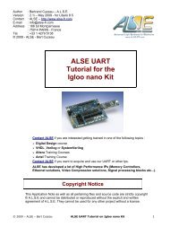
Illustration 1: Example of transmission of character 'A' in 7-E-2 format.<br />
As we can see, the physical format m<strong>and</strong>ates the use of an interface chip (<strong>RS232</strong> line driver aka “level<br />
shifter”) <strong>to</strong> transform the usual TTL (or lower) logic signals in<strong>to</strong> positive <strong>and</strong> negative voltages, <strong>and</strong> vice<br />
versa. These chips now do not even require a negative power supply, only one <strong>to</strong> four external capaci<strong>to</strong>rs<br />
since they include a charge pump system <strong>to</strong> generate the stepped up <strong>and</strong> negative voltages.<br />
If you look at the <strong>RS232</strong> signal on the transmission line, you'll notice that a logic “1” at the logic side<br />
corresponds <strong>to</strong> -10V <strong>and</strong> a logic “0” <strong>to</strong> +10V ; there is an “inversion”. For his<strong>to</strong>rical reasons, the two levels<br />
may be referred <strong>to</strong> as “mark” for logic 0 <strong>and</strong> “space” for logic 1.<br />
A consequence of the format is that it is very easy <strong>to</strong> determine if a signal on an <strong>RS232</strong> connec<strong>to</strong>r is an<br />
input or an output : an Idle output is quite negative, while an input is typically in the indeterminate region.<br />
To transform parallel characters of the expected lengths in a serial stream <strong>and</strong> back, “<strong>UART</strong>” chips were<br />
typically used (Universal Asynchronous Receive-Transmit). We'll see you can easily design your own.<br />
Important ! For a local (short range) transmission : chip <strong>to</strong> chip, or FPGA <strong>to</strong> Micro-Controller etc, you do<br />
not have <strong>to</strong> convert <strong>to</strong> the high level voltages ! It is perfect just <strong>to</strong> stay at the logic levels.<br />
In fact, level converters are only qualified <strong>to</strong> maximum bit rates that may not be <strong>to</strong>o high. The best ones<br />
are typically qualified at 230k bauds maximum. Without level converters, you can reach higher speeds.<br />
Note that, even if you use <strong>RS232</strong> level shifters, you may just ignore the symmetrical voltages <strong>and</strong> only<br />
think of 0's <strong>and</strong> 1's in the logic level side, as we do in the rest of this document.<br />
© 2009 A.L.S.E. - B. Cuzeau ApNote: <strong>RS232</strong> Basics 3
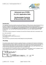
Timing Diagram – logic level side<br />
Note :<br />
We are now observing the signals at the <strong>UART</strong>/FPGA side, not at the +/- 15V physical line (in other<br />
words, we look at the FPGA or <strong>UART</strong> side of the line level converter if one is used).<br />
When transmitting a character :<br />
➢<br />
➢<br />
➢<br />
➢<br />
a START BIT (0) is first sent,<br />
followed by the DATA bits (general 8, but could be 5, 6, 7, or 8 bits),<br />
starting with the LSB <strong>and</strong> continuing up <strong>to</strong> the MSBit,<br />
followed by a PARITY bit (if parity is enabled),<br />
followed by a STOP bit (1) which duration can be 1, 1.5 or 2 bit lengths.<br />
The duration of each bit is equal <strong>to</strong> (1 sec / Baud_Rate).<br />
The sequence is repeated for each character sent, but the line may remain Idle (=1) for any duration.<br />
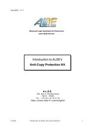
<strong>RS232</strong> Character Transmission<br />
Logic Levels, 8 Bits, Parity<br />
(c) 2008 - <strong>ALSE</strong><br />
1<br />
Line is Idle<br />
0<br />
Start<br />
D0 D1 D2 D3 D4 D5 D6 D7 Par<br />
S<strong>to</strong>p<br />
Line is Idle<br />
Example : String « A2 » @ N81, no delay between chars<br />
Line is Idle<br />
Line is Idle<br />
Start<br />
S<strong>to</strong>p<br />
Start<br />
S<strong>to</strong>p<br />
1 0 0 0 0 0 1 0<br />
0 1 0 0 1 1 0 0<br />
Character « A » = 41hex = 01000001<br />
Character « 2 » = 32hex = 00110010<br />
Illustration 2: <strong>RS232</strong> Timing Diagram – Logic Levels<br />
Actual transmission speed<br />
From the above diagram, it is easy <strong>to</strong> deduce that the maximum effective transmission speed, in the case<br />
of NO PARITY <strong>and</strong> EIGHT BITS per character is : Baud Rate / 10.<br />
At 115,200 bauds, the maximum transfer rate is 11,520 bytes per second.<br />
© 2009 A.L.S.E. - B. Cuzeau ApNote: <strong>RS232</strong> Basics 4
Designing an <strong>RS232</strong> Transmitter<br />
This is the “piece of cake” part ! Let take the example of 115200 N 8 1 format.<br />
- Build a timer generating ticks at the (as exact as possible) baud rate (= 8.6805555... us).<br />
- Build a 9 bits shift register with right-most bit connected <strong>to</strong> the TX output, <strong>and</strong> initialized <strong>to</strong> all 1's.<br />
1. To transmit a new character “Byte” : upon a tick, load the shift register with “Byte-0”.<br />
2. Shift right ten times at each tick, shifting in a “1” from the left.<br />
3. When done shifting, you're ready <strong>to</strong> send another character.<br />
Slick. Designing the transmitter is typically a 15 minutes task in HDL, including verification.<br />
Even with the few steps involved, it's still a very good idea <strong>to</strong> implement the Transmitter using a Finite<br />
State Machine (<strong>and</strong> a counter variable <strong>to</strong> count down from 10 <strong>to</strong> 0).<br />
Designing an <strong>RS232</strong> Receiver<br />
This is the (slightly) more difficult part. Let take again the example of 115200 N 8 1 format.<br />
You must have a tick genera<strong>to</strong>r that can be restarted on dem<strong>and</strong> <strong>and</strong> generating ticks at half the bit<br />
period. And a 9-bits Shift Register SR[8..0].<br />
1. Keep your Tick Genera<strong>to</strong>r at zero, waiting until the Rx line input goes low (beginning of Start bit).<br />
2. Loop 10 times :<br />
(a) Wait for tick (mid-bit), Right-Shift in the Data Line (Rx) in your register.<br />
(b) if reached last (s<strong>to</strong>p) bit then exit the loop, else just Wait Tick (end of bit).<br />
3. End of Loop : the register's MSB (SR[8]) must be “1” (s<strong>to</strong>p bit), else you have a problem (line may<br />
not be synchronized, incorrect baud rate or format etc...).<br />
The character is in SR[7:0], you can pass it <strong>to</strong> the next block (in charge of processing the<br />
characters), or push it in a Fifo, etc...<br />
Return <strong>to</strong> state 1.<br />
Obviously, this is very simple <strong>to</strong> implement as a Finite State Machine.<br />
Going further<br />
A NOTE TO STUDENTS: do not email me <strong>and</strong> ask for my <strong>UART</strong> ! Use the above document for help, <strong>and</strong><br />
do your homework. Designing your own simple <strong>UART</strong> just takes a few hours of efforts maximum, <strong>and</strong> you<br />
wouldn't <strong>learn</strong> anything by using mine.<br />
But if you are involved in a much more complex Educational Project <strong>and</strong> just need a <strong>UART</strong> as an auxiliary<br />
function, then you can contact me.<br />
<strong>ALSE</strong>'s website contains more information <strong>about</strong> <strong>how</strong> <strong>to</strong> implement a <strong>UART</strong>, the elements of a behavioral<br />
model, a sample application etc... Our Tornado FPGA board has two <strong>RS232</strong> ports with appropriate level<br />
shifters <strong>and</strong> can be used <strong>to</strong> quickly implement <strong>and</strong> test a <strong>UART</strong>.<br />
NEW : <strong>UART</strong> Demo Kit (free) for Actel Igloo nano.<br />
I hope you enjoyed this quick summary <strong>and</strong> you are now convinced<br />
that <strong>RS232</strong> is still a very simple <strong>and</strong> very efficient method <strong>to</strong> exchange<br />
data with an FPGA at speeds up <strong>to</strong> 1 M bits/s.<br />
Bertr<strong>and</strong> Cuzeau – CTO A.L.S.E<br />
Tel +33 (0)1 4279 5138 – info at alse-fr dot com<br />
© 2009 A.L.S.E. - B. Cuzeau ApNote: <strong>RS232</strong> Basics 5