
You also want an ePaper? Increase the reach of your titles
YUMPU automatically turns print PDFs into web optimized ePapers that Google loves.
T A B L E O F C O N T E N T S<br />
DEMCO BUTTERFLY<br />
V ALVES<br />
Features & Benefits<br />
DEMCO Butterfly Valves 2<br />
DEMCO Butterfly Valves:<br />
Styles And Accessories 4<br />
Product Specifications<br />
How to Order Valves 6<br />
Base Numbers and Weights 9<br />
Component Parts List 10<br />
Dimensional Data (Valves) 12<br />
How to Order (and Technical Information)<br />
Handles 15<br />
Worm Gear Operators 16<br />
DR Piston Actuators 18<br />
Diaphragm Actuators 22<br />
Stem Extensions, Tees and Adapters 23<br />
General Technical Information 24<br />
Standard Material Data 29<br />
Terms and Conditions 31<br />
Trademark Information 32
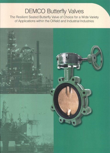
DEMCO DEMCO B U T T E R F L Y V A L V E S<br />
Acclaimed as the most durable of<br />
all resilient-seated <strong>butterfly</strong> <strong>valves</strong><br />
in the industry, this valve excels<br />
in a wide variety of applications.<br />
Cast in both wafer and tapped-lug patterns<br />
in a wide variety of material choices,<br />
DEMCO <strong>butterfly</strong> <strong>valves</strong> feature a onepiece<br />
body for minimum weight and<br />
maximum strength. The unique stem hole<br />
design in the disc ensures a dry stem journal,<br />
and the hard-backed seat (2" - 36")<br />
allows ease of installation, reliable operation,<br />
and is field-replaceable without special<br />
tools. DEMCO <strong>butterfly</strong> <strong>valves</strong> are<br />
available in sizes 2" thru 48".<br />
Engineered for long-term, maintenance-free<br />
performance, DEMCO <strong>butterfly</strong><br />
<strong>valves</strong> are <strong>com</strong>monly selected for a<br />
variety of applications spanning a wide<br />
range of industries:<br />
• Chemical and petrochemical<br />
• Agriculture<br />
• Oil and gas drilling and production<br />
• Food and beverage<br />
• Water and waste water<br />
• Cooling towers (HVAC)<br />
• Power<br />
• Mining and materials<br />
• Dry bulk handling<br />
• Marine and government<br />
Features/Benefits<br />
Bi-directional sealing<br />
This valve provides bi-directional sealing<br />
at full-rated pressure with identical flow<br />
from either direction.<br />
Integral flange seal<br />
Molded into the edge of the seat is an<br />
integral flange seal which ac<strong>com</strong>modates<br />
ANSI weld neck, slip-on, threaded and<br />
socket flanges as well as “stub end”<br />
type C flanges.<br />
ANSI class 150 rating<br />
Body rating is ANSI class 150 (285 psi<br />
non-shock). Wafer body diameters are<br />
Flatted “double D”upper stem<br />
Large flange top for ease of<br />
power automation (full line of<br />
actuation and accessories offered)<br />
Bronze bearings<br />
Positive stem retention for<br />
blowout proof stems<br />
MSS SP-25 marking is standard<br />
Triple stem seal<br />
Positively oriented disc<br />
High flow disc<br />
Hard backed<br />
cartridge seat<br />
(2" - 36")<br />
One piece body<br />
Wafer style shown<br />
p2<br />
F E A T U R E S A N D B E N E F I T S
DEMCO B U T T E R F L Y<br />
V A L V E S<br />
DEMCO<br />
designed to self-center in ANSI 150<br />
flange patterns.<br />
Multiple pressure ratings<br />
Three drop tight pressure ratings are<br />
offered for 2" to 12" sizes. The standard<br />
shut off pressure rating is 200 psi, but<br />
285 and 50 psi shut off ratings are also<br />
available. And, where drop tight closure<br />
is not required and minimal torque is<br />
desired, a throttling rated valve is available.<br />
Both the 50 psi and throttling ratings<br />
allow for smaller actuators, which<br />
can significantly reduce overall installation<br />
cost in automated applications. The<br />
Hard-backed seat<br />
A<br />
B<br />
14" to 48" size <strong>valves</strong> are available in 150<br />
and 50 psi drop tight shut off ratings as<br />
well as throttling.<br />
A Dry stem journal eliminates<br />
potential for leakage<br />
The DEMCO disc is uniquely designed<br />
with a continuous annular raised land<br />
around the stem hole and disc edge which<br />
presses into the seat flat at every angular<br />
position. The resilient seat presses back<br />
with a higher specific force than the line<br />
pressure, preventing leakage to the stem.<br />
In addition, two O-ring ribs are provided<br />
in the seat stem bore creating a triple<br />
stem seal.<br />
In <strong>com</strong>petitive stem seal designs<br />
with boot seats, a seal is ac<strong>com</strong>plished<br />
by an interference “squeezing” on the<br />
stem or an O-ring in the stem journal.<br />
The potential for leakage behind the<br />
seat is high for this <strong>com</strong>petitive design.<br />
As the disc wipes the seat, elongation of<br />
the stem seal area allows leakage to collect<br />
behind the seat. This condition is<br />
eliminated by DEMCO’s dry stem journal<br />
and hard-backed seat.<br />
B Hard-backed cartridge seat (2"- 36")<br />
The DEMCO cartridge seat is constructed<br />
by permanently bonding a resilient elastomer<br />
to a rigid backing ring. In addition<br />
to superior sealing integrity, this design:<br />
1) makes valve installation easier because<br />
no special precautions are required for<br />
disc position. This is especially advantageous<br />
when installing <strong>valves</strong> with fail<br />
closed actuators; 2) eliminates high<br />
torque and premature failure caused by<br />
elastomer distortion as found in other<br />
non-rigid seat designs; 3) simplifies seat<br />
replacement because it is slip fitted into<br />
the body, with no need for special tools.<br />
C Positively oriented disc<br />
Proper orientation of the stem/disc<br />
connection is assured by the rectangular<br />
drive. In 2" - 24" size <strong>valves</strong>, the disc is<br />
permitted to float on the stem to perfectly<br />
center in the valve seat. This design<br />
enhances drop tight sealing and prolongs<br />
service life.<br />
D End-of-line service<br />
Lug body <strong>valves</strong> may be used in end-ofline<br />
service, with downstream piping<br />
removed. (Only weld neck or socket<br />
flanges can be used for this service.)<br />
Since upstream pressure is excluded<br />
between the flange and the seat face by<br />
the exclusive DEMCO flange seal design,<br />
there is no effective force to slide the seat<br />
downstream. DEMCO 2" - 12" Lug<br />
Butterfly Valves are suitable for liquid<br />
service up to 200 psi with downstream<br />
piping removed (150 psi 14" - 36").<br />
Lug body <strong>valves</strong> are re<strong>com</strong>mended<br />
for isolation of pumps, control devices<br />
or other system <strong>com</strong>ponents which may<br />
need to be removed for repair or replacement.<br />
Lug <strong>valves</strong> are also suitable for<br />
installation at points from which piping<br />
expansion may proceed. Such <strong>valves</strong><br />
are normally blanked with blind flanges,<br />
to protect the exposed seats until new<br />
piping is attached.<br />
C<br />
D<br />
SPECIFICATIONS<br />
Sizes<br />
2" - 48"<br />
Body type and style designations<br />
Long neck NE-C and NF-C: 2" - 48",<br />
2" - 36"wafer / lug, 42" - 48" flanged.<br />
Short neck NE-I, and NE-I Sanitary:<br />
2" - 12" wafer / lug.<br />
NE-IT Teflon: 2" - 10" wafer / lug.<br />
NE-D: 2" - 12" wafer / lug.<br />
Marine: 2" - 24" wafer / lug.<br />
Pressure rating<br />
2" - 12": 0 (Throttling), 50, 200 and 285 psi<br />
2" - 10" NEI-T: 150 psi<br />
14" - 48" 0, 50 and 150 psi<br />
Operating Temperatures<br />
-30ºF to +300ºF (-34ºC to +204ºC)<br />
depending on seat material selection<br />
and application (see page 30)<br />
Standard Material Options<br />
Bodies: Iron, steel, stainless steel and<br />
bronze<br />
Discs: Nickel plated ductile iron, bronze<br />
and stainless steel<br />
Stems: 416 and 316 stainless steel<br />
Seats: Buna N, EPT, Viton, Neoprene<br />
*Many more options available (see how<br />
to order, pages 6-8 and 29-30 or consult<br />
factory)<br />
F E A T U R E S A N D B E N E F I T S<br />
p3
DEMCO S T Y L E S A N D A C C E S S O R I E S<br />
This versatile valve <strong>com</strong>es in a<br />
variety of styles to suit an even<br />
wider range of applications. In<br />
addition, a variety of quality<br />
accessories are available to<br />
further enhance its suitability<br />
to the application.<br />
A Series NE-C<br />
Sizes 2" to 12", this series is a general<br />
purpose valve with neck length designed<br />
to provide full clearance of the valve top<br />
over two inches of insulation on ANSI<br />
150 pipe flanges; available in both wafer<br />
and lug styles.<br />
B Series NE-I<br />
Sizes 2" to 12", it is suited for a wide<br />
range of applications in many industries,<br />
including food and beverage utilities and<br />
process flow lines. This short neck design<br />
is offered in a wide variety of body materials.<br />
The <strong>valves</strong> are designed for installation<br />
between ANSI 125/150 flanges.<br />
system gives absolute assurance of sanitary<br />
<strong>butterfly</strong> valve construction.<br />
• Drilled passageways, a design originated<br />
by DEMCO, vent the entire interior<br />
of the disc to atmosphere. No closed<br />
chamber is provided for the culture of<br />
undesirable organisms.<br />
• Discs are produced from investment<br />
castings, smooth and non-porous. Stem<br />
bosses are minimized for increased flow.<br />
• The projecting inner surface of the<br />
resilient seat contacts and is <strong>com</strong>pressed<br />
by the mating flange to form a smooth<br />
and uninterrupted flow way. This positive<br />
seal between the innermost contact of the<br />
seat and flange ensure aseptic conditions<br />
after a piping flush.<br />
Sanitary Features<br />
A<br />
B<br />
C Series NE-D Valve<br />
Sizes 2" to 12", it is a short neck valve<br />
with body notches to fit popular lightweight<br />
flange patterns, making it ideal for<br />
bulk material handling and the transportation<br />
industry. Valves will also center in<br />
ANSI 125/150 flanges.<br />
D Series NF-C (14" - 48")<br />
Sizes 14" to 36" are available in both<br />
wafer and lug styles. The wafer body has<br />
two drilled locator lugs at top and bottom<br />
for ANSI 150 flanges. 42" and 48" sizes<br />
are available with flanged bodies. On all<br />
sizes, bronze bearings are installed on<br />
both stems for minimum operating torque.<br />
Series NE-I Sanitary<br />
Sizes 2" - 12", it is similar to our Series<br />
NE-I valve, but is exclusively designed to<br />
meet the rigorous requirements of sanitary<br />
service in the food and beverage<br />
industry. The body is available in bronze,<br />
stainless steel, aluminum or electroless<br />
nickel-coated ductile iron. FDA -<br />
approved materials are used for all wetted<br />
parts. Handle parts are bronze and stainless<br />
steel, permitting caustic washdown.<br />
Other benefits:<br />
• DEMCO dry journal stem seal<br />
Series NEI-T Teflon<br />
Because of the inert, aseptic non-stick<br />
character of Teflon, DEMCO’s NEI-T<br />
Teflon-lined <strong>butterfly</strong> valve is ideal for<br />
“clean” lines in food and beverage plants.<br />
The Teflon seat consists of a virgin Teflon<br />
liner overlaying and bonded to an elastomer<br />
cushion (either Buna-N or EPT are<br />
available) which provides resilience for<br />
sealing. The Teflon liner extends over the<br />
seat faces, <strong>com</strong>pletely covering and sealing<br />
the resilient material from contact<br />
with line fluids.<br />
Marine<br />
DEMCO Marine <strong>butterfly</strong> <strong>valves</strong> are<br />
available in the NE-C Lug, NE-I Lug and<br />
Wafer and NE-D Wafer styles and conform<br />
to Title 46 of the Code of Federal<br />
Regulations, Part 56 of the U.S. Coast<br />
Guard’s Marine Engineering Regulations<br />
as well as the American Bureau of<br />
Shipping Standard including tagging per<br />
MSS-SP-25 and testing per MSS-SP-67.<br />
Series NF-C 16"<br />
Series NF-C 30"<br />
C<br />
D<br />
D<br />
p4<br />
F E A T U R E S A N D B E N E F I T S
S T Y L E S A N D A C C E S S O R I E S<br />
DEMCO<br />
DEMCO NE-C wafer with<br />
Series DR actuator.<br />
A2<br />
A1<br />
Series R diaphragm actuator<br />
B<br />
Stem extension<br />
with handle<br />
on Series NE-I<br />
<strong>butterfly</strong> valve<br />
A Actuators<br />
DEMCO Series DR pneumatic actuators<br />
(A1) are available in double-acting or<br />
fail-safe, spring return models. Series DR<br />
actuators are <strong>com</strong>pact, high-torque, piston<br />
actuators. Series R diaphragm actuators<br />
(A2) incorporate a heavy-duty, enclosed<br />
rack-and-pinion linkage. Diaphragm actuators<br />
are suitable for low-pressure, pneumatic<br />
service. Electric actuators (A3) are<br />
used when <strong>com</strong>pressed air is not available<br />
for pneumatic operations.<br />
B Handles and stem extensions<br />
Three basic handle designs interchange<br />
on any 2" to 12" <strong>valves</strong>: ten position<br />
locking, two position locking and memory<br />
stop. Memory-stop handles provide<br />
throttling which is infinitely adjustable<br />
and can be set by a lock nut with memory-stop<br />
setting (adjustable open stop).<br />
Handles are available in basic trim, corrosion-resistant<br />
trim and sanitary trim. Stem<br />
extensions are fabricated from carbon<br />
steel parts and contained in a tubular<br />
housing. Gaskets and O-rings seal the<br />
stem extension at top and bottom. These<br />
extensions are fabricated to specified<br />
lengths.<br />
C Gear operators<br />
DEMCO weatherproof gear operators are<br />
offered with a choice of handwheel,<br />
chain-wheel, or square nut. The worm<br />
gearing has self-locking set screws to<br />
control open and closed positioning or<br />
an optional adjustable memory stop for<br />
“balance return” to a preset open<br />
position after closing.<br />
A3<br />
Electric actuator<br />
C<br />
Gear operator<br />
F E A T U R E S A N D B E N E F I T S<br />
p5
DEMCO S E R I E S NE-C, NE-I, NE-D, NEI-T, 2"–12"<br />
Parts<br />
Detail<br />
Ref.<br />
Req’d Component Material<br />
No. Description<br />
1 1 Body *<br />
2 1 Seat *<br />
3 1 Disc *<br />
4 1 Upper Stem *<br />
6 1 Lower Stem *<br />
7 2 Spring Pin Stainless Steel<br />
14 1 Retainer Stainless Steel<br />
22 1 Top O-Ring Buna-N<br />
23 † Stem O-Ring Buna-N<br />
24 2 Bearing Bronze<br />
*See How to Order for material choices/styles.<br />
Complete material specs on pages 29 and 30.<br />
†4 req’d. for throttling <strong>valves</strong> only.<br />
How to Order (example: 6" NE-C, 200PSI, Wafer, Standard trim with handle 22124-1215311)<br />
X X X X X – X X X X X X<br />
Base Part Body Body Stem Disc Seat Actuation<br />
Number Configuration Material* Material Material Elastomer<br />
NE-C/NE-I/NEI-T<br />
Wafer 1<br />
Lug 5<br />
NE-D<br />
Wafer 1<br />
Based on<br />
valve series<br />
and shut off<br />
pressure.<br />
See page 9.<br />
NE-C (Longneck)<br />
Ductile Iron (lug) 1<br />
Cast Iron (wafer) 2<br />
NE-I & NE-I Sanitary<br />
Ductile Iron<br />
1<br />
(NE-I, wafer only)<br />
Aluminum Bronze 3<br />
Carbon Steel<br />
(NE-I only)<br />
4<br />
Aluminum<br />
(NE-I, wafer only)<br />
5<br />
ENC Coated<br />
Ductile Iron<br />
6<br />
Stainless Steel 8<br />
NE-D<br />
Ductile Iron 1<br />
NEI-T<br />
Ductile Iron<br />
Wafer–Shortneck 1<br />
Lug–Longneck<br />
Gray Iron<br />
2<br />
(longneck wafer)<br />
Aluminum Bronze 3<br />
Carbon Steel 4<br />
Aluminum<br />
(wafer only)<br />
5<br />
Stainless Steel 8<br />
NE-C, NE-I<br />
& NE-D<br />
416 SS 1<br />
316 SS** 2<br />
Monel (6) 3<br />
NEI-T<br />
316 SS<br />
Vented***<br />
2<br />
316 SS<br />
Solid***<br />
9<br />
NE-I Sanitary<br />
316 SS** 2<br />
**Standard coating is green enamel; other coatings available on request.<br />
**17-4 PH SS for 8"-12" upper stem only.<br />
***Except 17-4 PH upper 8" & 10".<br />
1. 200 psi only.<br />
2. Except 285 psi.<br />
3. Polished–ground to # 4 dairy finish, Tumbled–vibratory finish to remove<br />
“as cast” surface, Unpolished–“as cast” surface<br />
NE-C, NE-I<br />
& NE-D<br />
316 SS 2<br />
Monel (6) 3<br />
Aluminum<br />
Bronze<br />
4<br />
Ductile Iron<br />
Nickel Plated 5<br />
PVF Coated<br />
Ductile Iron (1) 6<br />
Alloy 20 (2) 7<br />
Hastelloy “C” (6) 8<br />
NEI-T &<br />
NE-I Sanitary<br />
316 SS/<br />
PVF Coated 0<br />
(NEI-T only)<br />
316 SS<br />
2<br />
Polished (3)<br />
316 SS<br />
5<br />
Tumbled (3)<br />
Alloy 20<br />
7<br />
(NEI-T only)<br />
Hastelloy “C”<br />
(NEI-T only)<br />
8<br />
316 SS<br />
Unpolished (3) 9<br />
NE-C, NE-I & NE-D (7)<br />
Buna-N 31<br />
Black Neoprene 32<br />
Hypalon (6) 33<br />
Viton (6) 34<br />
Peroxide Cured EPT 35<br />
Natural Rubber 36<br />
White Neoprene 37<br />
ETM-30230 01<br />
Fluorosteam 02<br />
Peroxide Cured<br />
Food Grade EPT<br />
03<br />
Peroxide Cured<br />
Buna-N 04<br />
Sulfur Cured<br />
Food Grade EPT<br />
05<br />
NEI-T<br />
Buna-N/Teflon (6) 31<br />
Peroxide Cured<br />
EPT/Teflon (6) 35<br />
Sulfur Cured<br />
EPT/Teflon (6)<br />
05<br />
NE-I Sanitary<br />
All Seats Food Grade<br />
Buna-N 31<br />
Black Neoprene 32<br />
Viton 34<br />
EPT 35<br />
White Neoprene 37<br />
Sulfur Cured EPT 05<br />
Handle<br />
10 Position Lkg. 1 (4)<br />
Throttling<br />
2<br />
Mem./Stop<br />
(4)<br />
Square Nut 5<br />
2 Position Lkg. 6 (4)<br />
10 Position<br />
Sanitary 8<br />
(NEI-T only)<br />
None 9<br />
10 Position Lkg.<br />
Corrosion K<br />
resistant<br />
2 Position Lkg.<br />
Corrosion L<br />
resistant<br />
Throttling/<br />
Mem. stop<br />
M<br />
Corrosion<br />
resistant<br />
Gear Operators (5)<br />
Hand Wheel A<br />
Crank<br />
(2"-12" only) B<br />
Chain Wheel C<br />
Square Nut D<br />
Bare Shaft E<br />
4. When these options used with NE-I Sanitary <strong>butterfly</strong> <strong>valves</strong>,<br />
handles will be bronze with SS parts and fasteners.<br />
5. Gear operator re<strong>com</strong>mended for 8"-12" sizes in all series.<br />
6. See material trademark note on page 32.<br />
7. Other seat options available (consult factory).<br />
p6<br />
P R O D U C T S P E C I F I C A T I O N S
S E R I E S NF-C, 14"–24"<br />
DEMCO<br />
Parts Detail<br />
Ref.<br />
No.<br />
Req’d<br />
Component<br />
Description<br />
Material<br />
1 1 Body *<br />
2 1 Seat *<br />
3 1 Disc *<br />
4 1 Upper Stem *<br />
6 1 Lower Stem *<br />
7 2 Spring Pin Stainless Steel<br />
14 1 Retainer (Spacer)‡ Steel<br />
23 † Stem O-Ring Buna-N<br />
24 2 Upper Bearing Bronze<br />
25 1 Lower Bearing Bronze<br />
*See How To Order for material choices/styles. Complete material specs<br />
on pages 28 and 29.<br />
†4 Req’d. for throttling <strong>valves</strong> only.<br />
‡14"–20" Retainer, 24" Spacer.<br />
How to Order (example: 18" NF-C, 150PSI LUG, SS trim, Buna-N seat, WGO. 23822-512231A)<br />
X X X X X – X X X X X X<br />
Base Part Body Body Stem Disc Seat<br />
Number Configuration Material* Material Material Elastomer<br />
Actuation<br />
Wafer 1<br />
Lug 5<br />
Based on<br />
shut off<br />
pressure.<br />
See page 9.<br />
Ductile Iron (lug) 1<br />
Cast Iron (wafer) 2<br />
Steel (lug) 4<br />
Stainless Steel (lug) 8<br />
416 SS 1<br />
316 SS 2<br />
Monel (2) 3<br />
316 SS 2 Buna-N 31<br />
Monel (2) 3 Black Neoprene 32<br />
Aluminum<br />
Hypalon<br />
4<br />
(2) 33<br />
Bronze<br />
Viton (2) 34<br />
Nickel Plated<br />
5<br />
EPT 35<br />
Iron<br />
PVF Coated<br />
6<br />
Ductile Iron (1)<br />
None 9<br />
Gear Operators<br />
Hand Wheel A<br />
Chain Wheel C<br />
Square Nut D<br />
Bare Shaft E<br />
*Standard coating is green enamel; other coatings available on request.<br />
(1)150 psi only.<br />
(2)See material trademark note on page 32.<br />
P R O D U C T S P E C I F I C A T I O N S<br />
p7
DEMCO S E R I E S NF-C, 30"–48"<br />
Parts Detail<br />
Ref.<br />
No.<br />
Req’d<br />
Component<br />
Description<br />
Material<br />
1 1 Body *<br />
Seat –Hard-Backed<br />
2 1<br />
30"- 36"<br />
Seat – Elastomer Liner<br />
42"-48"<br />
*<br />
3 1 Disc–150 psi *<br />
4 1 Upper Stem *<br />
6 1 Lower Stem *<br />
7 2 Disc Screw 18-8 SS<br />
8 1 Key Stainless Steel<br />
9 2 O-Ring Buna-N<br />
14 1 Spacer Steel<br />
24 2 Upper Bearing Bronze<br />
25 1 Lower Bearing Bronze<br />
26 1 Thrust Collar Bronze<br />
27 1 Set Screw 18-8 SS<br />
28 1 Cap<br />
Duct Iron 30"-36"<br />
Cast Iron 42"- 48"<br />
29 4 Screw Carbon Steel<br />
30 4 Lockwasher Carbon Steel<br />
*See How to Order for material choices/styles.<br />
Complete material specifications on page 28 and 29.<br />
How to Order (Example: 42", 150 psi, bronze disc, EPT seat with Gear Op 24106-621435A)<br />
X X X X X – X X X X X X<br />
Base Part Body Body Stem Disc Seat Gear<br />
Number Configuration Material* Material Material Elastomer Operators<br />
Wafer 1<br />
Lug 5<br />
Flange 6<br />
42"& 48"<br />
See page 9<br />
Ductile Iron 1<br />
(Wafer or lug)<br />
Cast Iron 2<br />
(Flanged only)<br />
416 SS 1<br />
316 SS 2<br />
Monel‡ 3<br />
316 SS 2 Buna-N 31<br />
Monel‡ 3 Black Neoprene 32<br />
Aluminum<br />
Hypalon‡ 33<br />
4<br />
Bronze<br />
Viton‡ 34<br />
Ductile Iron<br />
Nickel Plated 5 EPT 35<br />
Hand Wheel<br />
Chain Wheel<br />
Square Nut<br />
Bare Stem<br />
A<br />
C<br />
D<br />
E<br />
‡See material trademark note on page 32.<br />
**Standard coating is green enamel;<br />
other coatings available on request.<br />
p8<br />
P R O D U C T S P E C I F I C A T I O N S
B U T T E R F L Y<br />
V A L V E S<br />
DEMCO<br />
Base Part Numbers/Weights<br />
Series NE-C, 2"–12"*<br />
Description 2" 2½" 3" 4" 5" 6" 8" 10" 12"<br />
200 psi 22119 22120 22121 22122 22123 22124 22125 22126 22127<br />
285 psi 22225 22226 22227 22228 22229 22230 22231 22232 22233<br />
50 psi 22234 22235 22236 22237 22238 22239 22240 22241 22242<br />
Throttling 22243 22244 22245 22246 22247 22248 22249 22250 22251<br />
Weight Wafer 5.8 7.0 7.7 11.4 14.7 17.6 28.5 47.9 71.0<br />
(lbs–bare stem) Lug 8.0 9.9 10.7 17.0 24.5 28.5 43.5 65.9 98.5<br />
Series NE-I, 2"–12"*<br />
Description 2" 2½" 3" 4" 5" 6" 8" 10" 12<br />
200 psi 22128 22129 22130 22131 22132 22133 22134 22135 22136<br />
285 psi 22252 22253 22254 22255 22256 22257 22258 22259 22260<br />
50 psi 22261 22262 22263 22264 22265 22266 22267 22268 22269<br />
Throttling 22270 22271 22272 22273 22274 22275 22276 22277 22278<br />
Weight Iron, Steel, SS 4.9 6.4 6.9 10.2 13.7 16.4 28.4 44.8 66.8<br />
(lbs–bare stem) Bronze 4.7 6.2 6.7 9.9 13.4 16.0 28.0 44.3 66.3<br />
Wafer<br />
Aluminum 2.8 3.4 4.1 5.9 8.7 10.8 18.2 30.4 47.2<br />
Weight Bronze 6.8 8.7 9.5 15.7 23.1 27.0 42.0 64.4 96.8<br />
(lbs–bare stem)<br />
Lug Steel, SS 7.0 8.9 9.7 16.0 23.5 27.5 42.5 64.9 97.5<br />
Series NE-I, Sanitary, 2"–12"*<br />
Description 2" 2½" 3" 4" 6" 8" 10" 12"<br />
200 psi 23150 23151 23152 23153 23154 23155 23156 23157<br />
Weights See chart above, NE-I, 2"–12"<br />
Series NE-D, 2"–12"*<br />
Description 2" 2½" 3" 4" 5" 6" 8" 10" 12"<br />
200 psi 22181 22129 25093 22183 22184 22185 22134 22186 22136<br />
285 psi 22279 22253 on application 22281 22282 22283 22258 22284 22260<br />
50 psi 22285 22262 on application 22287 22288 22289 22267 22290 22269<br />
Throttling 22291 22271 on application 22293 22294 22295 22276 22296 22278<br />
Weight<br />
(lbs-bare stem) Wafer 4.9 6.4 6.9 10.2 13.7 16.4 28.4 44.8 66.8<br />
Series NEI-T, 2"–10"*<br />
Description 2" 2½" 3" 4" 6" 8" 10"<br />
150 psi 24680 24681 24682 24683 24684 24685 24686<br />
Weight Iron, Steel, SS 4.9 6.4 6.9 10.2 16.4 28.4 44.8<br />
(lbs-bare stem) Bronze 4.7 6.2 6.7 9.9 16.0 28.0 44.3<br />
Wafer †<br />
Aluminum 2.8 3.4 4.1 5.9 10.8 18.2 30.4<br />
Weight Bronze 6.8 8.7 9.5 15.7 27.0 42.0 64.4<br />
(lbs-bare stem)<br />
Lug † Steel, SS 7.0 8.9 9.7 16.0 27.5 42.5 64.9<br />
*Gear Operator re<strong>com</strong>mended for 8"–12" sizes.<br />
†See NE-C chart above for weights of Long Neck Wafer and Lug <strong>valves</strong>.<br />
Series NF-C, 14"–24"<br />
Description 14" 16" 18" 20" 24"<br />
150 psi 23820 23821 23822 23823 23824<br />
50 psi 24440 24441 24442 24443 24444<br />
Throttling 24445 24446 24447 24448 24449<br />
Weight Wafer 102 166 214 257 401<br />
(lbs–bare stem) Lug 116 203 239 332 535<br />
Series NF-C, 30"–48"<br />
Description 30" 36" 42" 48"<br />
150 psi 24141 24357 24106 24832<br />
50 psi 24924 25061 - -<br />
Weights C/F C/F C/F C/F<br />
C/F = Consult Factory.<br />
Marine Valves: Consult factory for data sheets B-255, B-256 and B-258.<br />
P R O D U C T S P E C I F I C A T I O N S<br />
p9
DEMCO B U T T E R F L Y V A L V E S<br />
DEMCO Butterfly Valve Component Parts List: Series NE-C, NE-I, NE-D<br />
Parts List for Series NE-C, NE-I, and NE-D (replacement parts for NE, NE-S, and NE-N, consult factory or <strong>com</strong>pany representative)<br />
Ref<br />
#<br />
Component Description 2" 2 1 /2" 3" 4" 5" 6" 8" 10" 12"<br />
1 Body NE-C Wafer 22137-012 22138-012 22139-012 22140-012 22141-012 22142-012 22143-012 22144-012 22145-012<br />
ASTM A48 Gray Iron -012<br />
NE-C Lug 21986-05x 21987-05x 21988-05x 21989-05x 21990-05x 21991-05x 21992-05x 21993-051 21994-051<br />
Options ASTM A395 Ductile Iron -051, ASTM A48 Gray Iron -052<br />
NE-I Wafer 22681-01x 22681-02x 22681-03x 22681-04x 22681-05x 22681-06x 22681-07x 22688-01x 22689-01x<br />
Options ASTM A395 Ductile Iron -011, ASTM B148 Al. Bronze -013, ASTM A216 WCB Steel -014,<br />
ASTM B179 Aluminum -015, DI/ENC -016, ASTM A351 SS -018<br />
NE-I Lug 22695-05x 22696-05x 22697-05x 22698-05x 22699-05x 22700-05x 22701-05x 22702-05x 22703-05x<br />
Options ASTM B148 Al. Bronze -053, ASTM A216 WCB Steel -054, ASTM A351 SS -058<br />
NE-D Wafer 22187-021 22682-011 20594-021 22189-021 22190-021 22191-021 22687-011 22192-021 22689-011<br />
Options ASTM A395 Ductile Iron -0x1<br />
2 SEAT 1786-xxx 1788-xxx 1790-xxx 6 1792-xxx 1794-xxx 1002-xxx 1798-xxx 1815-xxx 1817-xxx<br />
Options -031 Buna-N, -032 Black Neoprene, -033 Hypalon, -034 Viton, -135 EPT 1 , -036 Nat. Rubber<br />
3" NE-D Seat (see below 6 ) -037 White Neoprene, -231 Peroxide Cured Buna-N, -244 Fluorosteam, -331 ETM-30230<br />
3 DISC 200 psi 22045-0xx 22046-0xx 22047-0xx 22048-0xx 22049-0xx 22050-0xx 22051-0xx 22052-0xx 22053-0xx<br />
285 psi 22196-0xx 22197-0xx 22198-0xx 22199-0xx 22200-0xx 22201-0xx 22202-0xx 22203-0xx 22204-0xx<br />
50 psi 22205-0xx 22206-0xx 22207-0xx 22208-0xx 22209-0xx 22210-0xx 22211-0xx 22212-0xx 22213-0xx<br />
Throttling 22214-0xx 22215-0xx 22216-0xx 22217-0xx 22218-0xx 22219-0xx 22220-0xx 22221-0xx 22222-0xx<br />
Options -002 316 SS, -003 Monel, -005 Ni. Pltd. Duct Iron, -007 Alloy 20 2 , -008 Hastelloy C, -014 Alum. Bronze 3<br />
PVF Coated 200 psi 22714-001 22715-001 22716-001 22717-001 22718-001 22719-001 22720-001 22721-001 22722-001<br />
4 UPPER STEM NE-C 22066-00x 22067-00x 22068-00x 22069-00x 22070-00x 22071-00x 22072-00x<br />
NE-I 22073-00x 22074-00x 22075-00x 22076-00x 22077-00x 22078-00x 22079-00x<br />
NE-D 22073-00x 22074-00x 22193-00x 22194-00x 22195-00x 22077-00x 22078-00x 22079-00x<br />
UPPER STEM NE-C 22334-00x 22335-00x 22336-00x 22337-00x 22338-00x 22339-00x 22340-00x<br />
-Utility Top NE-I 22341-00x 22342-00x 22343-00x 22344-00x 22345-00x 22346-00x 22347-00x<br />
6 LOWER STEM 22080-00x 22081-00x 22082-00x 22083-00x 22084-00x 22085-00x 22086-00x<br />
Stem Material Options -001 416 SS, -002 316 SS 4 , -003 Monel, -004 Phos. Coated Steel<br />
7 SPRING PIN (2) 302 SS 5448-18720 5448-18724 5448-25028<br />
14 RETAINER Stainless Steel 22117 13704 13705 13706 13707<br />
22 TOP O-RING Buna-N 5526-114 5526-115 5526-117 5526-119 5526-125<br />
23 STEM O-RING 5 Buna-N 5526-113 5526-115 5526-116 5526-212 5526-214 5526-220<br />
24 BEARING (2) Bronze 22526-001 22118-001 13112-001 13115-001 13116-001 13117-001<br />
1 EPT Seat Options: Standard -135 Peroxide Cured, Food Grade -035<br />
Peroxide Cured, -235 Sulfur Cured.<br />
2 Alloy 20 not available for 285 psi.<br />
3 8” - 12”, 285 psi Alum. Bronze, use “-024”.<br />
4 8” - 12”, Upper Stem 17-4 PH SS (p/n suffix -012), Lower Stem 316SS.<br />
5 4 required for throttling (0 psi) <strong>valves</strong> only.<br />
6 3" NE-D Seat PN. 25095-xxx.<br />
p10<br />
P R O D U C T S P E C I F I C A T I O N S
B U T T E R F L Y<br />
V A L V E S<br />
DEMCO<br />
DEMCO Butterfly Valve Component Parts List: Series NF-C<br />
Parts List for Series NF-C<br />
Index Req’d Description 14" 16" 18" 20" 24" Material<br />
1 1 Body<br />
-031 Buna-N -032 Blk. Neoprene<br />
Lug 23827-051 23911-051 23901-051 23891-051 23875-051 -051 Ductile Iron (Lug)<br />
Wafer 23825-012 23907-012 23899-012 23881-012 23873-012 -012 Cast Iron (Wafer)<br />
2 1 Seat 23829-03x 23913-03x 23903-03x 23893-03x 7103-03x -033 Hypalon -034 Viton<br />
-X35 EPT 3<br />
Disc -150 psi 23830-0xx 23915-0xx 23905-0xx 23895-0xx 23877-0xx -002 316 SS -003 Monel<br />
3 1<br />
-50 psi 24450-0xx 24451-0xx 24452-0xx 24453-0xx 24454-0xx -014 Al. Brz.<br />
-Throttling 24455-0xx 24456-0xx 24457-0xx 24458-0xx 24459-0xx -005 Ni. Pltd. Iron<br />
-PVF CTD. 24460-001 24461-001 24462-001 24463-001 24464-001 -001 PVF CTD Iron<br />
4 1 Upper Stem 23833-00x 23917-00x 23897-00x 23897-00x 23879-00x -001 416 SS, -002 316 SS<br />
6 1 Lower Stem 23834-00x 23918-00x 23898-00x 23898-00x 23880-00x -003 Monel, -004 Steel<br />
7 2 Spring Pin 5446-25040 5446-250405446-25048 5446-25048 5446-25064 Stainless Steel<br />
14 1 Retainer (Spacer) 2 5502-137 5502-150 5502-175 5502-175 24470 Steel<br />
23 Note 1 Disc O-Ring 5526-220 5526-223 5526-328 5526-328 5526-331 Buna-N<br />
24 2 Upper Bearing 5086-004 5086-050 5086-048 5086-048 5086-046 Bronze<br />
25 1 Lower Bearing 5086-045 5086-051 5086-049 5086-049 5086-047 Bronze<br />
1 4 Req’d., throttling <strong>valves</strong> only.<br />
2 14” - 20” Retainer, 24” Spacer.<br />
3 EPT Seat Options: Standard -135 Peroxide Cured, Food Grade -035<br />
Peroxide Cured, -235 Sulfur Cured.<br />
P R O D U C T S P E C I F I C A T I O N S<br />
p11
DEMCO B U T T E R F L Y V A L V E S<br />
Series NE-C, 2"–12"<br />
Dimensional Data (inches)<br />
Size A C D E F G H J K L N P R S<br />
2" 1.74 5.62 8.44 4.12 4.00 3.25 .408 4.75 5/8-11 4 1.00 .44 .625 .375<br />
2½" 1.86 6.12 9.19 4.88 4.00 3.25 .408 5.50 5/8-11 4 1.00 .44 .625 .375<br />
3" 1.86 6.38 9.69 5.38 4.00 3.25 .408 6.00 5/8-11 4 1.00 .44 .625 .375<br />
4" 2.11 7.12 11.00 6.88 4.00 3.25 .408 7.50 5/8-11 8 1.00 .44 .625 .375<br />
5" 2.24 7.75 12.12 7.75 4.00 3.25 .408 8.50 3/4-10 8 1.25 .44 .838 .500<br />
6" 2.24 8.25 13.25 8.75 4.00 3.25 .408 9.50 3/4-10 8 1.25 .44 .838 .500<br />
8" 2.54 9.44 15.56 11.00 6.00 5.0 .533 11.75 3/4-10 8 1.38 .56 .838 .500<br />
10" 2.74 11.25 18.69 13.38 6.00 5.0 .533 14.25 7/8-9 12 1.38 .56 .963 .625<br />
12" 3.24 12.19 21.69 16.12 6.00 5.0 .533 17.00 7/8-9 12 1.38 .56 1.338 .750<br />
Note: For general dimensions, see page 26.<br />
Series NF-C, 14"–24"<br />
Dimensional Data (inches)<br />
Size A B C D E G H J K L M N P R S T U<br />
14" 3.00 10.63 12.75 23.4<br />
16" 4.00 11.66 13.75 25.4<br />
18" 4.50 12.96 14.75 27.7<br />
20" 5.00 13.97 15.75 29.7<br />
24" 6.00 16.19 19.00 35.2<br />
*Wafer valve dimension is the bottom figure.<br />
Lug valve dimension is the top figure.<br />
16.20<br />
1-8<br />
5.00 .56 18.75<br />
17.3* 1*<br />
18.16<br />
1-8<br />
5.00 .56 21.25<br />
19.2* 1*<br />
20.35<br />
6.50 .81 22.75 11 /8-7<br />
21.4* 1 1 /8*<br />
22.63<br />
6.50 .81 25.00 11 /8-7<br />
23.6* 1 1 /8*<br />
27.31<br />
6.50 .81 29.50 11 /4-7<br />
28.3* 1 1 /4*<br />
12 2.00 2.25 .88 1.375 5 /16× 5 /32 5.12 12.89<br />
16 2.00 2.25 .88 1.625 3 /8× 3 /16 5.65 14.76<br />
16 2.50 2.75 1.00 1.875 1 /2× 3 /16 6.37 16.63<br />
20 2.50 2.75 1.00 1.875 1 /2× 3 /16 7.12 18.58<br />
20 2.50 3.00 1.00 1.875 1 /2× 3 /16 8.67 22.56<br />
Note: For general dimensions, see page 26.<br />
p12<br />
P R O D U C T S P E C I F I C A T I O N S
B U T T E R F L Y<br />
V A L V E S<br />
DEMCO<br />
Series NF-C, 30"– 48"<br />
Dimensional Data (inches)<br />
Size A B C D E G H J K L M N P R S T U V W X<br />
30" 6.50 21.2 23.0 44.2 34.1 8.00 .69 36.00 1 1 /4-7UNC 28 3.4 3.7 1.2 3.000 3 /4× 3 /8 11.45 28.55 1.75 —<br />
36" 7.88 25.0 27.8 52.8 40.5 10.25 .81 42.75 1 1 /2-6UNC 32 4.0 4.4 1.5 3.625 7 /8× 7 /16 13.86 34.71 1.75 —<br />
42" 9.88 28.9 31.5 60.4 53.0 10.25 .81 49.50 1 1 /2-6UNC 32* 4.47 4.47 1.5 4.240 1× 1 /2 15.67 40.02 1.75 2.625<br />
48" 10.81 33.2 34.8 68.0 59.5 16.00 .81 56.00 1 1 /2-6UNC 36* 5.00 6.00 1.5 4.995 1 1 /4× 5 /8 18.29 46.15 1.625 2.75<br />
*42" – 36 holes total per side.<br />
48" – 44 holes total per side.<br />
Note: For general dimensions, see page 26.<br />
—<br />
—<br />
4<br />
8<br />
Series NE-D, 2"– 12"<br />
Dimensional Data (inches)<br />
Size A C D E F G H J K L N P R S<br />
2" 1.74 3.94 6.75 4.12 4.00 3.25 .408 4.27 3/8 4 1.00 .44 .625 .375<br />
2½" 1.86 4.44 7.50 4.88 4.00 3.25 .408 5.31 3/8 4 1.00 .44 .625 .375<br />
3" 1.86 4.88 8.19 5.38 4.00 3.25 .408 4.91 3/8 6 1.00 .44 .625 .375<br />
4" 2.11 6.00 9.88 6.88 4.00 3.25 .408 7.03 1/2 6 1.00 .44 .625 .375<br />
5" 2.24 6.00 10.38 7.75 4.00 3.25 .408 7.56 1/2 6 1.25 .44 .838 .500<br />
6" 2.24 6.50 11.50 8.75 4.00 3.25 .408 9.16 1/2 8 1.25 .44 .838 .500<br />
8" 2.54 8.06 14.19 11.00 6.00 5.0 .533 11.72 5/8 8 1.38 .56 .838 .500<br />
10" 2.74 9.97 17.41 13.38 6.00 5.0 .533 13.72 5/8 8 1.38 .56 .963 .625<br />
12" 3.24 10.91 20.41 16.12 6.00 5.0 .533 16.62 1/2 12 1.38 .56 1.338 .750<br />
Note: For general dimensions, see page 26.<br />
P R O D U C T S P E C I F I C A T I O N S<br />
p13
DEMCO B U T T E R F L Y V A L V E S<br />
Series NE-I, NE-I Sanitary, 2"–12"<br />
Dimensional Data (inches)<br />
Size A C D E F G H J K L N P R S<br />
2" 1.74 3.94 6.75 4.12 4.00 3.25 .408 4.75 5 /8-11 4 1.00 .44 .625 .375<br />
2½" 1.86 4.44 7.50 4.88 4.00 3.25 .408 5.50 5 /8-11 4 1.00 .44 .625 .375<br />
3" 1.86 4.69 8.00 5.38 4.00 3.25 .408 6.00 5 /8-11 4 1.00 .44 .625 .375<br />
4" 2.11 5.44 9.31 6.88 4.00 3.25 .408 7.50 5 /8-11 8 1.00 .44 .625 .375<br />
5"* 2.24 6.38 10.75 7.75 4.00 3.25 .408 8.50 3 /4-10 8 1.25 .44 .838 .500<br />
6" 2.24 6.88 11.88 8.75 4.00 3.25 .408 9.50 3 /4-10 8 1.25 .44 .838 .500<br />
8" 2.54 8.06 14.19 11.00 6.00 5.0 .533 11.75 3 /4-10 8 1.38 .56 .838 .500<br />
10" 2.74 9.97 17.41 13.38 6.00 5.0 .533 14.25 7 /8-9 12 1.38 .56 .963 .625<br />
12" 3.24 10.91 20.41 16.12 6.00 5.0 .533 17.00 7 /8-9 12 1.38 .56 1.338 .750<br />
Note: For general dimensions, see page 26.<br />
*NE-I Sanitary 5" not available.<br />
Series NEI-T, 2"–10"<br />
Dimensional Data (inches)<br />
Size A C D E F G H J K L N P R S<br />
2" 1.74 3.94 6.75 4.12 4.00 3.25 .408 4.75 5/8-11 4 1.00 .44 .625 .375<br />
2½" 1.86 4.44 7.50 4.88 4.00 3.25 .408 5.50 5 /8-11 4 1.00 .44 .625 .375<br />
3" 1.86 4.69 8.00 5.38 4.00 3.25 .408 6.00 5 /8-11 4 1.00 .44 .625 .375<br />
4" 2.11 5.44 9.31 6.88 4.00 3.25 .408 7.50 5/8-11 8 1.00 .44 .625 .375<br />
6" 2.24 6.38 11.88 8.75 4.00 3.25 .408 9.50 3 /4-10 8 1.25 .44 .838 .500<br />
8" 2.54 8.06 14.19 11.00 6.00 5.0 .533 11.75 3 /4-10 8 1.38 .56 .838 .500<br />
10" 2.74 9.97 17.41 13.38 6.00 5.0 .533 14.25 7/8-9 12 1.38 .56 .963 .625<br />
Note: For general dimensions, see page 26.<br />
p14<br />
P R O D U C T S P E C I F I C A T I O N S
B U T T E R F L Y<br />
V A L V E S<br />
DEMCO<br />
How to Order (XXXXX-00X)<br />
XXXXX – 00X<br />
Base Part<br />
Number<br />
Trim<br />
Standard 1<br />
Corrosion 2<br />
Resistant<br />
Sanitary 3<br />
2 Position/10 Position Locking Handles<br />
Dimension 2"- 4" 5"- 6" 8"- 12"<br />
M 9.50 11.00 15.00<br />
N .85 1.07 1.13<br />
Infinite Throttling with Memory Stop Handle<br />
Dimension 2"- 4" 5"- 6" 8"- 12"<br />
M 9.50 11.00 15.00<br />
N .87 1.07 1.13<br />
Description 2"- 4" 5"- 6" 8" 10" 12"<br />
10 Position, Std, CR 24227 24228 24229 24230 24231<br />
2 Position, Std, CR 24232 24233 24234 24235 24236<br />
10 Position, Sanitary 22319 22320 22321 22322 22323<br />
2 Position, Sanitary 22324 22325 22326 22327 22328<br />
Throttling, Std/CR 24252 24253 24254 24255 24256<br />
Throttling, Sanitary 22329 22330 22331 22332 22333<br />
Square Nut, Std 23356 23357 23358 23359 22360<br />
2 Position/10 Position Locking Handle Infinite Throttling with Memory Stop Handle<br />
Note: These throttling<br />
plates and latch apply to<br />
Sanitary Trim handles only.<br />
Ref. Component<br />
Material<br />
No. Description Standard Corrosion Resistant Sanitary<br />
5 Screw Steel Stainless Steel Stainless Steel<br />
8 Handle Ductile Iron Ductile Iron Bronze<br />
10 Latch Zinc Plated Steel Stainless Steel Stainless Steel<br />
11 Spring Spring Steel Stainless Steel Stainless Steel<br />
12 Spring Pin Spring Steel Stainless Steel Stainless Steel<br />
15 Throttle Plate Zinc Plated Steel Stainless Steel Stainless Steel<br />
16 Lockwasher Steel Stainless Steel Stainless Steel<br />
19 Nut Steel Stainless Steel Stainless Steel<br />
20 Set Screw Steel Stainless Steel Stainless Steel<br />
25* Throttling Tab Zinc Plated Steel Stainless Steel Stainless Steel<br />
26* Carriage Bolt Steel Stainless Steel Stainless Steel<br />
27* Wing Nut Steel Stainless Steel Stainless Steel<br />
28* Screw Steel Stainless Steel Stainless Steel<br />
29* Nut Steel Stainless Steel Stainless Steel<br />
*For Throttling Memory Stop Handle only.<br />
Square Nut Handle<br />
Component<br />
Description<br />
Square Nut Hub<br />
Throttle Plate<br />
Screw<br />
Set Screw<br />
Screw<br />
Lock Washer<br />
Material<br />
Ductile Iron<br />
Steel<br />
Steel<br />
Steel<br />
Steel<br />
Spring Steel<br />
P R O D U C T S P E C I F I C A T I O N S<br />
p15
DEMCO W E A T H E R P R O O F G E A R O P E R A T O R S<br />
Manual worm gear operators are self locking in all positions.<br />
Adjustment screws stop travel at open and closed positions.<br />
Position indicator is standard on all models. Gearing is permanently<br />
lubricated. Gray iron weatherproof case and cover<br />
enclose a ductile iron gear and hardened steel worm supported<br />
by bronze bearings. Standard external coating is green enamel;<br />
white epoxy, coal tar epoxy and inorganic zinc primer available,<br />
special order.<br />
How to Order, 2"– 12" (Example: 6" Gear Operator with Handwheel 22622-21352)<br />
X X X X X – X X X X X<br />
Base Part Case Gear Actuation Valve Configuration<br />
Number Material Material Size<br />
Gray Iron 2<br />
Ductile Iron 1 Crank 1 2"– 4" 1 Standard 2<br />
Handwheel 3 5"– 6" 5<br />
Chainwheel 5 8" 7<br />
Square Nut 6 10" 8<br />
None 9 12" 9<br />
Description 2"–4" 5"–6" 8" 10" 12"<br />
Operator Base No. 22622 22623<br />
Additional Information<br />
Chain Suffix = Length in Ft.*<br />
4462-XXX<br />
Weight (lbs. with handwheel) 7.0 17.0 17.4 17.4<br />
*Chain Length (XXX) = 0 through 999 ft. (Chain ordered separately)<br />
How to Order, 14 "– 48"<br />
X X X X X X X – X X<br />
Base Part<br />
Number<br />
Gear Operator<br />
Assembly Part Number<br />
Gear Operator Less Actuation 09<br />
Gear Operator With Handwheel 03<br />
Gear Operator With Chainwheel 05<br />
Gear Operator With Square Nut 06<br />
Description 14" 16" 18"–20" 24" 30" 36" 42" 48"<br />
Operator Base No. 2060229 2060230 2060231 2060232 2060332 2060334 2060805 2060806<br />
Additional Information<br />
Chain Suffix = Length in Ft.* 4462-XXX 4463-XXX 4463-XXX 19932-XXX 4463-XXX 19932-XXX C /F C /F<br />
Weight (lbs. with handwheel) 19.0 22.0 33.0 43.0 107.0 137.0 C /F C /F<br />
*Chain Length (XXX) = 000 through 999 ft. (Chain ordered separately)<br />
C/F = Consult Factory<br />
Valve Size Gear Ratio Turns/90º Rotation Maximum Input Torque<br />
2"– 6" 30:1 7.5 46 ft.-lbs.<br />
8"– 12" 48:1 12 65 ft.-lbs.<br />
14"– 16" 48:1 12 65 ft.-lbs.<br />
18"– 20" 57:1 14 -1/4 98 ft.-lbs.<br />
24" 60:1 15 164 ft.-lbs.<br />
30" 316:1 79 104 ft.-lbs.<br />
36" 240:1 60 174 ft.-lbs.<br />
42" 360:1 90 147 ft.-lbs.<br />
48" C/F C/F C/F<br />
p16<br />
P R O D U C T S P E C I F I C A T I O N S
W E A T H E R P R O O F G E A R O P E R A T O R S<br />
DEMCO<br />
Optional Handwheel<br />
2" through 24" Valves<br />
2"– 24" Valves<br />
Optional Square Nut<br />
Dimensional Data (inches)<br />
Valve Size<br />
Optional Chainwheel<br />
Valves with chainwheels should be installed upside down<br />
as noted to ensure pipe clearance and allow visual contact<br />
with the position indicator.<br />
A B C D E F G H J K L M M1 N P R S T U V<br />
2"–6"* 1.8 1.8 3.8 1.64 1.59 4.97 .9 2.3 .623 1.00 .19 — — 4.8 6 4.8 4.1 3.5 4.80 4.6<br />
8"–10" 2.88 2.88 3.38 2.50 2.88 6.50 1.38 3.00 .63 1.00 .19 — — 4.32 6 4.32 3.72 3.50 4.80 4.12<br />
12" 2.88 2.88 3.38 2.50 2.88 6.50 1.38 3.00 .63 1.00 .19 — — 5.02 8 4.32 3.72 3.50 4.80 4.12<br />
14" 2.88 2.88 5.12 2.50 2.88 6.50 1.38 3.00 .63 1.25 .19 — — 6.56 12 5.88 5.25 5.81 5.75 5.69<br />
16" 2.88 2.88 5.88 2.50 2.88 6.50 1.38 3.00 .63 1.25 .25 — — 11.00 18 7.69 6.38 9.12 8.69 6.75<br />
18"–20" 3.12 3.12 7.12 3.00 3.12 7.69 1.50 3.25 1.00 1.25 .25 — — 11.25 18 8.94 7.63 9.12 8.69 8.00<br />
24" 3.44 3.44 5.28 3.63 3.25 8.38 1.63 3.56 1.00 1.25 .38 — — 10.91 24 7.59 5.91 11.00 12.25 6.16<br />
30" 4.56 8.88 4.52 4.63 4.63 11.08 2.00 4.44 1.00 1.25 .39 6.00 7.38 8.65 18 7.59 6.28 9.12 8.69 5.41<br />
36" 5.88 9.12 4.56 6.25 5.88 14.50 2.31 5.00 1.00 1.25 .39 6.36 8.00 10.19 24 8.13 6.44 11.00 12.25 5.44<br />
42" 5.88 9.12 5.50 6.25 5.88 14.50 2.31 5.00 1.00 1.25 .39 6.36 8.25 C/F C/F C/F C/F C/F C/F C/F<br />
48" C/F C/F C/F C/F C/F C/F C/F C/F C/F C/F C/F C/F C/F C/F C/F C/F C/F C/F C/F C/F<br />
C/F = Consult Factory.<br />
*DT-1 Gear operator dimensions became standard gear operator midyear 2000 (for old style DT-3, consult factory).<br />
P R O D U C T S P E C I F I C A T I O N S<br />
p17
DEMCO DR SERIES P ISTON A CTUATORS<br />
DEMCO Series DR Piston Actuators consist of two opposed pistons<br />
with integral gear racks which are coupled to a <strong>com</strong>mon central<br />
drive shaft to produce rotary motion.<br />
In the basic unit, the Body, Pistons and End Caps are aluminum;<br />
the Central Drive Shaft is hard anodized, high performance<br />
Aluminum Alloy 70-75. The Fasteners are plated steel; the<br />
Seals are Buna-N. All units are totally enclosed and use gaskets<br />
for weatherproof operation. Carbon filled teflon guide bands support<br />
the pistons to eliminate metal-to-metal contact during actuator<br />
operation. As a result, piston o-rings designed for sealing are<br />
not required to perform bearing functions.<br />
Mounting the actuator to the valve for many popular sizes is<br />
direct, requiring only a splined, aluminum stem adapter. Other sizes<br />
may require the addition of an aluminum adapter plate, but still<br />
make a closed coupled unit. Some sizes (mostly the larger <strong>valves</strong>)<br />
will require the traditional steel brackets/coupling mounting kit.<br />
Remove indicator<br />
for access to manual<br />
override wrench flats<br />
Actuator Torque Output (in-lb), Double Acting<br />
Actuator<br />
Supply Pressure (psi)<br />
Model 40 60 80 100 120<br />
285 psi Shut Off 225 326 510 765 1190 1530 2550 4125 7000 – – – – – – – – –<br />
200 psi Shut Off 132 192 300 450 700 900 1500 2650 4500 – – – – – – – – –<br />
150 psi Shut Off – – – – – – – – – 7740 10280 12600 15600 30000 50000 67500 107000 155000<br />
50 psi Shut Off 108 108 192 264 450 550 1000 1800 3000 4500 6500 8400 10800 20000 30000 50000 79180 115000<br />
Throttling* 72 72 90 108 144 180 350 700 1160 1660 2800 3400 5000 8400 – – – –<br />
Butterfly Valve Torques (except Series NE I-T)**— Three-Way Assemblies<br />
Valve Size 2" 2½" 3" 4" 5" 6" 8" 10" 12" 14" 16" 18" 20" 24" 30" 36" 42" 48"<br />
285 psi Shut Off 338 489 765 1148 1785 2295 3825 6188 10500 – – – – – – – – –<br />
200 psi Shut Off 198 288 450 675 1050 1350 2250 3975 6750 – – – – – – – – –<br />
150 psi Shut Off – – – – – – – – – 11610 15420 18900 23400 45000 – – – –<br />
50 psi Shut Off 162 162 288 396 675 825 1500 2700 4500 6750 9750 12600 16200 30000 – – – –<br />
Throttling* 144 144 180 216 288 360 700 1400 2320 3320 5600 6800 10000 16800 – – – –<br />
* When line velocity exceeds 15 feet per second, dynamic torque exceeds opening torque.<br />
** For Series NEI-T Butterfly Valve torque requirement, consult factory.<br />
Consult the factory for <strong>com</strong>plete data sheets showing mounting configurations.<br />
Flatted stems are standard on 2"-12" Butterfly Valves<br />
(NE-C, NE-I, NE-D), whereas 14"-48" NF-C utilize a keyed stem.<br />
Series DR Actuators are available as Double-Acting or Spring<br />
Return. Double-Acting is the most economical, requiring either air<br />
or hydraulic pressure for opening and closing (fail last position).<br />
Spring-Return Actuators use <strong>com</strong>pression<br />
spring(s) to move valve in one direction,<br />
while air pressure moves it in the<br />
opposite direction. Spring Return<br />
Actuators are used when <strong>valves</strong><br />
must move to a predetermined<br />
position upon air supply failure<br />
(fail open or fail closed).<br />
Double Acting Actuator for NE-C, NE-I, NE-D and NF-C<br />
Butterfly Valves<br />
Assembly Part Number<br />
Actuator<br />
EDA40 204 310 416 513 620<br />
J024872-0 XX X X<br />
Orientation EDA65 310 469 628 788 947<br />
Open<br />
EDA100 460 699 929 1168 1398<br />
Valve Size<br />
Actuator Size Orientation<br />
2"- 4" 1<br />
EDA200 1009 1522 2044 2558 3071<br />
EDA 40 01 See drawing 0<br />
5" & 6" 2<br />
EDA350 1761 2655 3549 4443 5337<br />
EDA 65 02 See drawing 3<br />
8" 3<br />
EDA 100 03<br />
0<br />
10" 4<br />
Orientation 0<br />
EDA 200 04<br />
12" 5<br />
Close<br />
EDA600<br />
EDA950<br />
2986<br />
4458<br />
4507<br />
6728<br />
6028<br />
8997<br />
7548<br />
11267<br />
9069<br />
13537<br />
EDA 350 05<br />
14" 6<br />
EDA 600 26<br />
EDA1600 7369 11121 14874 18626 22379<br />
16" 7<br />
EDA 950 27<br />
18"- 24" 8<br />
PDA2500 11825 17847 23869 29891 35912<br />
PDA 1100 08<br />
PDA 2500 09<br />
PDA4000 3<br />
Orientation 3<br />
19962 30127 40293 50458 60623<br />
PDA 4000 10<br />
Consult factory for <strong>com</strong>plete data sheets with dimensional information.<br />
Butterfly Valve Torques (except Series NE I-T)**— Normal Wet Opening<br />
Valve Size 2" 2½" 3" 4" 5" 6" 8" 10" 12" 14" 16" 18" 20" 24" 30" 36" 42" 48"<br />
p18<br />
P R O D U C T S P E C I F I C A T I O N S
DR SERIES P ISTON A CTUATORS<br />
DEMCO<br />
Spring Return Actuator ESA 400 through ESA 1600 for<br />
NE-C, NE-I, NE-D and NF-C Butterfly Valves<br />
Assembly Part Number<br />
J024873- X XX X X<br />
Actuator Orientation<br />
Open<br />
Close<br />
Springs*<br />
Actuator Size<br />
Orientation<br />
Valve Size<br />
Spring Set 2 2<br />
ESA 40 01<br />
See drawing 0<br />
2"- 4" 1<br />
Spring Set 3 3<br />
ESA 65 02<br />
See drawing 3<br />
5" & 6" 2<br />
Spring Set 4 4<br />
Spring Set 5 5<br />
(Standard)<br />
Spring Set 6 6<br />
* Select from<br />
Torque Chart<br />
ESA 100 03<br />
ESA 200 04<br />
ESA 350 05<br />
ESA 600 26**<br />
ESA 950 27**<br />
ESA 1600 28**<br />
8" 3<br />
10" 4<br />
12" 5<br />
14" 6<br />
16” 7<br />
18”–20” 8<br />
Orientation 0<br />
Spring Close<br />
(Stroke C & F)<br />
Orientation 3<br />
Spring Open<br />
(Stroke D & E)<br />
Actuator Torque Output (In.-Lb.)<br />
Actuator<br />
Model<br />
ESA40<br />
ESA65<br />
ESA100<br />
ESA200<br />
ESA350<br />
D E<br />
CCW 91°<br />
91.5°<br />
Pressure on Port "A"<br />
Rotates shaft CCW.<br />
Air Stroke Supply Pressure (psi)<br />
Spring<br />
Spring<br />
40 60 80 100 120<br />
Stroke<br />
Set No.<br />
C D C D C D C D C D E F<br />
2 133 82 243 193 – – – – – – 117 73<br />
A<br />
3 91 15 201 125 312 236 422 346 – – 176 110<br />
4 – – 159 58 270 169 380 279 491 389 234 146<br />
5 – – – – 227 101 338 212 448 322 293 183<br />
6 – – – – 185 34 296 144 406 255 351 220<br />
2 196 117 364 285 – – – – – – 186 117<br />
3 129 10 297 178 466 347 634 515 – – 279 175<br />
4 – – 230 71 398 240 567 408 735 576 372 234<br />
5 – – – – 331 133 499 301 668 470 465 292<br />
6 – – – – – – 432 194 601 363 558 351<br />
2 303 192 552 441 – – – – – – 258 161<br />
3 211 44 460 293 709 541 957 790 – – 387 242<br />
4 – – 367 144 616 393 865 642 1114 891 516 323<br />
5 – – – – 523 245 772 494 1021 743 646 402<br />
6 – – – – 430 96 679 345 928 594 775 484<br />
2 656 406 1201 952 – – – – – – 579 362<br />
3 448 74 994 619 1539 1165 2085 1710 – – 868 542<br />
4 – – 786 287 1331 832 1877 1378 2423 1923 1157 723<br />
5 – – – – 1124 500 1669 1045 2215 1591 1447 904<br />
6 – – – – 916 167 1461 713 2007 1258 1736 1085<br />
2 1105 684 2053 1632 – – – – – – 1025 658<br />
3 727 95 1675 1043 2623 1991 3571 2939 – – 1537 987<br />
4 – – 1296 454 2244 1402 3193 2350 4141 3299 2049 1317<br />
5 – – – – 1866 814 2814 1762 3762 2710 2531 1646<br />
6 – – – – – – 2436 1173 3384 2121 3074 1975<br />
* Consult factory for <strong>com</strong>plete data sheets with dimensional information<br />
** See page 20 for Actuator Torque Output for models ESA 600, 950, and 1600.<br />
C<br />
CW -0.5°<br />
F<br />
The actuator shaft<br />
is shown rotated<br />
B (Breather)<br />
Start C<br />
NOTE: This graphic for ESA<br />
series only.<br />
Air Stroke<br />
D<br />
End<br />
0° 90°<br />
Rotation<br />
Counterclockwise<br />
Spring Stroke<br />
E<br />
Start Spring Set #2<br />
Mid Spring Only<br />
F<br />
End<br />
0° 90°<br />
Rotation<br />
Clockwise<br />
NOTE: This graphic also applies to models ESA 600, 900, and 1600 (torque<br />
values on page 20).<br />
Spring Set Arrangement<br />
Spring Set #4<br />
Inner Spring<br />
Outer Spring<br />
Spring Set #3<br />
Outer Spring Only<br />
Spring Set #5<br />
Mid Spring<br />
Outer Spring<br />
Spring Set #6<br />
Inner Spring<br />
Mid Spring<br />
Outer Spring<br />
P R O D U C T S P E C I F I C A T I O N S<br />
p19
DEMCO DR SERIES P ISTON A CTUATORS<br />
Spring Return Actuator PSA 2500 through PSA 4004 for<br />
NE-C, NE-I, NE-D and NF-C Butterfly Valves<br />
Assembly Part Number<br />
J024873- X XX X X<br />
Actuator Orientation<br />
Open<br />
Close<br />
No. of Springs*<br />
Actuator Size<br />
Orientation<br />
Valve Size<br />
8 Springs 4<br />
2500 09<br />
See drawing 0<br />
4" 1<br />
10 Springs 5<br />
4000 10<br />
See drawing 3<br />
5" & 6" 2<br />
12 Springs 6<br />
4004 11<br />
8" 3<br />
14 Springs<br />
(Standard)<br />
7<br />
10" 4<br />
12" 5<br />
* Select from<br />
Torque Chart<br />
14" 6<br />
16" 7<br />
18"- 24" 8<br />
Orientation 0<br />
Spring Close<br />
(Stroke C & F)<br />
Orientation 3<br />
Spring Open<br />
(Stroke D & E)<br />
Actuator Torque Output (In.-Lb.), Spring Return<br />
Air Stroke Supply Pressure (psi)<br />
Spring<br />
Actuator Spring<br />
40 60 80 100 120<br />
Stroke<br />
Model Set No.<br />
C D C D C D C D C D E F<br />
2 1920 1183 3531 2794 5142 4405 6753 6017 8364 7628 1723 1083<br />
3 1296 193 2908 1804 4520 3415 6131 5026 7742 6637 2584 1623<br />
ESA600** 4 – – 2287 813 3896 2425 5509 4036 7120 5647 3447 2165<br />
5 – – – – 3276 1435 4887 3046 6496 4656 4308 2706<br />
6 – – – – 2654 444 4265 2055 5876 3666 5170 3247<br />
2 2898 1777 5303 4182 7708 6587 10113 8992 12518 11396 2562 1587<br />
3 1986 305 4391 2709 6796 5114 9200 7519 11605 9924 3844 2381<br />
ESA950** 4 – – 3478 1237 5883 3641 8289 6046 10694 8451 5126 3175<br />
5 – – – – 4972 2168 7376 4573 9781 6978 6407 3968<br />
6 – – – – 4059 696 6464 3100 8869 5505 7688 4762<br />
2 4765 2988 8741 6964 12716 10939 16692 14914 20668 18890 4193 2646<br />
3 3245 579 7220 4554 11195 8530 15171 12505 19147 16481 6289 3970<br />
ESA1600** 4 – – 5699 2145 9675 6120 13650 10095 17625 14071 8385 5293<br />
5 – – – – 8153 3710 12129 7686 16105 11662 10481 6616<br />
6 – – – – 6633 1301 10609 5277 14583 9252 12578 7939<br />
8 7533 3750 13555 9772 – – – – – – 7558 3863<br />
PSA2500<br />
10 6460 1731 12482 7753 18504 13775 24525 19796 – – 9448 4629<br />
12 – – 11409 5734 17430 11756 23452 17778 – – 11338 5794<br />
14 – – 10336 3715 16357 9737 22379 15759 28401 21781 13227 6760<br />
8 11288 3299 21454 13465 31619 23630 – – – – 15596 7806<br />
PSA4000<br />
10 – – 19282 9299 29451 19464 39616 29630 – – 19495 9758<br />
12 – – 17117 5133 27282 15299 37447 25464 47613 35629 23395 11710<br />
14 – – – – 25114 11133 35279 21298 45444 31484 27294 13661<br />
8 – – 19156 11259 29322 21425 39487 31590 – – 17661 9874<br />
PSA4004<br />
10 – – 16414 6542 26579 16708 36744 26873 46910 37038 22076 12343<br />
12 – – – – 23836 11991 34001 22156 44167 32321 28491 14811<br />
14 – – – – 21093 7273 31258 17439 41424 27604 30906 17280<br />
* Consult factory for <strong>com</strong>plete data sheets with dimensional information<br />
D E<br />
CCW 91°<br />
91.5°<br />
Pressure on Port "A"<br />
Rotates shaft CCW.<br />
A<br />
C<br />
CW -0.5°<br />
F<br />
The actuator shaft<br />
is shown rotated<br />
B (Breather)<br />
NOTE: This graphic for PSA series only**<br />
Start C<br />
Air Stroke<br />
D<br />
End<br />
0° 90°<br />
Rotation<br />
Counterclockwise<br />
Spring Stroke<br />
E<br />
Start<br />
0° 90°<br />
Rotation<br />
Clockwise<br />
** See page 19 for assembly part number and actuator graphic for the ESA 600, 900, and 1600.<br />
F<br />
End<br />
Spring Arrangement<br />
8 Springs 10 Springs 12 Springs 14 Springs<br />
p20<br />
P R O D U C T S P E C I F I C A T I O N S
DR SERIES P ISTON A CTUATORS<br />
DEMCO<br />
Position Indicator Switches *<br />
Position Indicator Switches are available to<br />
provide an electrical contact closure at open<br />
and closed positions, normally used for On-<br />
Off service. Independently adjustable SPDT<br />
switch elements are arranged so that each end<br />
of the valve travel is indicated by separate circuit closures.<br />
Positioners *<br />
Pneumatic positioners are offered for modulating<br />
service. The standard signal range is 3-15 psi, and<br />
may be generated by temperature,<br />
pressure or level controllers.<br />
OPEN<br />
CLOSED CLOSED<br />
OPEN<br />
A<br />
O S E<br />
D<br />
B<br />
OP<br />
Position<br />
Indicator<br />
Switch<br />
Optional<br />
Gage Block<br />
Solenoid Valves *<br />
Solenoid Valves are used to direct<br />
supply air to the actuator to open and close the <strong>butterfly</strong> valve at<br />
the <strong>com</strong>mand of an on/off electrical signal. Direct attachment to<br />
the actuator through a manifold eliminates all external piping.<br />
Pressure connections are 1/4 NPT. Standard voltage is 120 VAC;<br />
other voltages are available on special order. NEMA 4 weatherproof<br />
or NEMA 7 explosion-proof enclosures are available.<br />
Solenoid <strong>valves</strong> are available as 3-way <strong>valves</strong> for spring return<br />
actuators or 4-way for double acting actuators. Four-way solenoids<br />
are equipped with a push button manual override. Exhaust<br />
metering <strong>valves</strong> are available to control opening and closing<br />
speed of the <strong>butterfly</strong> valve.<br />
Declutchable Manual<br />
Worm Gear Overrides<br />
3-Way<br />
Solenoid<br />
Valve<br />
Declutchable Manual Worm<br />
Gear Overrides are available for<br />
size 40 through 4004 DR actuators. Especially applicable to<br />
spring return actuators, the handwheel can be engaged with a<br />
special declutch lever to hold the valve in its last position until<br />
the actuator is returned to automatic operation.<br />
Series DR Actuator Seal Kit<br />
Seal Kits consist of all rubber seals,<br />
bushings and guide bands required<br />
to repair either double acting<br />
or spring return actuators.<br />
Handwheel<br />
Declutch<br />
Lever<br />
4-Way<br />
Solenoid<br />
Valve<br />
Manual<br />
Override<br />
Series DR Actuator Accessory Part Numbers<br />
Actuator Size<br />
E40 through E350<br />
P500 through P4004<br />
Valve Position Indicator Switch Assembly 2-SPDT.<br />
Aluminum housing meets Nema 4, 6, 7, 8 & 9<br />
Solenoid Valves for Double Acting Actuators<br />
Solenoid Valves for Spring Return Actuators<br />
Exhaust Metering Valves for Double Acting<br />
Actuators with Solenoid Valve<br />
Speed Control Valve Assembly for Spring<br />
Return Actuators without Solenoid Valve<br />
Speed Control Valve Assembly for Spring<br />
Return Actuators with Solenoid Valve<br />
Positioner Assembly, Pneumatic for Double<br />
Acting Actuators 3 psi Close, 15 psi Open<br />
Positioner Assembly, Pneumatic for Spring<br />
Return Actuators 3 psi Close, 15 psi Open<br />
Positioner Assembly, Electro Pneumatic for Double<br />
Acting Actuators 4 MaDC Close, 20 MaDC Open<br />
Positioner Assembly, Electro Pneumatic for Spring<br />
Return Actuators 4 MaDC Close, 20 MaDC Open<br />
24877-021 24877-026<br />
2172371-04 (NEMA 4 120 VAC)<br />
2172371-07 (NEMA 7 120 VAC)<br />
2172385-04 (NEMA 4 120 VAC)<br />
2172385-07 (NEMA 7 120 VAC)<br />
5830-250 (2 Required)<br />
21604<br />
24876<br />
2061835-12-04 (Orientation 0) 2061836-12-04 (Orientation 0)<br />
2061835-11-04 (Orientation 3) 2061836-11-04 (Orientation 3)<br />
2061837-12-04 (Orientation 0) 2061838-12-04 (Orientation 0)<br />
2061837-11-04 (Orientation 3) 2061838-11-04 (Orientation 3)<br />
2139067-12-04 (Orientation 0) 2139068-12-04 (Orientation 0)<br />
2139067-11-04 (Orientation 3) 2139067-11-04 (Orientation 3)<br />
2139069-12-04 (Orientation 0) 2139070-12-04 (Orientation 0)<br />
2139069-11-04 (Orientation 3) 2139070-11-04 (Orientation 3)<br />
Seal Repair Kit<br />
Model No.<br />
Part No.<br />
E40 E65 E100 E200 E350 P500 P750 P1100 P2500 P4000<br />
2726023-01 2726023-02 2726023-03 2726023-04 2726023-05 17808-005 17808-006 17808-007 17808-008 17808-009<br />
Note: Declutchable manual override and dual stroke adjustment available for all actuators. Consult factory for pricing.<br />
* Series DR Actuator auxiliary interface <strong>com</strong>plies with NAMUR.<br />
Consult factory for <strong>com</strong>plete data sheets with dimensional information<br />
P R O D U C T S P E C I F I C A T I O N S<br />
p21
DEMCO D IAPHRAGM A CTUATORS<br />
Spring Diaphragm Actuators*<br />
Spring Diaphragm Actuators have the characteristics of springreturn<br />
cylinders but are applicable to lower air supply pressures.<br />
The larger area of the diaphragm as <strong>com</strong>pared to a cylinder provides<br />
greater force from the same supply pressure. DEMCO<br />
Series R diaphragm actuators for <strong>butterfly</strong> <strong>valves</strong> with drilled<br />
stems utilize a heavy-duty rack-and-pinion linkage to operate the<br />
valve. Diaphragms are made with steel case and diaphragm<br />
plates, Nylon-reinforced Buna-N<br />
diaphragm, 303 SS stem and Buna-<br />
N seals. Rack-and-pinion <strong>com</strong>ponents<br />
are ductile<br />
iron<br />
or steel.<br />
Diaphragm Actuator Part Number<br />
XXXXX - X X X X X<br />
Actuator Orientation<br />
Base Number<br />
Service<br />
Air Pressure<br />
Orientation<br />
Valve Size<br />
From table<br />
below<br />
Pneumatic 1<br />
3-15 psi 1<br />
20 psi 2<br />
0<br />
1<br />
2"- 4" 1<br />
5" - 6" 5<br />
Diaphragm Size<br />
DMC-35 2<br />
DMC-50 3<br />
30 psi 3<br />
40 psi 4<br />
8" 7<br />
10" 8<br />
12" 9<br />
DMC-80 4<br />
DMC-80A 5<br />
DMC-160A 7<br />
DMC-160B 8<br />
Diaphragm Actuator Assembly Part Numbers<br />
Size<br />
35 50 80 80A 160A 160B<br />
Standard Actuator 23766-12xxx 23766-13xxx 23766-14xxx 23766-15xxx 23766-17xxx 23766-18xxx<br />
Series R Diaphragm Actuator Torque Output (Inch-Pounds)<br />
Supply Pressure, psi DMC-35 DMC-50 DMC-80 DMC-80A DMC-160A DMC-160B<br />
3-15 255 480 575 - 905 -<br />
20 450 570 635 - 1605 -<br />
30 545 705 - 1080 1890 2100<br />
40 600 860 - 1800 - 3300<br />
Series R Diaphragm Actuator Accessory Part Numbers<br />
Without Visual Indicators<br />
With Visual Indicators<br />
2-SPDT 23097-911 23097-111<br />
Weatherproof<br />
NEMA 4 & 4x Mechanical Switch<br />
2-DPDT 23097-921 23097-121<br />
Position Indicator<br />
Switch Assemblies<br />
2-SPST 23097-931 23097-131<br />
NEMA 4 & 4x Proximity Switch<br />
2-SPDT 23097-941 23097-141<br />
2-SPDT 23098-911 23098-111<br />
Explosion Proof<br />
NEMA 4, 4x & 7 Mechanical Switch<br />
Position Indicator<br />
2-DPDT 23098-921 23098-121<br />
Switch Assemblies<br />
2-SPST 23098-931 23098-131<br />
NEMA 4, 4x &7 Proximity Switch<br />
2-SPDT 23098-941 23098-141<br />
Positioner<br />
3-15 psi....23099-011 3-9 psi....23099-021 9-15 psi....23099-061<br />
Filter Regulator<br />
12826-001<br />
Diaphragm Repair Kit 8417-102 8417-103 8417-104 8417-107<br />
Note: Where a part number suffix contains an “x” (example: -xxx), the Assembly Part Number chart should be used to derive the desired option(s).<br />
* Consult factory for <strong>com</strong>plete data sheets with dimensional information<br />
p22<br />
P R O D U C T S P E C I F I C A T I O N S
S T E M E X T E N S I O N S, T E E S A N D A D A P T E R S<br />
DEMCO<br />
Stem Extensions<br />
Fabricated from carbon steel or<br />
stainless steel, stem extensions are<br />
contained in a tubular housing.<br />
Lengths from 3 inches to 16 feet are fabricated to order.<br />
Torsional deflection of lengths over 16 feet requires special<br />
design consideration and is available by special order only.<br />
How to Order, 2"– 12"<br />
How to Order, 14"– 24"*<br />
X X X X X – X X X<br />
X X X X X – X X X 0 0<br />
Base Part<br />
Number<br />
Length<br />
(inches)<br />
Base Part<br />
Number<br />
Length<br />
(inches)<br />
Description 2"– 4" 5"– 6" 8" 10" 12" 14" 16" 18"–20" 24"<br />
Carbon Steel 23318 23319 23320 23321 23322 24529 24530 24531 24532<br />
* Note: Consult factory for 30”, 36", 42", 48" valve stem extensions.<br />
3-way Adapter for Valves<br />
3-way adapter assemblies mechanically link two <strong>butterfly</strong> <strong>valves</strong>,<br />
to close one while opening the other, with a single actuator.<br />
Valves are <strong>com</strong>monly connected in this manner by assembling to<br />
a flanged tee for diverting service.<br />
3-way adapters for <strong>valves</strong> may be used with piston, cylinder,<br />
diaphragm, or electric actuators, gear operators or manual handles.<br />
How to Order, 2" – 12"<br />
X X X X X – XX X<br />
Base Part Orientation Valve Size<br />
Number<br />
Orientation<br />
How to Order, 14" – 20"<br />
14165 – XX X<br />
Base Part Orientation Valve Size<br />
Number<br />
Established<br />
at<br />
Order Entry<br />
See<br />
Diagram<br />
2" 1 6" 6<br />
2½" 2 8" 7<br />
3" 3 10" 8<br />
See<br />
Diagram<br />
14" 1<br />
16" 2<br />
18" 3<br />
4" 4 12" 9<br />
20" 4<br />
5" 5<br />
P R O D U C T S P E C I F I C A T I O N S<br />
p23
DEMCO G E N E R A L T E C H N I C A L I N F O R M A T I O N<br />
Pressure Rating<br />
Three drop tight pressure ratings are offered for DEMCO<br />
Butterfly Valves. Normally, 200 psi shutoff is used in <strong>butterfly</strong><br />
applications. However, 285 psi shutoff is optionally available<br />
for higher pressure applications. For smaller actuator sizing, 50<br />
psi <strong>valves</strong> offer reduced torque.<br />
For minimum torque, throttling <strong>valves</strong>, which do not provide<br />
drop tight closure, are available.<br />
Vacuum Rating<br />
DEMCO Butterfly Valves will seal against 10 microns of vacuum<br />
(29.9 inches of mercury). For reduced torque and extended<br />
seat life, 50 psi discs are re<strong>com</strong>mended for the dry service conditions<br />
found in many vacuum applications.<br />
End-of-Line Service<br />
Lug body <strong>valves</strong> may be used in end-of-line service, with<br />
downstream piping removed. (Weld neck or socket flanges,<br />
only, can be used for this service.) Since upstream pressure is<br />
excluded between the flange and the seat face by the exclusive<br />
DEMCO flange seal, there is no effective force to slide the seat<br />
downstream. DEMCO Lug Butterfly Valves are re<strong>com</strong>mended<br />
for liquid service up to 200 psi with downstream piping<br />
removed.<br />
Lug body <strong>valves</strong> are re<strong>com</strong>mended for isolation of pumps,<br />
control devices or other system <strong>com</strong>ponents which may need<br />
to be removed for repair or replacement. Lug <strong>valves</strong> are also<br />
suitable for installation at points from which piping expansions<br />
may proceed. Such <strong>valves</strong> are normally blanked with blind<br />
flanges, to protect the exposed seats, until new piping is<br />
attached.<br />
Lug valve connection with downstream flange removed<br />
Wafer valve connection<br />
Marking<br />
Each valve is positively identified by marking and tagging<br />
per MSS SP 25.<br />
Actuation<br />
Positive latch handles, worm gear operators and automatic<br />
actuators are available and totally interchangeable on the<br />
DEMCO valve.<br />
The DEMCO top flange is dimensionally <strong>com</strong>patible with<br />
other <strong>com</strong>petitive <strong>butterfly</strong> <strong>valves</strong>. With optional “utility top”<br />
stem, the DEMCO valve interchanges directly with <strong>com</strong>petitive<br />
<strong>valves</strong>, allowing valve replacement without the need for new actuation.<br />
Installation and Maintenance<br />
DEMCO Butterfly Valves are bi-directional, with identical flowway<br />
from either face. To install, simply close the valve, insert<br />
between flanges and make up with studs or cap screws. No regular<br />
maintenance or lubrication is ever required. Disassembly is<br />
simple, for inspection or replacement of parts. Open the valve,<br />
remove handle or actuator, remove tangential pins, pull out the<br />
stems and push the disc and seat out of the body. Reassemble in<br />
reverse order, with a small amount of general purpose non-hydrocarbon<br />
based lubricant on the outside of stems, seat and disc flats.<br />
Steel or cast iron flanges of either raised or flat-faced type<br />
are suitable for use with DEMCO Butterfly Valves. Plastic<br />
flanges are subject to damage at installation by over-tightening<br />
the bolting and may deflect or “cup,” resulting in flange leaks.<br />
Refer proposed plastic flange installations to DEMCO Valve<br />
Quotations Department for review and re<strong>com</strong>mendation.<br />
Throttling discs, with no seat interference, do not<br />
provide a stem seal. Stem o-rings are provided for this<br />
application. Flange gaskets assist the o-rings in 2"-12"<br />
<strong>valves</strong>, and must be used with throttling discs, only.<br />
p24<br />
P R O D U C T S P E C I F I C A T I O N S
G E N E R A L T E C H N I C A L I N F O R M A T I O N<br />
DEMCO<br />
This nomograph gives corresponding<br />
values for the parameters of<br />
flow rate, valve size, disc angle and<br />
pressure drop of DEMCO Butterfly<br />
Valves in 1.0 specific gravity water<br />
service at 68°F.<br />
The lower right-hand corner of<br />
the graph with heavy line border<br />
represents line velocities below 15<br />
feet per second and is normally<br />
used for valve sizing in liquid<br />
applications.<br />
Butterfly Valves are economical<br />
throttling devices. Reliable throttling<br />
can be attained at disc openings<br />
from 25° to 70°.<br />
Sample Computation for Water<br />
Water, with specific gravity of 1.0<br />
and flow rate of 1200 gpm, through<br />
6" Butterfly Valve. Required:<br />
Pressure drop at full and 75° disc<br />
opening.<br />
Project horizontally from 1200<br />
gpm to 6" valve curve. Project<br />
vertically upward to full open valve<br />
curve, then horizontally to read<br />
0.35 psi pressure drop. Continue<br />
upward projection to intersect 75°<br />
opening curve, then horizontally to<br />
read 0.8 psi pressure drop.<br />
Sample Computation for Air<br />
Air, with density of 0.217 lbs./cu. ft.,<br />
flow rate of 40,000 cu. ft./hr., through<br />
5" Butterfly Valve. Required: Pressure<br />
drop through full open valve.<br />
Disregarding change in gas condition<br />
by pressure drop across valve,<br />
proceed from 40,000 cu. ft./hr., as in<br />
liquid <strong>com</strong>putation, to read 15 psi<br />
pressure drop. Convert pressure<br />
drop from water to air by multiplying<br />
this value times the ratio of air-towater<br />
densities:<br />
15 psi x<br />
0.217<br />
= 0.052 psi<br />
62.4<br />
To determine pressure drop for<br />
any fluid, multiply value obtained<br />
from the nomograph by the quotient<br />
of the fluid density, in pounds per<br />
cubic foot, divided by 62.4.<br />
P R O D U C T S P E C I F I C A T I O N S<br />
p25
DEMCO G E N E R A L T E C H N I C A L I N F O R M A T I O N<br />
General Dimensions (inches), 2"–20"<br />
Dimension<br />
A–Schedule 40 Flange ID†<br />
F –<br />
End-to-<br />
End<br />
Valve Size<br />
2" 2½" 3" 4" 5" 6" 8" 10" 12" 14" 16" 18" 20"<br />
(Except Slip On) 2.07 2.47 3.07 4.03 5.05 6.07 7.98 10.02 12.00 13.25 15.25 17.25 19.25<br />
(Slip On) 2.44 2.94 3.57 4.57 5.66 6.72 8.72 10.88 12.88 14.14 16.16 18.18 20.20<br />
B–Seal Diameter 2.65 3.15 3.78 4.78 5.84 7.03 8.96 11.09 13.09 14.14 16.16 18.18 20.20<br />
C–Raised Face Diameter 3.62 4.12 5.00 6.18 7.31 8.50 10.62 12.75 15.00 16.25 18.50 21.00 23.00<br />
D–Valve Body Diameter 4.12 4.87 5.37 6.87 7.75 8.75 11.00 13.37 16.12 17.20 19.27 21.43 23.60<br />
E–Seat OD 3.12 3.62 4.25 5.25 6.31 7.46 9.43 11.56 13.56 15.14 17.04 19.06 21.08<br />
Threaded ANSI Socket & Slip On 3 3 /4 4 1 /8 4 1 /4 4 3 /4 5 1 /8 5 3 /8 6 1 /16 6 5 /8 7 5 /8 7 1 /2 9 9 13 /16 10 11 /16<br />
Weld End, Lt. Wt. & ANSI 6 3 /4 7 3 /8 7 3 /8 8 1 /8 9 1 /4 9 1 /4 10 9 /16 10 3 /4 12 1 /4 13 14 15 7 /16 16 5 /16<br />
Grooved 6 5 /8 7 3 /16 7 1 /8 7 7 /8 8 15 /16 8 7 /8 10 3 /16 10 5 /16 11 13 /16 — — — —<br />
Socket, Lt. Wt. 2 3 /4 2 7 /8 2 7 /8 3 1 /8 3 1 /4 3 1 /4 3 9 /16 4 1 /4 4 3 /4 4 1 /2 5 1 /2 5 15 /16 6 7 /16<br />
G–Seat ID 2 1 /4 2 13 /16 3 5 /16 4 3 /16 5 1 /16 6 1 /16 7 15 /16 10 11 15 /16 13 5 /32 15 7 /32 17 5 /32 19 5 /32<br />
H–Disc Chord*, Resilient Seated Valves 1.467 2.144 2.743 3.601 4.582 5.624 7.428 9.382 11.35 12.86 14.72 16.61 18.53<br />
J–Outsideto-Outside<br />
Throughput<br />
Area<br />
ANSI 150 3.25 3.62 3.75 4.00 4.12 4.25 4.81 5.12 5.75 5.75 6.87 7.56 8.31<br />
DEMCO Lt. Wt. 2.75 2.87 2.87 3.12 3.25 3.25 3.56 4.25 4.75 4.50 5.50 5.94 6.43<br />
Resilient Seated-sq. in. 2.33 3.92 5.93 10.01 14.98 22.09 39.43 61.52 89.54 111.2 150.5 186.1 238.1<br />
% Sch. 40 pipe 70% 82% 80% 79% 73% 76% 79% 78% 80% 82% 85% 83% 87%<br />
Number of Studs 4 4 4 8 8 8 8 12 12 12 16 16 20<br />
Number of Cap Screws 8 8 8 16 16 16 16 24 24 24 32 32 40<br />
Size of Studs or Cap Screws-<br />
Threads per in.<br />
5 /8"-11 5 /8"-11 5 /8"-11 5 /8"-11 3 /4"-10 3 /4"-10 3 /4"-10 7 /8"-9 7 /8"-9 1"-8 1"-8 1 1 /8"-7 1 1 /8"-7<br />
Length of Studs 5 5 1 /2 5 1 /2 5 3 /4 6 1 /2 6 1 /2 7 7 1 /2 8 1 /4 8 1 /4 10 10 1 /2 11 3 /4<br />
Length of Cap Screws 1 1 /2 1 1 /2 1 1 /2 1 3 /4 1 3 /4 2 2 1 /4 2 1 /4 2 1 /2 2 1 /2 3 1 /4 3 1 /2 4<br />
†DEMCO Butterfly Valves are designed to seal without flange gaskets<br />
against flange faces with inside diameters between slip-on flange<br />
bore and Schedule 40 weld neck flange bore.<br />
*2"–12" disc will open into Schedule 80 pipe ID.<br />
General Dimensions (inches), 24"– 48"<br />
Dimension<br />
Valve Size<br />
24" 30" (1) 36" (1) 42" (1) 48" (1)<br />
A–Standard Flange ID 23.25 29.25 35.25 41.25 47.25<br />
(Except Slip On)<br />
B–Seal Diameter 24.25 30.00 35.94 42.97 49.38<br />
C–Raised Face Diameter 27.25 — — — —<br />
D–Valve Body Diameter 28.23 34.05 40.49 — —<br />
E–Seat OD 25.49 31.47 37.63 45.61 52.31<br />
F–End-to-End Weld End, 18.00 16.75 18.63 21.13 22.31<br />
ANSI<br />
G–Seat ID 23 1 /4 29 5 /16 35 5 /16 41 3 /32 47 5 /16<br />
H–Disc Chord 22.57 28.67 34.70 40.02 46.15<br />
J–Outside-to-Outside,<br />
ANSI<br />
9.75 10.75 12.63 15.13 16.31<br />
Number of Studs 20 * ** † ‡<br />
Number of Cap Screws 40 56 64 — —<br />
Size of Cap<br />
1 1 /4"-7 1 1 /4"-7 1 1 /2"-6 — —<br />
Screws-Threads per in.<br />
Length of Studs 12 1 /2 * ** † ‡<br />
Length of Cap Screws 4 4 4 — —<br />
Throughput sq. in. 352.4 546 800 1079 1447<br />
Area % std. pipe 88% 81% 82% 81% 83%<br />
** 24 Studs 1 1 /4-8 × 13 1 /2; 8 capscrews 1 1 /4 -7 × 4.<br />
** 28 Studs 1 1 /2-8 × 16; 8 capscrews 1 1 /2-6 × 4.<br />
† 32 Studs 1 1 /2-8 × 18; 8 capscrews 1 1 /2-6 × 4.<br />
‡ 36 Studs 1 1 /2-8 × 19 1 /2; 16 capscrews 1 1 /2-6 × 4 1 /4.<br />
(1) Dimensions are for ASME Class 150 Series A flanges.<br />
Consult factory for MSS SP-44 flanges.<br />
p26<br />
P R O D U C T S P E C I F I C A T I O N S
G E N E R A L T E C H N I C A L I N F O R M A T I O N<br />
DEMCO<br />
Flow Coefficients (Cv)<br />
Degree<br />
Open<br />
Valve Size<br />
2" 2½" 3" 4" 5" 6" 8” 10" 12" 14" 16" 18" 20" 24" 30" 36"<br />
90° 145 225 325 590 1,125 1,950 3,250 5,000 7500 10,000 13,600 18,000 22,600 30,000 47,000 70,000<br />
80° 115 175 260 510 1,000 1,650 2,725 4,300 6,050 8,100 11,500 14,300 18,000 25,000 38,000 60,000<br />
75° 95 135 215 410 830 1,350 2,200 3,600 5,000 6,700 9,500 12,100 15,000 21,000 31,500 48,000<br />
70° 70 105 160 305 625 1,030 1,750 2,750 4,050 5,100 7,100 9,200 11,500 16,500 25,500 39,500<br />
60° 53 83 125 235 490 800 1,300 2,150 3,100 4,100 5,100 7,100 8,700 11,750 18,000 28,000<br />
50° 27 42 63 120 250 410 700 1,150 1,600 2,200 2,650 3,700 4,600 6,100 9,700 15,000<br />
40° 17 26 38 73 155 250 420 670 1,000 1,300 1,700 2,300 2,800 3,800 6,000 9,200<br />
30° 9 15 22 42 88 145 250 390 550 750 900 1,250 1,600 2,200 3,500 5,300<br />
25° 6 10 15 28 60 98 170 260 380 500 650 900 1,125 1,500 2,300 3,500<br />
Cv values, given above, may be employed in the formula:<br />
Q = C V x<br />
P x 62.4<br />
D<br />
Where:<br />
Q = Gallons per minute of flow through the valve.<br />
P = Pounds per square inch pressure drop across the valve.<br />
D = Density of fluids in pounds per cubic foot.<br />
Pressure drop is <strong>com</strong>puted by rearranging the formula to:<br />
Q 2 x D<br />
P =<br />
C 2 V x 62.4<br />
Sample Computations<br />
What is the flow rate of water at ambient temperature through<br />
a 4" <strong>butterfly</strong> valve 70° open when pressure drop across the<br />
valve is 0.5 psi (Density of water at 68°F is 62.4 pounds per<br />
cubic foot.)<br />
Q = C V x<br />
= 305 x<br />
P x 62.4<br />
D<br />
0.5 x 62.4<br />
D<br />
= 305 x 0.707<br />
Q = 215.6 gallons per minute<br />
What is the pressure drop across an 8" <strong>butterfly</strong> valve fully<br />
open, flowing 2000 gallons per minute of solvent with a density<br />
of 55 pounds per cubic foot<br />
Water Hammer<br />
Water hammer is a series of shocks in a piping system caused<br />
by rapidly stopping the flow of fluid in that system. Although it<br />
is difficult to measure pressure spikes caused by water hammer<br />
shock with ordinary equipment, maximum obtainable pressures<br />
caused by instantaneous valve closure can be approximated by<br />
the following formula:<br />
Pressure (max) = Interrupted velocity (fps) × 58 psi/fps<br />
In other words, pressure increases 58 psi for each foot per<br />
second of interrupted pipe line velocity.<br />
A pipe carrying fluid at 15 feet per second velocity will<br />
have an instantaneous pressure increase of 870 psi under rapid<br />
closure conditions.<br />
The effects of water hammer are seen in a <strong>butterfly</strong> valve as<br />
bent disc and stems, broken bodies or both.<br />
Water hammer can be minimized or eliminated by slowing<br />
valve closure time in accordance with the following formula:<br />
Where:<br />
Q = Flow in gpm.<br />
Time seconds =<br />
S = Upstream pipe size in sq. ft.<br />
0.14 Q<br />
S (P)<br />
P = Pressure rating of the valve in psi.<br />
Generally, a closing time of 6 to 8 seconds is sufficient to<br />
eliminate water hammer.<br />
P =<br />
Q 2 x D<br />
C 2 V x 62.4<br />
=<br />
(2000) 2 x 55<br />
(3250) 2 x 62.4<br />
P = 0.33 pounds per square inch<br />
P R O D U C T S P E C I F I C A T I O N S<br />
p27
DEMCO G E N E R A L T E C H N I C A L I N F O R M A T I O N<br />
Cavitation Data<br />
Liquid flow is accelerated as it passes through a valve in such<br />
a manner that pressure is decreased below the vapor pressure<br />
and bubbles form. Immediately downstream of the valve,<br />
velocity decreases while pressure increases and the bubbles<br />
collapse causing noise and possible mechanical damage to the<br />
valve and piping. This is called cavitation. Cavitation can<br />
often be identified by the noise of the collapsing bubbles<br />
which sounds like gravel flowing in the pipe.<br />
Generally <strong>butterfly</strong> <strong>valves</strong> operate with high flow capacities<br />
and at low pressure differentials and are not particularly<br />
susceptible to cavitation.<br />
When <strong>butterfly</strong> <strong>valves</strong> are used as control <strong>valves</strong>, one can<br />
assure that cavitation will not occur by applying the following<br />
simplified formula:<br />
Where:<br />
Pmax = K C (P 1 – P V )<br />
Pmax = Differential pressure across the valve.<br />
K C = Cavitation constant<br />
(approximately .35 for <strong>butterfly</strong><br />
<strong>valves</strong>).<br />
P 1 = Inlet pressure (PSIA).<br />
P V = Vapor pressure of the flowing liquid<br />
(PSIA).<br />
output must meet or exceed the maximum torque requirement<br />
of the valve.<br />
Normal Wet Opening Torque requirements due to interference<br />
are tabulated below. Dry service will increase opening<br />
torque significantly. Consult factory for dry service torque<br />
requirements.<br />
The disc of a <strong>butterfly</strong> valve, in partially opened condition,<br />
is subject to “lift” forces from passage of fluid over its surfaces.<br />
This effect is analogous to an airplane wing and results in an<br />
unbalanced turning force on the disc. Dynamic torque is proportional<br />
to pressure drop through the valve and may be<strong>com</strong>e<br />
significant in some applications.<br />
Dynamic torque typically is a maximum at about 70° disc<br />
opening. Under high differential pressure conditions, such<br />
torque may exceed the design strength of stems, connections or<br />
actuators. The curves at right may be used to calculate dynamic<br />
torque for DEMCO Butterfly Valves and should be consulted in<br />
any case where high differential pressure may occur during<br />
operation of a valve.<br />
Example:<br />
What is the maximum pressure drop possible through a <strong>butterfly</strong><br />
valve at 100 PSIG inlet pressure with water at 68°F (.339<br />
PSIA vapor pressure)<br />
Pmax = K C (P 1 – P V )<br />
Under the above conditions it is possible to take a 40.03 psi<br />
pressure drop across the valve before cavitation will begin.<br />
Torque<br />
The torque (turning effort) required to operate a given <strong>butterfly</strong><br />
valve is determined by two factors: friction of disc and seat<br />
due to interference, and dynamic forces of flow through the<br />
valve which tend to open or close the valve. Actuator torque<br />
Normal Wet Opening Torque of Resilient Seated Butterfly Valves (In-Lbs)**<br />
Description<br />
Valve Size<br />
2” 2½” 3” 4” 5” 6” 8” 10” 12” 14” 16” 18” 20” 24” 30” 36” 42” 48”<br />
285 psi Shutoff † 225 326 510 765 1190 1530 2550 4125 7000 — — — — — — — — —<br />
200 psi Shutoff ‡ 132 192 300 450 700 900 1500 2650 4500 7740 10280 12600 15600 30000 50000 67500 107000 155000<br />
50 psi shutoff 108 108 192 264 450 550 1000 1800 3000 4500 6500 8400 10800 20000 30000 50000 70000 —<br />
Throttling* 72 72 90 108 144 180 350 700 1160 1660 2800 3400 5000 8400 16000 — — —<br />
** When line velocity exceeds 15 fps, dynamic torque will exceed<br />
tabulated torque for throttling <strong>valves</strong>.<br />
** Consult factory for dry torques.<br />
† 14"–24": 250 psi shutoff (14"-24": 250PSI–consult factory).<br />
‡ 14"–24": 150 psi shutoff; 30"–36": 150 psi shutoff.<br />
p28<br />
P R O D U C T S P E C I F I C A T I O N S
S T A N D A R D M A T E R I A L D ATA<br />
DEMCO<br />
Bodies<br />
Description<br />
NE-C<br />
NF-C NF-C NF-C<br />
NE-I<br />
NE-I NE-D<br />
14-24 30 & 36 42 & 48 Sanitary<br />
NEI-T<br />
See page 6 for Assembly Part Number<br />
Ductile Iron<br />
†A395 (60-40-18) Lug Lug Wafer/Lug Wafer Wafer Wafer/Lug<br />
ENC Coated Wafer Wafer/Lug<br />
A48 (Class 20) Wafer/Lug Wafer<br />
Gray Iron A48 (Class 30)<br />
A126 (Class B) Wafer Flange<br />
Bronze B148 (952) C/F Wafer/Lug Wafer/Lug Wafer/Lug<br />
Steel †A216 (WCB) Lug Wafer/Lug Wafer/Lug<br />
Stainless Steel A351 (CF8M) Wafer/Lug Wafer/Lug Wafer/Lug<br />
Aluminum B179 (ZC-81A) Wafer Wafer Wafer<br />
Discs<br />
Description<br />
NE-C<br />
NF-C NF-C NF-C<br />
NE-I<br />
NE-I NE-D<br />
14-24 30 & 36 42 & 48 Sanitary<br />
NEI-T<br />
See page 6 for Assembly Part Number<br />
Ductile Iron/<br />
Nickel Plated<br />
Ductile Iron/<br />
SS Edge<br />
Ductile Iron/<br />
PVF Coated<br />
A536 (65-45-12) • • • • • •<br />
A536 (65-45-12) • •<br />
A536 (65-45-12) • • • •<br />
B148 (954)<br />
• • •<br />
B148 (955)<br />
• • •<br />
316 SS A743 (CF8M)<br />
• • • • • • • •<br />
Monel‡ QQ-N-288<br />
• • • •<br />
A743 (CN-7M) • • • •<br />
Aluminum Bronze<br />
Alloy 20,<br />
29 NI-20 Cr<br />
Hastelloy C‡<br />
61 NI-17 Mo-17 Cr<br />
A494 (CW-2M) • • • •<br />
Stems<br />
Description<br />
NE-C<br />
NF-C NF-C NF-C<br />
NE-I<br />
NE-I NE-D<br />
14-24 30 & 36 42 & 48 Sanitary<br />
NEI-T<br />
See page 6 for Assembly Part Number<br />
416 SS QQ-S-764-B<br />
• • • • • • •<br />
316 SS AMS 5648 B<br />
• • • • • • • •<br />
17-4 PH SS AMS 5643<br />
• • • • • •<br />
Monel ‡ B164 (Class A)<br />
• • • • •<br />
† Conforms to USCG Marine requirements as outlined in 46 C.F.R., part 56.<br />
‡ See material trademark on page 32.<br />
Consult factory for special material requirements.<br />
P R O D U C T S P E C I F I C A T I O N S<br />
p29
DEMCO S T A N D A R D M A T E R I A L D ATA<br />
Seats<br />
See pages 6, 7 and 8 for seat material description and part number<br />
scheme for available options for different valve series.<br />
Buna N is a general purpose elastomer <strong>com</strong>pounded for maximum<br />
hydrocarbon or petroleum resistance.<br />
0°F to +180°F Same as Nitrile, Hycar 1 , NBR<br />
GENERAL SERVICE EPT is re<strong>com</strong>mended for water service.<br />
Resistance to saturated steam to 275°F is excellent. EPT is suitable<br />
in alkaline solutions. EPT is not suitable for oil or hydrocarbons.<br />
Peroxide cured +20°F to +275°F<br />
FOOD GRADE EPT is formulated in <strong>com</strong>pliance with FDA<br />
guidelines published in the Code of Federal Regulations, Title<br />
21, paragraph 177.2600. This material is suitable for food service,<br />
except milk and edible oils.<br />
Peroxide cured +20°F to +275°F<br />
Same as EPDM, Nordel 1<br />
Sulfur cured –30°F to +225°F<br />
BLACK NEOPRENE <strong>com</strong>plies with FDA guidelines and is<br />
principally re<strong>com</strong>mended for food and beverage service. It is<br />
resistant to vegetable oils, brine and oxygen.<br />
0°F to +180°F Same as Polychloroprene, CPE<br />
WHITE NEOPRENE offers chemical resistance <strong>com</strong>parable<br />
to black neoprene but uses fillers other than carbon black to<br />
provide white coloration. Physical properties are not as good as<br />
black neoprene, and white neoprene should be used only when<br />
black cannot be tolerated. Storage should be under low light<br />
conditions to prevent discoloration.<br />
0°F to +180°F<br />
VITON 1 is excellent at elevated temperatures and also in harsh<br />
chemical environments. Viton is not suitable for hot water or steam.<br />
+20°F to +300°F<br />
Same as Fluoroelastomer<br />
NATURAL RUBBER is generally superior to other elastomers<br />
in abrasion resistance and is re<strong>com</strong>mended for dry material<br />
handling. Use in oils and solvents is not re<strong>com</strong>mended.<br />
–30°F to +150°F<br />
FLUOROSTEAM seats offer heat and chemical resistance to<br />
hydrocarbons and hot water or saturated steam. Maximum temperature<br />
capability is dependent on fluid resistance, pressure<br />
and flow rates.<br />
+20°F to +275°F<br />
ETM—30230 is <strong>com</strong>pounded to <strong>com</strong>bine many of the better<br />
media properties of Buna-N, EPT or Neoprene for service in<br />
hydrocarbons, gasoline, solvents, animal oils and vegetable oils<br />
with a wide temperature range (–30°F to 230°F). Abrasion<br />
resistance is equal to Buna-N. Resistance to hydrogen sulfide<br />
and carbon dioxide are superior to Buna-N.<br />
–30°F to +230°F<br />
NEI-T TEFLON 1 SEAT is Buna-N, or EPT elastomer bonded<br />
to a virgin TFE covering providing an inert, aseptic non-stick<br />
surface which is excellent for sanitary food service applications.<br />
0°F to +250°F<br />
OTHER SEAT ELASTOMERS are available for special<br />
applications. Consult factory.<br />
HYPALON 1 is <strong>com</strong>pounded for chemical resistance and is<br />
excellent in acids and hydrocarbons.<br />
0°F to +180°F Same as CPE<br />
1 See material trademark on page 32.<br />
p30<br />
P R O D U C T S P E C I F I C A T I O N S