Lab #6: Amplitude Modulation & Demodulation Physics 426
Lab #6: Amplitude Modulation & Demodulation Physics 426
Lab #6: Amplitude Modulation & Demodulation Physics 426

You also want an ePaper? Increase the reach of your titles
YUMPU automatically turns print PDFs into web optimized ePapers that Google loves.
<strong>Lab</strong> <strong>#6</strong>: <strong>Amplitude</strong> <strong>Modulation</strong> & <strong>Demodulation</strong><br />
<strong>Physics</strong> <strong>426</strong><br />
Name:<br />
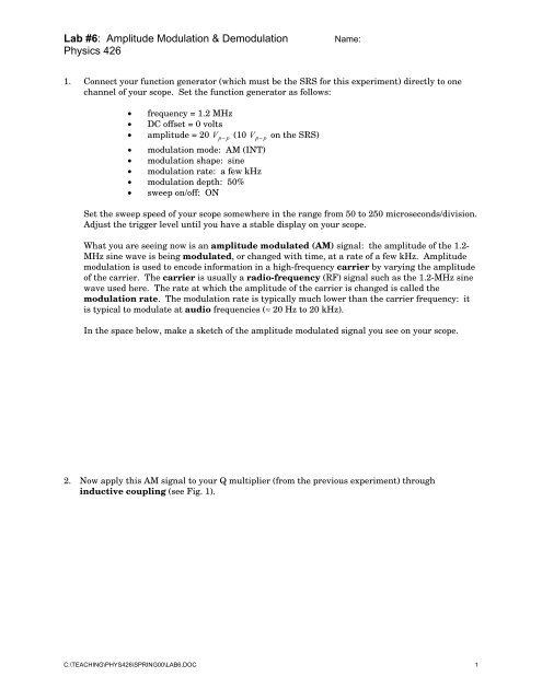
1. Connect your function generator (which must be the SRS for this experiment) directly to one<br />
channel of your scope. Set the function generator as follows:<br />
• frequency = 1.2 MHz<br />
• DC offset = 0 volts<br />
• amplitude = 20 V p− p (10 V p− p on the SRS)<br />
• modulation mode: AM (INT)<br />
• modulation shape: sine<br />
• modulation rate: a few kHz<br />
• modulation depth: 50%<br />
• sweep on/off: ON<br />
Set the sweep speed of your scope somewhere in the range from 50 to 250 microseconds/division.<br />
Adjust the trigger level until you have a stable display on your scope.<br />
What you are seeing now is an amplitude modulated (AM) signal: the amplitude of the 1.2-<br />
MHz sine wave is being modulated, or changed with time, at a rate of a few kHz. <strong>Amplitude</strong><br />
modulation is used to encode information in a high-frequency carrier by varying the amplitude<br />
of the carrier. The carrier is usually a radio-frequency (RF) signal such as the 1.2-MHz sine<br />
wave used here. The rate at which the amplitude of the carrier is changed is called the<br />
modulation rate. The modulation rate is typically much lower than the carrier frequency: it<br />
is typical to modulate at audio frequencies (≈ 20 Hz to 20 kHz).<br />
In the space below, make a sketch of the amplitude modulated signal you see on your scope.<br />
2. Now apply this AM signal to your Q multiplier (from the previous experiment) through<br />
inductive coupling (see Fig. 1).<br />
C:\TEACHING\PHYS<strong>426</strong>\SPRING00\LAB6.DOC 1
<strong>Lab</strong> <strong>#6</strong>: <strong>Amplitude</strong> <strong>Modulation</strong> & <strong>Demodulation</strong><br />
<strong>Physics</strong> <strong>426</strong><br />
L1<br />
L2<br />
Figure 1. RF generator providing input signal to Q multiplier through inductive coupling.<br />
2. Monitor the SRS/PRAGMATIC on one channel of your scope. Look at the output of the Q<br />
multiplier on the other channel. In the space below, sketch the Q multiplier output.<br />
C:\TEACHING\PHYS<strong>426</strong>\SPRING00\LAB6.DOC 2
<strong>Lab</strong> <strong>#6</strong>: <strong>Amplitude</strong> <strong>Modulation</strong> & <strong>Demodulation</strong><br />
<strong>Physics</strong> <strong>426</strong><br />
3. See whether you can tune the Q multiplier through the AM carrier frequency. In the space<br />
below, comment on what happens to the Q multiplier output when you do this.<br />
4. Change the positive feedback setting of your Q multiplier through its entire range. In the space<br />
below, comment on what happens to the Q multiplier output when you do this.<br />
5. In the space on your breadboard just to the right of the Q multiplier, build the AM demodulator<br />
(see Fig. 2).<br />
Figure 2. AM demodulator.<br />
C:\TEACHING\PHYS<strong>426</strong>\SPRING00\LAB6.DOC 3
<strong>Lab</strong> <strong>#6</strong>: <strong>Amplitude</strong> <strong>Modulation</strong> & <strong>Demodulation</strong><br />
<strong>Physics</strong> <strong>426</strong><br />
6. On your scope, look simultaneously at the SRS/PRAGMATIC (still in the AM mode) and the<br />
AUDIO OUT signal from the demodulator. Try to “match” the audio with the envelope of the<br />
AM signal. In the space below, comment on how well they match. Which edge of the AM<br />
envelope (upper or lower edge) does the audio match<br />
7. Remove L1 and turn the SRS/PRAGMATIC OFF. Using clip leads, connect the upper end of L2<br />
to the antenna distributed throughout the lab. Use a 50-100pF capacitor to couple the<br />
antenna to your tuned inductor, as shown in Figure 3. Try to tune your Q multiplier<br />
(which is really now an AM receiver) to some AM broadcast station (WTAW 1150 kHz, e.g.). On<br />
your scope, observe the AM signal at the source follower output. Try to correlate what you see on<br />
the scope with the audio that you hear from the radio receiver in the lab (provided by your<br />
instructors). In the space below, comment on how good this correlation seems to be.<br />
C:\TEACHING\PHYS<strong>426</strong>\SPRING00\LAB6.DOC 4
<strong>Lab</strong> <strong>#6</strong>: <strong>Amplitude</strong> <strong>Modulation</strong> & <strong>Demodulation</strong><br />
<strong>Physics</strong> <strong>426</strong><br />
Figure 3. Q-multiplier portion of AM receiver, showing antenna connected<br />
to upper end of L2 using 50-100 pF coupling capacitor. (AM receiver circuit<br />
also includes demodulator shown in Figure 2.)<br />
8. With your AM receiver tuned to an AM broadcast station (and with the positive feedback<br />
adjusted so that your receiver does not oscillate on its own), look at the input to the<br />
demodulator and the output from it simultaneously on the scope. Try to match up the<br />
demodulator audio output with the envelope of the AM carrier. Which edge of the envelope<br />
(upper or lower) does the audio seem to follow<br />
9. Now turn the diode in your demodulator around so that it now conducts in the opposite direction.<br />
Which edge of the envelope of the AM signal are you detecting now Explain this result in terms<br />
of the effect that reversing the diode has on the details of the operation of the demodulator. That<br />
is, what is different about what’s now going on in the demodulator circuit, and how does this<br />
account for the effect that you’ve just witnessed (You may use the back of this sheet.)<br />
C:\TEACHING\PHYS<strong>426</strong>\SPRING00\LAB6.DOC 5
<strong>Lab</strong> <strong>#6</strong>: <strong>Amplitude</strong> <strong>Modulation</strong> & <strong>Demodulation</strong><br />
<strong>Physics</strong> <strong>426</strong><br />
10. Now build the LM386 audio power amplifier circuit shown in Figure 4. Try to do this on the<br />
same breadboard you’ve been using (i.e., inside your aluminum BUD chassis). You may not be<br />
able to fit another circuit on the “front” half of this breadboard, but remember that you do have<br />
another similar section of breadboard to work with toward the rear of the box.<br />
speaker<br />
Figure 4. LM386 audio power amplifier (gain ≈ 200).<br />
11. Try tuning your AM radio receiver to as many different AM stations as you can. When you locate<br />
new stations, use a local oscillator (your SRS or PRAGMATIC) to produce beats so that you<br />
can determine the carrier frequency of the AM station you’ve found (be sure to see the demo on<br />
this in class). Record all the carrier frequencies of the stations you find (and their call letters, if<br />
you can).<br />
C:\TEACHING\PHYS<strong>426</strong>\SPRING00\LAB6.DOC 6