

Clutch - CelicaTech
Clutch - CelicaTech
Clutch - CelicaTech

Create successful ePaper yourself
Turn your PDF publications into a flip-book with our unique Google optimized e-Paper software.
mount-to-crossmember bolts/nuts.<br />
7) Remove front (exhaust manifold side) engine mount and rear<br />
(intake manifold side) engine mount brackets from cylinder block.<br />
Remove bolts and crossmember, located below engine and transaxle.<br />
Remove transaxle mount bolts.<br />
8) Remove remaining transaxle mounting bolts. Slightly lower<br />
engine and remove transaxle. Place a reference mark on clutch cover<br />
and flywheel for reassembly reference.<br />
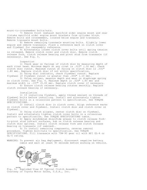
9) Alternately loosen clutch cover bolts until spring tension<br />
is released. Remove clutch cover and clutch disc. Remove clutch<br />
release fork, clutch release bearing and pivot stud from transaxle (if<br />
necessary). See Fig. 5.<br />
Inspection<br />
1) Check wear on facings of clutch disc by measuring depth of<br />
each rivet head. Minimum depth at any rivet is .012" (.30 mm). Check<br />
clutch disc runout. Maximum runout at facing on clutch disc is .031"<br />
(.80 mm). Replace clutch disc if not within specification.<br />
2) Using dial indicator, check flywheel runout. Replace<br />
flywheel if flywheel runout is greater than .004" (.10 mm).<br />
3) Using caliper, measure depth and wear on diaphragm spring<br />
on clutch cover. See Fig. 6. Maximum depth is .024" (.60 mm) and<br />
maximum width is .197" (5.00 mm). Replace clutch cover if necessary.<br />
4) Ensure clutch release bearing rotates smoothly. Replace<br />
clutch release bearing if necessary.<br />
Installation<br />
1) If installing flywheel, apply thread sealant on threads of<br />
flywheel bolts before installing. Install and alternately tighten<br />
flywheel bolts in a crisscross pattern to specification. See TORQUE<br />
SPECIFICATIONS.<br />
2) Install clutch disc in clutch cover. Align reference marks<br />
on clutch cover and flywheel. Install clutch disc and clutch cover on<br />
flywheel.<br />
3) Using clutch aligner, center clutch disc on flywheel.<br />
Install and alternately tighten clutch cover bolts in a crisscross<br />
pattern to specification. See TORQUE SPECIFICATIONS table.<br />
4) Apply molybdenum disulfide grease to clutch release forkto-pivot<br />
stud contact surfaces, hub on clutch release bearing and<br />
clutch disc splines. Install clutch release fork and clutch release<br />
bearing on transaxle (if removed).<br />
5) To install remaining components, reverse removal<br />
procedure. Tighten bolt/nuts to specification. See TORQUE<br />
SPECIFICATIONS. Fill transaxle with 75W-90 gear oil with API GL-4 or<br />
GL-5 rating.<br />
WARNING: To prevent air bag deployment, disconnect negative battery<br />
cable and wait at least 90 seconds before working on vehicle.<br />
Fig. 5: Exploded View Of Typical <strong>Clutch</strong> Assembly<br />
Courtesy of Toyota Motor Sales, U.S.A., Inc.


