LDT Digital-Compendium FL-multiMAUS-DC-001_10_engl
LDT Digital-Compendium FL-multiMAUS-DC-001_10_engl
LDT Digital-Compendium FL-multiMAUS-DC-001_10_engl

You also want an ePaper? Increase the reach of your titles
YUMPU automatically turns print PDFs into web optimized ePapers that Google loves.
<strong>LDT</strong> <strong>Digital</strong>-<strong>Compendium</strong> (<strong>FL</strong>-<strong>multiMAUS</strong>-<strong>DC</strong>-<strong>001</strong>_<strong>10</strong>_<strong>engl</strong>)<br />
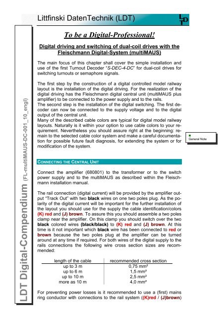
Littfinski DatenTechnik (<strong>LDT</strong>)<br />
To be a <strong>Digital</strong>-Professional!<br />
<strong>Digital</strong> driving and switching of dual-coil drives with the<br />
Fleischmann <strong>Digital</strong>-System (<strong>multiMAUS</strong>)<br />
The main focus of this chapter shall cover the simple installation and<br />
use of the first Turnout Decoder “S-DEC-4-<strong>DC</strong>” for dual-coil drives for<br />
switching turnouts or semaphore signals.<br />
The first step by the construction of a digital controlled model railway<br />
layout is the installation of the digital driving. For the realization of the<br />
digital driving has the Fleischmann digital central unit (<strong>multiMAUS</strong> plus<br />
amplifier) to be connected to the power supply and to the rails.<br />
The second step is the installation of the digital switching. The first decoder<br />
can now be connected to the supply voltage and to the digital<br />
output of the central unit.<br />
Many of the described cable colors are typical for digital model railway<br />
layouts. Naturally is it within your option to use cable colors to your requirement.<br />
Nevertheless you should assure right at the beginning: remain<br />
to the selected cable color system and make a careful documentation<br />
for possible future fault diagnosis, for extending the system or for<br />
modification of the system.<br />
CONNECTING THE CENTRAL UNIT<br />
Connect the amplifier (680801) to the transformer or to the switch<br />
power supply and to the <strong>multiMAUS</strong> as described within the Fleischmann<br />
installation manual.<br />
The rail connection (digital current) will be provided by the amplifier output<br />
“Track Out” with two black wires on one two poles plug. As the polarity<br />
of the digital current will be important for the further installation of<br />
the layout you should use for the supply the cable identification/colors<br />
(K) red and (J) brown. To assure this you should assemble a two poles<br />
clamp near the amplifier. On this clamp you should switch over the two<br />
black colored wires (black/black) to (K) red and (J) brown. At this<br />
time is it not important which black wire has been connected to red or<br />
brown because the two poles plug at the amplifier can be turned<br />
around at any time if required. For both wires of the digital supply to the<br />
rails connections the following wire cross section sizes are recommended:<br />
length of the cable<br />
up to 3 m<br />
up to 6 m<br />
up to <strong>10</strong> m<br />
more as <strong>10</strong> m<br />
recommended cross section<br />
0,75 mm²<br />
1,5 mm²<br />
2,5 mm²<br />
4,0 mm²<br />
For preventing power losses is it recommended to use a (first) mains<br />
ring conductor with connections to the rail system ((K)red / (J)brown)<br />
•<br />
General Note
2abc<br />
5jkl<br />
8tuv<br />
Littfinski DatenTechnik (<strong>LDT</strong>)<br />
D-25492 Heist/Germany • Kleiner Ring 9 • www.ldt-infocenter.com<br />
at distances of 1,5 to 2m. Each plugged rail connection will contain an<br />
electrical resistance. This resistance will be enlarged by corroded contacts<br />
etc. The resulting voltage drop at the rail connections reduces the<br />
digital voltage and it can be possible that “remote” track sections will<br />
eventually not get the full digital current – disturbances or inexplicable<br />
abnormal behavior can be expected. A sufficient diameter of the supplywire<br />
contains a considerable lower resistance and assures therefore the<br />
full supply of the voltage to the rails.<br />
The below picture sample shows the general connection of a central<br />
unit and the additional power supply connections at your model railway<br />
layout:<br />
rot<br />
red<br />
braun<br />
brown<br />
rot<br />
red<br />
braun<br />
brown<br />
<strong>FL</strong>EISCHMANN<br />
<strong>multiMAUS</strong><br />
STOP<br />
schwarz<br />
black<br />
schwarz<br />
black<br />
OK<br />
<strong>FL</strong>EISCHMANN<br />
680801<br />
1<br />
4ghi<br />
7pqrs<br />
def3<br />
mno6<br />
wxyz9<br />
0<br />
MENU<br />
•<br />
Connection of the<br />
Fleischmann<br />
digital central unit<br />
(page_899)<br />
Power Track Booster<br />
in out out<br />
Slave<br />
Master<br />
Nur für trockene Räume, Keep dry<br />
Vom Modellbahntrafo<br />
From transformer<br />
THE FIRST TURNOUT-DECODERS (S-DEC-4-<strong>DC</strong>)<br />
Now to the second step for the digital switching of your digital model<br />
railway layout. Also the Turnout-Decoders requires a connection to the<br />
power supply (14 – 18 V ~) and to the digital voltage. All digital commands<br />
as well as to the loc-decoders will be transmitted on this way.<br />
The Fleischmann <strong>Digital</strong>-System transmits data with the <strong>DC</strong>C-format for<br />
the driving of the locomotives and the switching of the turnout decoders.<br />
For the controlling of dual coil drives is therefore the application of a 4-<br />
fold turnout decoder “S-DEC-4-<strong>DC</strong>” suitable.<br />
Page 2 / 8<br />
<strong>LDT</strong> <strong>Digital</strong>-<strong>Compendium</strong> <strong>FL</strong>-<strong>multiMAUS</strong>-<strong>DC</strong>-<strong>001</strong>_<strong>10</strong>_<strong>engl</strong>
J<br />
K<br />
J<br />
K<br />
J<br />
K<br />
Littfinski DatenTechnik (<strong>LDT</strong>)<br />
D-25492 Heist/Germany • Kleiner Ring 9 • www.ldt-infocenter.com<br />
Modellbahntrafo<br />
Transformer<br />
14..18V~<br />
Von Steuereinheit<br />
oder Booster<br />
From command station<br />
or booster<br />
braun<br />
brown<br />
rot<br />
red<br />
~ ~<br />
14 .. 18V<br />
Littfinski DatenTechnik (<strong>LDT</strong>) 1 R<br />
G G 2 R<br />
KL2<br />
4fach Weichendecoder<br />
Accessory Decoder<br />
S-DEC-4<br />
Rev. 2.1<br />
Multi-<strong>Digital</strong><br />
Littfinski DatenTechnik<br />
D-25492 Heist<br />
www.ldt-infocenter.com<br />
Für 4 Doppelspulenantriebe für NMRA <strong>DC</strong>C<br />
<strong>Digital</strong>systeme. Schaltstrom: 1 Ampere pro<br />
Ausgang.<br />
Magnetartikel-Decoder<br />
S-DEC-4-<strong>DC</strong><br />
<strong>Digital</strong>-Profi werden!<br />
KL1<br />
Red<br />
J<br />
Black<br />
K<br />
G S1 red brown<br />
G 3 R 4 R<br />
•<br />
Connection of the<br />
Turnout-Decoder<br />
S-DEC-4-<strong>DC</strong><br />
(page_<strong>10</strong>1)<br />
Power supply (black cables at the above sample) will be required for the<br />
module itself and the switching of the coil drives. The decoder module<br />
requires a spacing current flow of about 0,1 Ampere. Each of the four<br />
outputs can cover a maximum switching current load of up to 1 Ampere.<br />
By connecting the supply voltage of 14 – 18 Volt ~ please pay<br />
careful attention that you use the two inputs of the clamp KL2 which are<br />
marked with “~”. One of the two terminals of the supply voltage should<br />
never be connected to the ground output “┴” of the 3 poles clamp KL2.<br />
In this case the decoder will be destroyed as shown within the following<br />
connection sample.<br />
Modellbahntrafo<br />
Transformer<br />
14..18V~<br />
Modellbahntrafo<br />
Transformer<br />
14..18V~<br />
Modellbahntrafo<br />
Transformer<br />
14..18V~<br />
•<br />
Correct connection<br />
of the external<br />
supply voltage<br />
(page_508)<br />
<strong>Digital</strong>-Profi werden!<br />
Magnetartikel-Decoder<br />
S-DEC-4-<strong>DC</strong><br />
Für 4 Doppelspulenantriebe für NMRA <strong>DC</strong>C<br />
<strong>Digital</strong>systeme. Schaltstrom: 1 Ampere pro<br />
Ausgang.<br />
Multi-<strong>Digital</strong><br />
Littfinski DatenTechnik<br />
D-25492 Heist<br />
www.ldt-infocenter.com<br />
KL2<br />
~ ~<br />
14 .. 18V<br />
4fach Weichendecoder<br />
Accessory Decoder<br />
S-DEC-4<br />
Rev. 2.1<br />
Littfinski DatenTechnik (<strong>LDT</strong>)<br />
1 R<br />
G G 2 R<br />
KL1<br />
Black Red<br />
G 3 R G 4 R<br />
red brown<br />
S1 KL1<br />
Black Red<br />
G 3 R G 4 R<br />
red brown<br />
S1 <strong>Digital</strong>-Profi werden!<br />
Magnetartikel-Decoder<br />
S-DEC-4-<strong>DC</strong><br />
Für 4 Doppelspulenantriebe für NMRA <strong>DC</strong>C<br />
<strong>Digital</strong>systeme. Schaltstrom: 1 Ampere pro<br />
Ausgang.<br />
Multi-<strong>Digital</strong><br />
Littfinski DatenTechnik<br />
D-25492 Heist<br />
www.ldt-infocenter.com<br />
KL2<br />
~ ~<br />
14 .. 18V<br />
4fach Weichendecoder<br />
Accessory Decoder<br />
S-DEC-4<br />
Rev. 2.1<br />
Littfinski DatenTechnik (<strong>LDT</strong>) 1 R<br />
G G 2 R<br />
<strong>Digital</strong>-Profi werden!<br />
Magnetartikel-Decoder<br />
S-DEC-4-<strong>DC</strong><br />
Für 4 Doppelspulenantriebe für NMRA <strong>DC</strong>C<br />
<strong>Digital</strong>systeme. Schaltstrom: 1 Ampere pro<br />
Ausgang.<br />
Multi-<strong>Digital</strong><br />
Littfinski DatenTechnik<br />
D-25492 Heist<br />
www.ldt-infocenter.com<br />
KL2<br />
~ ~<br />
14 .. 18V<br />
4fach Weichendecoder<br />
Accessory Decoder<br />
S-DEC-4<br />
Rev. 2.1<br />
Littfinski DatenTechnik (<strong>LDT</strong>) 1 R<br />
G G 2 R<br />
KL1<br />
Black Red<br />
G 3 R G 4 R<br />
red brown<br />
S1 The turnouts or signals have to be connected with three cables (blue /<br />
yellow / blue), which can be of a preferable short length, by a considerable<br />
close distance of the decoder to the respective turnout or signal.<br />
The common conductor of the turnout- or signal-drive (yellow) shall be<br />
connected to the middle contact of the decoder module marked by a<br />
digit. The clamps marked with “G” and “R” are supposed for the coil<br />
drives and are indicating the turnout position to be switched (G for<br />
straight and R for round).<br />
<strong>LDT</strong> <strong>Digital</strong>-<strong>Compendium</strong> <strong>FL</strong>-<strong>multiMAUS</strong>-<strong>DC</strong>-<strong>001</strong>_<strong>10</strong>_<strong>engl</strong> Page 3 / 8
Littfinski DatenTechnik (<strong>LDT</strong>)<br />
D-25492 Heist/Germany • Kleiner Ring 9 • www.ldt-infocenter.com<br />
•<br />
General Note<br />
If it is required to extend the connection cables of a turnout drive it has<br />
to be taken care of a sufficient diameter of the connection wires. For a<br />
maximum current of 1 Ampere at the decoder output is the ordinary<br />
used wiring of 0,14 mm² not sufficient. We recommend to use wires of<br />
0,5 mm² for a sufficient installation.<br />
It is possible to use the digital current for the supply to the decoder<br />
modules. This should be installed on small layouts only because in this<br />
case the expensive digital current will be “wasted” for the current supply<br />
to the decoders and for switching the drives.<br />
Von Steuereinheit<br />
oder Booster<br />
From command station<br />
or booster<br />
braun<br />
brown<br />
rot<br />
red<br />
•<br />
Current Supply to<br />
the S-DEC-4-<strong>DC</strong><br />
via the <strong>Digital</strong><br />
Current<br />
(page_<strong>10</strong>2)<br />
~ ~<br />
14 .. 18V<br />
Littfinski DatenTechnik (<strong>LDT</strong>) 1 R<br />
G G 2 R<br />
KL2<br />
4fach Weichendecoder<br />
Accessory Decoder<br />
S-DEC-4<br />
Rev. 2.1<br />
Multi-<strong>Digital</strong><br />
Littfinski DatenTechnik<br />
D-25492 Heist<br />
www.ldt-infocenter.com<br />
Für 4 Doppelspulenantriebe für NMRA <strong>DC</strong>C<br />
<strong>Digital</strong>systeme. Schaltstrom: 1 Ampere pro<br />
Ausgang.<br />
Magnetartikel-Decoder<br />
S-DEC-4-<strong>DC</strong><br />
<strong>Digital</strong>-Profi werden!<br />
KL1<br />
Red<br />
Black<br />
J<br />
G S1 red brown<br />
K<br />
G 3 R 4 R<br />
If the available digital current supply from the amplifier 680801 for driving<br />
and operating the layout will be insufficient is it required to use additional<br />
digital amplifiers. This requires naturally additional wiring installation<br />
and further cost (expensive digital current).<br />
You can extend your Fleischmann <strong>Digital</strong> Layout by up to <strong>10</strong> <strong>Digital</strong>-<br />
Booster “DB-2” by using the Adapter “Adap-Roco”. Each <strong>Digital</strong>Booster<br />
“DB-2” supplies an additional current of 2,5 Ampere.<br />
Page 4 / 8<br />
<strong>LDT</strong> <strong>Digital</strong>-<strong>Compendium</strong> <strong>FL</strong>-<strong>multiMAUS</strong>-<strong>DC</strong>-<strong>001</strong>_<strong>10</strong>_<strong>engl</strong>
Multi-<strong>Digital</strong><br />
Multi-<strong>Digital</strong><br />
1<br />
4ghi<br />
7pqrs<br />
STOP<br />
2abc<br />
5jkl<br />
8tuv<br />
0<br />
<strong>multiMAUS</strong><br />
Littfinski DatenTechnik (<strong>LDT</strong>)<br />
D-25492 Heist/Germany • Kleiner Ring 9 • www.ldt-infocenter.com<br />
The next sample shows the connection of two from four possible<br />
turnouts and the connection of a further decoder module for additional<br />
four turnouts.<br />
1<br />
2<br />
1 2<br />
<strong>FL</strong>EISCHMANN<br />
KL1<br />
Red<br />
J<br />
Black<br />
K<br />
G S1 red brown<br />
G 3 R 4 R<br />
<strong>Digital</strong>-Profi werden!<br />
Magnetartikel-Decoder<br />
S-DEC-4-<strong>DC</strong><br />
Für 4 Doppelspulenantriebe für NMRA <strong>DC</strong>C<br />
<strong>Digital</strong>systeme. Schaltstrom: 1 Ampere pro<br />
Ausgang.<br />
Littfinski DatenTechnik<br />
D-25492 Heist<br />
www.ldt-infocenter.com<br />
braun<br />
brown<br />
schwarz<br />
black<br />
rot<br />
red<br />
schwarz<br />
black<br />
<strong>FL</strong>EISCHMANN<br />
680801<br />
OK<br />
def3<br />
mno6<br />
wxyz9<br />
MENU<br />
•<br />
Connecting several<br />
Turnout<br />
Decoders<br />
S-DEC-4-<strong>DC</strong><br />
(page_900)<br />
KL2<br />
4fach Weichendecoder<br />
Accessory Decoder<br />
S-DEC-4<br />
~ ~<br />
Rev. 2.1<br />
14 .. 18V<br />
Littfinski DatenTechnik (<strong>LDT</strong>) G 1 R<br />
G 2 R<br />
KL2<br />
4fach Weichendecoder<br />
Accessory Decoder<br />
S-DEC-4<br />
~ ~<br />
Rev. 2.1<br />
14 .. 18V<br />
Littfinski DatenTechnik (<strong>LDT</strong>) G 1 R<br />
G 2 R<br />
Power Track Booster<br />
in out out<br />
Slave<br />
Master<br />
Nur für trockene Räume, Keep dry<br />
Vom Modellbahntrafo<br />
From transformer<br />
Vom Modellbahntrafo<br />
From transformer<br />
It is recommended to install a separate second main ring conductor for<br />
the digital current to the turnout- and switch decoders ((K) red / (J)<br />
brown) and a third main ring conductor for the voltage supply (black).<br />
The digital information for the accessory decoders should never be<br />
taken directly from the rails. The driving locomotives can influence the<br />
digital signal by producing continually a kind of loose contact signal.<br />
This can result to the problem that the decoder cannot understand the<br />
single signal. For this reason will be the loc commands continually repeated.<br />
Especially for the switch commands which will not be transmitted several<br />
times as done by the loc commands is it possible that commands<br />
will be getting lost if the digital information have been taken directly<br />
from the rails.<br />
<strong>LDT</strong> <strong>Digital</strong>-<strong>Compendium</strong> <strong>FL</strong>-<strong>multiMAUS</strong>-<strong>DC</strong>-<strong>001</strong>_<strong>10</strong>_<strong>engl</strong> Page 5 / 8
Littfinski DatenTechnik (<strong>LDT</strong>)<br />
D-25492 Heist/Germany • Kleiner Ring 9 • www.ldt-infocenter.com<br />
Ringleitung <strong>Digital</strong>strom<br />
Ring conductor digital current<br />
rot / K<br />
red / K<br />
braun / J<br />
brown / J<br />
G 3 R 4 R<br />
Black<br />
K<br />
G S1 red brown<br />
KL1<br />
Red<br />
J<br />
G 3 R 4 R<br />
Black<br />
K<br />
G S1 red brown<br />
KL1<br />
Red<br />
J<br />
<strong>Digital</strong>-Profi werden!<br />
Magnetartikel-Decoder<br />
S-DEC-4-<strong>DC</strong><br />
Für 4 Doppelspulenantriebe für NMRA <strong>DC</strong>C<br />
<strong>Digital</strong>systeme. Schaltstrom: 1 Ampere pro<br />
Ausgang.<br />
Littfinski DatenTechnik<br />
Multi-<strong>Digital</strong><br />
D-25492 Heist<br />
www.ldt-infocenter.com<br />
•<br />
2. and 3.<br />
Main Ring Conductor<br />
for accessory<br />
Decoders<br />
(page_260)<br />
KL2<br />
~ ~<br />
14 .. 18V<br />
4fach Weichendecoder<br />
Accessory Decoder<br />
S-DEC-4<br />
Rev. 2.1<br />
Littfinski DatenTechnik (<strong>LDT</strong>)<br />
G 1 R<br />
G 2 R<br />
KL2<br />
~ ~<br />
14 .. 18V<br />
4fach Weichendecoder<br />
Accessory Decoder<br />
S-DEC-4<br />
Rev. 2.1<br />
Littfinski DatenTechnik (<strong>LDT</strong>)<br />
G 1 R<br />
G 2 R<br />
Ringleitung Versorgung<br />
Ring conductor supply<br />
There are as well some recommendations for the wire cross-section<br />
dimension of the two main ring conductor wires. As there will be a low<br />
current flow only the wire dimension can be a little smaller.<br />
length of the cable<br />
up to <strong>10</strong> m<br />
more as <strong>10</strong> m<br />
recommended cross section<br />
0,75 mm²<br />
1,0 - 1,5 mm²<br />
At least after completion of the wiring installation you should start a first<br />
test and the placing of a suitable digital address for the turnout (or signal).<br />
THE FIRST PROGRAMMING<br />
The assignment of digital addresses has to be carried out individually<br />
for each module. The address is valid for the respective complete group<br />
of four (e.g. 1 - 4, 5 - 8, 9 - 12 etc.). For setting the address (= read-in<br />
address) you have to connect a turnout to the output 1 at the module.<br />
The turnout will start switching at a 1,5 second interval after activating<br />
the programming key at the decoder. The decoder module is now in a<br />
learning mode. Now is it required to select and activate a turnout (1 – 4,<br />
5 – 8, etc.) at the <strong>multiMAUS</strong>. The decoder module takes over the four<br />
addresses for the four outputs and confirms the setting by switching the<br />
connected turnout for a short period a little faster.<br />
If the decoder does not confirm the setting by an accelerated switching<br />
of the turnout you should turn around the 2-poles plug at the amplifier<br />
output “Track Out”. This will match the correct polarity of the digital current<br />
for all decoders.<br />
Page 6 / 8<br />
<strong>LDT</strong> <strong>Digital</strong>-<strong>Compendium</strong> <strong>FL</strong>-<strong>multiMAUS</strong>-<strong>DC</strong>-<strong>001</strong>_<strong>10</strong>_<strong>engl</strong>
Littfinski DatenTechnik (<strong>LDT</strong>)<br />
D-25492 Heist/Germany • Kleiner Ring 9 • www.ldt-infocenter.com<br />
Depressing again the programming key at the decoder will complete the<br />
setting of addresses. The addresses are now permanently stored at the<br />
decoder.<br />
Our tip: Carry out the set-up of digital addresses before installing the<br />
decoder module below the layout because the handling of the module<br />
with all connections is much easier at a working bench. After address<br />
setting please mark the module with the assigned digital addresses<br />
(e.g. label marked with a pencil “5 – 8” for the second group of four addresses).<br />
•<br />
General Note<br />
With this procedure the functional test has been already performed and<br />
a later malfunction after installation (e.g. defect module) can be prevented.<br />
After final installation of the unit this would be a difficult time<br />
consuming procedure.<br />
SUPPRESSION OF INTERFERENCES<br />
End-off switched coil drives of turnouts can initiate interferences and<br />
therefore influencing the digital system e.g. with unreliable switching of<br />
turnouts. This problem can be solved by slipping <strong>10</strong> ferrite pearls onto<br />
the common connection wire (yellow) of the turnout drives. This has to<br />
be done very close to the coil housing.<br />
•<br />
Technical Tip<br />
Modellbahntrafo<br />
Transformer<br />
14..18V~<br />
Von Steuereinheit<br />
oder Booster<br />
From command station<br />
or booster<br />
braun<br />
brown<br />
rot<br />
red<br />
<strong>10</strong> Ferritperlen zur<br />
Unterdrückung von<br />
Störungen durch<br />
endabgeschaltete<br />
Weichenantriebe.<br />
Bestellbezeichnung: FP<br />
<strong>10</strong> ferrit perls for<br />
suppression of<br />
interferences caused<br />
by end-off switched turnouts.<br />
Order code: FP<br />
~ ~<br />
14 .. 18V<br />
Littfinski DatenTechnik (<strong>LDT</strong>) 1 R<br />
G G 2 R<br />
KL2<br />
4fach Weichendecoder<br />
Accessory Decoder<br />
S-DEC-4<br />
Rev. 2.1<br />
Multi-<strong>Digital</strong><br />
Littfinski DatenTechnik<br />
D-25492 Heist<br />
www.ldt-infocenter.com<br />
Für 4 Doppelspulenantriebe für NMRA <strong>DC</strong>C<br />
<strong>Digital</strong>systeme. Schaltstrom: 1 Ampere pro<br />
Ausgang.<br />
Magnetartikel-Decoder<br />
S-DEC-4-<strong>DC</strong><br />
<strong>Digital</strong>-Profi werden!<br />
KL1<br />
Red<br />
Black<br />
J<br />
G S1 red brown<br />
K<br />
G 3 R 4 R<br />
•<br />
Ferrite Pearls for<br />
the suppression of<br />
interferences by<br />
Coil Drives<br />
(page_239)<br />
The ferrite pearls are available by <strong>LDT</strong> under the order code “FP”. The<br />
connections and the operation of the turnouts as well as the programming<br />
the decoder will not be influenced.<br />
<strong>LDT</strong> <strong>Digital</strong>-<strong>Compendium</strong> <strong>FL</strong>-<strong>multiMAUS</strong>-<strong>DC</strong>-<strong>001</strong>_<strong>10</strong>_<strong>engl</strong> Page 7 / 8
Littfinski DatenTechnik (<strong>LDT</strong>)<br />
D-25492 Heist/Germany • Kleiner Ring 9 • www.ldt-infocenter.com<br />
SPECIAL CASE: PIKO A-RAIL DRIVES<br />
The turnout drives of company PIKO (A-track) have to be operated with<br />
a reduced current to prevent the bouncing of the turnout latch und to<br />
assure that the current consumption will be below 1 Ampere.<br />
For the prevention is it recommended to implement at this drives at the<br />
common connection (yellow) a resistor with 4,7Ω (1W). This resistor<br />
will reduce the current on both drive coils and will assure a safer operation.<br />
Modellbahntrafo<br />
Transformer<br />
14..18V~<br />
Von Steuereinheit<br />
oder Booster<br />
From command station<br />
or booster<br />
braun<br />
brown<br />
rot<br />
red<br />
•<br />
Serial Resistor for<br />
PIKO-Turnouts<br />
(page_256)<br />
Widerstand 4,7R/1W<br />
Bestellbezeichnung: RES4R7<br />
Resistor 4,7R/1W<br />
Order code: RES4R7<br />
~ ~<br />
14 .. 18V<br />
Littfinski DatenTechnik (<strong>LDT</strong>) 1 R<br />
G G 2 R<br />
KL2<br />
4fach Weichendecoder<br />
Accessory Decoder<br />
S-DEC-4<br />
Rev. 2.1<br />
Multi-<strong>Digital</strong><br />
Littfinski DatenTechnik<br />
D-25492 Heist<br />
www.ldt-infocenter.com<br />
Für 4 Doppelspulenantriebe für NMRA <strong>DC</strong>C<br />
<strong>Digital</strong>systeme. Schaltstrom: 1 Ampere pro<br />
Ausgang.<br />
Magnetartikel-Decoder<br />
S-DEC-4-<strong>DC</strong><br />
<strong>Digital</strong>-Profi werden!<br />
KL1<br />
Red<br />
Black<br />
J<br />
G S1 red brown<br />
K<br />
G 3 R 4 R<br />
The resistor is available as accessory by <strong>LDT</strong> under the order code<br />
“RES4R7”. There will be no change within the connections or the<br />
operation of the turnouts as well as on the programming of the decoder.<br />
For the suppression of interferences by those end-off switched turnouts<br />
is it recommended to apply the ferrite pearls as well on the common<br />
connection (yellow) of the turnouts “Suppression of interferences”<br />
(Page 7).<br />
FURTHER INFORMATION<br />
•<br />
Internet:<br />
http://www.ldtinfocenter.com<br />
Additional information about the operation of digital model railway components<br />
and further helpful connection samples are available within the<br />
operation instructions received with every purchased module and device<br />
and at our extensive Internet page. All mentioned sample connections<br />
can be loaded down as PDF files (e.g. page_899.pdf) and printed<br />
at an A4 format.<br />
Authors: Harry Kellner / Peter Littfinski<br />
Subject to technical changes and errors.<br />
© 02/20<strong>10</strong> by <strong>LDT</strong><br />
Page 8 / 8<br />
<strong>LDT</strong> <strong>Digital</strong>-<strong>Compendium</strong> <strong>FL</strong>-<strong>multiMAUS</strong>-<strong>DC</strong>-<strong>001</strong>_<strong>10</strong>_<strong>engl</strong>