Guide Specifications - Power & Systems Innovations
Guide Specifications - Power & Systems Innovations
Guide Specifications - Power & Systems Innovations

You also want an ePaper? Increase the reach of your titles
YUMPU automatically turns print PDFs into web optimized ePapers that Google loves.
<strong>Guide</strong><br />
<strong>Specifications</strong><br />
TransGuard 7/27/02<br />
CURRENT<br />
TECHNOLOGY<br />
®<br />
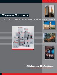
TransGuard<br />
TransGuard<br />
®<br />
Electrical<br />
Transient<br />
Suppression<br />
Filter<br />
<strong>Systems</strong><br />
CURRENT TECHNOLOGY ® TRANSGUARD ® INSTALLATION, OPERATION AND MAINTENANCE MANUAL
1.0 GENERAL<br />
1.1 SUMMARY. These specifications describe the electrical and mechanical requirements for a<br />
hybrid electrical transient surge suppression filter system integrating both transient voltage surge<br />
suppression (TVSS) and electrical high frequency noise filtering for exposure locations as defined in<br />
ANSI/IEEE C62.41-1991.<br />
The unit shall be designed for parallel connection to the facility's wiring system. The suppression<br />
filter system shall be designed and manufactured in the USA by a qualified manufacturer of<br />
suppression filter system equipment. The qualified manufacturer shall have been engaged in the<br />
commercial design and manufacture of such products for a minimum of five (5) years.<br />
These specifications are based on Current Technology's TransGuard ® suppression filter systems.<br />
Other manufacturers shall provide detailed compliance or exception statements, along with<br />
required test documentation, to all provisions of this specification fourteen (14) days prior to bid.<br />
1.2 STANDARDS. The specified unit shall be designed, manufactured, tested and installed in<br />
compliance with the following standards:<br />
ANSI/IEEE C62.41-1991 and C62.45-1992;<br />
ANSI/IEEE C62.1 and C62.11;<br />
Canadian Standards; (CUL);<br />
Federal Information Processing Standards Publication 94 (FIPS PUB 94);<br />
National Electrical Manufacturers Association (NEMA LS1-1992 <strong>Guide</strong>lines);<br />
National Fire Protection Association (NFPA 70 [NEC], 75, and 78);<br />
Underwriters Laboratories UL 1449 Second Edition and 1283;<br />
Underwriters Laboratories UL 489 and UL 198<br />
The unit shall be UL 1449 Second Edition Listed and CUL Approved as a Transient Voltage<br />
Surge Suppressor and UL 1283 Listed as an Electromagnetic Interference Filter.<br />
1.3 ENVIRONMENTAL REQUIREMENTS.<br />
1.3.1 Storage Temperature. Storage temperature range: -40 o to +85 o C (-40 o to +185 o F).<br />
1.3.2 Operating Temperature. Operating temperature range: -40 o to +60 o C (-40 o to +140 o F).<br />
1.3.3 Relative Humidity. Reliable operation with 5% to 95% non-condensing relative humidity.<br />
1.3.4 Operating Altitude. Capable operation up to 13,000 feet above sea level.<br />
1.3.5 Audible Noise. The unit shall not generate any audible noise.<br />
1.3.6 Magnetic Fields. No appreciable magnetic fields shall be generated. Unit shall be capable<br />
of use in computer rooms without danger to data storage systems or devices.<br />
REV 1C/UL-2002, TG-SPEC.DOC 2 07/27/02
2.0 ELECTRICAL REQUIREMENTS<br />
2.1 Unit Operating Voltage. The nominal unit operating voltage and configuration shall be as<br />
indicated on the drawings. For voltage configurations not listed, contact factory.<br />
Model Number Voltage Poles Configuration<br />
TGxxx-120/240-2G 120/240 2 Grounded Neutral<br />
TGxxx-120/208-3GY 120/208 3 Grounded WYE<br />
TGxxx-220/380-3GY 220/380 3 Grounded WYE<br />
TGxxx-277/480-3GY 277/480 3 Grounded WYE<br />
TGxxx-347/600-3GY 347/600 3 Grounded WYE<br />
TGxxx-120/240-3GHD 120/240 x 208 3 Grounded "High-Leg" DELTA<br />
TGxxx-240-3DG 240 3 DELTA<br />
TGxxx-480-3DG 480 3 DELTA<br />
TGxxx-600-3DG 600 3 DELTA<br />
2.2 Maximum Continuous Operating Voltage (MCOV). The MCOV shall be greater than<br />
115% of nominal voltage for all TransGuard products. All Current Technology suppression filter<br />
systems maximum continuous operating voltages are in compliance with test and evaluation<br />
procedures outlined in NEMA LS 1-1992, paragraphs 2.2.6 and 3.6.<br />
2.3 Operating Frequency. Operating frequency range shall be 47 to 63 Hertz.<br />
2.4 Protection Modes. All protected modes are defined per NEMA LS-1-1992, paragraph<br />
2.2.7. Following IEEE Standard 1100-1992, section 9.11.2 recommendations, TransGuard units<br />
shall provide protection in all modes. WYE configured systems shall provide Line-to-Neutral,<br />
Line-to-Ground, Line-to-Line and Neutral-to-Ground protection. DELTA configured systems shall<br />
provide Line-to-Line protection and Line-to-Ground protection.<br />
2.5 Rated Single Pulse Surge Current Capacity. The rated single pulse surge current<br />
capacity, in amps, for each mode of protection of the unit shall be no less than as follows:<br />
Rated Single Pulse Surge Current Capacity<br />
Model L-N L-G N-G L-L Per Phase<br />
TG300* 300,000 A 300,000 A 300,000 A 300,000 A 600,000 A<br />
TG250* 250,000 A 250,000 A 250,000 A 250,000 A 500,000 A<br />
TG200 200,000 A 200,000 A 200,000 A 200,000 A 400,000 A<br />
TG150 150,000 A 150,000 A 150,000 A 150,000 A 300,000 A<br />
TG125 125,000 A 125,000 A 125,000 A 125,000 A 250,000 A<br />
TG100 100,000 A 100,000 A 100,000 A 100,000 A 200,000 A<br />
TG80 80,000 A 80,000 A 80,000 A 80,000 A 160,000 A<br />
TG60 60,000 A 60,000 A 60,000 A 60,000 A 120,000 A<br />
* NOTE: See section 2.6 below<br />
REV 1C/UL-2002, TG-SPEC.DOC 3 07/27/02
2.6 Tested Single Pulse Surge Current Capacity. In compliance with NEMA LS-1-1992,<br />
paragraphs 2.2.9 and 3.9, Current Technology suppression filter systems are single pulse surge<br />
current tested in all modes at rated surge currents by an industry-recognized independent test<br />
laboratory. Single pulse surge current capacities of 200,000 amps or less are established by<br />
single-unit testing of all components within each mode. Due to present industry test equipment<br />
limitations, single pulse surge current capacities over 200,000 amps are established via testing<br />
of individual components or sub-assemblies within a mode. The test shall include a UL1449<br />
Second Edition surge defined as a 1.2 X 50 µsec, 6000V open circuit voltage waveform and an 8 X<br />
20 µsec, 500A short circuit current waveform to benchmark the unit’s suppression voltage, followed<br />
by a single pulse surge of maximum rated surge current (for units rated over 200,000A per mode,<br />
components or sub-assemblies are tested) magnitude with an approximated 8 X 20 µsec<br />
waveform. To complete the test, another UL1449 surge shall be applied to verify the unit’s survival.<br />
Survival is achieved if the suppression voltage measured from the two UL1449 surges does not<br />
vary by more than +10%.<br />
2.7 Minimum Repetitive Surge Current Capacity. Per ANSI/IEEE C62.41-1991 and<br />
ANSI/IEEE C62.45-1992, all Current Technology suppression filter systems are repetitive surge<br />
current capacity tested in every mode utilizing a 1.2 x 50 µsec, 20 KV open circuit voltage, 8 x<br />
20 µsec, 10 KA short circuit current Category C3 bi-wave at one minute intervals without<br />
suffering either performance degradation or more than +10% deviation of clamping voltage at<br />
the specified surge current.<br />
Repetitive Surge Current Capacity-Number of Impulses<br />
Model<br />
# of Impulses<br />
TG300 > 7,500<br />
TG250 > 7,000<br />
TG200 > 6,500<br />
TG150 > 5,500<br />
TG125 > 5,000<br />
TG100 > 4,500<br />
TG80 > 4,000<br />
TG60 > 3,500<br />
REV 1C/UL-2002, TG-SPEC.DOC 4 07/27/02
2.8 NEMA LS-1-1992 Clamping Voltage Data. All Current Technology suppression filter<br />
system clamping voltages are in compliance with test and evaluation procedures outlined in<br />
NEMA LS-1-1992, paragraphs 2.2.10 and 3.10. Maximum clamping voltages for TransGuard<br />
units without and with an integral disconnect are as follows in tables following 2.9.<br />
2.9 Unit UL1449 Second Edition Suppressed Voltage Ratings. The UL 1449 Second<br />
Edition listed suppressed voltage ratings are listed in the following tables as assigned by<br />
Underwriters Laboratories utilizing the test procedure described in section 4.3 of this document<br />
titled UL 1449 Second Edition Suppression Voltage Performance Testing.<br />
TG300, TG250, TG200<br />
System<br />
Voltage<br />
Mode B3 Ringwave B3/C1 Comb.<br />
Wave<br />
C3 Comb. Wave UL 1449<br />
Second Edition<br />
120/240 L-N 325 / 375 425/450 650 / 775 400/400<br />
120/208 L-G 400 / 450 425/450 650 / 825 500/500<br />
N-G 350 / 350 475 / 475 750 / 750 500/500<br />
L-L 400 / 500 775 / 850 950 / 1250 700/700<br />
277/480 L-N 550 / 600 875 / 900 1125 / 1225 800/800<br />
L-G 850 / 875 850 / 900 1075 / 1225 1000/1000<br />
N-G 700 / 700 900 / 900 1225 / 1225 800/900<br />
L-L 650 / 750 1650 / 1725 1950 / 2200 1500/1500<br />
NOTE: Clamping voltage values shown without / and with integral disconnect. Consult factory for voltage configurations not shown.<br />
TG150, TG125, TG100<br />
System<br />
Voltage<br />
Mode B3 Ringwave B3/C1 Comb.<br />
Wave<br />
C3 Comb. Wave UL 1449<br />
Second Edition<br />
120/240 L-N 325 / 350 425 / 450 625 / 725 400/400<br />
120/208 L-G 400 / 450 425 / 475 625 / 750 500/500<br />
N-G 375 / 375 475 / 475 750 / 750 400/500<br />
L-L 375 / 475 775 / 850 975 / 1200 700/700<br />
277/480 L-N 525 / 550 875 / 925 1150 / 1200 900/900<br />
L-G 850 / 875 850 / 875 1075 / 1175 1000/1000<br />
N-G 700 / 725 900 / 900 1200 / 1200 800/800<br />
L-L 675 / 725 1675 / 1725 1950 / 2175 1800/1500<br />
NOTE: Clamping voltage values shown without / and with integral disconnect. Consult factory for voltage configurations not shown.<br />
TG80, TG60<br />
System<br />
Voltage<br />
Mode B3 Ringwave B3/C1 Comb.<br />
Wave<br />
C3 Comb. Wave UL 1449<br />
Second Edition<br />
120/240 L-N 300 / 325 400 / 425 550 / 700 400/400<br />
120/208 L-G 400 / 425 400 / 450 600 / 750 500/500<br />
N-G 325 / 350 475 / 475 800 / 800 500/500<br />
L-L 425 / 475 725 / 800 900 / 1125 700/700<br />
277/480 L-N 500 / 525 875 / 900 1050 / 1175 900/900<br />
L-G 825 / 875 825 / 875 1025 / 1150 1000/1000<br />
N-G 650 / 650 875 / 900 1200 / 1225 800/900<br />
L-L 700 / 775 1625 / 1675 1825 / 2025 1800/1800<br />
NOTE: Clamping voltage values shown without / and with integral disconnect. Consult factory for voltage configurations not shown.<br />
REV 1C/UL-2002, TG-SPEC.DOC 5 07/27/02
2.10 High Frequency Extended Range <strong>Power</strong> Filter. All Current Technology TransGuard<br />
suppression filter systems EMI-RFI noise rejection, or attenuation, values are in compliance with<br />
test and evaluation procedures outlined in NEMA LS-1-1992, paragraphs 2.2.11 and 3.11.<br />
Attenuation Frequency 50KHz 100KHz 500KHz 1MHz 5MHz 10MHz 50MHz 100MHz<br />
TG300, 250, 200 53dB 41dB 32dB 31dB 32dB 35dB 47dB 53dB<br />
TG150, 125, 100 50dB 44dB 34dB 33dB 34dB 36dB 47dB 53dB<br />
TG80, 60 47dB 50dB 37dB 37dB 37dB 38dB 47dB 53dB<br />
NOTE: Standardized insertion loss data obtained utilizing MIL-STD-220A 50 ohm insertion loss methodology. Noise source path =<br />
100’ to model maximum average circuit distance, filter connection distance = 6”.<br />
The TransGuard suppression filter system shall function in conjunction with other suppression<br />
filter devices of the same manufacturer via coordinated filters within the facility-wide<br />
MasterPLAN® suppression filter system that provide minimum noise attenuation as follows:<br />
Attenuation Frequency 50KHz 100KHz 500KHz 1MHz 5MHz 10MHz 50MHz 100MHz<br />
MasterPLAN 85dB 83dB 68dB 68dB 68dB 67dB 78dB 84dB<br />
NOTE: Standardized insertion loss data obtained utilizing MIL-STD-220A 50 ohm insertion loss methodology, based on a minimum<br />
of 100 ft. of #4 AWG conductor between the two devices. Noise source = 100’ to model maximum average circuit distance, filter<br />
connection distance = 6”.<br />
2.11 Overcurrent Protection<br />
2.11.1 Each suppression element shall be fused to ensure that the failure of a single<br />
component or the operation of a single fuse element remains isolated and does not render the<br />
entire mode, or product, deficient by more than the following percentages:<br />
Model<br />
Maximum Deficiency Percentage<br />
TG300, TG250, TG200 < 5%<br />
TG150, TG100
no single trace shall be allowed to conduct more than the proportional current share of the<br />
connected TVSS component.<br />
3.0 DOCUMENTATION<br />
3.1 Equipment Manual. The manufacturer shall furnish with the submittal and with each unit<br />
delivered an equipment manual that details the installation, operation, and maintenance instructions<br />
for the specified unit.<br />
3.2 Drawings. Electrical and mechanical drawings shall be provided by the manufacturer with<br />
the submittal and with each unit delivered that show unit dimensions, weights, mounting provisions,<br />
connection details, and layout diagram of the unit.<br />
3.3 UL1449 Second Edition Listing / Clamping Voltages. The manufacturer shall provide<br />
data showing UL 1449 Second Edition product listing. The manufacturer shall also submit certified<br />
documentation of applicable Location Category Testing in full compliance with NEMA LS 1-1992,<br />
paragraphs 2.2.10 and 3.10.<br />
3.4 Single Pulse Surge Current Capacity Testing. Certified documentation of the unit’s<br />
Single Pulse Surge Current Capacity Testing shall be included in the submittal.<br />
3.5 Minimum Repetitive Surge Current Capacity Testing. Certified documentation of the<br />
unit’s Minimum Repetitive Surge Current Capacity Testing shall be included in the submittal.<br />
3.6 Diagnostic Signature Card. The unit shall include a Diagnostic Signature Card listing<br />
factory-established benchmark suppression voltage values for all modes of protection. The<br />
suppression voltage values shall be established during final production line testing utilizing the<br />
DTS-2 Diagnostic Test Set. This Diagnostic Signature Card shall provide space for subsequent<br />
field testing allowing comparison of the initial factory benchmark testing with subsequent field<br />
testing suppression voltage values.<br />
4.0 TESTING<br />
4.1 Single Pulse Surge Current Capacity Testing. In compliance with NEMA LS-1-1992,<br />
paragraphs 2.2.9 and 3.9, each design configuration shall have the maximum single pulse surge<br />
current capacity per mode verified through testing. The test shall include a UL1449 Second Edition<br />
surge defined as a 1.2 X 50 µsec 6000V open circuit voltage waveform and an 8 X 20 µsec 500A<br />
short circuit current waveform to benchmark the unit’s suppression voltage, followed by a single<br />
pulse surge of maximum rated surge current magnitude with an approximated 8 X 20 µsec<br />
waveform. To complete the test, another UL1449 surge shall be applied to verify the unit’s survival.<br />
Survival is achieved if the suppression voltage found from the two UL1449 surges does not vary by<br />
more than +10%.<br />
REV 1C/UL-2002, TG-SPEC.DOC 7 07/27/02
4.2 Minimum Repetitive Surge Current Capacity Testing. Each design configuration shall<br />
have a repetitive surge current capacity rating which shall be verified through testing. The test shall<br />
include a UL1449 Second Edition surge defined as a 1.2 X 50 µsec 6000V open circuit voltage<br />
waveform and an 8 X 20 µsec 500A short circuit current waveform to benchmark the unit’s<br />
suppression voltage, followed by a repetitive number of ANSI/IEEE C62.41-1991 Category C3<br />
surges defined as a 1.2 X 50 µsec 20,000V open circuit voltage waveform and an 8 X 20 µsec<br />
10,000A short circuit current waveform. To complete the test, another UL1449 surge shall be<br />
applied to verify survival. Survival is achieved if the suppression voltage resulting from the two<br />
UL1449 surges do not vary by more than +10%. Proof of such testing shall be the test log<br />
generated by the surge generator.<br />
4.3 UL 1449 Second Edition Suppressed Voltage Performance Testing. Each design<br />
configuration shall have a UL 1449 Second Edition Suppressed Voltage Rating that has been<br />
tested and assigned by Underwriters Laboratories utilizing the following waveforms and procedure.<br />
The test shall be initiated with a surge of 6,000V / 500A, using waveshapes defined within<br />
ANSI/IEEE C62.41-1991 as a 1.2 X 50 µsec open circuit voltage waveform and an 8 X 20 µsec<br />
short circuit current waveform, to benchmark the unit’s suppression voltage. The unit shall then be<br />
subjected to 10 positive polarity and 10 negative polarity 1.2 X 50 µsec 6,000V open circuit voltage<br />
waveforms and an 8 X 20 µsec 3,000A short circuit current waveforms. For comparison with the<br />
initial benchmark voltage reading, another ANSI/IEEE surge defined as 1.2 X 50 µsec 6000V open<br />
circuit voltage waveform and an 8 X 20 µsec 500A short circuit current waveform shall be applied.<br />
Deviation from initial to final clamping value may not exceed ±10%. Upon successful completion,<br />
an appropriate UL 1449 Second Edition Suppression Voltage Rating is assigned by Underwriters<br />
Laboratories.<br />
4.4 Short Circuit Fuse Testing. Each design configuration shall be short circuit tested in<br />
accordance with the type of fusing utilized in the suppression path. Testing shall include application<br />
of a sustained overvoltage that causes the unit to enter a bolted fault condition. This bolted fault<br />
condition shall occur with the full rated AIC current of the fuse available. The fuse shall fail in a safe<br />
manner with no physical or structural damage to the unit and any failure shall be self-contained<br />
within the unit.<br />
4.5 Surge Current Fuse Testing. Each design configuration shall be surge tested with fusing<br />
in series to verify that a transient of maximum surge current capacity magnitude is fully suppressed<br />
without fuse failure, operation or degradation.<br />
4.6 MCOV (Maximum Continuous Operating Voltage) Testing. Each unit shall be factory<br />
tested at the applicable MCOV to assure proper field operation.<br />
4.7 Quality Assurance Testing. Each unit shall be thoroughly factory tested before shipment.<br />
Testing of each unit shall include, but shall not be limited to, UL manufacturing and production-line<br />
tests, quality assurance checks, MCOV and clamping voltage verification tests.<br />
REV 1C/UL-2002, TG-SPEC.DOC 8 07/27/02
4.8 Start-Up Testing. Upon completion of installation, a factory-authorized local service<br />
representative shall provide testing services. The following tests shall be performed: (a)<br />
voltage measurements from Line-to-Ground, Line-to-Neutral, Line-to-Line and Neutral-to-<br />
Ground (no neutral in DELTA configurations) at the time of the testing procedure, (b) impulse<br />
injection to verify the system suppression voltage tolerances for all suppression paths. Impulse<br />
testing shall be completed while the unit is off-line to isolate the unit from the distribution<br />
system. Test results should be recorded and compared to factory benchmark test parameters<br />
supplied with each individual unit. A copy of the start-up test results and the factory benchmark<br />
testing results shall be supplied to the engineer and the owner for confirmation of proper<br />
suppression filter system function. In addition, the integrity of the neutral-ground bond should be<br />
verified through testing and visual inspection. A Seven-Year Limited Warranty shall initiate after<br />
the owner has accepted the testing results and taken possession of the equipment.<br />
WARRANTY<br />
5.1 Seven-Year Limited Warranty. The manufacturer shall provide a Seven-Year Limited<br />
Warranty from date of shipment against failure when installed in compliance with applicable<br />
national/local electrical codes and the manufacturer's installation, operation and maintenance<br />
instructions.<br />
5.2 MasterPLAN ® Extended Ten-Year Limited. When simultaneously installed in a<br />
coordinated system consisting of selenium-enhanced product (SEL300 and/or SEL250) located<br />
electrically upstream of TransGuard product(s), the manufacturer shall provide a MasterPLAN ® Ten-<br />
Year Limited Warranty from the date of shipment against failure for the TransGuard product(s). All<br />
product(s) must be installed in compliance with applicable national/local electrical codes and the<br />
manufacturer's installation, operation and maintenance instructions.<br />
6.0 PRODUCT<br />
6.1 High Performance Suppression System. The unit shall include an engineered solidstate<br />
high performance suppression system utilizing arrays of non-linear voltage dependent<br />
metal oxide varistors with similar operating characteristics. The suppression system<br />
components shall optimally share surge currents in a seamless, low-stress manner assuring<br />
maximum performance and proven reliability. The suppression system shall not utilize gas<br />
tubes, spark gaps, silicon avalanche diodes or other components which might short or crowbar<br />
the line, thus leading to interruption of normal power flow to or system upset of connected loads.<br />
6.2 High Frequency Extended Range <strong>Power</strong> Filter. The unit shall include a high<br />
frequency extended range power filter and shall be UL 1283 listed as an Electromagnetic<br />
Interference Filter. The filter shall reduce fast rise-time, high frequency, error-producing<br />
transients and electrical line noise to harmless levels, thus eliminating disturbances, which may<br />
lead to electronic system upset. The filter shall provide minimum noise attenuation as specified<br />
in section 2.10 of this specification.<br />
6.3 Internal Connections. All full magnitude transient current shall be conducted utilizing<br />
low-impedance copper bus bar. No plug-in component modules or quick-disconnect terminals<br />
shall be used in surge current-carrying paths.<br />
REV 1C/UL-2002, TG-SPEC.DOC 9 07/27/02
6.4 Field Connections. The unit shall include mechanical or compression lugs for each<br />
phase, neutral and ground, if applicable. Recommended wire size range is as follows:<br />
Phase Conductor Wire Size Neutral Conductor Wire Size Ground Conductor Wire Size<br />
#2 - #8 AWG Copper #2 - #8 AWG Copper #2 - #8 AWG Copper<br />
6.5 Field Installation. The unit shall be installed as close as practical to the facility's wiring<br />
system in accordance with applicable national/local electrical codes and the manufacturer's<br />
recommended installation instructions.<br />
6.5.1 If an overcurrent protection device is used to connect the phase conductors, it is<br />
recommended to use a 100 amp fuse or breaker. If a non-fused external disconnect or molded<br />
case breaker is used, a 100 amp rating is recommended.<br />
6.5.2 For connecting the phases, neutral, and ground of the device, it is recommended to use<br />
#8 to #2 AWG copper conductors.<br />
6.6 Unit Phase Indicators. The unit shall include long-life, solid state, externally visible<br />
phase indicators that monitor the on-line status of each phase of the unit.<br />
6.7 Enclosure<br />
6.7.1 Standard Enclosure. Standard unit shall be supplied in a NEMA 4 fiberglass reinforced<br />
polyester enclosure. Enclosure sizes and weights are as follows:<br />
Model<br />
Enclosure Size/Weight<br />
Non-metallic Enclosure<br />
Enclosure Size/Weight<br />
Metal Enclosure (w/ disc)<br />
TG200-300 19.5”H x 17.5”W x 9.5”D / 57 lbs. 28”H x 16”W x 9.5”D / 91 lbs.<br />
TG100-150 17.5”H x 15.5”W x 7”D / 40 lbs. 20”H x 16”W x 9.5”D / 59 lbs.<br />
TG60-80 15.5”H x 13.5”W x 7”D / 28 lbs. 16”H x 16”W x 9.5”D / 45 lbs.<br />
6.7.2 Optional Open Frame. The unit shall be optionally available in an open-frame<br />
configuration to facilitate installation within a switchgear cubicle, electrical enclosure, or other<br />
barriered section. Open-frame space requirements are as follows:<br />
Model Space Required for Mounting<br />
Without Disconnect<br />
Space Required for Mounting<br />
With Disconnect<br />
TG200-300 17.58”H x 11.62”W x 4.55”D / 57 lbs. (max) 25.5”H x 16”W x 11.88”D / 91 lbs. (max)<br />
TG100-150 12.48”H x 11.62”W x 4.55”D / 40 lbs. (max) 17.5”H x 14.5”W x 10.25”D / 59lbs.(max)<br />
TG60-80 9.0”H x 11.62”W x 4.55”D / 28 lbs. (max) 14”H x 14.5”W x 10.25”D / 45 lbs. (max)<br />
7.0 FEATURES / OPTIONS<br />
7.1 Disconnect.<br />
7.1.1 The device shall have optionally available a NEMA designed and certified safety<br />
interlocked integral disconnect switch located within the unit with an externally mounted metal<br />
manual operator. With disconnect, the unit is supplied in a NEMA 4 metallic enclosure.<br />
REV 1C/UL-2002, TG-SPEC.DOC 10 07/27/02
7.1.2 The switch shall disconnect all ungrounded circuit conductors from the distribution<br />
system to enable testing and maintenance without interruption to the facility’s distribution<br />
system.<br />
7.1.3 The switch shall be rated for 600Vac.<br />
7.1.4 The TVSS device shall be UL1449 Second Edition listed with the integral disconnect<br />
switch and the UL1449 Second Edition Suppression Voltage Ratings shall be provided.<br />
7.1.5 The integral disconnect switch shall be capable of withstanding, without failure, the<br />
published maximum surge current magnitude without failure or damage to the switch.<br />
7.2 PRIMARY Monitoring Option.<br />
7.2.1 Dual Form “C” Dry Contacts. The TransGuard product with Primary monitoring option<br />
shall be provided with two (2) sets of form “C” dry contacts (normally open and normally closed)<br />
to facilitate connection to a building management system or other remote monitoring system.<br />
The contacts shall be normally open or normally closed and shall change state upon failure of<br />
the suppression filter system or power loss in any of the phases.<br />
7.3 ADVANCED Monitoring Option. The TransGuard product shall be provided with an<br />
integral monitoring option as specified below:<br />
7.3.1 Dual Form “C” Dry Contacts. The TransGuard product with Advanced monitoring<br />
option shall be provided with 2 sets of form “C” dry contacts (normally open and normally<br />
closed) to facilitate connection to a building management system or other remote monitoring<br />
system. The contacts shall be normally open or normally closed and shall change state upon<br />
failure of the suppression system or power loss in any of the phases.<br />
7.3.2 Display Event Counter. The TransGuard product with Advanced monitoring option<br />
shall be provided with a display event counter that makes available the cumulative number of<br />
transients to which the device has been subjected. The detection circuitry must be current<br />
sensing to eliminate erroneous counts that may be produced from stray voltages and noise<br />
signals, both conducted and radiated.<br />
7.3.3 Battery <strong>Power</strong>ed Audible Alarm and LED Indicators. The TransGuard product with<br />
Advanced monitoring option shall be provided with a battery powered audible alarm that detects<br />
and provides notification of single or multiple phase failure of the suppression filter system. The<br />
alarm shall have a silence switch as well as a test switch for ensuring positive function and an<br />
alarm LED that illuminates when the alarm is disabled. The monitoring unit shall have an easily<br />
replaceable, commonly available battery for backup to ensure audible alarm function in the<br />
event of a total power failure. The unit shall have a battery backed-up monitor LED that shall<br />
illuminate when battery requires replacement.<br />
7.4 MasterMIND Monitoring Option. The TransGuard product shall be provided with an<br />
integral multifunction power monitor analyzer. The monitoring system shall provide realtime<br />
product performance data along with distribution system power analysis via multiport visual<br />
status indicators (LEDs) and a touchpad accessible LED data display. It shall include the<br />
following features:<br />
REV 1C/UL-2002, TG-SPEC.DOC 11 07/27/02
7.4.1 Enhanced Status Indicators. The TransGuard product with MasterMIND monitoring<br />
option shall be provided with enhanced status indication allowing for visual inspection of the<br />
online status of all hybrid elements: MOVs, and capacitors. Such indication shall be provided<br />
for each phase.<br />
7.4.2 Dual Form “C” Dry Contacts. The TransGuard product with MasterMIND monitoring<br />
option shall be provided with 2 sets of form “C” dry contacts (normally open and normally<br />
closed) to facilitate connection to a building management system or other remote monitoring<br />
system. The contacts shall be normally open or normally closed and shall change state upon<br />
failure of the suppression system or power loss in any of the phases.<br />
7.4.3 Display Event Counter. The TransGuard product with MasterMIND monitoring option<br />
shall be provided with a display event counter that makes available the cumulative number of<br />
transients to which the device has been subjected. The detection circuitry must be current<br />
sensing to eliminate erroneous counts that may be produced from stray voltages and noise<br />
signals, both conducted and radiated.<br />
7.4.4 Battery <strong>Power</strong>ed Audible Alarm. The TransGuard product with MasterMIND<br />
monitoring option shall be provided with a battery powered audible alarm that detects and<br />
provides notification of single or multiple phase failure of the suppression filter system. The<br />
alarm shall have a silence switch as well as a test switch for ensuring positive function and an<br />
alarm LED that illuminates when the alarm is disabled. The monitoring unit shall have an easily<br />
replaceable, commonly available battery for backup to ensure audible alarm function in the<br />
event of a total power failure. The unit shall have a battery backed-up LED which shall<br />
illuminate when battery requires replacement.<br />
7.4.5 % Protection Available. The TransGuard product with MasterMIND monitoring option<br />
shall provide numeric display of the available surge protection online. Sensing each hybrid<br />
element’s fuse, the microprocessor-based circuitry shall be capable of calculating the amount of<br />
protection still active in the circuit and displaying a percentage amount.<br />
7.4.6 Neutral-to-Ground Current Sensing. The TransGuard product with MasterMIND ®<br />
monitoring option shall detect and digitally indicate current flowing in the neutral-to-ground<br />
protection path within the device (WYE, split phase, and high leg delta systems only). This<br />
indication might signal neutral-ground bonding problems within the distribution system.<br />
7.4.7 Neutral-to-Ground Voltage Sensing. The TransGuard product with MasterMIND<br />
monitoring option shall provide digital display of the voltage across the neutral and ground. This<br />
indication might signal neutral-ground bonding or asymmetrical load problems within the<br />
distribution system.<br />
7.4.8 True RMS Voltage Monitor. The TransGuard product with MasterMIND monitoring<br />
option shall provide true RMS voltage monitoring for all phases along with neutral-to-ground.<br />
7.4.9 Voltage Sag Detection. The TransGuard product with MasterMIND monitoring option<br />
shall provide visual indication and count of all voltage sags < 90% of nominal.<br />
7.4.10 Voltage Swell Detection. The TransGuard product with MasterMIND monitoring option<br />
shall provide visual indication and count of all voltage swells > 110% of nominal.<br />
REV 1C/UL-2002, TG-SPEC.DOC 12 07/27/02
7.4.11 <strong>Power</strong> Dropout Detection. The TransGuard product with MasterMIND monitoring<br />
option shall provide visual indication and count of all power dropouts < 1 cycle.<br />
7.4.12 <strong>Power</strong> Outage Detection. The TransGuard product with MasterMIND monitoring option<br />
shall provide visual indication and count of all power outages > 1 cycle.<br />
8.0 APPROVED VENDORS.<br />
8.1 Current Technology<br />
Danaher <strong>Power</strong> Solutions<br />
5900 Eastport Blvd., Richmond, VA 23231-4453 USA<br />
Telephone: 804.236.3300<br />
Toll-Free: 800.238.5000<br />
Fax: 804.236.4040<br />
Hotline: 888.200.6400 “24x7” Technical Service<br />
Email: info@currenttechnology.com<br />
Web Site: www.currenttechnology.com<br />
Current Technology, TransGuard, MasterTest and MasterMIND<br />
are registered trademarks of Danaher <strong>Power</strong> Solutions.<br />
REV 1C/UL-2002, TG-SPEC.DOC 13 07/27/02
THIS PAGE INTENTIONALLY BLANK.<br />
REV 1C/UL-2002, TG-SPEC.DOC 14 07/27/02
THIS PAGE INTENTIONALLY BLANK.<br />
REV 1C/UL-2002, TG-SPEC.DOC 15 07/27/02
DANAHER POWER SOLUTIONS<br />
Current Technology Products<br />
5900 Eastport Blvd.<br />
Richmond, VA 23231-4453 USA<br />
Telephone: 804.236.3300<br />
Toll-Free: 800.238.5000<br />
Fax: 804.236. 4040<br />
Hotline: 888.200-6400 24x7 Technical Service<br />
Web Site: www.currenttechnology.com<br />
SPECTRUM/3M/7.02 CT-2568<br />
REV 1C/UL-2002, TG-SPEC.DOC 16 07/27/02