Direct Drive Fan Selection - Aerovent
Direct Drive Fan Selection - Aerovent
Direct Drive Fan Selection - Aerovent

You also want an ePaper? Increase the reach of your titles
YUMPU automatically turns print PDFs into web optimized ePapers that Google loves.
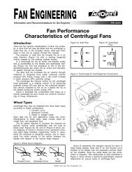
FAN ENGINEERING<br />
®<br />
Information and Recommendations for the Engineer<br />
FE-2700<br />
<strong>Direct</strong> <strong>Drive</strong> <strong>Fan</strong> <strong>Selection</strong>s<br />
Introduction<br />
<strong>Direct</strong> drive fans are usually specified because, under<br />
the right circumstances, they offer the user the most<br />
compact, lowest cost and lowest maintenance fan available.<br />
They also have fewer sources of vibration and are<br />
often used where very low levels of vibration is a<br />
requirement. However, because the fan speeds are limited<br />
to available motor speeds, the number of selections<br />
are limited, and may not be at maximum impeller efficiency.<br />
Also, because of the limited motor speeds available,<br />
a direct drive fan may require selecting a more<br />
expensive lower speed motor to meet the performance<br />
requirements.<br />
The actual final operating RPM of the motor varies<br />
with motor design and the power required to drive the<br />
fan. Typical operating speeds are given in Table 1.<br />
Motors greater than 8 pole are rarely used in fans.<br />
Inverter drives make speed selections for direct drive<br />
fans as flexible as belt drive fans. This significantly<br />
increases the overall installed first cost, however this<br />
cost may be offset by the ability to reduce the fan<br />
speed when full flow is not required. This article will be<br />
restricted to the mechanics of matching an axial or<br />
centrifugal fan to constant motor speeds.<br />
Axial <strong>Fan</strong>s<br />
Typically, direct drive fan performance for cast fixed<br />
pitch propellers is presented in tabular form similar to<br />
that shown in Table 2.<br />
For a given fan diameter, the tables are set up to<br />
cover a set range of performance at available motor<br />
horsepower and speed. An assortment of propellers having<br />
different numbers of blades, different pitch settings<br />
or design style may be used to match up performance<br />
with specific motor horsepower and speed. Since the<br />
number of selections available in the table are limited,<br />
it is unlikely that any of the offerings will exactly satisfy<br />
the performance requirements. Accordingly, either the<br />
requirements must be relaxed or a non standard fan<br />
must be selected.<br />
While it is not practical for a fan manufacturer to<br />
publish all available fan curve data in their catalogs, they<br />
more than likely have additional performance information<br />
available in the form of a computer selection program.<br />
For example: Select a 24" diameter propeller fan to<br />
deliver 8200 CFM at 1 ⁄4" SP.<br />
From Table 2 we can find two selections, that while<br />
close, do not exactly satisfy the performance requirements.<br />
A model 24L230 propeller shows a performance<br />
Table 1. Operating Speeds<br />
NOMINAL RPM NUMBER USABLE RPM RANGE<br />
60 Hz 50 Hz OF POLES 60 Hz 50 Hz<br />
3600 3000 2 3450 - 3580 2875 - 2980<br />
1800 1500 4 1725 - 1790 1435 - 1490<br />
1200 1000 6 1140 - 1190 950 - 990<br />
900 750 8 850 - 890 710 - 740<br />
Table 2. Fixed Pitch Propeller <strong>Fan</strong> Performance<br />
CATALOG NUMBER<br />
CUBIC FEET PER MINUTE & HORSEPOWER AT STATIC PRESSURE<br />
0" SP 1/8" SP 1/4" SP 3/8" SP 1/2" SP 3/4" SP 1" SP 1 1 ⁄4" SP 1 1 ⁄2" SP<br />
PROP<br />
FAN<br />
TYPE<br />
RPM HP CFM BHP CFM BHP CFM BHP CFM BHP CFM BHP CFM BHP CFM BHP CFM BHP CFM BHP<br />
24L232 DDP 1160 1/3 6110 .350 5100 .350 3200 .310<br />
24L428 DDP 1160 1/2 6790 .460 6150 .500 5370 .510 4350 .510<br />
24L432 DDP 1160 3/4 7550 .610 6900 .610 6100 .600 5050 .620<br />
24L220 DDP 1750 1/2 7070 .530 6440 .570 5700 .570 4850 .580 3790 .560<br />
24L225 DDP 1750 3/4 8100 .800 7450 .820 6750 .830 5930 .820 4890 .800<br />
24L420 DDP 1750 1 8020 .870 7600 .930 7190 .970 6750 1.00 6240 1.02 4950 1.07<br />
24L230 DDP 1750 1 8950 1.09 8320 1.10 7650 1.10 6900 1.09 5710 1.02<br />
24L426 DDP 1750 1 1 ⁄2 9680 1.38 9350 1.41 8880 1.46 8450 1.50 7950 1.53 6700 1.57<br />
24L432 DDP 1750 2 11400 2.05 10950 2.05 10500 2.04 10000 2.04 9500 2.03 8300 2.07 6100 2.03<br />
24S726 DDP 1160 1/2 6410 .390 5920 .430 5340 .470 4480 .500<br />
24S728 DDP 1160 3/4 6710 .490 6220 .530 5620 .560 4800 .500<br />
24S719 DDP 1750 1 7440 .780 7150 .890 6820 .900 6480 .960 6100 1.01 5110 1.09 3350 1.08<br />
©2003 Twin City <strong>Fan</strong> Companies, Ltd.
of 7650 CFM at 1 ⁄4" SP with a 1750 RPM, 1 HP motor,<br />
which is less than our requirement, and a model 24L426<br />
propeller that shows a performance of 8880 CFM at 1 ⁄4"<br />
SP with a 1750 RPM, 1 1 ⁄2" HP motor, which is more<br />
than our requirement.<br />
Should a computer generated curve be available, we<br />
can see that the model 24L230 propeller actually results<br />
in 7780 CFM at 0.225" SP and 1.11 BHP (Figure 1) and<br />
the model 24L426 propeller would deliver 8760 CFM at<br />
0.29" SP and 1.48 BHP (Figure 2).<br />
If these selections are not close enough, it may be<br />
possible by interpolation in the performance table or<br />
through the computer program, to select a different<br />
propeller that may meet or come very close to meeting<br />
the design performance.<br />
For example: If we were to plot out multiple angle<br />
(pitch) curves for the 24L4 propeller (Figure 3) it can be<br />
seen that a 24L424 propeller comes very close to meeting<br />
the design performance of 8200 CFM at 1 ⁄4" SP. The<br />
intersection of the 24 degree performance curve and the<br />
system curve results in an actual performance of 8300<br />
CFM at 0.26" SP with 1.3 BHP.<br />
With the wonders of the computer, this looks to be<br />
the ideal selection; however, as stated previously in the<br />
article, we are dealing with fixed pitch cast propellers.<br />
It would be best to check with the factory to see if this<br />
particular propeller is available with that blade pitch.<br />
Manually adjustable pitch propellers, where available,<br />
offer the user more flexibility than a cast solid propeller,<br />
in selecting a direct drive fan and has the added advantage<br />
of being field adjustable should the need arise.<br />
We can also increase the number of direct drive<br />
selections by using different speed motors and/or changing<br />
the propeller diameter. These can have advantages<br />
and disadvantages. By selecting a 2 pole (3500 RPM)<br />
motor we can reduce the overall fan cost by using a<br />
lower cost motor and a smaller diameter fan, but at a<br />
higher sound level. Conversely, by selecting a 6 pole<br />
(1160 RPM) motor we can decrease the sound level at<br />
the expense of a higher cost motor and a larger diameter<br />
fan.<br />
Because the motor on a direct drive axial fan is<br />
located in the airstream, its ability to handle hot and/or<br />
contaminated air is severely limited when compared to<br />
belt driven fans. Typically a direct drive axial fan is<br />
limited to 104°F air temperature. By using a motor with<br />
class H insulation, the next larger size horsepower, high<br />
temperature grease and breather pipes, a direct drive<br />
fan can be made suitable for temperatures to 275°F.<br />
Centrifugal <strong>Fan</strong>s<br />
The most common method used to select direct drive<br />
performance for a centrifugal fan is to change the fan<br />
blade width. Backward inclined fans have an allowable<br />
blade width range from 50 to 105%. For a given RPM<br />
and SP the CFM and BHP reduction/increase is proportional<br />
to the percentage reduction/increase in the blade<br />
width.<br />
Centrifugal fan performance data is normally presented<br />
in catalogs in what are referred to as “blower<br />
tables” (Table 3), and is not as user friendly as performance<br />
curves when selecting direct drive performance,<br />
because the data is presented at random speeds and<br />
not specific motor speeds.<br />
For example: Select a fan from Table 3 to deliver<br />
12000 CFM at 3" SP using a 1750 RPM motor.<br />
Inspection of the 3" SP column indicates that we<br />
need to interpolate between 1710 RPM and 1884 RPM<br />
to obtain the base line performance at 1750 RPM.<br />
STATIC PRESSURE (in. w.g.)<br />
Figure 1. 24L230 Performance Curve<br />
0.9<br />
0.8<br />
0.7<br />
0.6<br />
0.5<br />
0.4<br />
0.3<br />
0.2<br />
0.1<br />
SP@1750 RPM<br />
SYSTEM<br />
CURVE<br />
CATALOG<br />
RATING<br />
BHP@1750 RPM<br />
OPERATING<br />
POINT<br />
1 2 3 4 5 6 7 8<br />
CFM (IN 1,000s)<br />
Figure 2. 24L426 Performance Curve<br />
STATIC PRESSURE (in. w.g.)<br />
1.8<br />
1.6<br />
1.4<br />
1.2<br />
1.0<br />
0.8<br />
0.6<br />
0.4<br />
0.2<br />
SP@1750 RPM<br />
SYSTEM<br />
CURVE<br />
DESIGN<br />
POINT<br />
1.35<br />
1.20<br />
1.05<br />
0.90<br />
0.75<br />
0.60<br />
0.45<br />
0.30<br />
0.15<br />
BHP@1750 RPM 1.6<br />
OPERATING<br />
POINT<br />
CATALOG<br />
RATING<br />
DESIGN<br />
POINT<br />
1.5 3.0 4.5 6.0 7.5 9.0 10.5 12.0<br />
CFM (IN 1,000s)<br />
Figure 3. 24L424 Performance Curve<br />
STATIC PRESSURE (in. w.g.)<br />
1.20<br />
1.05<br />
0.90<br />
0.75<br />
0.60<br />
0.45<br />
0.30<br />
0.15<br />
1.5 3.0<br />
24<br />
23<br />
22<br />
23<br />
22 24<br />
25<br />
26<br />
OPERATING<br />
POINT<br />
DESIGN<br />
POINT<br />
SP@ANGLE<br />
SYSTEM<br />
CURVE<br />
BHP@ANGLE<br />
4.5 6.0 7.5 9.0 10.5 12.0<br />
CFM (IN 1,000s)<br />
25<br />
26<br />
1.8<br />
1.4<br />
1.2<br />
1.0<br />
0.8<br />
0.6<br />
0.4<br />
0.2<br />
1.6<br />
1.4<br />
1.2<br />
1.0<br />
0.8<br />
0.6<br />
0.4<br />
0.2<br />
BRAKE HORSEPOWER<br />
BRAKE HORSEPOWER<br />
BRAKE HORSEPOWER<br />
2 <strong>Fan</strong> Engineering FE-2700
Table 3. Backward Inclined Centrifugal <strong>Fan</strong> Performance<br />
WHEEL DIAMETER = 27.95 in. OUTLET AREA = 4.49 ft 2<br />
WHEEL CIRCUMFERENCE = 7.32 ft. MAX. BHP = 4.60 (RPM÷1000) 3<br />
CFM OV<br />
0.5" SP 1" SP 2" SP 3" SP 4" SP 5" SP 6" SP 7" SP 8" SP<br />
RPM BHP RPM BHP RPM BHP RPM BHP RPM BHP RPM BHP RPM BHP RPM BHP RPM BHP<br />
4490 1000 493 0.55 604 0.99<br />
6735 1500 653 1.15 722 1.71 868 2.98 1016 4.45<br />
8980 2000 826 2.18 882 2.89 986 4.40 1094 6.07 1208 7.88 1319 9.86 1427 12.03<br />
11225 2500 1006 3.80 1053 4.64 1139 6.44 1222 8.35 1308 10.39 1396 12.56 1487 14.81 1577 17.18 1665 19.74<br />
13470 3000 1190 6.14 1230 7.13 1305 9.20 1374 11.37 1444 13.69 1515 16.07 1587 18.57 1660 21.16 1735 23.82<br />
15715 3500 1375 9.32 1410 10.47 1477 12.84 1540 15.32 1599 17.87 1658 20.53 1718 23.25 1780 26.11 1841 28.98<br />
17960 4000 1562 13.52 1593 14.82 1653 17.50 1710 20.25 1764 23.09 1816 26.02 1867 29.00 1919 32.07 1973 35.27<br />
20205 4500 1750 18.88 1778 20.34 1832 23.31 1884 26.36 1934 29.48 1981 32.64 2027 35.90 2073 39.26 2119 42.69<br />
22450 5000 1939 25.54 1964 27.14 2013 30.41 2060 33.73 2106 37.13 2151 40.62 2194 44.17 2236 47.80 2277 51.47<br />
24695 5500 2128 33.62 2151 35.39 2195 38.91 2239 42.57 2282 46.29 2324 50.08 2364 53.87 2404 57.81 2442 61.75<br />
26940 6000 2317 43.26 2338 45.17 2379 49.03 2420 53.00 2460 57.02 2499 61.10 2537 65.21 2574 69.36 2610 73.58<br />
CFM OV<br />
9" SP 10" SP 11" SP 12" SP 13" SP 14" SP 16" SP 18" SP 20" SP<br />
RPM BHP RPM BHP RPM BHP RPM BHP RPM BHP RPM BHP RPM BHP RPM BHP RPM BHP<br />
4490 1000<br />
6735 1500<br />
8980 2000<br />
11225 2500 1751 22.42 1836 25.28<br />
13470 3000 1812 26.61 1887 29.48 1960 32.48 2033 35.64 2104 38.87 2175 42.28<br />
15715 3500 1904 32.01 1967 35.06 2032 38.21 2097 41.40 2162 44.71 2226 48.15 2351 55.35 2474 62.97 2594 70.98<br />
17960 4000 2026 38.47 2080 41.78 2134 45.14 2189 48.61 2245 52.15 2301 55.68 2415 63.00 2528 70.72 2638 78.85<br />
20205 4500 2166 46.19 2213 49.72 2261 53.37 2308 56.99 2356 60.73 2405 64.60 2503 72.45 2603 80.43 2705 88.72<br />
22450 5000 2318 55.20 2360 59.06 2402 62.93 2444 66.82 2487 70.83 2530 74.89 2616 83.14 2703 91.65 2792 100.46<br />
24695 5500 2479 65.71 2517 69.84 2554 73.94 2592 78.17 2630 82.40 2669 86.75 2746 95.45<br />
26940 6000 2646 77.93 2680 82.20 2715 86.66 2749 91.09 2783 95.58<br />
(1) 1884 RPM – 1710 RPM = 174 RPM<br />
1750 RPM – 1710 RPM = 40 RPM<br />
40 RPM ÷ 174 RPM = 0.23 ratio<br />
(2) baseline CFM =<br />
(20205 CFM – 17960 CFM) 0.23 + 17960 CFM = 18476 CFM<br />
(3) baseline BHP =<br />
(26.36 BHP – 20.25 BHP) 0.23 + 20.25 BHP = 21.66 BHP<br />
(4) design CFM ÷ baseline CFM = wheel blade width %<br />
12000 CFM ÷ 18476 CFM = 0.649 or a 65% blade width<br />
(5) BHP at 65% blade width =<br />
21.66 BHP x 0.65 = 14.08 BHP<br />
After all this we know that a 28" backward inclined<br />
centrifugal fan with a 65% wheel width will deliver 12000<br />
CFM at 3" SP at 1750 RPM and will require 14.08 BHP.<br />
But is this the best selection It’s difficult to tell from<br />
the data. We would have to repeat this process for other<br />
size fans to know for sure.<br />
Computer generated curves (when available) provide<br />
a much easier selection process. Figure 4 shows the<br />
performance curve of this same 28" backward inclined<br />
centrifugal fan at 1750 RPM.<br />
Reading horizontally from left to right, we intersect<br />
the performance curve at 18500 CFM.<br />
(4) 12000 CFM / 18500 CFM = 0.649 or a 65% blade width<br />
With a few simple key strokes we input the 65%<br />
blade width in the space provided and produce the fan<br />
curve as shown in Figure 5.<br />
An inspection of this curve indicates we would be<br />
better served with a smaller fan. With the computer we<br />
can easily click back to a 100% blade width and then<br />
click on the next smaller size fan, and see that it<br />
matches our requirements rather nicely (Figure 6).<br />
The 25" diameter fan performance shown in Figure 6<br />
gives us the choice of using a 96% blade width to<br />
exactly match the design point of 12000 CFM at 3" SP,<br />
or we can accept a slightly higher operating performance<br />
of 12400 CFM at 3.2" SP, and avoid the added cost of<br />
narrow width construction. In addition, the 25" diameter<br />
fan costs less, has a higher operating efficiency and has<br />
a significantly lower sound level than the 28” diameter<br />
fan.<br />
Figure 4. 28" – 100% Width BI Centrifugal Performance Curve<br />
STATIC PRESSURE (in. w.g.)<br />
12.0<br />
10.5<br />
9.0<br />
7.5<br />
6.0<br />
4.5<br />
3.0<br />
1.5<br />
13.5<br />
12.0<br />
10.5<br />
9.0<br />
7.5<br />
6.0<br />
4.5<br />
1.5<br />
SP@1750 RPM<br />
SP@1750 RPM<br />
DESIGN<br />
POINT<br />
BHP@1750 RPM<br />
BASE LINE<br />
CFM<br />
4 8 12 16 20 24<br />
CFM (in 1000s)<br />
Figure 5. 28" – 65% Width BI Centrifugal Performance Curve<br />
STATIC PRESSURE (in. w.g.)<br />
3.0<br />
BHP@1750 RPM<br />
DESIGN<br />
POINT<br />
2 4 6 8 10 12 14 16<br />
CFM (in 1000s)<br />
32<br />
28<br />
24<br />
20<br />
16<br />
12<br />
8<br />
4<br />
18<br />
16<br />
14<br />
12<br />
10<br />
8<br />
6<br />
4<br />
2<br />
BRAKE HORSEPOWER<br />
BRAKE HORSEPOWER<br />
3 <strong>Fan</strong> Engineering FE-2700
Should we decide to use the 28" diameter fan selection,<br />
it would be necessary to adjust the fan housing<br />
width to be compatible with the narrow width wheel<br />
construction. To accomplish this, we would need to<br />
know both the 100% blade and housing widths. For this<br />
particular fan the wheel blade width is 10 1 ⁄16" and the<br />
housing width is 21 3 ⁄32".<br />
The new blade width = 10 1 ⁄16" x 0.65 = 6.54" or 6 9 ⁄16"<br />
The new housing width = 21 3 ⁄32" – (10 1 ⁄16" – 6 9 ⁄16") =<br />
17 19 ⁄32"<br />
A new housing outlet area can be approximated by<br />
multiplying the standard housing outlet area (Table 2) by<br />
the ratio of the narrow to standard housing width.<br />
Outlet area (new) =<br />
outlet area (old) x housing width (new) ÷ housing width<br />
(old)<br />
= 4.49 ft 2 (17 19 ⁄32" ÷ 21 3 ⁄32") = 3.74 ft 2<br />
If the 25" diameter fan was our choice, no housing<br />
width adjustment would be required because even if we<br />
selected the 96% wheel width, housing widths are generally<br />
not adjusted until the blade width reduction is<br />
greater than one inch.<br />
Narrow width construction is by far the best “low<br />
cost” method, for maximizing the number of direct drive<br />
centrifugal fan selections. Within a narrow range of limits,<br />
for a given size, the wheel diameter can be increased<br />
or decreased, usually only by 5%. <strong>Selection</strong> by varying<br />
the wheel diameter requires the use of computerized<br />
selection program.<br />
Other methods could include varying the number, the<br />
chord width or chord angle of the blades, but this<br />
involves methodology beyond the scope of this article.<br />
AMCA Spark Resistant<br />
Construction<br />
Arrangement 4 centrifugal fans can be made to satisfy<br />
AMCA type “A,” type “B,” and type “C” construction. It<br />
may require a special motor shaft to allow for better<br />
sealing around the housing shaft opening. AMCA type<br />
“A” spark resistant construction requires completely<br />
enclosing the motor shaft, which protrudes inside the fan<br />
housing.<br />
Arrangement 4 plenum fans do not comply with any<br />
fan spark resistant standards, since the lack of a fan<br />
housing forces the motor bearings to be in the airstream.<br />
Some applications have used explosion proof<br />
motors to reduce the risk of explosion.<br />
Arrangement 8 construction should be considered for<br />
direct drive applications whenever possible. The bearings<br />
can be located away from the housing to accommodate<br />
better seals. Arrangement 7 direct drive fans are not<br />
allowed because of the bearing(s) in the airstream.<br />
Figure 6. 25" – 100% Width BI Centrifugal Performance Curve<br />
STATIC PRESSURE (in. w.g.)<br />
8<br />
7<br />
6<br />
5<br />
4<br />
3<br />
2<br />
1<br />
SP@1750 RPM<br />
DESIGN<br />
POINT<br />
SYSTEM<br />
CURVE<br />
BHP@1750 RPM<br />
100% WIDTH<br />
OPERATING<br />
POINT<br />
BASELINE<br />
CFM<br />
2 4 6 8 10 12 14 16<br />
CFM (in 1000s)<br />
High Temperature Construction<br />
Arrangement 4 centrifugal fans are typically limited to<br />
180°F. However, temperatures to 275°F are attainable<br />
using special class H insulated motors. <strong>Direct</strong> drive<br />
selections above 275°F will be limited to Arrangement 8<br />
construction. Arrangement 7 direct drive fans without inlet<br />
boxes are limited to 200°F maximum temperatures.<br />
Corrosion Resistant Construction<br />
Arrangement 4 centrifugal fans for corrosive applications<br />
face similar problems as encountered with spark resistant<br />
fans. Special shaft materials that resist corrosion or<br />
enclosing the motor shaft with a corrosive resistant<br />
sleeve may be required. Special length shafts for mounting<br />
shaft seals may be required along with adding thrust<br />
vanes to the backside of the impeller to help prevent<br />
corrosives from leaking out the shaft hole in the fan<br />
housing. As with the spark resistant fans, arrangement<br />
8 should be the construction of choice. Arrangement 7<br />
construction can be used, but only with an inlet box.<br />
Conclusion<br />
This article has covered but a few of the different types<br />
of axial and centrifugal fans that are available or that<br />
can be adapted to direct drive applications. Each fan<br />
type may have its own special rules, limitations or considerations<br />
for direct drive construction, but the methodology<br />
described herein remains the same.<br />
A word of caution: special construction for direct<br />
drive fans such as high temperature applications, corrosive<br />
applications or spark resistant applications should<br />
always be confirmed through the factory.<br />
16<br />
14<br />
12<br />
10<br />
8<br />
6<br />
4<br />
2<br />
BRAKE HORSEPOWER<br />
®<br />
<strong>Aerovent</strong> | www.aerovent.com<br />
5959 Trenton Lane N | Minneapolis, MN 55442 | Phone: 763-551-7500 | Fax: 763-551-7501