AUTOSAR - KPIT
AUTOSAR - KPIT
AUTOSAR - KPIT

You also want an ePaper? Increase the reach of your titles
YUMPU automatically turns print PDFs into web optimized ePapers that Google loves.
MBD<br />
CAN<br />
ASIL Decomposition<br />
ISO 14229<br />
Bootloader<br />
Gateway<br />
MCD3 API<br />
Optimization<br />
Scalablility<br />
Migration<br />
Training<br />
MBD<br />
Testing CoE<br />
CAN<br />
LIN<br />
DoIP<br />
Complex<br />
Drivers<br />
MCD3 API<br />
Complex<br />
Drivers<br />
Validation<br />
Consulting<br />
ISO 14229<br />
<strong>AUTOSAR</strong> Handbook<br />
<strong>KPIT</strong> Technologies Ltd.<br />
Validation R 3.x ASAM HIS-MISRA<br />
Standardization<br />
Migration COMR4.x<br />
Microlayer driversVCI<br />
CAN<br />
RTE generation<br />
Migration R 3.x ARTOP<br />
Customizable<br />
MBD Consulting<br />
HIS-MISRA<br />
eNOS Partner Testing<br />
Testing CoE<br />
MCAL<br />
BSW stack Configuration<br />
In-vehicle network<br />
OSEK R 3.x<br />
ECU<br />
R 3.x<br />
Training<br />
Validation Tool chain Gateway<br />
Mode<br />
ISO 14229<br />
R 4.x<br />
Partial<br />
Migration<br />
Standardization<br />
MBD<br />
Network<br />
R 3.x drivers<br />
OSEK<br />
Management Network Management<br />
MBD<br />
VCI<br />
OSEK<br />
CT Specs<br />
Management<br />
OTX Networking CT-Spec Network Consulting<br />
ASAM<br />
Hazard Analysis MCD3 APIGateway<br />
<strong>AUTOSAR</strong> ASAM<br />
Hardware<br />
ECU <strong>AUTOSAR</strong> Tool chain Training Management MBD FUNCTIONAL SAFETY<br />
ASAM TrainingVCI<br />
MBD ASAM Optimization<br />
Tool qualification MBD<br />
Validation<br />
Tool qualification Network<br />
Management<br />
CT Specs<br />
eNOS<br />
MBD<br />
In-vehicle network drivers ECU<br />
HardwareASAM<br />
ASIL A, B, C, D<br />
ECU<br />
Migration Validation Partial ISO 15765 Mode<br />
MCAL<br />
MBD<br />
Scalablility<br />
ManagementMBD<br />
Adaptation<br />
Validation<br />
ECU<br />
SpecificationsTesting<br />
Validation<br />
Partial Networking<br />
CAE Risk Assessment<br />
In-vehicle<br />
OSEK hardware MBD<br />
MCD3 API<br />
CT Specs<br />
MCAL Networking Testing Optimization<br />
eNOS<br />
CT BSW Stack<br />
R 4.x ECU<br />
Production Ready<br />
ASAM ISO 14229<br />
Testing<br />
network R 3.x ODX<br />
MBD<br />
BSW stack ISO 26262<br />
MBD<br />
Frugal drivers<br />
ECU<br />
PDU Gateway<br />
R 4.x<br />
porting<br />
CT Specs drivers<br />
RouterASAM<br />
MCD3 API<br />
Bootloader Production Ready DIAGNOSTICS<br />
Engineering ECU<br />
Validation<br />
eNOS<br />
Migration<br />
VCI LIN<br />
ODX <strong>AUTOSAR</strong> OSEK hardware<br />
Tool chain Mode Management Training ISO 26262<br />
Validation<br />
ECU<br />
<strong>AUTOSAR</strong><br />
SpecificationseNOS<br />
Legacy to MBD BSW Stack<br />
Training Configuration<br />
NETWORK<br />
ISO 15765<br />
Migration<br />
Validation Hardware<br />
OSEK Legacy to MBD MBD<br />
Microlayer ECU<br />
hardware<br />
ASAM Portability Migration<br />
CT-Spec<br />
hardware<br />
Mode Management<br />
MANAGEMENT<br />
ISO26262 HIS-MISRA Hardware Diagnostics MBD ASAM Validation Network Management<br />
Board Support<br />
eNOS<br />
ECU<br />
Diagnostics<br />
OTX Production<br />
Efficient<br />
Package<br />
CT-Spec<br />
Ready<br />
Scalablility<br />
LIN<br />
Testing<br />
R 4.x<br />
ODX Customizable<br />
VCI<br />
Risk Assessment Optimization<br />
Diagnostics &<br />
ECU<br />
Consulting<br />
drivers<br />
FUNCTIONAL SAFETY<br />
Complex<br />
HIS-MISRA<br />
Drivers Tool chain<br />
ODX<br />
Gateway<br />
Consulting<br />
DoIP<br />
Network Management<br />
Training<br />
eNOS Scalablility<br />
PC Tools<br />
ECU<br />
Gateway Hazard Analysis Validation CT<br />
Remote Diagnostic<br />
Consulting<br />
R3.x SCALABLILITY<br />
Validation<br />
ODX<br />
Toolchain Testing CoE<br />
Partial<br />
DoIP<br />
ASIL Decomposition<br />
CT-Spec<br />
<strong>AUTOSAR</strong> CT-Spec MBD ASAM<br />
ISO 26262<br />
ISO 15765<br />
HIS-MISRA<br />
OSEK<br />
Networking<br />
Testing CoE<br />
porting<br />
Complex Drivers COM<br />
Hardware BSW stack<br />
ASAM<br />
Bootloader<br />
Training<br />
ASAM<br />
ECU eNOS<br />
ASAM VCI ASIL Decomposition<br />
DoIP ARTOP<br />
MBD<br />
Partial Networking<br />
Risk Assessment Mode Management<br />
Migration OTX<br />
BSW Stack<br />
Gateway<br />
Aftertreatment<br />
VCI<br />
Microlayer<br />
R4.xPartial Networking<br />
Tool<br />
FUNCTIONAL SAFETY<br />
Optimization<br />
Consulting<br />
porting<br />
MBD<br />
Efficient<br />
CT-Spec<br />
ECU<br />
BSW Stack<br />
Migration DoIP<br />
Qualification<br />
ARTOP DIAGNOSTICS hardware<br />
Tool Qualification<br />
ASIL A, B, C, D<br />
Mode<br />
MCAL<br />
OSEK MBD ASAM<br />
Customizable<br />
<strong>AUTOSAR</strong><br />
DoIP<br />
Hazard Analysis<br />
Validation FUNCTIONAL SAFETY Powerseat ECULIN<br />
Risk Assessment<br />
drivers ODX<br />
ISO 26262<br />
eNOS<br />
MBD<br />
Management ECU Risk Assessment Bootloader<br />
ECU<br />
Validation<br />
ECU RTE generation Error handling<br />
<strong>AUTOSAR</strong><br />
<strong>AUTOSAR</strong><br />
COM<br />
Consulting<br />
CT-Spec OSEK<br />
PDU Router<br />
ODX<br />
Production Ready MCAL<br />
CT-Spec<br />
ISO 15765<br />
ISO 15765<br />
Power Window Bootloader<br />
Network Management Validation<br />
porting MCD3 API<br />
Scalablility<br />
MCD3 API Development<br />
COM<br />
Tool Qualification<br />
Error handling<br />
Training<br />
CAN<br />
ASAM<br />
LIN<br />
R4.x ODX<br />
ISO 15765<br />
FUNCTIONAL<br />
CT-Spec Production Ready<br />
HIS-MISRA<br />
Gateway<br />
Portability Configuration<br />
SAFETY LIN<br />
ODX<br />
ISO 14229<br />
Validation OSEK Scalability<br />
ODX<br />
Gateway<br />
ARTOP<br />
CAN<br />
<strong>AUTOSAR</strong> Handbook<br />
© <strong>KPIT</strong> Technologies Ltd.
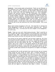
<strong>AUTOSAR</strong> Solutions<br />
A Premium Member of <strong>AUTOSAR</strong> consortium since 2005, <strong>KPIT</strong> provides products and<br />
services for the various layers of <strong>AUTOSAR</strong> stack for OEMs, Tier1s, and Semiconductor<br />
ODMs (Original Design Manufacturers). Actively involved in the automotive standardization<br />
across the globe, we help customers at every stage of their <strong>AUTOSAR</strong> development through<br />
end-to-end <strong>AUTOSAR</strong> Tool chain in association with leading industry Tool Suppliers.<br />
<strong>AUTOSAR</strong> Handbook<br />
[ II ]<br />
© <strong>KPIT</strong> Technologies Ltd.
Contents<br />
Part 1<br />
1.1<br />
1.2<br />
1.3<br />
1.4<br />
1.5<br />
1.6<br />
Part 2<br />
Part 3<br />
Part 4<br />
4.1<br />
Part 5<br />
Part 6<br />
6.1<br />
Introduction to <strong>AUTOSAR</strong><br />
<strong>AUTOSAR</strong><br />
<strong>AUTOSAR</strong> Layer Model<br />
Design and Communication of<br />
Software Components<br />
<strong>AUTOSAR</strong> Method<br />
<strong>AUTOSAR</strong> Interfaces<br />
<strong>AUTOSAR</strong> Basic software Module<br />
Description of <strong>AUTOSAR</strong> work<br />
process and activities<br />
Description of <strong>AUTOSAR</strong> Basic<br />
Software Module (BSW)<br />
<strong>AUTOSAR</strong> System Services<br />
<strong>AUTOSAR</strong> OS<br />
MCAL Solutions<br />
Multicore Support<br />
Introduction<br />
01<br />
02<br />
04<br />
06<br />
08<br />
09<br />
10<br />
11<br />
17<br />
27<br />
28<br />
33<br />
41<br />
42<br />
Part 7<br />
7.1<br />
7.2<br />
Part 8<br />
8.1<br />
8.2<br />
8.3<br />
8.4<br />
8.5<br />
Part 9<br />
9.1<br />
9.2<br />
9.3<br />
Functional Safety<br />
Introduction<br />
<strong>AUTOSAR</strong> Architecture & Safety<br />
Implementation in R4.0<br />
ECU Spectrum Toolchain<br />
Introduction<br />
Inputs used<br />
Outputs Generated<br />
ECU Spectrum Features<br />
Terms used<br />
About <strong>KPIT</strong><br />
<strong>KPIT</strong> <strong>AUTOSAR</strong> Expertise<br />
<strong>KPIT</strong> Advantages<br />
Software Services / Products<br />
Provided by <strong>KPIT</strong><br />
45<br />
46<br />
47<br />
53<br />
54<br />
55<br />
55<br />
60<br />
61<br />
63<br />
64<br />
65<br />
67<br />
<strong>AUTOSAR</strong> Handbook<br />
[ III ]<br />
© <strong>KPIT</strong> Technologies Ltd.
Part 1<br />
Introduction to <strong>AUTOSAR</strong><br />
<strong>AUTOSAR</strong> Handbook<br />
1<br />
© <strong>KPIT</strong> Technologies Ltd.
<strong>AUTOSAR</strong><br />
Automotive Industry coping up with increasing complexity<br />
The in-vehicle systems are becoming more and more complex day in and day out. Today’s hardware<br />
and component-driven development process is becoming more and more requirement and<br />
functional-driven. Future engineering does not aim at optimizing single components but optimizing<br />
on system level which requires an open architecture as well as scalable and exchangeable software<br />
modules.<br />
<strong>AUTOSAR</strong> (AUTomotive Open System ARchitecture), a worldwide consortium of OEMs, suppliers and<br />
other companies, founded in 2003, have been working on the development and introduction of an<br />
open and standardized software architecture for the automotive industry.<br />
To reduce development effort and improve quality are important reasons for introducing a uniform<br />
procedure independent of system platform. Hardware and software are decoupled from one another<br />
to assure such results.<br />
The <strong>AUTOSAR</strong> concept is based on modular components with defined interfaces.<br />
<strong>AUTOSAR</strong> Handbook<br />
2<br />
© <strong>KPIT</strong> Technologies Ltd.
<strong>AUTOSAR</strong><br />
Software<br />
Component<br />
Application<br />
Software<br />
Component<br />
<strong>AUTOSAR</strong><br />
Interface<br />
Actuator<br />
Software<br />
Component<br />
<strong>AUTOSAR</strong><br />
Interface<br />
Sensor<br />
Software<br />
Component<br />
<strong>AUTOSAR</strong><br />
Interface<br />
<strong>AUTOSAR</strong><br />
Software<br />
..............<br />
<strong>AUTOSAR</strong> Runtime Environment (RTE)<br />
Application<br />
Software<br />
Component<br />
<strong>AUTOSAR</strong><br />
Interface<br />
Interface<br />
Standard<br />
Software<br />
Interfaces:<br />
VFB & RTE<br />
relevant<br />
RTE<br />
relevant<br />
BSW<br />
relevant<br />
Possible interfaces<br />
inside<br />
Basic Software<br />
(which are<br />
not specified<br />
within <strong>AUTOSAR</strong>)<br />
Standardized<br />
Interface<br />
Operating<br />
System<br />
Standardized<br />
Interface<br />
Standardized<br />
<strong>AUTOSAR</strong><br />
Interface<br />
Services<br />
Standardized<br />
Interface<br />
Standardized<br />
Interface<br />
Communication<br />
Standardized<br />
Interface<br />
Basic Software<br />
ECU-Hardware<br />
<strong>AUTOSAR</strong><br />
Interface<br />
ECU<br />
Abstraction<br />
Standardized<br />
Interface<br />
Standardized<br />
Interface<br />
Microcontroller<br />
Abstraction<br />
<strong>AUTOSAR</strong><br />
Interface<br />
Complex<br />
Device<br />
Drivers<br />
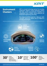
Figure 1: Simplified Component View<br />
<strong>AUTOSAR</strong> Handbook<br />
3<br />
© <strong>KPIT</strong> Technologies Ltd.
<strong>AUTOSAR</strong> Layer Model<br />
In <strong>AUTOSAR</strong>, the ECU software is abstracted and sub-classified as software (BSW) layer, runtime<br />
environment (RTE) and application layer.<br />
The Microcontroller Abstraction Layer contains internal drivers, which are software modules with<br />
direct access to the micro controller and internal peripherals.<br />
The ECU Abstraction Layer offers uniform access to all features of an ECU like communication,<br />
memory or I/O, no matter if these features are part of the microcontroller or realized by peripheral<br />
components. The drivers for such external peripheral components reside in this layer.<br />
The Service Layer provides various types of background services such as vehicle network<br />
communication and management services, diagnostic services, memory management, ECU state<br />
management, mode management and Logical and temporal program flow monitoring. The operating<br />
system is also part of this layer.<br />
The RTE integrates the application layer with the BSW. It implements the data exchange and controls<br />
the integration between the application software component (SWCs) and BSW.<br />
The Application Layer contains the SWCs, which realize the application functionality of the ECU.<br />
<strong>AUTOSAR</strong> Handbook<br />
4<br />
© <strong>KPIT</strong> Technologies Ltd.
APPLICATION LAYER<br />
RUN TIME ENVIRONMENT<br />
SERVICES<br />
LAYER<br />
ECU ABSTRACTION LAYER<br />
COMPLEX<br />
DRIVERS<br />
MICROCONTROLLER ABSTRACTION<br />
LAYER<br />
MICROCONTROLLER<br />
Figure 2: <strong>AUTOSAR</strong> Layered Architecture<br />
<strong>AUTOSAR</strong> Handbook<br />
5<br />
© <strong>KPIT</strong> Technologies Ltd.
Design and Communication of software Components<br />
A fundamental design concept of <strong>AUTOSAR</strong> is the separation between Application and Infrastructure.<br />
An application in <strong>AUTOSAR</strong> consists of interconnected "<strong>AUTOSAR</strong> Software Components". The<br />
interfaces of each SWC are formally defined. Communication between SWCs takes place chiefly over<br />
two kinds of ports, Client/ Server ports where server is a provider of a service and the client is a user of<br />
a service and Sender/ Receiver ports where a sender distributes information to one or several<br />
receivers in synchronous as well as asynchronous environment. The implementation architecture of<br />
SWC is formally defined in terms of so-called runnable entities. They correspond to procedures and are<br />
executed on a specific event such as a periodic activation or reception of new input value. During<br />
system design phase the SWCs can be integrated with their environment (e.g. hardware, driver, OS, etc)<br />
based on Virtual Functional Bus (VFB). The virtual functional bus is the abstraction of the <strong>AUTOSAR</strong><br />
Software Components interconnections of the entire vehicle.<br />
Once the system of SWCs is deployed to the concrete vehicle network architecture, the RTE and BSW of<br />
involved ECUs realize the communication between the SWC either as ECU-local communication or as<br />
network based communication.<br />
<strong>AUTOSAR</strong> Handbook<br />
6<br />
© <strong>KPIT</strong> Technologies Ltd.
SWC_ECU1 is mapped to ECU1<br />
SWC_ECU2 is mapped to ECU2<br />
SWC-ECU1<br />
SWC-ECU2<br />
Virtual Functional Bus<br />
Sensor<br />
Configure software components based on<br />
communication requirements<br />
<strong>AUTOSAR</strong> ECU1<br />
SWC - ECU1<br />
<strong>AUTOSAR</strong> ECU2<br />
SWC - ECU2<br />
Sensor<br />
Network Path<br />
Figure 3: <strong>AUTOSAR</strong> System Design<br />
<strong>AUTOSAR</strong> Handbook<br />
7<br />
© <strong>KPIT</strong> Technologies Ltd.
<strong>AUTOSAR</strong> Method<br />
The <strong>AUTOSAR</strong> Methods (in <strong>AUTOSAR</strong> specifications also called “Methodology”) describes the<br />
workflow that could be followed – from the system configuration up to the final generation of an<br />
executable for a concrete ECU.<br />
The activities are supported by dedicated <strong>AUTOSAR</strong> tools.<br />
For exchanging work products between such tools <strong>AUTOSAR</strong> defined one comprehensive XML file<br />
format.<br />
The detailed description of <strong>AUTOSAR</strong> work flow please refer Part 2 Description of <strong>AUTOSAR</strong> work prod<br />
& activates of this handbook.<br />
<strong>AUTOSAR</strong> Handbook<br />
8<br />
© <strong>KPIT</strong> Technologies Ltd.
<strong>AUTOSAR</strong> Interfaces<br />
<strong>AUTOSAR</strong> Interfaces are used in defining the ports of software-components and/or BSW modules.<br />
Through these ports, software-components and/or BSW modules can communicate with each other<br />
(Send or receive information or invoke services). <strong>AUTOSAR</strong> makes it possible to implement this<br />
communication between Software-Components and/or BSW modules either locally or via a network.<br />
(Refer figure 1, page 3 of handbook)<br />
The <strong>AUTOSAR</strong> Interface is a generic interface which is derived from the ports of a SWC.<br />
<strong>AUTOSAR</strong> Interfaces are provided by the RTE and serve as interface between SWCs or between<br />
SWCs or between a SWC and the ECU firmware (IO HW and Complex Drivers). Via these<br />
interfaces, a SWC an e.g. read an input value or write an output value.<br />
The Standardized <strong>AUTOSAR</strong> Interface is a particular <strong>AUTOSAR</strong> Interface, which is already<br />
predefined by the <strong>AUTOSAR</strong> standard. Such interfaces are used by the SWCs to access<br />
<strong>AUTOSAR</strong> Services, which are provided by BSW modules of the Service Layer like the ECU<br />
manager or the diagnostic event manager.<br />
The Standardized Interface is an interface, which is predefined by the <strong>AUTOSAR</strong> standard as<br />
API in C language. It is used between BSW module within an ECU, between RTE and Operating<br />
System (OS), or between RTE and the Communication Layer.<br />
<strong>AUTOSAR</strong> Handbook<br />
9<br />
© <strong>KPIT</strong> Technologies Ltd.
<strong>AUTOSAR</strong> Basic Software Module<br />
<strong>AUTOSAR</strong> has defined a set of BSW modules. They are responsible for different tasks:<br />
Operating System<br />
Access to non volatile memory<br />
Communication via CAN, LIN, FlexRay and Ethernet<br />
Handling the diagnostics<br />
Access to I/O ports<br />
System services like ECU state management<br />
In addition, so-called Complex Device Drivers can be integrated into an <strong>AUTOSAR</strong> ECU. They are used<br />
to access the features of the ECU, which are not covered by the standard BSW of <strong>AUTOSAR</strong>.<br />
The detailed description of the BSW module parameters is included in a module specific XML file – the<br />
BSW Module Description (compare to Figure 4 and the table in part 2 of this handbook).<br />
A list of all BSW modules and a short description can be found in the part 3 of this handbook.<br />
<strong>AUTOSAR</strong> Handbook<br />
10<br />
© <strong>KPIT</strong> Technologies Ltd.
Part 2<br />
Description of <strong>AUTOSAR</strong><br />
work products & activities<br />
<strong>AUTOSAR</strong> Handbook<br />
11<br />
© <strong>KPIT</strong> Technologies Ltd.
System<br />
per ECU<br />
API Generator<br />
Component API<br />
SWC Implementation<br />
SWC<br />
Description<br />
System<br />
Configuration<br />
Description<br />
ECU<br />
Configuration<br />
Description<br />
RTE<br />
Generator<br />
ECU<br />
Description<br />
(HW only)<br />
System<br />
Configuration<br />
Generator<br />
ECU extract of<br />
System<br />
Configuration<br />
ECU<br />
Configuration<br />
Generator<br />
RTE Extract<br />
OS Extract<br />
OS, COM<br />
Generator<br />
System<br />
Constraint<br />
Description<br />
ECU extract of<br />
System<br />
Configuration<br />
BSW module<br />
Extract<br />
SWC<br />
Implementation<br />
List<br />
BSW<br />
Generator<br />
MCAL<br />
Generator<br />
Information/Database (no files)<br />
Generation Step: complex algorithm or engineering work<br />
Figure 4: Overview of the <strong>AUTOSAR</strong> method<br />
<strong>AUTOSAR</strong> Handbook<br />
12<br />
© <strong>KPIT</strong> Technologies Ltd.
Information/<br />
activities<br />
System Constraint<br />
System<br />
Configuration<br />
Generator<br />
System<br />
Configuration<br />
Description<br />
Description<br />
These are constraints, which must be considered during system configuration. An<br />
example for such System Constraints is a given (partial) communication matrix<br />
from the last vehicle series, which must not be changed when designing the new<br />
vehicle series.<br />
This activity creates a complete System Description with the necessary SWC<br />
Description and the associated system Communication Matrix. Basis for this<br />
activity are the System Constraints. In addition, this activity requires design<br />
decisions to be made at system level by considering the available ECU and network<br />
resources. This includes the definition of network topology, definition of SWC,<br />
mapping of SWC to ECUs and specification of the network communication.<br />
This includes all system information and the information that must be agreed<br />
between different ECUs including the network topology and the allocation of the<br />
components to the ECUs. A System Description is always completed by the<br />
necessary SWC Descriptions and an associated System Communication Matrix.<br />
SWC Description<br />
This specifies information about an SWC including its ports and runnable entities.<br />
<strong>AUTOSAR</strong> Handbook<br />
13<br />
© <strong>KPIT</strong> Technologies Ltd.
Information/<br />
activities<br />
ECU Extract of<br />
System<br />
Configuration<br />
ECU<br />
configuration<br />
Generator<br />
ECU<br />
Configuration<br />
Description<br />
BSW<br />
Generator<br />
Description<br />
This work product contains information from the System Configuration<br />
Description needed for a specific ECU. It includes the description of the SWCs on<br />
this ECU as well as the subset of the communication matrix relevant for the ECU.<br />
This creates an ECU Configuration Description. Basis is the ECU Extract and the<br />
vendor specific BSW Module Description. In addition, this activity requires design<br />
decisions to be made at ECU level.<br />
This includes setting values for the configurable parameters of all BSW modules<br />
and the RTE, like mapping runnable entities to operating system tasks, defining<br />
the memory layout or configuring the operating system.<br />
This describes all information that is local to a specific ECU the runnable software<br />
can be built from this information and the code of the software component<br />
This activity generates the configurable part of the BSW module of an ECU. Basis<br />
for this generation process is the ECU configuration Description of the ECU. This<br />
activity requires no design decisions.<br />
<strong>AUTOSAR</strong> Handbook<br />
14<br />
© <strong>KPIT</strong> Technologies Ltd.
Information/<br />
activities<br />
BSW extract of ECU<br />
configuration<br />
Description<br />
This describes of all configuration parameters of a particular BSW module,<br />
including vendor specific parameters. This description always reflects a concrete<br />
implementation of the BSW module. Therefore, it is provided by the BSW module<br />
supplier and is not changed during the ECU configuration process.<br />
RTE Generator<br />
This activity generates the RTE of an ECU. This activity requires no design decisions.<br />
<strong>AUTOSAR</strong> Handbook<br />
15<br />
© <strong>KPIT</strong> Technologies Ltd.
[ THIS PAGE INTENTIONALLY LEFT BLANK ]<br />
<strong>AUTOSAR</strong> Handbook<br />
16<br />
© <strong>KPIT</strong> Technologies Ltd.
Part 3<br />
Description of <strong>AUTOSAR</strong><br />
Basic Software Module (BSW)<br />
<strong>AUTOSAR</strong> Handbook<br />
17<br />
© <strong>KPIT</strong> Technologies Ltd.
<strong>AUTOSAR</strong> ECU<br />
APPLICATION LAYER<br />
RUN TIME ENVIRONMENT<br />
SERVICE<br />
LAYER<br />
ECU ABSTRACTION LAYER<br />
MICROCONTROLLER ABSTRACTION<br />
LAYER<br />
COMPLEX<br />
DRIVERS<br />
MICROCONTROLLER<br />
SERVICES<br />
PRODUCTS<br />
Figure 5: <strong>AUTOSAR</strong> Stack and <strong>KPIT</strong> Offerings<br />
<strong>AUTOSAR</strong> Handbook<br />
18<br />
© <strong>KPIT</strong> Technologies Ltd.
APPLICATION LAYER<br />
RUN TIME ENVIRONMENT<br />
ECU STATE MGR<br />
COM MANAGER<br />
FUNCTION<br />
INHIBITION MGR<br />
DIAGNOSTIC<br />
EVENT MGR<br />
WATCHDOG MGR<br />
DEVELOPMENT<br />
ERROR TRACER<br />
SYNC TIME BASE<br />
MGR<br />
NVRAM MANAGER<br />
IPDU MULTIPLEXER<br />
<strong>AUTOSAR</strong><br />
COM<br />
DCM<br />
CAN/ LIN/FR STATE<br />
MANAGER<br />
GEN. NM<br />
PDU ROUTER<br />
CAN/ FR<br />
TRANSPORT<br />
INTERFACE<br />
CAN/<br />
LIN/<br />
FR NM<br />
I/O SIGNAL INTERFACE<br />
<strong>AUTOSAR</strong> OS<br />
DIAGNOSTIC LOG<br />
AND TRACE<br />
BASIC SOFTWARE<br />
MODULE MGR<br />
WATCHDOG INTERFACE<br />
MCU<br />
DRIVERS<br />
MEMORY ABS INTERFACE<br />
EEPROM<br />
ABSTRACTION<br />
EXTERNAL<br />
EEPROM<br />
DRIVER<br />
MEMORY<br />
DRIVERS<br />
FLASH<br />
EEPROM<br />
EMULATION<br />
EXT FLASH<br />
DRIVER<br />
CAN/LIN/FLEXRAY/ETHE<br />
RNET INTERFACE<br />
CAN/FR/ETH<br />
TRANS-<br />
CEIVER<br />
DRIVER<br />
DRIVER FOR<br />
EXTERNAL<br />
CAN ASIC<br />
COM<br />
DRIVERS<br />
DRIVER FOR<br />
EXT.<br />
ADC ASIC<br />
DRIVER FOR<br />
EXT.<br />
I/O ASIC<br />
I/O<br />
DRIVERS<br />
COMPLEX<br />
DRIVERS<br />
MICROCONTROLLER<br />
Figure 6: BSW Modules (Not all modules are shown)<br />
<strong>AUTOSAR</strong> Handbook<br />
19<br />
© <strong>KPIT</strong> Technologies Ltd.
Module Name<br />
Description<br />
CAN Interface<br />
CAN Network<br />
Management<br />
CAN State Manager<br />
CAN Transport Layer<br />
CAN Transceiver<br />
Driver<br />
The CAN Interface provides hardware independent access mechanisms for the<br />
ECU’s CAN channels (on chip or on board). It controls the CAN driver as well as the<br />
transceiver driver, and forms an interface to the high level modules.<br />
The CAN Network Management is responsible for a coordinated transmission<br />
between the wake-up and sleep states within a CAN network. An additional<br />
function delivers a list of all ECUs available on the bus.<br />
The CAN State Manager handles bus specific errors as well as the activation and<br />
deactivation of the PDU groups.<br />
The CAN Transport Protocol conforms to ISO standard 15765-2 TPL and manages<br />
segmenting of data in the transmit direction, assembling of data in the receive<br />
direction, and monitoring of the data stream. Error detection such as message loss,<br />
duplication and sequence errors are also handled by the module.<br />
The driver is responsible for controlling the operating state of an external CAN<br />
transceiver. Also responsible for Network diagnostics and control of wake up and<br />
sleep functions.<br />
<strong>AUTOSAR</strong> Handbook<br />
20<br />
© <strong>KPIT</strong> Technologies Ltd.
Module Name<br />
Description<br />
FlexRay Interface<br />
FlexRay Network<br />
Management<br />
FlexRay State<br />
Manager<br />
FlexRay Transport<br />
Layer<br />
FlexRay Transceiver<br />
Driver<br />
The FlexRay interface provides identical access mechanisms for the ECUs FlexRay<br />
channels, independent of their implementation (microcontroller internal or<br />
external). It extracts the number of FlexRay drivers and manages the<br />
synchronization to global FlexRay time.<br />
This module is responsible for the FlexRay network management. It coordinates<br />
the transition between normal operation and bus-sleep mode of the network.<br />
The FlexRay State Manager controls and monitors the wakeup and startup of the<br />
node in the FlexRay cluster.<br />
The FlexRay transport protocol segments long data packets in the transmit<br />
direction, collects data in the receive direction and controls the data flow. Errors<br />
such as message loss, message duplication or sequencing errors are detected.<br />
The driver for an external FlexRay transceiver is responsible for Network<br />
diagnostics and switching a transceiver on and off.<br />
<strong>AUTOSAR</strong> Handbook<br />
21<br />
© <strong>KPIT</strong> Technologies Ltd.
Module Name<br />
Description<br />
LIN Interface<br />
LIN Network<br />
Management<br />
LIN state Manager<br />
LIN Transport Layer<br />
LIN Transceiver<br />
Driver<br />
The LIN Interface provides a hardware independent interface for access to LIN<br />
frames. In addition, it manages Schedule Table processing and the implementation<br />
of the LIN Transport Layer and LIN Network Management.<br />
This module is responsible for the LIN network management. It coordinates the<br />
transition between normal operation and bus-sleep mode of the network.<br />
The LIN State Manager switches the Scheduler Tables as well as the PDU groups in<br />
COM and servers the LIN Interface in term of sleep and wake-up. In addition it<br />
manages the activation of the LIN Transceiver driver.<br />
The LIN transport protocol segment data in the transmit direction, collects data in<br />
the receive direction and controls the data flow. Errors such as message loss,<br />
message duplication or sequencing errors are detected. The LINTP is part of the<br />
LINIF.<br />
The LINTRCV driver for an external LIN transceiver is responsible for monitoring<br />
and controlling the wake-up and sleep functions.<br />
<strong>AUTOSAR</strong> Handbook<br />
22<br />
© <strong>KPIT</strong> Technologies Ltd.
Module Name<br />
Description<br />
Ethernet Interface<br />
Ethernet Transceiver<br />
Driver<br />
Ethernet State<br />
Manager<br />
This module provides to upper layers a hardware independent interface to the<br />
Ethernet Communication System comprising multiple different Ethernet<br />
controllers and transceivers. This interface is uniform for all Ethernet controllers<br />
and transceivers. Thus, the upper layers (Internet Protocol, Address Resolution<br />
Protocol) may access the underlying bus system in a uniform manner.<br />
The module provides to the upper layer (Ethernet Interface) a hardware<br />
independent interface comprising multiple equal transceivers. This interface is<br />
uniform for all transceivers. Thus, the upper layer (Ethernet Interface) may access<br />
the underlying bus system in a uniform manner. The configuration of the Ethernet<br />
Transceiver Driver however is bus specific, since it takes into account the specific<br />
features of the communication transceiver.<br />
The Ethernet State Manager shall provide an abstract interface to the <strong>AUTOSAR</strong><br />
Communication Manager to startup or shutdown the communication on an<br />
Ethernet cluster. It does not directly access the Ethernet hardware<br />
<strong>AUTOSAR</strong> Handbook<br />
23<br />
© <strong>KPIT</strong> Technologies Ltd.
Module Name<br />
Description<br />
Generic Network<br />
Management Interface<br />
Communication<br />
Manager<br />
Diagnostic<br />
Communication<br />
Manager<br />
The NM module provides a general, network independent interface for access to<br />
bus-dependent network management modules (CANNM and FRNM). In addition,<br />
the module manages the synchronous, cross-network shutdown of the<br />
communication system in conjunction with the other ECUs.<br />
The communication layer provides a signal-based data interface for the<br />
application, and sends messages according to the defined send types. Additional<br />
interfaces are provided in the form of messaging mechanisms for successful<br />
sending and receiving of data as well as their timeouts. For multi-channel ECUs, the<br />
module COM also provides an option to route signals between communication<br />
buses (signal gateway)<br />
This module implements diagnostic communication as per ISO14229-1 (UDS).<br />
Diagnostic requests are partially converted directly in DCM (administration of<br />
diagnostic sessions, reading error codes, EcuReset,…), and partially sent to<br />
software components via port interfaces (reading, writing, and controlling of data<br />
identifiers, execution of routines, …).<br />
<strong>AUTOSAR</strong> Handbook<br />
24<br />
© <strong>KPIT</strong> Technologies Ltd.
Module Name<br />
Description<br />
IPDU Multiplexer<br />
EEPROM Abstraction<br />
Flash EEPROM<br />
Emulation<br />
Memory Abstraction<br />
Interface<br />
This module deals with multiple uses of fixed PDUs with different data contents.<br />
The EA module provides a hardware independent interface for access to EEPROM<br />
driver (EEP). Data blocks can be read, written, or deleted. In addition, the EA<br />
module distributes write request across different areas of the EEPROM so that all<br />
EEPROM cells are subjected to equal load, and their lifespan is increased.<br />
The FEE module provides a hardware independent interface for access to flash<br />
data using a flash driver (FLS). Data blocks can be read, written, or deleted. In<br />
addition, the FEE module distributes write requests across different areas of the<br />
flash so that all flash cells are to equal load, and their lifespan is increased.<br />
This module allows the NVRAM manager to access several memory abstraction<br />
modules (FEE or EA modules). This module abstract from the number of underlying<br />
FEE or EA modules and provide upper layers with a virtual segmentation on a<br />
uniform linear address space.<br />
<strong>AUTOSAR</strong> Handbook<br />
25<br />
© <strong>KPIT</strong> Technologies Ltd.
Module Name<br />
Description<br />
External Driver<br />
Watchdog Interface<br />
Watchdog Manager<br />
I/O Hardware<br />
Abstraction<br />
On request, We offer the implementation of drivers for externally connected<br />
components as an extension to <strong>AUTOSAR</strong> 3.0. These are already available for the<br />
control of certain EEPROM (EEPEXT), flash components (FLSEXT), Watchdog<br />
(WDGEXT), … for example<br />
This module provides uniform access to services of the watchdog driver (WDG),<br />
such as mode switching and triggering.<br />
The Watchdog Manager monitors the reliability and functional assurance of the<br />
application in an ECU. This includes monitoring the correct execution of the SWCs<br />
and BSW modules, and the triggering of Watchdog at the required time intervals. It<br />
reacts to possible faulty behavior on numerous escalation levels. Where<br />
resumption of normal operation is impossible, the Watchdog hardware performs a<br />
reset of the microcontroller.<br />
The I/O Hardware Abstraction represents the connection between the RTE and the<br />
I/O channels of the ECU. It encapsulates access to the I/O drivers such as ADC, DIO<br />
or PWM, thereby making available the ECU’s I/O signals.<br />
<strong>AUTOSAR</strong> Handbook<br />
26<br />
© <strong>KPIT</strong> Technologies Ltd.
Part 4<br />
<strong>AUTOSAR</strong> System Services<br />
<strong>AUTOSAR</strong> Handbook<br />
27<br />
© <strong>KPIT</strong> Technologies Ltd.
<strong>AUTOSAR</strong> OS<br />
This module is the operating system of an <strong>AUTOSAR</strong> ECU. It is actually an<br />
extended OSEK operating System. The extensions are organized so-called<br />
scalability classes (SC1-SC4). They cover the following features.<br />
Sc1 : deterministic RTOS baseline (tasks, events, counters, alarms, messages)<br />
SC2 : timing based task determinism (low-latency, precise timing for periodic tasks)<br />
Sc3 : protected memory (MMU/MPU) for tasks avoids memory collisions for safety<br />
SC4 : timing and memory protected tasks, utilizes the full capabilities of the silicon for secure &<br />
protected Automotive grade RTOS<br />
<strong>AUTOSAR</strong> Handbook<br />
28<br />
© <strong>KPIT</strong> Technologies Ltd.
SC1 SC2 SC3 SC4 Hardware Requirements<br />
OSEK OS (All Conformance Classes)<br />
Counter Interface<br />
Schedule Tables<br />
Stack Monitoring<br />
ProtectionHook<br />
Timing Protection<br />
Global Time/Synchronization Support<br />
Memory Protection<br />
Timers with high priority interrupt<br />
Global Time Source<br />
MPU<br />
OS-Application<br />
Service Protection<br />
CallTrustedFuction<br />
(non-) privilege Modes<br />
Figure 7: Scalability Class Details<br />
<strong>AUTOSAR</strong> Handbook<br />
29<br />
© <strong>KPIT</strong> Technologies Ltd.
ECU STATE MGR<br />
COM MANAGER<br />
FUNCTION<br />
INHIBITION MGR<br />
DIAGNOSTIC<br />
EVENT MGR<br />
WATCHDOG MGR<br />
DEVELOPMENT<br />
ERROR TRACER<br />
SYNC TIME BASE<br />
MGR<br />
<strong>AUTOSAR</strong> OS<br />
DIAGNOSTIC LOG<br />
AND TRACE<br />
BASIC SOFTWARE<br />
MODULE MGR<br />
OPERTING SYSTEM &<br />
SYSTEM SERVICES<br />
ONBOARD<br />
DEVICE<br />
ABSTRACTION<br />
APPLICATION LAYER<br />
RUN TIME ENVIRONMENT<br />
MEMORY<br />
SERVICES<br />
MEMORY<br />
HARDWARE<br />
ABSTRACTION<br />
COM<br />
SERVICES<br />
COM<br />
HARDWARE<br />
ABSTRACTION<br />
I/O<br />
HW<br />
ABSTRACTION<br />
COMPLEX<br />
DRIVERS<br />
MCU<br />
DRIVERS<br />
MEMORY<br />
DRIVERS<br />
COM<br />
DRIVERS<br />
I/O<br />
DRIVERS<br />
MICROCONTROLLER<br />
Figure 8: System Services<br />
<strong>AUTOSAR</strong> Handbook<br />
30<br />
© <strong>KPIT</strong> Technologies Ltd.
Module Name<br />
Description<br />
ECU State Manager<br />
Communication<br />
Manager<br />
Function Inhibition<br />
Manager<br />
Diagnostic Event<br />
Manager<br />
The ECU State Manager performs the initialization/de-initialization of all basic<br />
software modules, including the RTE and the operating system (OS). The module<br />
controls the operating state of an ECU (Sleep, Startup, Wakeup, Shutdown, and<br />
Run) based on system events.<br />
This module controls the state of all communication channels connected to the<br />
ECU and provides a bus-independent interface to the SWCs (and thereby their<br />
application) for requesting external communication.<br />
This module controls (enable/disable) functionalities of SW components based on<br />
the conditions such as faults, signal quality, ECU and vehicle states, diagnostic<br />
tester commands, etc.<br />
This module implements error memory as per manufacturer-specific<br />
documentation. A standardized interface for diagnostic monitors allow for<br />
uniform, cross-manufacturer development of software components. The DEMs<br />
module is responsible for administrating the Diagnostic TroubleCode statuses, the<br />
error environment data, and for storing the data in NVRAM.<br />
<strong>AUTOSAR</strong> Handbook<br />
31<br />
© <strong>KPIT</strong> Technologies Ltd.
Module Name<br />
Description<br />
Development Error<br />
Tracer<br />
BSW Scheduler<br />
CRC Routines<br />
Runtime<br />
Environment<br />
This module supports error searches during software development and provides<br />
an interface for error reporting. This interface is called from the individual BSW<br />
modules in an error situation.<br />
The SCHM module calls the cyclic function for the individual BSW modules and<br />
makes available the functions that the BSW modules need to call at the beginning<br />
and end of critical sections. This Module is part of RTE (Runtime Environment in<br />
R4.0)<br />
The Cyclic Redundancy Check module provides a service function for computing<br />
CRC checksum.<br />
The RTE is responsible for the execution of the software components and realize<br />
the data exchange between the software components and the basic software.<br />
<strong>AUTOSAR</strong> Handbook<br />
32<br />
© <strong>KPIT</strong> Technologies Ltd.
Part 5<br />
MCAL Solutions<br />
<strong>AUTOSAR</strong> Handbook<br />
33<br />
© <strong>KPIT</strong> Technologies Ltd.
APPLICATION LAYER<br />
RUN TIME ENVIRONMENT<br />
OPERTING SYSTEM &<br />
SYSTEM SERVICES<br />
ONBOARD DEVICE<br />
ABSTRACTION<br />
MEMORY<br />
SERVICES<br />
MEMORY<br />
HARDWARE<br />
ABSTRACTION<br />
COM<br />
SERVICES<br />
COM<br />
HARDWARE<br />
ABSTRACTION<br />
I/O<br />
HW<br />
ABSTRACTION<br />
COMPLEX<br />
DRIVERS<br />
GPT<br />
WDT<br />
MCU<br />
POWER<br />
&<br />
CLOCK<br />
UNIT<br />
EXT.<br />
BUS<br />
FLASH<br />
SPI<br />
LIN OR<br />
SCI<br />
CAN<br />
CCU<br />
PWM<br />
ADC<br />
DIO<br />
GPT DRIVER<br />
WATCHDOG<br />
DRIVER<br />
MCU DRIVER<br />
CORE TEST<br />
RAM TEST<br />
FLASH TEST<br />
INTERNAL FLASH<br />
DRIVER<br />
EPROM DRIVER<br />
ETHERNET<br />
DRIVER<br />
SPI HANDLER<br />
DRIVER<br />
CAN<br />
DRIVER<br />
LIN<br />
DRIVER<br />
FLEXRAY DRIVER<br />
ICU DRIVER<br />
PWM DRIVER<br />
ADC DRIVER<br />
DIO DRIVER<br />
PORT DRIVER<br />
MICROCONTROLLER<br />
Figure 9: ECU spectrum MCAL Modules<br />
<strong>AUTOSAR</strong> Handbook<br />
34<br />
© <strong>KPIT</strong> Technologies Ltd.
Module Name<br />
Description<br />
Port Driver<br />
DIO Driver<br />
ADC Driver<br />
PWM Driver<br />
ICU Driver<br />
This module provides service for initialize the entire port structure of the<br />
microcontroller.<br />
The Digital Input Output Driver provides read and write services to the DIO<br />
channels (pins), DIO port and DIO channel groups.<br />
The ADC Driver is responsible for controlling the analog to digital converter and<br />
for accessing the results of a conversion. In detail, it initializes the converter,<br />
provides services for starting or ending a conversion, and for selecting the trigger<br />
source and for selecting the trigger source and trigger condition.<br />
The Pulse Width Modulation Driver provides services for initialization and<br />
controlling PWM channels of the microcontroller<br />
The ICU driver provides services for edge detection, measuring periodic signals,<br />
assigning edge timestamp and controlling wake-up interrupts.<br />
<strong>AUTOSAR</strong> Handbook<br />
35<br />
© <strong>KPIT</strong> Technologies Ltd.
Module Name<br />
Description<br />
CAN Driver<br />
The CAN driver provides services for initializing the CAN controller, for sending<br />
and receiving messages, and for switching the controller states (sleep, stop etc.).<br />
FlexRay Driver<br />
LIN Driver<br />
SPI Handler / Driver<br />
Ethernet Driver<br />
The FlexRay Driver is used to abstract hardware related differences between<br />
different FlexRay communication controllers. All the necessary properties of the<br />
communication controller per the FlexRay Protocol Specification are encapsulated<br />
in this module and can be reached via its uniform interface.<br />
The LIN Driver provides services for initiating frame transmission (Header,<br />
Response, Sleep Mode and Wake-Up) as well as receiving responses, checking the<br />
momentary state and validating wake-up events.<br />
The SPI driver provides an option for exchanging data across the SPI interface. It is<br />
primarily used for external connection of EEPROM and Watchdog, …<br />
The Ethernet driver provides an option for data exchanges over Ethernet interface.<br />
With the Ethernet interfacing available in, it is possible to develop very powerful<br />
gateways with a MOST connection and thereby utilize the advantages of the<br />
<strong>AUTOSAR</strong> architecture.<br />
<strong>AUTOSAR</strong> Handbook<br />
36<br />
© <strong>KPIT</strong> Technologies Ltd.
Module Name<br />
Description<br />
EEPROM Driver<br />
Internal Flash Driver<br />
RAM Test<br />
The EEPROM driver enables hardware independent, uniform access to EEPROM<br />
storage. It makes available services for reading, writing, and data comparison, as<br />
well as for deleting blocks.<br />
The flash driver provides a hardware independent and uniform access to flash<br />
memory. It offers services for reading, writing and comparing of data and the<br />
erasure of blocks (sector).<br />
This module tests microcontroller internal RAM cells. A complete test is performed<br />
during startup and shutdown of the ECU, or is trigged by a diagnostic command. A<br />
cyclical test (block for block or cell for cell) is performed during normal operation.<br />
<strong>AUTOSAR</strong> Handbook<br />
37<br />
© <strong>KPIT</strong> Technologies Ltd.
Module Name<br />
Description<br />
Watchdog Driver<br />
GPT Driver<br />
MCU Driver<br />
Core Test<br />
This module provides services to control and trigger watchdog hardware. The<br />
trigger routine is called by the watchdog manager.<br />
The General Purpose Timer Driver provides an interface for access to the<br />
microcontroller’s internal timers. It can be used to control events that occur<br />
periodically or once-off.<br />
The Micro Controller Unit Driver provides the following services:<br />
Software-triggered microcontroller reset.<br />
Selection of the microcontroller power mode (STOP, SLEEP, HALT, etc.)<br />
Configuration of wake-up behavior.<br />
Management of the internal PLL clock unit.<br />
Initialization of RAM areas with pre-defined values.<br />
The Core Test Driver provides services for configuring, starting, polling,<br />
terminating and notifying the application about Core Test results. It also provides<br />
services for returning test results in a predefined way. Furthermore it provides<br />
several tests to verify dedicated core functionality like e.g. general purpose<br />
registers or Arithmetical and Logical Unit (ALU).<br />
<strong>AUTOSAR</strong> Handbook<br />
38<br />
© <strong>KPIT</strong> Technologies Ltd.
Module Name<br />
Description<br />
Complex Drivers<br />
The Complex Drivers contain drivers which are not standardized in <strong>AUTOSAR</strong> and<br />
which utilize specific properties of a microcontroller or ECU (e.g. complex<br />
peripheral devices). They include functionalities for sensor evaluation and<br />
controller monitoring with direct access to the microcontroller.<br />
<strong>AUTOSAR</strong> Handbook<br />
39<br />
© <strong>KPIT</strong> Technologies Ltd.
[ THIS PAGE INTENTIONALLY LEFT BLANK ]<br />
<strong>AUTOSAR</strong> Handbook<br />
40<br />
© <strong>KPIT</strong> Technologies Ltd.
Part 6<br />
Multicore Support<br />
<strong>AUTOSAR</strong> Handbook<br />
41<br />
© <strong>KPIT</strong> Technologies Ltd.
Introduction:<br />
As the demand for computing power is rapidly increasing in the automotive domain, OEMs and<br />
Tier-one suppliers are gradually introducing multicore ECUs in their electronic architectures.<br />
Additionally, these multicore ECUs offer new features such as higher levels of parallelism which ease<br />
the respect of the safety requirements such as the ISO26262 and the implementation of other more<br />
complex automotive use-cases. Main use cases for multicore ECUs can be;<br />
1. Decreasing complexity of architecture<br />
2. Dealing with resource demanding applications<br />
3. Improving the safety<br />
4. Dedicated use of cores<br />
Keeping all this in mind, <strong>AUTOSAR</strong> version 4.0 has introduced support for multi-core embedded realtime<br />
operating systems. New concepts such as locatable entities (LEs), multi-core startup/shutdown,<br />
Inter-OS-Application Communicator (IOC), and Spinlock have been introduced in the <strong>AUTOSAR</strong> multicore<br />
OS architecture specification to extend the single-core OS specifications.<br />
The Inter-OS-Application Communicator (IOC) which is part of <strong>AUTOSAR</strong> OS, provides<br />
communication services which can be accessed by clients which need to communicate across OS-<br />
Application boundaries on the same ECU. Every Core runs a kind of ECU state management. Each core<br />
will also have 'Core Test' module running in BSW.<br />
<strong>AUTOSAR</strong> Handbook<br />
42<br />
© <strong>KPIT</strong> Technologies Ltd.
ECU<br />
Core0<br />
Core1<br />
APPLICATION LAYER<br />
RUN TIME ENVIRONMENT<br />
ECU State<br />
OPERTING Manager SYSTEM &<br />
SYSTEM SERVICES<br />
IOC ASR OS<br />
ONBOARD<br />
DEVICE<br />
ABSTRACTION<br />
MCU<br />
DRIVERS<br />
MEMORY<br />
SERVICES<br />
MEMORY<br />
HARDWARE<br />
ABSTRACTION<br />
MEMORY<br />
DRIVERS<br />
COM<br />
SERVICES<br />
COM<br />
HARDWARE<br />
ABSTRACTION<br />
COM<br />
DRIVERS<br />
I/O<br />
HW<br />
ABSTRACTION<br />
I/O<br />
DRIVERS<br />
COMPLEX<br />
DRIVERS<br />
IOC ASR OS<br />
SYSTEM SERVICES<br />
ECU State<br />
Manager<br />
COMPLEX<br />
DRIVERS<br />
MICROCONTROLLER<br />
Figure 10: An ECU with two core microcontroller<br />
<strong>AUTOSAR</strong> Handbook<br />
43<br />
© <strong>KPIT</strong> Technologies Ltd.
[ THIS PAGE INTENTIONALLY LEFT BLANK ]<br />
<strong>AUTOSAR</strong> Handbook<br />
44<br />
© <strong>KPIT</strong> Technologies Ltd.
Part 7<br />
Functional Safety<br />
<strong>AUTOSAR</strong> Handbook<br />
45<br />
© <strong>KPIT</strong> Technologies Ltd.
Introduction:<br />
Functional Safety is part of the overall safety of a system that depends on the correct execution of<br />
specific functions. The goal of functional safety is to perform the intended function correctly or the<br />
system will fail in a predictable safe manner. Functional safety standard ISO26262 which is derived<br />
from IEC-61508 mandates us to have automotive specific risk based approach for Electrical and<br />
Electronic (E/E) systems. It is applicable to passenger cars with max gross weight up to 3.5 tons.<br />
Aspects such as complexity of the system design can be relevant for achievement of functional safety<br />
in automotive field. Software is one parameter that can influence complexity on system level. New<br />
techniques and concepts for software development can be used in order to minimize complexity and<br />
therefore can ease the achievement of functional safety.<br />
As a software standardization initiative, <strong>AUTOSAR</strong> R4.0 considers aspects of functional safety relevant<br />
for today’s automotive software development.<br />
<strong>AUTOSAR</strong> Handbook<br />
46<br />
© <strong>KPIT</strong> Technologies Ltd.
<strong>AUTOSAR</strong> Architecture & Safety Implementation in R4.0:<br />
Memory Protection feature (MPU) in OS – “SC4”<br />
Multi core OS features<br />
E-Gas monitoring related features<br />
Program flow monitoring related features<br />
Timing related features includes;<br />
Features related to the provision of synchronized time bases<br />
Provision of a synchronized time-base within a cluster<br />
Services for accessing to synchronized time-bases<br />
Sync <strong>AUTOSAR</strong> OS with FlexRay Global Time in a well-defined way<br />
Features related to synchronization of processing of asynchronous processing units<br />
Services for synchronization of SW-Cs<br />
Features to allow time deterministic implementation of applications<br />
Features related to protection against timing violation<br />
Program flow monitoring related features<br />
Communication Stack Related Features such as Data sequence control and multiple communication<br />
links<br />
SWC End-to-End (E2E) communication protection<br />
Memory partitioning and user/supervisor-modes Related Features<br />
<strong>AUTOSAR</strong> Handbook<br />
47<br />
© <strong>KPIT</strong> Technologies Ltd.
Libraries<br />
OS-Application 2<br />
Receiver 1<br />
E2E protection<br />
wrapper<br />
OS-Application 1<br />
Sender<br />
E2E protection<br />
wrapper<br />
HW<br />
RUN TIME ENVIRONMENT<br />
SW<br />
E2E Library<br />
OPERATING SYSTEM &<br />
SW SYSTEM SERVICES<br />
IOC<br />
ONBOARD<br />
DEVICE<br />
ABSTRACTION<br />
MCU<br />
DRIVERS<br />
MEMORY<br />
SERVICES<br />
SW<br />
COM<br />
SERVICES<br />
MEMORY COM<br />
HARDWARESW<br />
HARDWARE<br />
ABSTRACTION ABSTRACTION<br />
MEMORY<br />
DRIVERS<br />
COM<br />
DRIVERS<br />
I/O<br />
HW<br />
ABSTRACTION<br />
I/O<br />
DRIVERS<br />
COMPLEX<br />
DRIVERS<br />
Receiver 2<br />
RTE Wrapper<br />
MICROCONTROLLER 1/ ECU 1<br />
HW<br />
HW<br />
Micro<br />
controller 2/<br />
ECU2<br />
Figure 11: Safety End to End (E2E) Communication Protection Module<br />
<strong>AUTOSAR</strong> Handbook<br />
48<br />
© <strong>KPIT</strong> Technologies Ltd.
Figure 11 describes typical sources of interferences, causing errors detected by E2E protection:<br />
SW-related sources:<br />
Error in mostly generated RTE,<br />
Error in partially generated and partially hand-coded COM<br />
Error in network stack<br />
Error in generated IOC or OS<br />
HW-related sources:<br />
Microcontroller error during core/partition switch<br />
Failure of HW network<br />
Network EMI<br />
Microcontroller failure during context switch (partition) or on the communication between<br />
cores<br />
E2E Lib extends signals with CRC- and Sequence Counter-information on the sender side and checks<br />
the information on the receiver side, ensuring efficient ‘communication failure’ detection between<br />
SWCs.<br />
<strong>AUTOSAR</strong> Handbook<br />
49<br />
© <strong>KPIT</strong> Technologies Ltd.
Partition 2 (No ASIL) Partition 1 (ASIL D) Partition 3 (ASIL A)<br />
Application<br />
Software<br />
Component<br />
<strong>AUTOSAR</strong><br />
Interface<br />
!<br />
Actuator<br />
Software<br />
Component<br />
<strong>AUTOSAR</strong><br />
Interface<br />
Sensor<br />
Software<br />
Component<br />
<strong>AUTOSAR</strong><br />
Interface<br />
<strong>AUTOSAR</strong><br />
Software<br />
..............<br />
<strong>AUTOSAR</strong> Runtime Environment (RTE)<br />
Application<br />
Software<br />
Component<br />
<strong>AUTOSAR</strong><br />
Interface<br />
Standardized<br />
Interface<br />
Standardized<br />
<strong>AUTOSAR</strong><br />
Interface<br />
Standardized<br />
Interface<br />
<strong>AUTOSAR</strong><br />
Interface<br />
<strong>AUTOSAR</strong><br />
Interface<br />
Services<br />
Communication<br />
ECU<br />
Abstraction<br />
Operating<br />
System<br />
Standardized<br />
Inteface<br />
Standardized<br />
Interface<br />
Standardized<br />
Interface<br />
Basic Software<br />
Partition 5 (ASIL D)<br />
ECU-Hardware<br />
Standardized<br />
Interface<br />
Standardized<br />
Interface<br />
Microcontroller<br />
Abstraction<br />
Complex<br />
Device<br />
Drivers<br />
Figure 12: Partitioning concept in functional safety<br />
<strong>AUTOSAR</strong> Handbook<br />
50<br />
© <strong>KPIT</strong> Technologies Ltd.
Various software components (SW-Cs) are implemented with different Automotive Safety Integrity Levels (ASILs) in<br />
application layer. ASIL A, ASIL B, ASIL C and ASIL D are different safety integrity levels which are followed during<br />
software development depending on complexity and criticality of modules/ components (‘A’ being least critical, ‘D’<br />
is most critical).<br />
Severity of Failure<br />
Probability of exposure<br />
Probability of control<br />
Exposure Controllability Severity ASIL<br />
ASIL A<br />
Least stringent<br />
ASIL B<br />
ASIL C<br />
ASIL D<br />
Most stringent<br />
Figure 13: Automotive Safety Integrity Levels (ASIL)<br />
<strong>AUTOSAR</strong> Handbook<br />
51<br />
© <strong>KPIT</strong> Technologies Ltd.
With partitioning concept in <strong>AUTOSAR</strong> R4.0, SWCs can be placed into separate partitions of ECU. These partitions<br />
can be terminated, monitored and restarted independently. The sole purpose of these separate partitions is to<br />
achieve “Freedom from Interference”. With this SWCs with different ASILs (according to ISO26262) can be executed<br />
on same ECU.<br />
<strong>AUTOSAR</strong> Handbook<br />
52<br />
© <strong>KPIT</strong> Technologies Ltd.
Part 8<br />
ECU Spectrum Toolchain<br />
<strong>AUTOSAR</strong> Handbook<br />
53<br />
© <strong>KPIT</strong> Technologies Ltd.
Introduction:<br />
<strong>KPIT</strong>’s ECU Spectrum toolchain dynamically generates GUI controls for <strong>AUTOSAR</strong> Modules specified in<br />
ECU Configuration Parameter Definition File and also generates ECU Configuration Description File.<br />
ECU Spectrum toolchain supports Plug-in option for Generation Tools including third party<br />
Generation Tools. Using this feature, ‘C’ Header and Source files can be generated directly by invoking<br />
the Generation Tool from the ECU Spectrum.<br />
<strong>AUTOSAR</strong> Handbook<br />
54<br />
© <strong>KPIT</strong> Technologies Ltd.
Inputs Used:<br />
ECU Configuration Parameter Definition File(s): in XML format and contains definition for<br />
Modules, Containers and Parameters. The format of the XML file must compliant to <strong>AUTOSAR</strong> ECU<br />
specification standards.<br />
Custom Configuration CSV file: as input at the time of loading the System Configuration Description<br />
file. This CSV file is in text format and contains the tier-1 specific notifications and ECU Configuration<br />
gets updated automatically based on the notifications.<br />
Outputs Generated:<br />
The output of ECU Spectrum software is ECU Configuration Description File in XML format, which<br />
contains the configured values for Parameters, Containers and Modules. ECU Configuration<br />
Description File format must compliant to <strong>AUTOSAR</strong> ECU specification standards.<br />
<strong>AUTOSAR</strong> Handbook<br />
55<br />
© <strong>KPIT</strong> Technologies Ltd.
<strong>KPIT</strong><br />
ECU Spectrum<br />
• N/W Design Architecture<br />
• Application Schema<br />
Design<br />
APPLICATION LAYER<br />
<strong>KPIT</strong><br />
ECU Spectrum<br />
RUN TIME ENVIRONMENT<br />
OS &<br />
SERVICES<br />
<strong>KPIT</strong><br />
ECU Spectrum<br />
• RTE Configuration<br />
• RTE Code Generation<br />
ECU ABSTRACTION LAYER<br />
MICROCONTROLLER ABSTRACTION<br />
LAYER<br />
COMPLEX<br />
DRIVERS<br />
• BSW Configuration<br />
• BSW Code Generation<br />
MICROCONTROLLER<br />
<strong>KPIT</strong><br />
ECU Spectrum<br />
• MCAL Configuration<br />
• MCAL Code Generation<br />
Figure 14: <strong>KPIT</strong>’s ECU Spectrum Toolchain for <strong>AUTOSAR</strong> Layered Model Development<br />
<strong>AUTOSAR</strong> Handbook<br />
56<br />
© <strong>KPIT</strong> Technologies Ltd.
ECU Configuration<br />
Parameter Definition<br />
file (<strong>AUTOSAR</strong> XML)<br />
<strong>KPIT</strong> ECU<br />
Spectrum<br />
Project Setting File<br />
(.ONE FILE)<br />
ECU Configuration<br />
Parameter Description<br />
file (<strong>AUTOSAR</strong> XML)<br />
Generation<br />
Tools<br />
Header and Source<br />
Files (.C FILES)<br />
Figure 15: ECU Spectrum Workflow – High-level<br />
<strong>AUTOSAR</strong> Handbook<br />
57<br />
© <strong>KPIT</strong> Technologies Ltd.
OEM/ Tier1<br />
Application<br />
<strong>AUTOSAR</strong><br />
SCHEMA<br />
BASED<br />
APPLICATION<br />
DESIGN<br />
NETWORK<br />
DESIGN/<br />
ARCHITECTURE<br />
ECU Extract, DBC,<br />
FIBEX, LDF, ODX<br />
APPLICATION MIGRATION<br />
Software<br />
Component<br />
Description<br />
APPLICATION<br />
SOFTWARE<br />
DESIGN<br />
Application<br />
APPLICATION<br />
CODE<br />
GENERATION<br />
RTE<br />
CONFIGURATION<br />
RTE<br />
CODE<br />
GENERATION<br />
HARDWARE IN LOOP TESTING (HIL)<br />
CONFORMANCE TEST EXPERIENCE<br />
OS CONFIGURATION & GENERATOR<br />
COMPLEX<br />
DRIVERS<br />
RTE/ BSW BSW/ MCAL<br />
ECU<br />
ECU<br />
RTE Configuration Configuration BSW<br />
Description Description<br />
File SYSTEM File<br />
SERVICES<br />
BSW<br />
CONFIGURATION &<br />
VALIDATION<br />
BSW<br />
CODE<br />
GENERATION<br />
Parameter Definition<br />
File<br />
MCAL<br />
CONFIGURATION<br />
& VALIDATION<br />
ECU<br />
Hardware<br />
MCAL<br />
CODE<br />
GENERATION<br />
MCAL<br />
MANAGEMENT<br />
CONSOLE<br />
NEUTRAL<br />
MCAL<br />
TESTING<br />
RTE C Source & Header<br />
File<br />
Application Header File<br />
Compiler/<br />
Linker<br />
C Source & Header File<br />
BSW/MCAL Module C<br />
Source & Header File<br />
BSW<br />
Static Code<br />
Figure 16: ECU Spectrum Workflow – Detailed<br />
<strong>AUTOSAR</strong> Handbook<br />
58<br />
© <strong>KPIT</strong> Technologies Ltd.
Menu Bar<br />
Toolbar<br />
Left Selection View<br />
Message Info Area<br />
Right Configuration View<br />
Figure 17: ECU Spectrum Main Screen<br />
<strong>AUTOSAR</strong> Handbook<br />
59<br />
© <strong>KPIT</strong> Technologies Ltd.
ECU Spectrum Features<br />
Simple to use like any other Windows based tool<br />
User-friendly GUI<br />
Support for MRU (Most Recently Used) feature<br />
Validation - The module’s configuration can be checked for correctness and completeness<br />
through validation.<br />
For any inconsistencies/dependencies, the Editor displays the Error(s) / Information(s) /<br />
Message(s) in the ’Message Info’ window<br />
Storing and Loading of User Configuration data<br />
Import of <strong>AUTOSAR</strong> ECU Extract, DBC, LDF and Fibex data<br />
HTML Report Generation - Editor allows the user to get the summary of the currently loaded<br />
project<br />
Microsoft compliant Help Support<br />
Easy installation and setup<br />
Less memory consumption<br />
No dependency on any RTE<br />
<strong>AUTOSAR</strong> Handbook<br />
60<br />
© <strong>KPIT</strong> Technologies Ltd.
Terms Used:<br />
Project:<br />
A Project is used to store the configuration in “.one” file format.<br />
Module:<br />
Modules denote an ECU Configuration Parameters Software Module. Individual modules are assigned<br />
a unique name. Number of module instances depends on multiplicity of the module.<br />
Container:<br />
Containers are used to group parameters and references. The number of instances of a container<br />
depends on multiplicity of the container.<br />
Sub-Container:<br />
A Sub-Container is also used to group parameters and references. Sub-container is a part of container.<br />
Sub-containers are defined in containers. The number of instances of a container depends on<br />
multiplicity of the container.<br />
<strong>AUTOSAR</strong> Handbook<br />
61<br />
© <strong>KPIT</strong> Technologies Ltd.
Multiplicity:<br />
Multiplicity is used to specify how often a specific configuration element (module, container,<br />
parameter or reference) may occur in an ECU Configuration Description file. Lower-Multiplicity and<br />
Upper-Multiplicity are two attributes to specify minimum and maximum occurrences. In any case<br />
Lower-Multiplicity should be less than or equal to Upper-Multiplicity. Lower-Multiplicity is mentioned<br />
as 1 means that the element is mandatory. Lower-Multiplicity mentioned as 0, means that the element<br />
is an option. Upper-Multiplicity mentioned as * means that the parameter can occur any number of<br />
times.<br />
Multiple Configuration Set:<br />
It is used to allow the description of several ECU Configuration Sets.<br />
Template:<br />
Templates are definitions of configurable elements (Module, Container or Sub-Container). This format<br />
is taken from the Definition File.<br />
Calculation Formula:<br />
A Calculation formula is used to provide information about how the values can be computed. It utilizes<br />
references to address foreign elements to gather the required information.<br />
<strong>AUTOSAR</strong> Handbook<br />
62<br />
© <strong>KPIT</strong> Technologies Ltd.
Part 9<br />
About <strong>KPIT</strong><br />
<strong>AUTOSAR</strong> Handbook<br />
63<br />
© <strong>KPIT</strong> Technologies Ltd.
<strong>KPIT</strong> <strong>AUTOSAR</strong> Expertise<br />
<strong>AUTOSAR</strong> development at <strong>KPIT</strong> started in early 2005 when we became <strong>AUTOSAR</strong> Premium<br />
Member. We are actively contributing to the standardization movement of <strong>AUTOSAR</strong> and have<br />
been appointed as a general contractor for writing Conformance Specifications for the <strong>AUTOSAR</strong><br />
standard. We are also the general contractor for the <strong>AUTOSAR</strong> conformance test project.<br />
We are an <strong>AUTOSAR</strong> software platform focus company and endorse the <strong>AUTOSAR</strong> philosophy of<br />
“Cooperate on Standards”.<br />
Our focus area in <strong>AUTOSAR</strong> is to develop <strong>AUTOSAR</strong> BSW Modules & MCAL drivers as part of the<br />
<strong>AUTOSAR</strong> stack and provide services around these Modules. We have developed the first complete<br />
MCAL product.<br />
In our endeavor to provide standard compliant, high quality, and production ready components we<br />
cooperate with specialized <strong>AUTOSAR</strong> tools. The expectation from the cooperation is to make our<br />
components compatible with these specialized <strong>AUTOSAR</strong> compliant tools.<br />
We are continuously supporting Network platforms to premium brands in Europe for last 7 years<br />
and have supplied platforms for about 150 ECUs which are integrated in the vehicles-on-road. This<br />
support is currently being extended to <strong>AUTOSAR</strong>.<br />
We are also the Premium member of JasPar.<br />
<strong>AUTOSAR</strong> Handbook<br />
64<br />
© <strong>KPIT</strong> Technologies Ltd.
<strong>KPIT</strong> Advantages<br />
Faster time to complete <strong>AUTOSAR</strong> Conformance by supplying components that are compliant to<br />
<strong>AUTOSAR</strong> standard.<br />
Reduced in Bill of Material (BOM) costs through the Automotive-grade BSW components.<br />
Improved performance of platforms through Hand-coded, Optimized <strong>AUTOSAR</strong> BSW Modules<br />
including MCAL.<br />
Faster and full-proof <strong>AUTOSAR</strong> migration of the legacy Applications by designing Application<br />
Migration methodologies.<br />
Reduced in development overhead and overall Time-to-Market (TTM) by using <strong>KPIT</strong> <strong>AUTOSAR</strong> Tool<br />
chain<br />
<strong>AUTOSAR</strong> Handbook<br />
65<br />
© <strong>KPIT</strong> Technologies Ltd.
Enabling New<br />
Technology<br />
Adoption<br />
Executed <strong>AUTOSAR</strong> migration for safety ECU<br />
Strong experience in migrating safety critical applications to upcoming,<br />
improved communication protocols such as FlexRay<br />
Optimization<br />
<strong>AUTOSAR</strong> Safety ECU created with the Tier1performs better than legacy<br />
Unique Business Model makes the migration process more cost effective and<br />
smoother you will<br />
Customer does not get Locked to specific tool, vendor product or methodology<br />
Renovative<br />
Improvement<br />
Time Benefit<br />
Enabling Compliance<br />
<strong>KPIT</strong> Application Migration Methodology designed for extensibility and thus<br />
helps you design long term <strong>AUTOSAR</strong> strategy rather than experimenting<br />
with a pilot alone<br />
Migration methodology helps you to reuse your legacy toolchain and<br />
modifies them to adopt newer requirements as much as possible<br />
Onsite + Offshore model of engagement improves speed of execution with<br />
better efficiencies<br />
Already built and tested conformance test suites enable fastest path to<br />
production readiness<br />
<strong>AUTOSAR</strong> Conformance Spec experience helps you build solution that<br />
passes conformance tests quickly<br />
Open Test & Automation Framework invented by <strong>KPIT</strong> helps you test and<br />
validated performance of the system at multiple levels in the V Cycle<br />
Our Methodologies help you meet desired system performance<br />
Figure 18: <strong>KPIT</strong> <strong>AUTOSAR</strong> Differentiation Diagram<br />
<strong>AUTOSAR</strong> Handbook<br />
66<br />
© <strong>KPIT</strong> Technologies Ltd.
Software Services / Products Provided by <strong>KPIT</strong><br />
HARDWARE IN IN LOOP TESTING (HIL) (HIL)<br />
APPLICATION MIGRATION<br />
CONFORMANCE TEST EXPERIENCE<br />
OS CONFIGURATION && GENERATOR<br />
APPLICATION<br />
SOFTWARE<br />
<strong>AUTOSAR</strong> DESIGN<br />
SCHEMA<br />
RTE<br />
BASED<br />
CONFIGURATION<br />
APPLICATION<br />
DESIGN<br />
Application<br />
NETWORK<br />
RTE<br />
DESIGN/<br />
CODE<br />
ARCHITECTURE<br />
GENERATION<br />
APPLICATION<br />
CODE<br />
GENERATION<br />
RTE<br />
COMPLEX<br />
DRIVERS<br />
SYSTEM<br />
SERVICES<br />
BSW<br />
MCAL<br />
CONFIGURATION<br />
BSW<br />
MCAL<br />
CONFIGURATION<br />
MANAGEMENT<br />
CONSOLE<br />
ECU<br />
Hardware<br />
BSW<br />
NEUTRAL<br />
CODE<br />
MCAL<br />
GENERATION<br />
TESTING<br />
MCAL<br />
CODE<br />
GENERATION<br />
<strong>KPIT</strong> PRODUCT <strong>KPIT</strong> SERVICE <strong>KPIT</strong> SERVICE USING 3 3 RD PARTY TOOLS<br />
Figure 19: Setting up <strong>AUTOSAR</strong> environment with <strong>KPIT</strong><br />
<strong>AUTOSAR</strong> Handbook<br />
67<br />
© <strong>KPIT</strong> Technologies Ltd.
[ THIS PAGE INTENTIONALLY LEFT BLANK ]<br />
<strong>AUTOSAR</strong> Handbook<br />
68<br />
© <strong>KPIT</strong> Technologies Ltd.
© <strong>KPIT</strong> Technologies Ltd. 2013<br />
Legal Notice<br />
We have made all efforts to offer current, correct and clearly-expressed information<br />
All information in this handbook has been compiled meticulously; however, we cannot guarantee that the contents are completely accurate or free of<br />
errors. Neither the <strong>KPIT</strong> Technologies Ltd. nor the authors of this document accept any legal responsibility for its contents or any consequences, including<br />
direct or indirect liability, arising from its use.<br />
<strong>KPIT</strong> Technologies Ltd. reserves the right to revise or change information contained in this document at any time without notice or justification to any<br />
person or entity.<br />
<strong>AUTOSAR</strong> and the <strong>AUTOSAR</strong> logo are registered trademarks of the <strong>AUTOSAR</strong> GbR. The <strong>AUTOSAR</strong> specifications are copyright protected intellectual<br />
property and may not be used without prior permission. In case you want to use it, please contact the <strong>AUTOSAR</strong> GbR (www.autosar.org)<br />
V 1.0-0612<br />
<strong>AUTOSAR</strong> Handbook<br />
69<br />
© <strong>KPIT</strong> Technologies Ltd.
Headquarter - India<br />
<strong>KPIT</strong> Technologies Ltd.<br />
Plot No 35/36,<br />
Rajiv Gandhi Infotech Park,<br />
Phase 1, MIDC,<br />
Hinjawadi, Pune - 411057, India<br />
Phone: +91 - 20 - 66525000<br />
Fax: +91 - 20 – 66525001<br />
Japan<br />
<strong>KPIT</strong> Technologies Ltd.<br />
Muromachi CS Bldg. 7F,<br />
4-6-5, Nihonbashi - Muromachi,<br />
Chuo-Ku,Tokyo, 103 0022<br />
Japan<br />
Phone: +81-3-6913-8501<br />
Fax: +81-3-5205-2434<br />
China<br />
<strong>KPIT</strong> (Shanghai) Software<br />
Technology Co. Ltd.<br />
Room 504, LZY Tower,<br />
4711 Jiaotong Road, Putuo District,<br />
Shanghai 200331, China<br />
Tel: +86 21 56313620<br />
Fax: +86 21 56313925<br />
South Korea<br />
Korea Liaison Office<br />
3-306 Eunma Apt.<br />
Daechi-dong Gangnam-gu<br />
Seoul - 135 778<br />
South Korea<br />
Germany<br />
In2Soft GmbH<br />
(A <strong>KPIT</strong> Company)<br />
Adams-Lehmann-Str. 109<br />
80797 Munich<br />
Germany<br />
Phone: +49-89-322-9966-0<br />
Fax: +49-89-322-9966-999<br />
USA<br />
<strong>KPIT</strong> Infosystems Inc.<br />
33 Wood Avenue South,<br />
STE 720, Iselin, NJ 08830,USA<br />
Phone: +1-732-321-0921<br />
Fax: +1-732-321-0922<br />
* *<br />
* Premium Members<br />
<strong>AUTOSAR</strong> Handbook<br />
© <strong>KPIT</strong> Technologies Ltd.