Technicolor 7200U - Cablecom
Technicolor 7200U - Cablecom
Technicolor 7200U - Cablecom

Create successful ePaper yourself
Turn your PDF publications into a flip-book with our unique Google optimized e-Paper software.
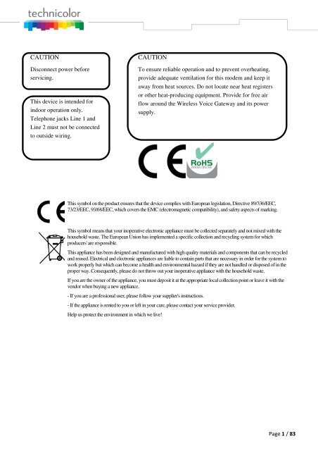
CAUTION<br />
Disconnect power before<br />
servicing.<br />
This device is intended for<br />
indoor operation only.<br />
Telephone jacks Line 1 and<br />
Line 2 must not be connected<br />
to outside wiring.<br />
CAUTION<br />
To ensure reliable operation and to prevent overheating,<br />
provide adequate ventilation for this modem and keep it<br />
away from heat sources. Do not locate near heat registers<br />
or other heat-producing equipment. Provide for free air<br />
flow around the Wireless Voice Gateway and its power<br />
supply.<br />
This symbol on the product ensures that the device complies with European legislation, Directive 89/336/EEC,<br />
73/23/EEC, 93/68/EEC, which covers the EMC (electromagnetic compatibility), and safety aspects of marking.<br />
This symbol means that your inoperative electronic appliance must be collected separately and not mixed with the<br />
household waste. The European Union has implemented a specific collection and recycling system for which<br />
producers' are responsible.<br />
This appliance has been designed and manufactured with high quality materials and components that can be recycled<br />
and reused. Electrical and electronic appliances are liable to contain parts that are necessary in order for the system to<br />
work properly but which can become a health and environmental hazard if they are not handled or disposed of in the<br />
proper way. Consequently, please do not throw out your inoperative appliance with the household waste.<br />
If you are the owner of the appliance, you must deposit it at the appropriate local collection point or leave it with the<br />
vendor when buying a new appliance.<br />
- If you are a professional user, please follow your supplier's instructions.<br />
- If the appliance is rented to you or left in your care, please contact your service provider.<br />
Help us protect the environment in which we live!<br />
Page 1 / 83
NORTH AMERICAN CABLE INSTALLER:<br />
This reminder is provided to call your attention to Article 820-40 of the National Electrical Code (Section<br />
54 of the Canadian Electrical Code, Part 1) which provides guidelines for proper grounding and, in<br />
particular, specifies that the cable ground shall be connected to the grounding system of the building as<br />
close to the point of cable entry as practical.<br />
Operating Information<br />
Operating Temperature: 0˚ - 40˚ C (32˚ - 104˚ F)<br />
Storage Temperature: -20˚ to 70˚ C (-4˚ – 157˚ F)<br />
If you purchased this product at a retail outlet, please read the following:<br />
Product Information<br />
Keep your sales receipt to obtain warranty parts and service and for proof of purchase. Attach it here and<br />
record the serial and model numbers in case you need them. The numbers are located on the back of the<br />
product.<br />
Model No. ____________________________Serial No ________________________________<br />
Purchase Date: ________________________Dealer/Address/Phone: _________________________<br />
Page 2 / 83
Safety Recommendations<br />
REMEMBER SAFETY FIRST<br />
Using equipment safely<br />
Your Cable Modem has been manufactured to meet safety standards, but you must take care if you want it<br />
to perform properly and safely.<br />
It is important that you read this booklet completely, especially the safety instructions below. If you have<br />
any doubts about the installation, operation or safety of decoder, please contact your supplier.<br />
To avoid the risk of electric shock<br />
• Disconnect the Cable Modem from the mains supply before you connect the Cable Modem to (or<br />
disconnect it from) any other equipment. Remember that contact with 110 ~ 240 Volt AC mains can<br />
be lethal or cause severe electric shock.<br />
• Never remove the Cable Modem’s cover. Should the Cable Modem fail, contact the Customer Service<br />
to arrange repair or service.<br />
• Never allow anyone to push anything into holes, slots or any other opening in the case<br />
• Do not block the Cable Modem’s ventilation slots; never stand it on soft furnishings or carpets<br />
• Do not put anything on the Cable Modem which might spill or drip into it (eg. Lighted candles or<br />
containers of liquids). Do not expose the Cable Modem to dripping or splashing. If an object or liquid<br />
enters inside the Cable Modem, unplug it immediately and contact the Customer Service.<br />
• Do not store the Cable Modem in excessively hot, cold or damp conditions. The Cable Modem is<br />
intended to operate at an ambient temperature of less than 40 degrees Celsius and a maximum<br />
humidity level of 75%. In case of a storm, it is recommended that you unplug the Cable Modem from<br />
the mains and from the R/F Network.<br />
• Leave the mains socket accessible so that you can unplug the set quickly<br />
Connecting to the mains supply<br />
• This Cable Modem is designed to operate at 110 ~ 240 VAC.<br />
• If you are in any doubt about the mains lead, the plug or connection, please consult the Customer<br />
Service.<br />
• Only the power adapter supplied with the decoder has to be used<br />
Ensuring optimum performance<br />
• Leave 7cm to 10cm around the Cable Modem to ensure that proper ventilation gets to the Cable<br />
Modem.<br />
• Do not store your Cable Modem on its side (if not allowed)<br />
• To clean the Cable Modem, use a dry, clean soft cloth with no cleaning solvent or abrasive products.<br />
Clean the ventilation openings regularly.<br />
Page 3 / 83
MAIN TECHNICALSPECIFICATIONS<br />
General<br />
Operating voltage<br />
Typical Power consumption<br />
Dimensions (W x H x D)<br />
100 ~ 240 VAC<br />
18 W max<br />
Operating temperature range 0 – 40 °C<br />
Storage temperature range -20 – 70 °C<br />
AC adapter (or plug-in adapter)<br />
type<br />
220mm x 166.7mm x 43mm<br />
ADAPTER 18W 12VDC/1.5A<br />
Connections<br />
DC input 12V/ 1.5A<br />
Cable input<br />
1xCoaxial cable connector<br />
USB input<br />
1x 2.0 USB connector<br />
Phone plugs<br />
2xRJ11<br />
Ethernet plugs<br />
4xRJ-45<br />
This symbol on your set guarantees that your product complies with the European Directives 1999/5/ECand<br />
2009/125/EC on Safety, Telecom, Electromagnetic Compatibility and Energy related Products.<br />
Page 4 / 83
Chapter 1: Connections and Setup .......................................................................................... 8<br />
Turning on the Wireless Voice Gateway ................................................................................ 8<br />
Introduction ........................................................................................................................ 8<br />
Wireless Voice Gateway Features ...................................................................................... 8<br />
What’s on the CD-ROM .................................................................................................... 9<br />
Computer Requirements ................................................................................................... 9<br />
Wireless Voice Gateway Overview......................................................................................... 9<br />
Front Panel ....................................................................................................................... 9<br />
Rear Panel ...................................................................................................................... 12<br />
Wall Mounting ................................................................................................................ 13<br />
Relationship among the Devices ........................................................................................ 14<br />
What the Modem Does ................................................................................................... 14<br />
What the Modem Needs to Do Its Job .............................................................................. 14<br />
Contact Your Local Cable Company ................................................................................ 15<br />
Connecting the Wireless Voice Gateway to a Single Computer ............................................ 15<br />
Attaching the Cable TV Wire to the Wireless Voice Gateway ............................................ 16<br />
Installation procedure for connecting to the Ethernet interface ....................................... 17<br />
Telephone or Fax Connection ......................................................................................... 18<br />
Chapter 2: WEB Configuration ............................................................................................... 19<br />
Accessing the Web Configuration ...................................................................................... 19<br />
Outline of Web Manager ................................................................................................. 21<br />
Status – Status Web Page Group ......................................................................................... 22<br />
1. System ...................................................................................................................... 22<br />
2. Connection/Basic ...................................................................................................... 23<br />
3. Connection/Upstream ............................................................................................... 24<br />
4. Connection/Downstream ........................................................................................... 25<br />
5. MTA/Status ............................................................................................................... 26<br />
6. Diagnostics/Ping ....................................................................................................... 27<br />
7. Diagnostics/Trace Route ........................................................................................... 28<br />
Basic – Basic Web Page Group ............................................................................................ 29<br />
1. Internet ..................................................................................................................... 29<br />
2. Local Area Network ................................................................................................... 30<br />
Page 5 / 83
3. DHCP Client Devices .................................................................................................. 31<br />
Advanced – Advanced Web Page Group .............................................................................. 32<br />
1. Options ..................................................................................................................... 32<br />
2. IP Filters .................................................................................................................... 33<br />
3. MAC Filters................................................................................................................ 34<br />
4. Port Filters ................................................................................................................ 35<br />
5. Forwarding ................................................................................................................ 36<br />
6. Port Triggers ............................................................................................................. 37<br />
7. DMZ Host .................................................................................................................. 38<br />
8. Firewall ..................................................................................................................... 39<br />
Parental Control – Parental Control Web Page Group .......................................................... 40<br />
1. Device Rules .............................................................................................................. 40<br />
2. Basic Setup ................................................................................................................ 42<br />
3. WEB Site Filters .......................................................................................................... 43<br />
4. TOD Filters ................................................................................................................ 45<br />
Wireless – Wireless Web Page Group .................................................................................. 47<br />
1. 2.4 GHz\Radio .......................................................................................................... 48<br />
2. 2.4 GHz\Security ....................................................................................................... 49<br />
3. 2.4 GHz\Advanced .................................................................................................... 50<br />
4. 2.4 GHz\Access Control ............................................................................................ 52<br />
5. 2.4 GHz\WPS ............................................................................................................. 53<br />
6. 5 GHz\Radio ............................................................................................................. 54<br />
7. 5 GHz\Security .......................................................................................................... 55<br />
8. 5 GHz\Advanced ....................................................................................................... 56<br />
9. 5 GHz\Access Control ............................................................................................... 58<br />
10. 5 GHz\WPS .............................................................................................................. 59<br />
USB – USB Web Page Group ................................................................................................ 60<br />
1. USB Basic ................................................................................................................... 60<br />
2. Approuved Devices .................................................................................................... 61<br />
3. Storage Basic ............................................................................................................. 62<br />
4. Storage Advanced ..................................................................................................... 63<br />
Page 6 / 83
5. MEDIA SERVER ........................................................................................................... 64<br />
System – System Web Page Group ...................................................................................... 67<br />
1. Password ................................................................................................................... 67<br />
2. Backup and Recovery\Backup .................................................................................... 68<br />
3. Backup and Recovery\Restore ................................................................................... 69<br />
4. Backup and Recovery\Factory Default ........................................................................ 70<br />
5. Log\Syslog ................................................................................................................ 71<br />
6. Log\Local Log ........................................................................................................... 72<br />
Chapter 3: Networking .......................................................................................................... 73<br />
Communications ............................................................................................................... 73<br />
Type of Communication .................................................................................................... 73<br />
Cable Modem (CM) Section ................................................................................................ 74<br />
Networking Section ........................................................................................................... 74<br />
Three Networking Modes ................................................................................................... 74<br />
Cable Modem (CM) Mode ................................................................................................... 75<br />
Residential Gateway (RG) Mode .......................................................................................... 76<br />
Chapter 4: Additional Information ......................................................................................... 78<br />
Frequently Asked Questions .............................................................................................. 78<br />
General Troubleshooting ................................................................................................... 80<br />
Service Information ........................................................................................................... 81<br />
Glossary ............................................................................................................................ 82<br />
Page 7 / 83
CHAPTER 1: CONNECTIONS AND SETUP<br />
Turning on the Wireless Voice Gateway<br />
After installing the Wireless Voice Gateway and turn it on for the first time (and each time the modem is<br />
reconnected to the power), it goes through several steps before it can be used. Each of these steps is<br />
represented by a different pattern of flashing lights on the front of the modem.<br />
If there is no lighted LEDs on the front panel, check the power adapter plug-in the power jack and<br />
connect to CM correctly.<br />
Note: All indicators flash once before the initialization sequence.<br />
If both DS and US LEDs are flashing, it means the Wireless Voice Gateway is automatically updating its<br />
system software. Please wait for the lights to stop flashing. Do not remove the power supply or reset the<br />
Wireless Voice Gateway during this process.<br />
Introduction<br />
Wireless Voice Gateway Features<br />
Full Band Capture Front End<br />
Lowers Power with Advanced Power Management<br />
Advanced Processor architecture.<br />
Cable Europe Labs Euro-DOCSIS 1.0/1.1/2.0/3.0 Standard certified.<br />
Euro-PacketCable 1.0/1.5 Standard certified.<br />
Support Multiple Provisioning mode.<br />
Standard RJ-45 connector for 10/100/1000BaseT Ethernet with auto-negotiation and MDIX functions.<br />
RJ-11 Foreign Exchange Station (FXS) port for IP telephony.<br />
Support simultaneous voice and data communications.<br />
Echo Cancellation.<br />
Voice Active Detection (VAD).<br />
DTMF detection and generation.<br />
Comfort Noise Generation (CNG).<br />
Support V.90 fax and modem services.<br />
SNMP network management support.<br />
802.11a/b/g/n are supported, 20/40 MHz bandwidth.<br />
Support Web pages and private DHCP server for status monitoring.<br />
Page 8 / 83
What’s on the CD-ROM<br />
Insert the Wireless Voice Gateway CD-ROM into your CD-ROM drive to view troubleshooting tips, the<br />
internal diagnostics, and other valuable information.<br />
CD-ROM Contents:<br />
• Electronic copy of this user’s guide in additional languages (PDF format)<br />
• Adobe Acrobat Reader — application you can load to read PDF format, if you don’t have it<br />
loaded already<br />
• Links to <strong>Technicolor</strong> web site<br />
Euro-DOCSIS and Euro-PacketCable are trademarks of Cable Television Laboratories, Inc.<br />
Computer Requirements<br />
For the best possible performance from your Wireless Voice Gateway, your personal computer must meet<br />
the following minimum system requirements (note that the minimum requirements may vary by cable<br />
companies):<br />
IBM PC COMPATIBLE<br />
MACINTOSH**<br />
CPU Pentium preferred PowerPC or higher<br />
System RAM 16MB (32MB preferred) 24MB (32MB preferred)<br />
Operating System Windows* NT / 2000 / Me / XP /<br />
Vista / Windows 7, Linux<br />
Mac OS** 7.6.1 or higher<br />
Video VGA or better (SVGA preferred) VGA or better (SVGA built-in preferred)<br />
CD-ROM Drive Required Required<br />
Ethernet<br />
10BaseT , 100BaseT or 1000BaseT 10BaseT , 100BaseT or 1000BaseT<br />
An Ethernet card makes it possible for your computer to pass data to and from<br />
the internet. You must have an Ethernet card and software drivers installed in<br />
your computer. You will also need a standard Ethernet cable to connect the<br />
Ethernet card to your Wireless Voice Gateway.<br />
Software • A TCP/IP network protocol for each machine<br />
* Windows is a trademark of Microsoft Corporation.<br />
** Macintosh and the Mac OS are trademarks of Apple Computer, Inc.<br />
• Microsoft Internet Explorer 4.0 or later or<br />
Netscape Navigator 4.0 or later.<br />
Wireless Voice Gateway Overview<br />
Front Panel<br />
Page 9 / 83
Fig. 1-1 Front Panel<br />
The following illustration shows the front panel:<br />
Power - Indicates the Power status.<br />
DS - Indicates the status of Data reception by the cable modem from the Network<br />
(Downstream Traffic).<br />
US - Indicates the status of Data transmission by the cable modem to the Network<br />
(Upstream Traffic).<br />
Online - Displays the status of your cable connection. The light is off when no<br />
cable connection is detected and fully lit when the modem has established a<br />
connection with the network and data can be transferred.<br />
Eth. - Indicates the state of Ethernet ports.<br />
Wireless - Indicates the traffic on the wireless network.<br />
Tel - Indicates the status of the telephone Phone 1 and Phone 2.<br />
Page 10 / 83
The lights on the front panel LEDs are described in the table below (from left to right):<br />
ON = the LED is light, OFF = the LED is gray, FLASH = the LED is blinking.<br />
TC7200.U<br />
Boot-up<br />
Operation<br />
DOCSIS<br />
Start-up<br />
Operation<br />
Channel<br />
Bonding<br />
Operation<br />
MTA<br />
initialization<br />
CPE<br />
Operation<br />
MTA<br />
Operation<br />
Power<br />
Internet<br />
DS US Online<br />
ON ON ON ON<br />
ON<br />
0.25 second<br />
Eth. Wireless Phone 1 Phone 2 Description<br />
ON X ON ON Power on 0.25 sec<br />
ON FLASH FLASH FLASH X X X X<br />
ON<br />
ON ON ON<br />
1 second<br />
X X X X<br />
From power ON to system initialization<br />
complete<br />
Following system initialization<br />
complete to (before) DS scanning<br />
ON FLASH OFF OFF X X X X During DS scanning and acquiring SYNC<br />
ON ON FLASH OFF X X X X<br />
ON ON ON FLASH X X X X<br />
From SYNC completed, receiving UCD<br />
to ranging completed<br />
During DHCP, configuration file<br />
download, registration, and Baseline<br />
Privacy initialization:<br />
DHCP status: 1 second ON and 1<br />
second OFF,<br />
TFTP status: 0.25 second ON and 0.25<br />
second OFF<br />
ON ON ON ON X X X X Operational (NACO=ON)<br />
ON FLASH FLASH OFF X X X X Operational (NACO=OFF)<br />
FLASH FLASH FLASH FLASH FLASH X X X<br />
X X X X OFF X X X<br />
OFF X X X X X X X<br />
FLASH FLASH FLASH FLASH FLASH X X X<br />
Wait registration with all DS and all<br />
US – Lights Flash sequentially from the<br />
right to left Minimum duration 3<br />
seconds<br />
From 1 to 4 DS, from 1 to 4 LEDs are<br />
ON<br />
From 5 to 8 DS, From 1 to 4 LEDs are<br />
flashing<br />
Duration 3 seconds<br />
ON ON ON ON X X FLASH OFF MTA DHCP<br />
ON ON ON ON X X OFF FLASH MTA SNMP/TFTP<br />
From 1 to 4 US, from 1 to 4 LEDs are<br />
ON.<br />
Wait registration with all DS and all<br />
US – Lights Flash sequentially from the<br />
left to right<br />
ON ON ON ON X X ON ON RSIP for NCS/Register for SIP<br />
ON X X X<br />
ON<br />
OFF<br />
ON<br />
FLASH<br />
OFF<br />
ON<br />
FLASH<br />
X<br />
X<br />
No Ethernet / Wireless Link<br />
Ethernet / Wireless Link<br />
TX/RX Ethernet / Wireless Traffic<br />
ON ON Both Lines On-Hook<br />
ON FLASH ON Tel1 Off-hook, Tel2 On-hook<br />
<br />
ON ON FLASH Tel1 On-hook, Tel2 Off-hook<br />
ON FLASH FLASH Both Lines Off-Hook<br />
Page 11 / 83
SW<br />
Download<br />
Operation<br />
ON FLASH FLASH ON X X X X<br />
A software download and while<br />
updating the FLASH memory<br />
Table 1-1 LED behavior<br />
Rear Panel<br />
Fig. 1-2 Rear Panel<br />
Connector<br />
Power Switch<br />
Power Jack<br />
Cable<br />
Reset<br />
USB Host<br />
Etherent<br />
Phone1/ Phone2<br />
Description<br />
Power on, off the Cable modem.<br />
Connector for DC12V.<br />
Connector for the cable network.<br />
To restart the modem or press over 5 seconds can<br />
default the modem.<br />
USB 2.0 connector<br />
4 Gige Ethernet ports, RJ-45 connector.<br />
2 Phone RJ11 Connectors.<br />
Table 1-2 Rear Panel description<br />
Side Panel for WPS<br />
Fig. 1-3 Side Panel<br />
WPS – Indicates the status of the WPS functionality.<br />
WPS button: Wi-Fi Protected Setup TM . This button can be used to:<br />
Secure the connection with another device (PC for example) using WPS protocol. A long press (press<br />
2 more seconds) on the button allows you to enable the association of the modem with a PC or other<br />
equipment.<br />
After link establish. A short press on the button, switch on/off Wi-Fi.<br />
Page 12 / 83
Wall Mounting<br />
This article will show the user through the process of wall-mounting the Wireless Voice Gateway<br />
The Adapter has two wall-mount slots on its back panel.<br />
Two screws are needed to mount the Adapter.<br />
To do this:<br />
Fig. 1-4 Wall Mounting<br />
1. Ensure that the wall you use is smooth, flat, dry and sturdy and use the 2 screw holes<br />
which are 101.6 mm (4 inches) apart from each other.<br />
2. Fix the screws into wall, leaving their heads 3 mm (0.12 inch) clear of the wall surface.<br />
3. Remove any connections to the unit and locate it over the screw heads. When in line,<br />
gently push the unit on to the wall and move it downwards to secure.<br />
Page 13 / 83
Relationship among the Devices<br />
This illustration shows a cable company that offers DOCSIS/Euro-DOCSIS and PacketCable/Euro-<br />
PacketCable compliant voice/data services.<br />
What the Modem Does<br />
Fig. 1-5 Connection overview<br />
The Wireless Voice Gateway provides high-speed Internet access as well as cost-effective, toll-quality<br />
telephone voice and fax/modem services over residential, commercial, and education subscribers on<br />
public and private networks via an existing CATV infrastructure. It can inter-operate with the<br />
PacketCable compliant head-end equipment and provide the IP-based voice communications. The IP<br />
traffic can transfer between the Wireless Voice Gateway and DOCSIS/Euro-DOCSIS compliant head-end<br />
equipment. The data security secures upstream and downstream communications.<br />
What the Modem Needs to Do Its Job<br />
The Right Cable Company: Make sure your local cable company provides data services that use<br />
cable TV industry-standard DOCSIS/Euro-DOCSIS compliant and PacketCable/Euro-<br />
PacketCable compliant technology.<br />
The Internet/Telephony Service Provider (ISP/TSP): Your cable company provides you access<br />
to an Internet Service Provider (ISP) and Telephony Service Provider (TSP). The ISP is your<br />
gateway to the Internet and provides you with a pipeline to access Internet content on the World<br />
Wide Web (WWW). The TSP provides you with telephony access to other modems or other<br />
telephony services over the Public Switched Telephone Network (PSTN).<br />
Check with your cable company to make sure you have everything you need to begin; they’ll know if you<br />
need to install special software or re-configure your computer to make your cable internet service work<br />
for you.<br />
Page 14 / 83
Contact Your Local Cable Company<br />
You will need to contact your cable company to establish an Internet account before you can use your<br />
gateway. You should have the following information ready (which you will find on the sticker on the<br />
gateway):<br />
• The serial number<br />
• The model number<br />
• The Cable Modem (CM) Media Access Control (MAC) address<br />
• The Terminal Adapter (EMTA) MAC address<br />
• Security information: Service Set Identifier (SSID), Encryption key / passphrase (WPA2-PSK by<br />
default), channel number. Default values are indicated underneath the modem on the sticker.<br />
Please check the following with the cable company<br />
The cable service to your home supports DOCSIS/Euro-DOCSIS compliant two-way modem<br />
access.<br />
Your internet account has been set up. (The Media Terminal Adapter will provide data service if<br />
the cable account is set up but no telephony service is available.)<br />
You have a cable outlet near your PC and it is ready for Cable Modem service.<br />
Note: It is important to supply power to the modem at all times. Keeping your modem plugged in will<br />
keep it connected to the Internet. This means that it will always be ready whenever you need.<br />
Important Information<br />
Your cable company should always be consulted before installing a new cable outlet. Do not attempt any<br />
rewiring without contacting your cable company first.<br />
Please verify the following on the Wireless Voice Gateway<br />
The Power LED should be lighted when plug-in the power supply.<br />
Connecting the Wireless Voice Gateway to a Single Computer<br />
This section of the manual explains how to connect your Wireless Voice Gateway to the Ethernet port on<br />
your computer and install the necessary software. Please refer to Figure 1-5 to help you connect your<br />
Digital Cable Modem for the best possible connection.<br />
Page 15 / 83
Attaching the Cable TV Wire to the Wireless Voice Gateway<br />
1. Locate the Cable TV wire. You may find it one of three ways:<br />
a. Connected directly to a TV, a Cable TV converter box, or VCR. The line will be connected to<br />
the jack, which should be labeled either IN, CABLE IN, CATV, CATV IN, etc.<br />
b. Connected to a wall-mounted cable outlet.<br />
c. Coming out from under a baseboard heater or other location. See Figure 1-6 for the wiring<br />
example.<br />
Notes: For optimum performance, be sure to connect your<br />
Wireless Voice Gateway to the first point the cable enters<br />
your home. The splitter must be rated for at least 1GHz.<br />
Fig. 1-6 Basic Home Wiring<br />
Page 16 / 83
Installation procedure for connecting to the Ethernet interface<br />
Follow these steps for proper installation.<br />
Plug the coaxial cable to the cable wall outlet and the other end to the modem’s cable connector.<br />
Note: To ensure a fast registration of the modem, the coaxial cable must be connected to<br />
the modem before it is powered on.<br />
Plug the power supply into the socket of the cable modem and two-pin plug in the AC outlet then press<br />
the Power Switch, power on the modem.<br />
Note: Only use the power supply that comes with the modem. Using another power supply<br />
can cause damage to the product, and will void the warranty.<br />
Connect an Ethernet cable (direct connection, see below) to the Ethernet port at the back of the computer,<br />
and the other end to the ETHERNET port on the rear panel of the cable modem. The modem will seek the<br />
appropriate cable signal on the cable television network and go through the initial registration process on<br />
its own. The modem is ready for data transfer after the green LED "ONLINE" is lit continuously.<br />
Note: the button "reset" at the back of the modem is used primarily for maintenance.<br />
Fig. 1-7 Connect to the Modem<br />
Page 17 / 83
Telephone or Fax Connection<br />
When properly connected, most telephony devices can be used with the Wireless Voice Gateway just as<br />
with a conventional telephone service. To make a normal telephone call, pick up the handset; listen for a<br />
dial tone, then dial the desired number. For services such as call waiting, use the hook switch (or FLASH<br />
button) to change calls. The following procedures describe some of the possible connection schemes for<br />
using telephony devices with the Wireless Voice Gateway.<br />
1. Connect a standard phone line cord directly from the phone (fax machine, answering machine, caller<br />
ID box, etc.) to one of the LINE jacks on the Wireless Voice Gateway.<br />
2. If there is a phone line in your home which is NOT connected to another telephone service provider,<br />
connect a standard phone line cord from a jack on this line to one of the LINE jacks of the Wireless<br />
Voice Gateway. Connect a standard phone line cord directly from the phone (fax machine, answering<br />
machine, caller ID box, etc.) to one of the other jacks in the house that uses that line.<br />
3. If you have a multi-line telephone, connect a standard phone line cord (not an RJ-14 type line cord)<br />
from the phone to the LINE jacks on the Wireless Voice Gateway. (Other phones can be added to<br />
each line by using standard phone line splitters.)<br />
Page 18 / 83
CHAPTER 2: WEB CONFIGURATION<br />
To make sure that you can access the Internet successfully, please check the following first.<br />
1. Make sure the connection (through Ethernet) between the Wireless Voice Gateway and your<br />
computer is OK.<br />
2. Make sure the TCP/IP protocol is set properly.<br />
3. Subscribe to a Cable Company.<br />
Accessing the Web Configuration<br />
The Wireless Voice Gateway offers local management capability through a built-in HTTP server and a<br />
number of diagnostic and configuration web pages. You can configure the settings on the web page and<br />
save them to the device.<br />
Once your host PC is properly configured; please proceed as follows:<br />
1. Start your web browser and type the private IP address of the Wireless Voice Gateway on<br />
the URL field: 192.168.0.1<br />
2. After connecting to the device, you will be prompted to select a Country and Language.<br />
This page will be brought to you at the first login if the device has been set to user or<br />
operator factory defaults. Select the country and language that you preferred and then click<br />
“Next” for proceeding to Login page.<br />
Fig2-1 Country and Language page<br />
Page 19 / 83
3. You will be prompted to enter username and password if this is not the first login. By<br />
default, the username is “admin” and the password is “admin”.<br />
Fig2-2 Login page<br />
If you login successfully, the main page will appear.<br />
The following page will be displayed if the given username or password is wrong.<br />
Fig2-3 Wrong username/password page<br />
Page 20 / 83
Outline of Web Manager<br />
The main screen will be shown as below.<br />
<br />
<br />
<br />
<br />
<br />
Fig. 2-4 Outline of Web Manager<br />
Main Menu: the hyperlinks on the top of the page, including STATUS, BASIC, ADVANCED,<br />
PARENTAL CONTROL, WIRELESS and SYSTEM items<br />
Sub Menu: the sidebar on the left side of the page indicates the title of this management interface,<br />
e.g., Status in this example<br />
Main Window: the current workspace of the web management, containing configuration or status<br />
information<br />
Language List: List all of the language supported. Click the drop list and select the language that<br />
you preferred.<br />
Logout: Click “Logout” for logging out.<br />
For easy navigation, the pages are organized in groups with group in names main menu. Individual page<br />
names within each group are provided in the sub menu and sidebar. So to navigate to a page, click the<br />
group hyperlink at the top, then the sub menu for the function, finally choose the title on the sidebar.<br />
Your cable company may not support the reporting of some items of information listed on your gateway’s<br />
internal web pages. In such cases, the information field appears blank. This is normal.<br />
Page 21 / 83
Status – Status Web Page Group<br />
1. System<br />
This page displays system information about your cable modem.<br />
The CM Software information section of this page shows how long your gateway has operated since last<br />
time being powered up, and some key information the Cable Modem received during the initialization<br />
process with your cable company. If Network Access shows “Allowed,” then your cable company has<br />
configured your gateway to have Internet connectivity. If not, you may not have Internet access, and<br />
should contact your cable company to resolve this.<br />
Fig.2-5 Status\System<br />
Page 22 / 83
2. Connection/Basic<br />
This page reports current CM basic connection information containing Connectivity State, Boot State,<br />
Security, CM IP address, Lease Time, Lease Expiration and current System time. The information can be<br />
useful to your cable company’s support technician if you’re having problems.<br />
Fig. 2-6 Status\Connection\Basic<br />
Page 23 / 83
3. Connection/Upstream<br />
This page reports current CM’s upstream information containing Transmitter #, Channel ID, Lock Status,<br />
Frequency, Modulation, Symbol Rate, Channel Type and Power. The information can be useful to your<br />
cable company’s support technician if you’re having problems.<br />
Fig. 2-7 Status\Connection\Upstream<br />
Page 24 / 83
4. Connection/Downstream<br />
This page reports current CM’s downstream information containing Receiver #, Channel ID, Lock Status,<br />
Frequency, Modulation, Symbol Rate, SNR and Power. The information can be useful to your cable<br />
company’s support technician if you’re having problems. By entering frequency in KHz and clicking<br />
“Force frequency” button, you can force the CM locking to the specified frequency.<br />
Fig. 2-8 Status\Connection\Downstream<br />
Page 25 / 83
5. MTA/Status<br />
This page displays the initialization status of the MTA containing Telephony DHCP, Security, TFTP, Call<br />
Server and Provisioning Status. The information can be useful to your cable company’s support<br />
technician if you’re having problems.<br />
The MAC List state can be found at the bottom of this page. It reports the current state of Line1 and<br />
Line2.<br />
Fig. 2-9 Status\MTA\Status<br />
Page 26 / 83
6. Diagnostics/Ping<br />
This page can be used for determining the quality of your network connection. By setting up the<br />
Destination IP address, Packet size, Packet count and then clicking “Start” button, you can check and<br />
determine the quality of network connection. The result of Ping will be displayed at the frame under<br />
Packet count. You can click the “Abort” button at any time during Ping test to abort the test. The<br />
information can be useful to your cable company’s support technician if you’re having problems.<br />
Fig. 2-10 Status\Diagnostics\Ping<br />
Page 27 / 83
7. Diagnostics/Trace Route<br />
With this page you can perform trace route to display the route (path) and measure transit delays of<br />
packets. In order to do trace route, a host IP and maximum TTL must be entered prior to start. Host IP is<br />
the destination that you plan to trace route to. The value of MAX TTL ranges from 1 to 30 seconds.<br />
Result of trace route will be displayed in ping text frame. You can click the “Abort” button at any time<br />
during trace route test to abort the test. The information can be useful to your cable company’s support<br />
technician if you’re having problems.<br />
Fig. 2-11 Status\Diagnostics\Trace Route<br />
Page 28 / 83
Basic – Basic Web Page Group<br />
1. Internet<br />
This page shows you the basic configuration of broadband gateway related to your MSO’s connection. It<br />
allows configuration of Host Name and Domain Name if needed.<br />
Clicking “WAN IP Renew” button will force the modem renewing WAN IP immediately.<br />
Fig.2-12 Basic\Internet<br />
Page 29 / 83
2. Local Area Network<br />
This page allows you to configure Local Area Network, DHCP server, DNS server and Domain Name.<br />
Fig. 2-13 Basic\Local Area Network<br />
Page 30 / 83
3. DHCP Client Devices<br />
This page reports current DHCP client information containing Mac Address, IP Address and Time<br />
expiration of each client if the DHCP server was enabled in Local Area Network page.<br />
Fig. 2-14 Basic\DHCP Client Devices<br />
Page 31 / 83
Advanced – Advanced Web Page Group<br />
1. Options<br />
This page allows you to configure router options. You can activate settings by checking them and clicking<br />
“Save” button.<br />
Fig.2-15 Advanced\Options<br />
<br />
<br />
<br />
<br />
<br />
WAN Blocking prevents others on the WAN side from being able to ping your gateway. With WAN<br />
Blocking enabled, your gateway will not respond to pings it receives, effectively “hiding” your<br />
gateway.<br />
IPSec Pass Through enables IPSec type packets to pass WAN LAN. IPSec (IP Security) is a<br />
security mechanism used in Virtual Private Networks (VPNs).<br />
PPTP Pass Through enables PPTP type packets to pass WAN LAN. PPTP (Point to Point<br />
Tunneling Protocol) is another mechanism sometimes used in VPNs.<br />
Multicast enables multicast traffic to pass WAN LAN. You may need to enable this to see some<br />
types of broadcast streaming and content on the Internet.<br />
UPnP Universal Plug and Play (UPnP) helps devices, such as Internet appliances and computers,<br />
access the network and connect to other devices as needed. UPnP devices can automatically discover<br />
the services from other registered UPnP devices on the network.<br />
Page 32 / 83
2. IP Filters<br />
This page enables you to enter the IP address ranges of PCs on your LAN that you don’t want to have<br />
outbound access to the WAN. These PCs can still communicate with each other on your LAN, but<br />
packets they send to WAN addresses are blocked by the gateway.<br />
Fig. 2-16 Advanced\IP Filters<br />
You can add a blank row to the list by clicking “Add row” button. Entering the IP address range of PCs<br />
on your LAN and then clicking “Save” button for saving the configuration.<br />
Check the “Delete” option of a row and then clicking “Save” button for deleting the row.<br />
Page 33 / 83
3. MAC Filters<br />
This page enables you to enter the MAC address of specific PCs on your LAN that you do not wish to<br />
have outbound access to the WAN. As with IP filtering, these PCs can still communicate with each other<br />
through the gateway, but packets they send to WAN addresses are blocked.<br />
Fig. 2-17 Advanced\MAC Filters<br />
You can add a blank row to the list by clicking “Add row” button. Entering the MAC address of PC on<br />
your LAN and then clicking “Save” button for saving the configuration.<br />
Check the “Delete” option of a row and then clicking “Save” button for deleting the row.<br />
Page 34 / 83
4. Port Filters<br />
This page allows you to enter ranges of destination ports (applications) that you don’t want your LAN<br />
PCs to send packets to. Any packets your LAN PCs send to these destination ports will be blocked. For<br />
example, you could block access to worldwide web browsing (http = port 80) but still allow email service<br />
(SMTP port 25 and POP-3 port 110). To enable port filtering, set Start Port and End Port for each range,<br />
and click Apply. To block only one port, set both Start and End ports with the same value.<br />
Fig.2-18 Advanced\Port Filters<br />
You can add a blank row to the list by clicking “Add row” button. Entering the port range and protocol<br />
that you want to block and then clicking “Save” button for saving the configuration.<br />
Check the “Delete” option of a row and then clicking “Save” button for deleting the row.<br />
The protocol option can be Both, UDP or TCP. Both of UDP and TCP port will be blocked if “Both” was<br />
selected.<br />
Page 35 / 83
5. Forwarding<br />
For LAN WAN communications, the gateway normally only allows you to originate an IP connection<br />
with a PC on the WAN; it will ignore attempts of the WAN PC to originate a connection onto your PC.<br />
This protects you from malicious attacks from outsiders. However, sometimes you may wish for anyone<br />
outside to be able to originate a connection to a particular PC on your LAN if the destination port<br />
(application) matches one you specify.<br />
Fig. 2-19 Advanced\Forwarding<br />
You can add a blank row to the list by clicking “Add row” button. Entering the public port range, target<br />
IP address, target port range and protocol that you want to forward and then clicking “Save” button for<br />
saving the configuration.<br />
Check the “Delete” option of a row and then clicking “Save” button for deleting the row.<br />
The protocol option can be Both, UDP or TCP. Both of UDP and TCP port will be blocked if “Both” was<br />
selected.<br />
Page 36 / 83
6. Port Triggers<br />
Some Internet activities, such as interactive gaming, require that a PC on the WAN side of your gateway<br />
be able to originate connections during the game with your game playing PC on the LAN side. You could<br />
use the Advanced-Forwarding web page to construct a forwarding rule during the game, and then remove<br />
it afterwards (to restore full protection to your LAN PC) to facilitate this. Port triggering is an elegant<br />
mechanism that does this work for you, each time you play the game.<br />
Fig. 2-20 Advanced\Port Triggers<br />
Port Triggering works as follows. Imagine you want to play a particular game with PCs somewhere on<br />
the Internet. You make one time effort to set up a Port Trigger for that game, by entering into Trigger<br />
Start Port and Tigger End Port the range of destination ports your game will be sending to, and<br />
entering into Target Start Port the range of destination ports the other player (on the WAN side) will be<br />
sending to (ports your PC’s game receives on). Application programs like games publish this information<br />
in user manuals. Later, each time you play the game, the gateway automatically creates the forwarding<br />
rule necessary. This rule is valid until 10 minutes after it sees game activity stop. After 10 minutes, the<br />
rule becomes inactive until the next matched outgoing traffic arrives.<br />
e.g., suppose you specify Trigger Range from 6660 to 6670 and Target Range from 113 to 113. An<br />
outbound packet arrives at the gateway with your game-playing PC source IP address 192.168.0.10,<br />
destination port 666 over TCP/IP. This destination port is within the Trigger destined for port 113 to your<br />
game-playing PC at 192.168.0.10.<br />
Page 37 / 83
7. DMZ Host<br />
Use this page to designate one PC on your LAN that should be left accessible to all PCs from the WAN<br />
side, for all ports. e.g., if you put an HTTP server on this machine, anyone will be able to access that<br />
HTTP server by using your gateway IP address as the destination. A setting of “0” indicates NO DMZ PC.<br />
“Host” is another Internet term for a PC connected to the Internet.<br />
Fig.2-21 Advanced\DMZ Host<br />
Page 38 / 83
8. Firewall<br />
These pages allow you to enable, disable, and configure a variety of firewall features associated with web<br />
browsing, which uses the HTTP protocol and transports HTML web pages. On these pages, you designate<br />
the gateway packet types you want to have forwarded or blocked. You can activate settings by checking<br />
them and clicking “Save” button.<br />
The web-related filtering features you can activate from the Firewall page include Filter Cookies, Filter<br />
Java Applets, Filter ActiveX, Filter Popup Windows, Block Fragmented IP Packets, Port Scan Detection,<br />
IP Flood Detection, and Firewall Protection.<br />
Fig. 2-22 Advanced\Firewall<br />
Page 39 / 83
Parental Control – Parental Control Web Page Group<br />
1. Device Rules<br />
This page allows you to add and delete Web Site and ToD filter for specified Device. You can save the<br />
settings by clicking “Save” button.<br />
Fig.2-23 Parental Control\Device Rules<br />
A new device can be added to the list by clicking “Add a Device” button. The “Add a Device” dialogue<br />
will be displayed. Please enter Device Name and MAC address for the device that you want adding to the<br />
list and then clicking “Add Device” button.<br />
Fig.2-24 Parental Control\Add Device<br />
Page 40 / 83
Web Site Filters: The filter can be defined in WEB Site Filters page. Select the filter from the drop<br />
down list and click “Save” button for saving it.<br />
ToD Filters: The filter can be defined in ToD Filters page. Select the filter from the drop down list<br />
and click “Save” button for saving it.<br />
Trusted: Check the Trusted checkbutton and click “Save” button for making the device be trusted.<br />
Delete: Check the delete checkbutton and click “Save” button for deleting the device.<br />
Page 41 / 83
2. Basic Setup<br />
This page allows you to enable Parental Control and bypass all blocks in Parental Control.<br />
Fig. 2-25 Parental Control\Basic Setup<br />
<br />
<br />
<br />
<br />
<br />
<br />
<br />
Enable Parental Control: By clicking drop list of Enable Parental Control, select Enabled, enter<br />
password and then clicking “Save” button for enabling Parental Control.<br />
Password: Enter a password for configuring Parental Control. The same password MUST be enter<br />
in field Retype Password.<br />
Retype Password: Enter same password as the one in Password field.<br />
Access Duration: It is the available time of the Override Password.<br />
Override Password: It is used to bypass all blocks in Parental Control.<br />
Mac Address : Enter the MAC address of computers that you trusted and then clicking the “Add to<br />
trusted computers” for adding it.<br />
Remove selected : Select computer that you want to remove from the Trusted Computers list and<br />
then clicking the “Remove selected” button for removing it.<br />
Page 42 / 83
3. WEB Site Filters<br />
This page allows you to configure the web sites that can be reached, should be blocked, or should be<br />
blocked if specific keywords were found. You can add the configuration to a new policy or remove a<br />
policy from the list.<br />
Fig. 2-26 Parental Control\WEB Site Filters<br />
<br />
Policies: A list of available WEB site filter policy. Select a policy from the drop list and then click<br />
“Submit” button for making it the current policy. Select a policy from the drop list and then click<br />
“Remove current policy” for removing it. A new policy can be added by clicking “Add new policy”<br />
button. Entering policy name to “Add a Policy” dialogue page and clicking “Create” button for<br />
adding it to the list<br />
Page 43 / 83
Fig. 2-27 Parental Control\Add a Policy<br />
<br />
<br />
<br />
Keywords: WEB pages contain the keywords list in the filed will be blocked.<br />
Blocked domains: Domains list in this filed will be blocked.<br />
Allowed domains: Domains list in this filed will be allowed for accessing.<br />
Page 44 / 83
4. TOD Filters<br />
Use this page to set rules that will block LAN side PCs from accessing the Internet, but only at specific<br />
days and times. By clicking time block for selecting/deselecting a specific hour. Finally, click the<br />
“Submit” button to save your settings.<br />
Fig.2-28 Parental Control\TOD Filters<br />
<br />
Policies: A list of available TOD filter policy. Select a policy from the drop list and then click<br />
“Submit” button for making it the current policy. Select a policy from the drop list and then click<br />
“Remove” for removing it. A new policy can be added by clicking “Add” button. Entering policy<br />
name to “Add a Policy” dialogue page and clicking “Create” button for adding it to the list<br />
Page 45 / 83
Fig. 2-29 Parental Control\Add a Policy<br />
<br />
<br />
<br />
To click on each hour block and making it in blue color will cause the modem to block Internet<br />
traffic at that hour. To click on the blue block again to make it accessable.<br />
Clear: Click “Clear” button for clearing all of block hour.<br />
Inverse: Click “Inverse” button for reverse the status of all the hour blocks.<br />
Page 46 / 83
Wireless – Wireless Web Page Group<br />
The Wireless web pages group enables a variety of settings that can provide secure and reliable wireless<br />
communications for even the most demanding tech-savvy user.<br />
The Wireless Voice Gateway offers a choice of 802.11b/g/n, WPA and WPA-PSK authentication of your<br />
PCs to the gateway, 64 and 128 bit WEP encryption of communication between the gateway and your<br />
PCs to guaranty security, and an Access Control List function that enables you to restrict wireless access<br />
to only your specific PCs.<br />
Performance<br />
Because your wireless communication travels through the air, the factory default wireless channel setting<br />
may not provide optimum performance in your home if you or your neighbors have other interfering<br />
2.4GHz or 5 GHz devices such as cordless phones. If your wireless PC is experiencing very sluggish or<br />
dramatically slower communication compared with the speed you achieve on your PC that is wired to the<br />
gateway, try changing the channel number. See the 802.11b/g/n Basic Web Page discussion below for<br />
details.<br />
Authentication<br />
Authentication enables you to restrict your gateway from communicating with any remote wireless PCs<br />
that aren’t yours. The following minimum authentication-related changes to factory defaults are<br />
recommended. See the 802.11b/g/n Basic and Access Control Web Page discussions below for details.<br />
Network Name (SSID) – Set a unique name you choose<br />
Network Type – Set to Open<br />
Access Control List – Enter your wireless PCs’ MAC addresses<br />
Security<br />
Security secures or scrambles messages traveling through the air between your wireless PCs and the<br />
gateway, so they can’t be observed by others. The following minimum security setting changes to factory<br />
defaults are recommended. See the 802.11b/g/n Security Web Page discussion below for details.<br />
Page 47 / 83
1. 2.4 GHz\Radio<br />
This page allows you to configure the access control of 2.4GHz AP.<br />
Fig.2-30 Wireless\2.4GHz\Radio<br />
<br />
<br />
<br />
Enable: It may help you to Enable or Disable the 2.4 GHz wireless function. To enable you need to<br />
select Enabled, to disable you need to select Disabled.<br />
SSID: The SSID for 2.4 GHz wireless function.<br />
802.11 Mode: There are three different modes can be selected. Mixed, Disabled and Greenfield.<br />
Channel: In 802.11 Band 2.4GHz, there are 1 to 13 channels. In 802.11 Band 5GHz, there are 36,<br />
40, 44, 48 total 4 channels for all country. Choose the one that is suitable for this device.<br />
<br />
<br />
Bandwidth: Select wireless channel width 20 MHz is for default value (bandwidth taken by<br />
wireless signals of this access point.) It can be 20 MHz or 40 MHz.<br />
Power: This setting decides the output power of this 2.4 GHz device. You may use it to economize<br />
on electricity by selecting lower percentage of power output. Control the range of the AP by<br />
adjusting the radio output power. The power can be 100%, 75%, 50% or 25%.<br />
Page 48 / 83
2. 2.4 GHz\Security<br />
This page allows you to configure security of wireless.<br />
Fig. 2-31 Wireless\2.4GHz\Security<br />
<br />
<br />
Wireless security mode: The wireless security mode can be either WPA Personal or WPA.<br />
Authentication: The method of authentication can be WPA/WPA2 or WPA.<br />
Passphrase: You can enter ASCII codes into this field. The range is from 8 characters to 64<br />
characters. For ASCII characters, you can key in 63 characters in this field. If you want to key in<br />
64 characters, only hexadecimal characters can be used.<br />
<br />
Retype Passphrase: Enter the passphrase again for confirmation.<br />
Page 49 / 83
3. 2.4 GHz\Advanced<br />
This page allows configuring advance wireless settings.<br />
Fig. 2-32 Wireless\2.4GHz\Advanced<br />
<br />
<br />
<br />
<br />
<br />
<br />
Country: Please select the country code.<br />
Mac Address: The MAC address for this wireless device will be displayed in this field<br />
automatically.<br />
Beacon Interval: Set the period of beacon transmissions to allow mobile stations to locate and<br />
identify a BSS. The measure unit is “time units” (TU) of 1024 microseconds. (Value range: 1~65535)<br />
DTIM Interval: The value you set here is used to inform mobile stations when multicast frames that<br />
have been buffered at the Wireless Voice Gateway will be delivered and how often that delivery<br />
occurs. (Value range: 1~255)<br />
Fragment Threshold: Set the number of the fragmenting frames to make the data to be delivered<br />
without errors induced by the interference. Frames longer than the value you set here are fragmented<br />
before the initial transmission into fragments no longer than the value of the threshold. (Value range:<br />
256~ 2346)<br />
RTS Threshold: Set the value for sending a request to the destination. All the frames of a length<br />
Page 50 / 83
greater than the threshold that you set here will be sent with the four-way frame exchange. And, a<br />
length less than or equal to the value that you set will not be proceeded by RTS. (Value range: 0~<br />
2347)<br />
WMM: Wi-Fi Multimedia (WMM) is a component of the IEEE 802.11e wireless LAN standard for<br />
quality of service (QoS). The QoS assigns priority to the selected network traffic and prevents packet<br />
collisions and delays thus improving VoIP calls and watching video over WLANs. It may help you<br />
to Enable or Disable the WMM function. To enable you need to select Enabled, to disable you need<br />
to select Disabled.<br />
WMM Power Save: This field allows you to enable WMM Power Save-Support. To enable you<br />
need to select Enabled, to disable you need to select Disabled.<br />
Page 51 / 83
4. 2.4 GHz\Access Control<br />
This page allows configuring access control.<br />
Fig.2-33 Wireless\2.4GHz\Access Control<br />
<br />
<br />
<br />
<br />
Policies: Policy of access control settings. Two options can be selected. It can be either Allow List<br />
or Deny List.<br />
Mac Address: The MAC address list that allow of deny access.<br />
Add row: Click ”Add row” for adding a new row of Mac Address.<br />
Delete: Check ”Delete” of a raw and click”Save” button for deleting it.<br />
Page 52 / 83
5. 2.4 GHz\WPS<br />
This page allows you to configure WPS setting. Wi-Fi Protected Setup TM (WPS) is an easy and secure<br />
way of configuring and connecting your Wireless access point. In this case, the Wireless Voice Gateway<br />
is the Access Point (AP), and Your PC (or Wireless Device) is called the STA. When configuring your<br />
Wireless Network via WPS, Messages are exchanged between the STA and AP in order to configure the<br />
Security Settings on both devices.<br />
Fig. 2-34 Wireless\2.4GHz\WPS<br />
<br />
<br />
<br />
WPS: It will help you to Enable or Disable the WPS feature. To enable you need to select WPS, to<br />
disable you need to select Disabled.<br />
PIN: This is the PIN for authentication. Enter the PIN and the click “PIN start” for start PIN<br />
connection.<br />
PBC: Click “PBC start” for starting it.<br />
Page 53 / 83
6. 5 GHz\Radio<br />
This page allows you to configure the access control of 5 GHz AP.<br />
Fig.2-35 Wireless\5 GHz\Radio<br />
<br />
<br />
<br />
<br />
<br />
<br />
Enable: It may help you to Enable or Disable the 5 GHz wireless function. To enable you need to<br />
select Enabled, to disable you need to select Disabled.<br />
SSID: The SSID for 5 GHz wireless function.<br />
802.11 Mode: There are three different modes can be selected. Mixed, Disabled and Greenfield.<br />
Channel: In 802.11 Band 5GHz, there are 36, 40, 44, 48 total 4 channels for all country. Choose the<br />
one that is suitable for this device.<br />
Bandwidth: Select wireless channel width 20 MHz is for default value (bandwidth taken by<br />
wireless signals of this access point.) It can be 20 MHz or 40 MHz.<br />
Power: This setting decides the output power of this 5 GHz device. You may use it to economize on<br />
electricity by selecting lower percentage of power output. Control the range of the AP by adjusting<br />
the radio output power. The power can be 100%, 75%, 50% or 25%.<br />
Page 54 / 83
7. 5 GHz\Security<br />
This page allows you to configure security of wireless.<br />
Fig. 2-36 Wireless\5 GHz\Security<br />
<br />
<br />
Wireless security mode: The wireless security mode can be either WPA Personal or WPA.<br />
Authentication: The method of authentication can be WPA/WPA2 or WPA.<br />
Passphrase: You can enter ASCII codes into this field. The range is from 8 characters to 64<br />
characters. For ASCII characters, you can key in 63 characters in this field. If you want to key in<br />
64 characters, only hexadecimal characters can be used.<br />
<br />
Retype Passphrase: Enter the passphrase again for confirmation.<br />
Page 55 / 83
8. 5 GHz\Advanced<br />
This page allows configuring advance wireless settings.<br />
Fig. 2-37 Wireless\5 GHz\Advanced<br />
<br />
<br />
<br />
<br />
<br />
<br />
Country: Please select the country code.<br />
Mac Address: The MAC address for this wireless device will be displayed in this field<br />
automatically.<br />
Beacon Interval: Set the period of beacon transmissions to allow mobile stations to locate and<br />
identify a BSS. The measure unit is “time units” (TU) of 1024 microseconds. (Value range: 1~65535)<br />
DTIM Interval: The value you set here is used to inform mobile stations when multicast frames that<br />
have been buffered at the Wireless Voice Gateway will be delivered and how often that delivery<br />
occurs. (Value range: 1~255)<br />
Fragment Threshold: Set the number of the fragmenting frames to make the data to be delivered<br />
without errors induced by the interference. Frames longer than the value you set here are fragmented<br />
before the initial transmission into fragments no longer than the value of the threshold. (Value range:<br />
256~ 2346)<br />
RTS Threshold: Set the value for sending a request to the destination. All the frames of a length<br />
Page 56 / 83
greater than the threshold that you set here will be sent with the four-way frame exchange. And, a<br />
length less than or equal to the value that you set will not be proceeded by RTS. (Value range: 0~<br />
2347)<br />
WMM: Wi-Fi Multimedia (WMM) is a component of the IEEE 802.11e wireless LAN standard for<br />
quality of service (QoS). The QoS assigns priority to the selected network traffic and prevents packet<br />
collisions and delays thus improving VoIP calls and watching video over WLANs. It may help you<br />
to Enable or Disable the WMM function. To enable you need to select Enabled, to disable you need<br />
to select Disabled.<br />
WMM Power Save: This field allows you to enable WMM Power Save-Support. To enable you<br />
need to select Enabled, to disable you need to select Disabled.<br />
Page 57 / 83
9. 5 GHz\Access Control<br />
This page allows you to configure access control.<br />
Fig.2-38 Wireless\5 GHz\Access Control<br />
<br />
<br />
<br />
<br />
Policies: Policy of access control settings. Two options can be selected. It can be either Allow List<br />
or Deny List.<br />
Mac Address: The MAC address list that allow of deny access.<br />
Add row: Click ”Add row” for adding a new row of Mac Address.<br />
Delete: Check ”Delete” of a raw and click”Save” button for deleting it.<br />
Page 58 / 83
10. 5 GHz\WPS<br />
This page allows you to configure WPS setting.<br />
Fig. 2-39 Wireless\5 GHz\WPS<br />
<br />
<br />
<br />
WPS: It will help you to Enable or Disable the WPS feature. To enable you need to select WPS, to<br />
disable you need to select Disabled.<br />
PIN: This is the PIN for authentication. Enter the PIN and the click “PIN start” for start PIN<br />
connection.<br />
PBC: Click “PBC start” for starting it.<br />
Page 59 / 83
USB – USB Web Page Group<br />
1. USB Basic<br />
This page allows basic control of the USB devices shared over the network.<br />
Enable USB Devices connected to the USB port: This field controls which USB device (Key or<br />
Hard Disk) can be connected to the Gateway. "All" will authorize all USB devices. "Approved" will<br />
authorize devices that have been previously approved on this gateway. "None" will block any USB<br />
Device on the Gateway. To approve devices (PC), click on the button "Approved Devices"<br />
Enable USB Devices to be Shared Storage: Yes or No to decide if you share or not the content of<br />
the USB device. Click on "Storage Configuration" button to access the web pages to configure the<br />
Storage Device.<br />
Enable the Media Server (DLNA): Yes or No to activate or the not the DLNA Server (DLNA:<br />
Digital Living Network Alliance). To configure the DLNA server, click on the button "Media Server<br />
Configuration".<br />
Fig.2-40 USB\USB Basic<br />
Page 60 / 83
2. Approuved Devices<br />
This page allows the configuration of the USB storage device(s) shared over the network.<br />
Add Available USB Devices as Approved USB Devices then apply changes. If you want to remove<br />
USB devices, propose you press “Safely Remove Device” button first.<br />
Fig. 2-41 USB\Approuved Devices<br />
Page 61 / 83
3. Storage Basic<br />
This page shows the status of the USB folders shared over the network.<br />
Basic option defines shared files in all approved devices and specified folders or only specified<br />
folders. You can edit Shared Network Folders and observe the detail of folders.<br />
Fig. 2-42 USB\Storage Basic<br />
Page 62 / 83
4. Storage Advanced<br />
This page shows the status of the folders shared over the network.<br />
Advanced option provides FTP option to share files as a FTP server.<br />
Fig.2-43 USB\Storage Advanced<br />
Page 63 / 83
5. MEDIA SERVER<br />
This page controls configuration and scanning of the Gateway's media server.<br />
Choose Scan all Files will scan your approved USB devices for sharing files. Scan Files by Type for<br />
specific file type or all of types for sharing. Choose file types form Available File Types to Selected<br />
File Types.<br />
Page 64 / 83
Fig. 2-44 USB\Media Server<br />
Page 65 / 83
Fig. 2-44 USB\Media Server<br />
Page 66 / 83
System – System Web Page Group<br />
1. Password<br />
By default, the username is “admin” and the password is “admin”.<br />
This is set by different actions (non exhaustive list):<br />
- at the manufactory level,<br />
- following a reset factory on the modem,<br />
- following a reset from the operator,<br />
- following a change by the user who wants to come back to the default setting after using its own<br />
settings<br />
When the current password is the default one, the user is strongly encouraged to change the default web<br />
password.<br />
At your first connection or while the password is the default one, a warning message is displayed on the<br />
top banner of each Web configuration page. We want to encourage you to change the password in order<br />
to enforce the security of your modem.<br />
The password can be a maximum of 8 characters and is case sensitive. In addition, this page can be used<br />
to restore the gateway to its original factory settings. Use this with caution, as all the settings you have<br />
made will be lost. To perform this reset, set Restore Factory Defaults to Yes and click Apply. This has<br />
the same effect as a factory reset using the rear panel reset switch, where you hold on the switch for 5<br />
seconds, then release it.<br />
Note: We are always suggesting you to modify the password. This is a basic protection against wrongful<br />
access to the Gateway Web pages.<br />
Fig.2-45 System\Password<br />
Page 67 / 83
2. Backup and Recovery\Backup<br />
This page allows you to save your current settings locally on your PC. The default file name is<br />
“GatewaySettings.bin”.<br />
Please enter the password if you want to encrypt your configuration’s backup. The same password MUST<br />
be entered to retype password field for the confirmation. Click the “Backup” button for saving the<br />
configuration’s backup.<br />
Fig. 2-46 System\Backup and Recovery\Backup<br />
Page 68 / 83
3. Backup and Recovery\Restore<br />
This page allows you to restore settings previously saved locally on your PC. The default file name is<br />
“GatewaySettings.bin”.<br />
Please enter the password if you want to restore encrypted configuration’s backup. Click “Browse” button<br />
and then select the configuration’s backup that you want to restore. Click the “Restore” button for<br />
restoring the configuration’s backup.<br />
Fig. 2-47 System\Backup and Recovery\Restore<br />
Page 69 / 83
4. Backup and Recovery\Factory Default<br />
This page allows you to restore factory default settings.<br />
To click the “Restore Defaults” button will restore System to the factory (default) settings.<br />
Fig.2-48 System\Backup and Recovery\Factory Default<br />
Page 70 / 83
5. Log\Syslog<br />
The Syslog page allows you to specify the IP address where a Syslog server is located on the LAN side<br />
and select different types of firewall events that may occur. Then, each time such an event occurs,<br />
notification is automatically sent to this log server. In order to use the Syslog server, you must select<br />
Enabled from the drop list of Remote logging, specify the IP address of server, tick the levels and then<br />
click the “Save” button.<br />
Fig. 2-49 System\Log\Syslog<br />
Page 71 / 83
6. Log\Local Log<br />
The gateway builds a log of firewall blocking actions that the firewall has taken. The log of levels<br />
selected is visible on the screen. Using the Local Log page lets you tick the levels of log and show logs in<br />
the log text frame. Tick the levels you need and click on “Save” button.<br />
Fig. 2-50 System\Log\Local Log<br />
Page 72 / 83
CHAPTER 3: NETWORKING<br />
Communications<br />
Data communication involves the flow of packets of data from one device to another. These devices<br />
include personal computers, Ethernet, cable modems, digital routers and switches, and highly integrated<br />
devices that combine functions, like the Wireless Cable Gateway.<br />
The gateway integrates the functionality often found in two separate devices into one. It’s both a cable<br />
modem and an intelligent wireless voice gateway networking device that can provide a host of<br />
networking features, such as NAT and firewall. Fig.3-1 illustrates this concept, with the cable modem<br />
(CM) functionality on the left, and networking functionality on the right. In this figure, the numbered<br />
arrows represent communication based on source and destination, as follows:<br />
Type of Communication<br />
Fig.3-1 Communication between your PCs and the network side<br />
1. Communication between the Internet and your PCs<br />
Example: The packets created by your request for a page stored at a web site, and the contents of that<br />
page sent to your PC.<br />
2. Communication between your cable company and the cable modem side<br />
Example: When your cable modem starts up, it must initialize with the cable company, which requires<br />
the cable company to communicate directly with the cable modem itself.<br />
3. Communication between your PCs and the networking side<br />
Example: The Wireless Cable Gateway offers a number of built-in web pages which you can use to<br />
configure its networking side; when you communicate with the networking side, your communication is<br />
following this path. Each packet on the Internet addressed to a PC in your home travels from the Internet<br />
down- stream on the cable company’s system to the WAN side of your Wireless Cable Gateway. There it<br />
enters the Cable Modem section, which inspects the packet, and based on the results, proceeds to either<br />
forward or block the packet from proceeding on to the Networking section. Similarly, the Networking<br />
section then decides whether to forward or block the packet from proceeding on to your PC.<br />
Communication from your home device to an Internet device works similarly, but in reverse, with the<br />
packet traveling upstream on the cable system.<br />
Page 73 / 83
Cable Modem (CM) Section<br />
The cable modem (or CM) section of your gateway uses DOCSIS or EURO-DOCSIS Standard cable<br />
modem technology. DOCSIS or EURO-DOCSIS specifies that TCP/IP over Ethernet style data<br />
communication be used between the WAN interface of your cable modem and your cable company.<br />
A DOCSIS or EURO-DOCSIS modem, when connected to a Cable System equipped to support such<br />
modems, performs a fully automated initialization process that requires no user intervention. Part of this<br />
initialization configures the cable modem with a CM IP (Cable Modem Internet Protocol) address, as<br />
shown in Figure 3-2, so the cable company can communicate directly with the CM itself.<br />
Networking Section<br />
The Networking section of your gateway also uses TCP/IP (Transmission Control Protocol/ Internet<br />
Protocol) for the PCs you connected on the LAN side. TCP/IP is a networking protocol that provides<br />
communication across interconnected networks, between computers with diverse hardware architectures<br />
and various operating systems.<br />
TCP/IP requires that each communicating device be configured with one or more TCP/IP stacks, as<br />
illustrated by Fig.3-2. On a PC, you often use software that came with the PC or its network interface (if<br />
you purchased a network interface card separately) to perform this configuration. To communicate with<br />
the Internet, the stack must also be assigned an IP (Internet Protocol) address. 192.168.100.1 is an<br />
example of an IP address. A TCP/IP stack can be configured to get this IP address by various means,<br />
including a DHCP server, by you directly entering it, or sometimes by a PC generating one of its own.<br />
Ethernet requires that each TCP/IP stack on the Wireless Cable Gateway also have associated with it an<br />
Ethernet MAC (Media Access Control) address. MAC addresses are permanently fixed into network<br />
devices at the time of their manufacture. 00:90:64:12:B1:91 is an example of a MAC address.<br />
Data packets enter and exit a device through one of its network interfaces. The gateway offers Ethernet<br />
and 802.11b/g/n wireless network interfaces on the LAN side and the DOCSIS network interface on the<br />
WAN side.<br />
When a packet enters a network interface, it is offered to all the TCP/IP stacks associated with the device<br />
side from which it entered. But only one stack can accept it — a stack whose configured Ethernet address<br />
matches the Ethernet destination address inside the packet. Furthermore, at a packet’s final destination, its<br />
destination IP address must also match the IP address of the stack.<br />
Each packet that enters a device contains source MAC and IP addresses telling where it came from, and<br />
destination MAC and IP addresses telling where it is going to. In addition, the packet contains all or part<br />
of a message destined for some application that is running on the destination device. IRC used in an<br />
Internet instant messaging program, HTTP used by a web browser, and FTP used by a file transfer<br />
program are all examples of applications. Inside the packet, these applications are designated by their port<br />
number. Port 80, the standard HTTP port, is an example of a port number.<br />
The Networking section of the router performs many elegant functions by recognizing different packet<br />
types based upon their contents, such as source and destination MAC address, IP address, and ports.<br />
Three Networking Modes<br />
Your gateway can be configured to provide connectivity between your cable company and your home<br />
LAN in any one of three Networking Modes: CM, RG, and CH. This mode setting is under the control of<br />
your cable company, who can select the mode to match the level of home networking support for which<br />
you have subscribed. All units ship from the factory set for the RG mode, but a configuration file which<br />
the cable company sends the cable modem section during its initialization can change it.<br />
Page 74 / 83
Cable Modem (CM) Mode<br />
Fig. 3-2 Cable Modem Mode<br />
Fig. 3-3 Two IP stacks are activated in cable modem mode<br />
CM (Cable Modem) Mode provides basic home networking. In this mode, two IP stacks are active:<br />
• IP Stack 1 - for use by the cable company to communicate with the cable modem section only. This<br />
stack receives its IP address from the cable company during CM initialization. It uses the MAC<br />
address printed on the label attached to the Wireless Cable gateway.<br />
• IP Stack 2 - for use by you, the end user, to communicate with the cable modem and Networking<br />
sections, to access the internal web page diagnostics and configuration. This stack uses a fixed IP<br />
address: 192.168.100.1. It uses a MAC address 00:10:95:FF:FF:FE.<br />
With CM Mode, your cable company must provide one IP address for the CM section, plus one for each<br />
PC you connect from their pool of available addresses. Your cable company may have you or your<br />
Page 75 / 83
installer manually enter these assigned addresses into your PC, or use a DHCP Server to communicate<br />
them to your PCs, or use a method that involves you entering host names into your PCs.<br />
Note that in CM Mode, packets passing to the Internet to/from your PCs do not travel through any of the<br />
IP stacks; instead they are directly bridged between the WAN and LAN sides.<br />
Residential Gateway (RG) Mode<br />
Fig. 3-4 Residential Gateway Mode<br />
Fig. 3-5 Three IP stacks are activated in cable modem mode<br />
RG (Residential Gateway) Mode provides basic home networking plus NAT (Network Address<br />
Translation). In this mode, three IP stacks are active:<br />
• IP Stack 1 - for use by the cable company to communicate with the Cable Modem section only. This<br />
stack receives its IP address from the cable company during CM initialization. It uses the MAC<br />
Page 76 / 83
address printed on the label attached to the Wireless Cable Gateway.<br />
• IP Stack 3 - for use by you to remotely (i.e. from somewhere on the WAN side, such as at your<br />
remote workplace) communicate with the Cable Modem and Networking sections, to remotely access<br />
the internal web page diagnostics and configuration. This stack is also used by your cable company to<br />
deliver packets between the Internet and the gateway’s networking section so they can be routed<br />
to/from your PCs. This stack requires an IP address assigned by the cable company from their pool of<br />
available addresses. Your cable company may have you or your installer manually enter assigned<br />
addresses into your gateway, or use a DHCP Server to communicate them, or use a method that<br />
involves you entering host names. This stack uses a MAC address of MAC label + 2 (the MAC label<br />
is found on the bottom of the unit). E.g., if the MAC address is 00:90:64:12:B1:91, this MAC address<br />
would be 00:90:64:12:B1:93.<br />
• IP Stack 5 - for use by you to locally (i.e. from somewhere on the LAN side in your home)<br />
communicate with the Cable Modem and Networking sections, to access the internal web page<br />
diagnostics and configuration. This stack is also used by the gateway’s networking section to route<br />
packets between the gateway’s Networking section and your PCs. This stack uses a fixed IP address:<br />
192.168.0.1. It uses a MAC address of MAC label + 4 (the MAC label is found on the bottom of the<br />
unit). E.g., if the MAC address is 00:90:64:12:B1:91, this MAC address would be 00:90:64:12:B1:95.<br />
With RG Mode, your cable company must provide one IP address for the CM section, plus one for the<br />
Networking section, from their pool of available addresses. With RG Mode, each PC you connect gets an<br />
IP address from a DHCP Server that is part of the Networking section of the gateway.<br />
Page 77 / 83
CHAPTER 4: ADDITIONAL INFORMATION<br />
Frequently Asked Questions<br />
Q. What if I don’t subscribe to cable TV<br />
A. If cable TV is available in your area, data and voice service may be made available with or without<br />
cable TV service. Contact your local cable company for complete information on cable services,<br />
including high-speed internet access.<br />
Q. How do I get the system installed<br />
A. Professional installation from your cable provider is strongly recommended. They will ensure proper<br />
cable connection to the modem and your computer. However, your retailer may have offered a self<br />
installation kit, including the necessary software to communicate with your cable ISP.<br />
Q. Once my Wireless Voice Gateway is connected, how do I get access to the Internet<br />
A. Your local cable company provides your internet service*, offering a wide range of services including<br />
email, chat, and news and information services, and a connection to the World Wide Web.<br />
Q. It seems that the wireless network is not working<br />
A. Check the Wireless LED on the front panel. If it is no lighted, press on the WPS button shortly, less<br />
than 1 second, on the side of the modem, and then check again the Wireless LED. If it is lighted, then<br />
the Wireless transmission is enabled.<br />
Q. Can I watch TV, surf the Internet, and talk to my friends through the Wireless Voice Gateway at the<br />
same time<br />
A. Absolutely!<br />
Q. What do you mean by “Broadband”<br />
A. Simply put, it means you’ll be getting information through a “bigger pipe,” with more bandwidth, than<br />
a standard phone line can offer. A wider, “broader” band means more information, more quickly.<br />
Q. What is Euro-DOCSIS and what does it mean<br />
A. “Data over Cable Service Interface Specifications” is the industry standard that most cable companies<br />
are adopting as they upgrade their systems. Should you ever decide to move, the Wireless Voice<br />
Gateway will work with all upgraded cable systems that are Euro-DOCSIS-compliant.<br />
Q. What is Euro-PacketCable and what does it mean<br />
A. Euro-PacketCable is the industry standard for telephony services that most cable companies are<br />
adopting as they upgrade their systems. Should you ever decide to move, the Wireless Voice Gateway<br />
will work with all upgraded cable systems that are Euro-PacketCable compliant.<br />
Q. What is Xpress Technology and what does it mean<br />
A. It is one of the popular performance-enhancing Wi-Fi technologies, designed to improve wireless<br />
network efficiency and boost throughput. It is more efficient in mixed environments, and it can work<br />
with 802.11a/b/g networks. When Xpress is turned on, aggregate throughput (the sum of the individual<br />
throughput speeds of each client on the network) can improve by up to 27% in 802.11g-only networks,<br />
and up to 75% in mixed networks comprised of 802.11g and 802.11b standard equipment. The<br />
Page 78 / 83
technology achieves higher throughput by re-packaging data, reducing the number of overhead control<br />
packets, so that more useful data can be sent during a given amount of time.<br />
* Monthly subscription fee applies.<br />
** Additional equipment required. Contact your Cable Company and ISP for any restrictions or additional<br />
fees.<br />
Page 79 / 83
General Troubleshooting<br />
You can correct most problems you have with your product by consulting the troubleshooting list that<br />
follows.<br />
I can’t access the internet.<br />
<br />
<br />
<br />
Check all of the connections to your Wireless Voice Gateway.<br />
Your Ethernet card may not be working. Check each product’s documentation for more information.<br />
The Network Properties of your operating system may not be installed correctly or the settings may<br />
be incorrect. Check with your ISP or cable company.<br />
I can’t get the modem to establish an Ethernet connection.<br />
<br />
<br />
Even new computers don’t always have Ethernet capabilities – be sure to verify that your computer<br />
has a properly installed Ethernet card and the driver software to support it.<br />
Check to see that you are using the right type of Ethernet cable.<br />
The modem won’t register a cable connection.<br />
<br />
<br />
<br />
<br />
If the modem is in Initialization Mode, the INTERNET light will be flashing. Call your Cable<br />
Company if it has not completed this 5-step process within 30 minutes, and note which step it is<br />
getting stuck on.<br />
The modem should work with a standard RG-6 coaxial cable, but if you’re using a cable other than<br />
the one your Cable Company recommends, or if the terminal connections are loose, it may not work.<br />
Check with your Cable Company to determine whether you’re using the correct cable.<br />
If you subscribe to video service over cable, the cable signal may not be reaching the modem.<br />
Confirm that good quality cable television pictures are available to the coaxial connector you are<br />
using by connecting a television to it. If your cable outlet is “dead”, call your Cable Company.<br />
Verify that the Cable Modem service is Euro-DOCSIS compliant and PacketCable compliant by<br />
calling your cable provider.<br />
I don’t hear a dial tone when I use a telephone.<br />
Telephone service is not activated. If the rightmost light on the Wireless Voice Gateway stays on<br />
while others flash, check with your TSP or cable company. If the Wireless Voice Gateway is<br />
connected to existing house telephone wiring, make sure that another telephone service is not<br />
connected. The other service can normally be disconnected at the Network Interface Device located<br />
on the outside of the house.<br />
<br />
If using the second line on a two-line telephone, use a 2-line to 1-line adapter cable.<br />
For more Usage and Troubleshooting Tips use the web site links provided on the CD-ROM:<br />
www.technicolor.com<br />
Page 80 / 83
Service Information<br />
If you purchased or leased your Wireless Voice Gateway directly from your cable company, then<br />
warranty service for the Digital Cable Modem may be provided through your cable provider or its<br />
authorized representative. For information on 1) Ordering Service, 2) Obtaining Customer Support, or 3)<br />
Additional Service Information, please contact your cable company. If you purchased your Wireless<br />
Voice Gateway from a retailer, see the enclosed warranty card.<br />
Page 81 / 83
Glossary<br />
10/100/1000 BaseT – Unshielded, twisted pair cable with an RJ-45 connector, used with Ethernet LAN<br />
(Local Area Network). “10/100/1000” indicates speed (10/100/1000 BaseT), “Base” refers to baseband<br />
technology, and “T” means twisted pair cable.<br />
Authentication - The process of verifying the identity of an entity on a network.<br />
DHCP (Dynamic Host Control Protocol) – A protocol which allows a server to dynamically assign IP<br />
addresses to workstations on the fly.<br />
Ethernet adapters – A plug-in circuit board installed in an expansion slot of a personal computer. The<br />
Ethernet card (sometimes called a Network Interface Card , network adapter or NIC) takes parallel data<br />
from the computer, converts it to serial data, puts it into a packet format, and sends it over the<br />
10/100/1000 BaseT LAN cable.<br />
DOCSIS (Data Over Cable Service Interface Specifications) – A project with the objective of<br />
developing a set of necessary specifications and operations support interface specifications for Cable<br />
Modems and associated equipment.<br />
F Connector – A type of coaxial connector, labeled CABLE IN on the rear of the Wireless Voice<br />
Gateway that connects the modem to the cable system.<br />
HTTP (HyperText Transfer Protocol) – Invisible to the user, HTTP is used by servers and clients to<br />
communicate and display information on a client browser.<br />
Hub – A device used to connect multiple computers to the Wireless Voice Gateway.<br />
IP Address – A unique, 32-bit address assigned to every device in a network. An IP (Internet Protocol)<br />
address has two parts: a network address and a host address. This modem receives a new IP address from<br />
your cable operator via DHCP each time it goes through Initialization Mode.<br />
Key exchange - The swapping of mathematical values between entities on a network in order to allow<br />
encrypted communication between them.<br />
MAC Address – The permanent “identity” for a device programmed into the Media Access Control layer<br />
in the network architecture during the modem’s manufacture.<br />
NID - Network Interface Device, the interconnection between the internal house telephone wiring and a<br />
conventional telephone service provider’s equipment. These wiring connections are normally housed in a<br />
small plastic box located on an outer wall of the house. It is the legal demarcation between the subscriber’s<br />
property and the service provider’s property.<br />
PacketCable – A project with the objective of developing a set of necessary telephony specifications and<br />
operations support interface specifications for Wireless Voice Gateways and associated equipment used<br />
over the DOCSIS based cable network.<br />
PSTN (Public Switched Telephone Network) – The worldwide voice telephone network which<br />
provides dial tone, ringing, full-duplex voice band audio and optional services using standard telephones.<br />
Provisioning - The process of enabling the Media Terminal Adapter (MTA) to register and provide<br />
services over the network.<br />
Page 82 / 83
TCP/IP (Transmission Control Protocol/Internet Protocol) – A networking protocol that provides<br />
communication across interconnected networks, between computers with diverse hardware architectures<br />
and various operating systems.<br />
TFTP - Trivial File Transfer Protocol, the system by which the Media Terminal Adapter’s configuration<br />
data file is downloaded.<br />
TSP - Telephony Service Provider, an organization that provides telephone services such as dial tone,<br />
local service, long distance, billing and records, and maintenance.<br />
Universal Serial Bus (USB) – USB is a “plug-and-play” interface between a computer and add-on<br />
devices, such as a Wireless Voice Gateway.<br />
Xpress Technology - One of the popular performance-enhancing WiFi technologies, designed to improve<br />
wireless network efficiency and boost throughput. It is more efficient in mixed environments, and it can<br />
work with 802.11a/b/g networks.<br />
TECHNICOLOR Inc.<br />
101 W. 103rd St., INH700 Indianapolis, IN. 46290 USA<br />
Tel: +1 (317) 587-3000 - Fax: +1 (317) 587-6763<br />
www.technicolor.com<br />
Page 83 / 83