Photoresist
Photoresist
Photoresist

Create successful ePaper yourself
Turn your PDF publications into a flip-book with our unique Google optimized e-Paper software.
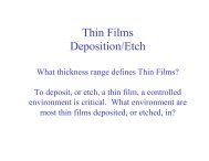
Chapter 8<br />
<strong>Photoresist</strong>s
Ch7 - Areal Image:<br />
Pattern of radiation at the<br />
surface of the wafer during<br />
exposure.<br />
To transfer a pattern, radiation<br />
changes the properties of the<br />
light sensitive material so that a<br />
replica (or a negative of the<br />
mask) of the mask is left behind.
<strong>Photoresist</strong>s (PR) or resists<br />
Three components:<br />
Resin, base material<br />
Photoactive compound (PAC)<br />
Solvent<br />
Measures of performance:<br />
• Sensitivity: amount of light energy necessary to create the<br />
chemical change in the PR<br />
• Resolution: smallest feature that can be reproduced in PR<br />
Types of PR:<br />
• Positive: i Exposed regions dissolve more quickly during<br />
development process (has better resolution than negative)<br />
• Negative: Unexposed regions dissolve more quickly during<br />
• Negative: Unexposed regions dissolve more quickly during<br />
development process
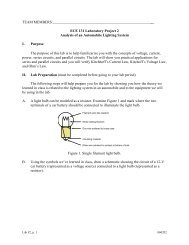
Organic Materials and Polymers<br />
Aromatic ring: 6 Carbon atoms arranged in a planar hexagonal<br />
structure with a single H atom attached to each C atom.<br />
Figure 8.1 Diagram of simple benzene aromatic ring. The delocalized pi-<br />
bond electrons are in a ring that t surrounds the nuclei. The symbol<br />
indicates the currently accepted ring notation.
Substitute:<br />
Methyl group<br />
Chlorine<br />
Additional<br />
Benzene ring<br />
Figure 8.2 Some aromatic-based compounds based on (A) single-site substitution,<br />
Figure 8.2 Some aromatic based compounds based on (A) single site substitution,<br />
(B) double-site substitution, where the first term defines the position (ortho, meta, or<br />
para) of the second substitution relative to the first, and (C) aromatic condensation.
Polymers are formed by linking together<br />
many smaller repeating units called<br />
monomers; many are C-based. One of<br />
the simplest is: polyethylene<br />
Monomer: Ethylene: C 2 H 4<br />
Polymers can be linear or branched<br />
Branching, cross-linking increases<br />
strength and density<br />
Positive Tone resist: if exposure leads to<br />
breaking polymer chains, the polymer<br />
dissolves easily in developer<br />
Negative Tone resist: if exposure leads to<br />
cross linking, polymer dissolves slowly in<br />
developer<br />
Figure 8.3 (A) Polyethylene, an<br />
example of a simple polymer. (B)<br />
Branched-chain polymers. (C)<br />
Cross-linking.
Positive resist<br />
In i-line and g-line exposures, a class of compounds, DQN<br />
DQ: diazoquinone is the PAC and the resin material is<br />
Novolac (benzene ring with substituted methyl and OH<br />
groups)<br />
-evolved from materials to make blueprints<br />
Solvents added to adjust viscosity, much of this evaporates<br />
before the exposure is done<br />
Figure 8.4 Meta-Cresol novolac, a commonly used resin<br />
material in g- and i-line applications. The basic ring<br />
structure may be repeated from 5 to 200 times.<br />
Figure 8.5 Diazo quinone (DQ), the<br />
most commonly used photoactive<br />
compound for g- and i-line<br />
applications. The right-hand ring is not<br />
an aromatic but has a double bond.
N 2 is weakly bonded and UV light will free N 2 from Carbon ring<br />
leaving behind a reactive site, more stable to move 1 Carbon<br />
outside the ring with oxygen covalently bonded to form Ketene<br />
Presence of H 2 O, final<br />
rearrangement results in<br />
carboxylic acid<br />
Figure 8.6 Photolysis and subsequent reactions of DQ upon UV exposure.
Light, water are the main drivers of this process<br />
Starting material will not dissolve in the developer; carboxylic acid,<br />
however, readily reacts with and dissolves in basic solutions (pH ><br />
7); novolac resin dissolves easily in developer<br />
Typical developer solutions are KOH or NAOH diluted with water<br />
Dark areas of the photomask will protect the resist from light and<br />
will “stay” after developing → positive image<br />
Negative resists are suited to features > 2 µm due to swelling during<br />
development; they are based on a resin of cyclized polyisoprene p and<br />
bis-aryl diazide (PAC); these compounds lose N 2 on light exposure<br />
and form free radicals that react with a site in the resin; this cross-<br />
linking produces a highly insoluble film in the developer and<br />
pattern is formed by washing away the unpolymerized resist →<br />
negative image
Contrast (γ) curves: a way to characterize resist<br />
Procedure for determining i contrast:<br />
1) spin coat a layer of PR<br />
2) Measure PR thickness<br />
3) Expose for short period of time,<br />
Exp. dose = Intensity * t exp Units: mJ/cm 2<br />
4) Immerse wafer in developer for fixed time<br />
5) Rinse and measure remaining resist<br />
Assuming positive resist and short exposure time, very little of the<br />
PAC has changed to be soluble in the developer so resist thickness<br />
is nearly the same as original thickness.<br />
Repeat experiment for increasingly larger doses and obtain a<br />
contrast curve by plotting resist thickness versus log of incident<br />
dose.
Contrast, γ , is the slope of the line at the steepest part of the curve,<br />
D o is the lowest energy needed to begin the photochemical<br />
reactions, D 100 is the energy for which all resist is removed<br />
Low exposure region<br />
Opposite behavior because resist<br />
is insoluble in developer<br />
High exposure region<br />
Figure 8.7 Contrast curves for idealized resists: (A) postitive tone and (B) negative tone.
Can be thought of as a measure of the ability of a resist to distinguish<br />
between light and dark portions of the mask<br />
γ =<br />
1<br />
log10(<br />
D100<br />
/ D<br />
Typical resists have contrast values around 2-5<br />
Another measure of performance is the critical modulation transfer<br />
function (CMTF) for the resist:<br />
CMTF D100<br />
− D0<br />
= resist D + D<br />
In terms of contrast…<br />
CMTF resist<br />
0<br />
10<br />
10<br />
)<br />
1/ γ<br />
=<br />
1/ γ<br />
Typical values are ∼0.3; provides a single number to help evaluate resolution; If<br />
MTF < CMTF, image will not be resolved.<br />
**Resolution is a combination of ability for light intensity to transfer pattern<br />
into resist and resist to distinguish that image.<br />
−1<br />
+ 1<br />
100<br />
0
Figure 8.9 Typical process flow<br />
in a photolithography step.<br />
1) Dehydration bake at 150-200 ºC in vacuum or<br />
nitrogen atmosphere for removing surface moisture<br />
on wafer to improve PR adhesion<br />
2) Wafer is primed with Hexamethyldisilazane<br />
(HMDS) - a commonly used adhesion promoter<br />
3) PR is applied by spin coating: small amount of<br />
resist dispensed on wafer and the wafer chuck<br />
(platform) spins rapidly (2000-6000 rpm)<br />
1<br />
T R<br />
∝<br />
ω<br />
4) Softbake (prebake) at ∼ 90-100 ºC will help to<br />
evaporate solvents in the resist<br />
5) Exposure to optical source<br />
6) PEB may be done to stabilize resist<br />
7) Spray coating, or immersion, of wafer in<br />
developer promotes PR removal in certain areas<br />
8) Hardbake increases adhesion of PR to underlying<br />
film to stabilize resist against the etch step or ion<br />
implantation steps
Effects of hardbake temperature;<br />
resist profile tends to reflow at<br />
high hardbake temperatures.<br />
Figure 8.11 Resist profiles of a 1-µm line and<br />
space and a large feature in SPR-2FX resist for<br />
different hardbake temperatures (courtesy<br />
Shipley).
Industrial systems are called “coat and develop tracks” where<br />
wafers move from hotplates to PR dispensing stations, spin coating<br />
platforms, etc.<br />
Figure 8.12 Top view of a photoresist<br />
processing system including cassette load<br />
and unload, resist application, bake and<br />
From:<br />
develop stations, and a central robot; more<br />
http://classoneequipment.com/equipdetails.aspEQID<br />
t / i t il modern systems are in a controlled<br />
=853<br />
environment and integrated into an exposure<br />
tool (courtesy silicon Valley Group).
Absorbance: a decrease in absorption of the photoresist after<br />
it has been exposed is called “bleaching”<br />
.<br />
Bleaching can provide a<br />
more uniform exposure<br />
because as the top layers<br />
of the resist are exposed,<br />
they become partially<br />
transparent, allowing a<br />
fuller exposure of the<br />
lower layers.<br />
Figure 8.13 Total absorbance of a layer of SPR511-A resist<br />
before and after exposure. The difference between the two<br />
curves is the actinic absorbance (courtesy Shipley).
Exposing resist over topology causes resist thickness<br />
variations; this has created a need for planarization of the<br />
layers → chemical mechanical planarization (CMP)<br />
Figure 8.14 Cross-sectional view of resist as it covers a vertical step.