Lab#2
Lab#2
Lab#2

You also want an ePaper? Increase the reach of your titles
YUMPU automatically turns print PDFs into web optimized ePapers that Google loves.
TEAM MEMBERS ______________________________________________________<br />
I. Purpose<br />
ECE 131 Laboratory Project 2<br />
Analysis of an Automobile Lighting System<br />
The purpose of this lab is to help familizarize you with the concepts of voltage, current,<br />
power, series circuits, and parallel circuits. The lab will show you practical applications for<br />
series and parallel circuits and you will verify Kirchhoff’s Current Law, Kirchoff’s Voltage Law,<br />
and Ohm’s Law.<br />
II.<br />
Lab Preparation (must be completed before going to your lab period)<br />
The following steps will help prepare you for the lab by showing you how the theory we<br />
learned in class is related to the lighting system in an automobile and to the equipment we will<br />
be using in the lab.<br />
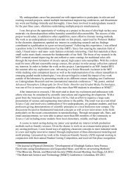
A. A light bulb can be modeled as a resistor. Examine Figure 1 and mark where the two<br />
terminals of a car battery should be connected to illuminate the light bulb.<br />
Filament (acts like resistor)<br />
Wires holding filament<br />
One wire soldered to brass case<br />
Insulating material<br />
Other wire soldered to contact at bottom of bulb<br />
Figure 1. Single filament light bulb.<br />
B. Using the symbols we’ve learned in class, draw a schematic showing the circuit of a 12-V<br />
car battery (represented as a voltage source) connected to a light bulb (represented as a<br />
resistor).<br />
Lab #2, p. 1 060202
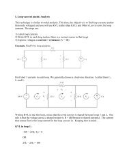
If the filament has a resistance of R,<br />
(1) How much current flows through the light bulb<br />
(2) How much power is dissipated by the light bulb<br />
(3) How much power must be provided by the battery<br />
C. Redraw your schematic, adding a switch in series with the light bulb so that you can turn<br />
the light on and off. The symbol for a switch is shown in Figure 2.<br />
Figure 2. Schematic representation of a switch.<br />
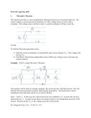
D. In the lab we will use a special “break-out box” to make it simpler for you to create your<br />
circuits. This box, shown in Figure 3, has five light bulbs, a potentiometer (variable<br />
resistor), a switch, and various terminals. Examine Figure 3 carefully.<br />
The red and black terminals in the lower left corner are for you to connect the 12-V power<br />
supply representing the car battery. The positive (+) terminal of the power supply will be<br />
connected to the red terminal on the box and the negative (–) terminal of the power supply<br />
will be connected to the black terminal on the box. This convention (using red (R) to<br />
represent + and black (B) to represent –) is used by virtually all electrical and computer<br />
engineers. Draw the symbol for a 12-V source on the upper left side of Figure 3, then show<br />
how the source should be connected to the red and black terminals.<br />
Lab #2, p. 2 060202
E. Find Single Filament Bulb #1 on the Figure 3 breakout box. The lower terminal, which is<br />
gray, is connected to the brass case of a single filament bulb. The upper terminal, which is<br />
white, is connected to the contact at the bottom of the bulb (see Figure 1). In Part D you<br />
showed how the power supply is connected to the red and black terminals on the breakout<br />
box. Using Figure 3, show the rest of the connections necessary to build the circuit you<br />
designed in Part C.<br />
Potentiometer<br />
(Variable Resistor)<br />
Dashboard Light<br />
Dual Filament Bulb #1<br />
Dual Filament Bulb #2<br />
Switch<br />
Terminals for<br />
Power Supply<br />
Single Filament Bulb #1<br />
Figure 3. Breakout box for automotive lighting system.<br />
Single Filament Bulb #2<br />
F. Suppose the single filament bulb is used for the brake light on the left rear fender of your<br />
car. You also need a brake light bulb for the right rear fender.<br />
(1) Draw a circuit showing the two bulbs connected in series to a 12-V car battery.<br />
(2) Draw a circuit showing the two bulbs connected in parallel to a 12-V car battery.<br />
Lab #2, p. 3 060202
(3) When a light bulb fails, it almost always becomes an open circuit (because the<br />
filament burns out). With this in mind, which do you think is a safer design for your<br />
automobile brake lights, the series circuit shown in part (1) or the parallel circuit<br />
shown in part (2). Justify your answer.<br />
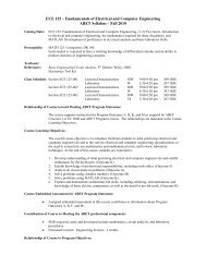
G. Using the breakout box redrawn in Figure 4, show how you would connect the elements to<br />
produce the circuit in Part F (3). Draw a 12-V source to represent the car battery and use<br />
the red and black terminals, the switch, single filament bulb #1, and single filament bulb<br />
#2.<br />
W<br />
W<br />
Bl<br />
G<br />
Potentiometer<br />
(Variable Resistor)<br />
G<br />
Dashboard Light<br />
W<br />
Y<br />
W<br />
Y<br />
G<br />
G<br />
R<br />
Dual Filament Bulb #1<br />
Dual Filament Bulb #2<br />
Switch<br />
W<br />
W<br />
B<br />
Terminals for<br />
Power Supply<br />
G<br />
Single Filament Bulb #1<br />
G<br />
Single Filament Bulb #2<br />
Figure 4. Breakout box for automotive lighting system (redrawn).<br />
Lab #2, p. 4 060202
H. If each of the single filament bulbs has a resistance of R, for the circuit in Part F (3),<br />
(1) How much current flows through single filament bulb #1<br />
(2) How much current flows through single filament bulb #2<br />
(3) How much power must be provided by the battery<br />
I. Often times a bulb will contain more than one filament. For example, an automotive light bulb<br />
may contain two filaments, one for a tail light and one for a turn signal. Figure 5 shows a dual<br />
filament automotive light bulb. Using resistors R 1 and R 2 to represent filament 1 and filament<br />
2, respectively, draw a circuit showing the two filaments connected in parallel across a 12-V<br />
source.<br />
Filament #1<br />
Filament #2<br />
One wire soldered to<br />
brass case<br />
Insulating material<br />
Contact for filament #2<br />
Contact for filament #1<br />
Figure 5. Dual filament bulb.<br />
Lab #2, p. 5 060202
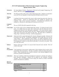
J. In addition to single filament bulbs, the breakout box has two dual filament bulbs. As shown<br />
in Figure 6, the lower terminal, which is gray (G), is connected to the brass case of the dual<br />
filament bulb while the upper terminal, which is white (W), is connected to the other end of<br />
one of the two filaments. The center terminal, which is yellow (Y), is connected to the other<br />
end of the second of the two filaments.<br />
(1) Using the switch and Figure 6, show how the 12-V supply representing the car battery<br />
can be connected to one of the two filaments on dual filament bulb #1.<br />
(2) Using the switch and Figure 7, show how the 12-V supply representing the car battery<br />
can be connected to the other of the two filaments on dual filament bulb #1.<br />
(3) Using the switch and Figure 8, show how the 12-V supply representing the car battery<br />
can be connected in parallel to both filaments on dual filament bulb #1.<br />
W<br />
W<br />
Bl<br />
G<br />
Potentiometer<br />
(Variable Resistor)<br />
G<br />
Dashboard Light<br />
W<br />
Y<br />
W<br />
Y<br />
G<br />
G<br />
R<br />
Dual Filament Bulb #1<br />
Dual Filament Bulb #2<br />
Switch<br />
W<br />
W<br />
B<br />
Terminals for<br />
Power Supply<br />
G<br />
Single Filament Bulb #1<br />
G<br />
Single Filament Bulb #2<br />
Figure 6. Breakout box for automotive lighting system (redrawn).<br />
Lab #2, p. 6 060202
W<br />
W<br />
Bl<br />
G<br />
Potentiometer<br />
(Variable Resistor)<br />
G<br />
Dashboard Light<br />
W<br />
Y<br />
W<br />
Y<br />
G<br />
G<br />
R<br />
Dual Filament Bulb #1<br />
Dual Filament Bulb #2<br />
Switch<br />
W<br />
W<br />
B<br />
Terminals for<br />
Power Supply<br />
G<br />
Single Filament Bulb #1<br />
G<br />
Single Filament Bulb #2<br />
Figure 7. Breakout box for automotive lighting system (redrawn).<br />
W<br />
W<br />
Bl<br />
G<br />
Potentiometer<br />
(Variable Resistor)<br />
G<br />
Dashboard Light<br />
W<br />
Y<br />
W<br />
Y<br />
G<br />
G<br />
R<br />
Dual Filament Bulb #1<br />
Dual Filament Bulb #2<br />
Switch<br />
W<br />
W<br />
B<br />
Terminals for<br />
Power Supply<br />
G<br />
Single Filament Bulb #1<br />
G<br />
Single Filament Bulb #2<br />
Figure 8. Breakout box for automotive lighting system (redrawn).<br />
Lab #2, p. 7 060202
K. Potentiometers (also known as “pots”) are variable resistors. These resistors contain three<br />
terminals, as shown in Figure 9 below. The potentiometer is made up of a wire winding between<br />
terminals a and b. The total resistance of the winding is a fixed value, say R ohms. Terminal c is<br />
connected to another wire that can move up and down along the winding, making contact with a<br />
single point (this wire is known as a wiper arm). The resistance between a and c (and the<br />
resistance between b and c) is dependent on the point on the winding touched by the wiper arm.<br />
Let R ac symbolize the resistance between terminals a and c, and let R bc symbolize the resistance<br />
between terminals b and c. The more winding between a and c, the larger the resistance between a<br />
and c. Note that the sum of the resistances between a and c and between b and c is R (i.e., R ac +<br />
R bc = R).<br />
a<br />
c<br />
b<br />
Figure 9. A variable resistor (or potentiometer).<br />
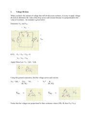
If the voltage across terminals a and b is V ab , write an expression for the voltage V cb (the<br />
voltage across terminals c and b) in terms of V ab , R, and R bc ).<br />
L. Based on your analysis in Part K, discuss how a potentiometer can be used as a voltage divider.<br />
Lab #2, p. 8 060202
M. Draw a circuit with a 12-V source connected across terminals a and b of the potentiometer and<br />
with a single element dashboard light connected across terminals b and c of the potentiometer.<br />
Discuss how moving the wiper arm of the potentiometer causes the dashboard light to dim or<br />
brighten.<br />
N. As shown in Figure 10, the breakout box contains a potentiometer and a dashboard light. The<br />
white (W), gray (G), and blue (Bl) potentiometer terminals on the breakout box correspond to<br />
terminals a, b, and c of the Figure 9 schematic, respectively. Using the switch and a 12-V<br />
source, show the connections on Figure 10 necessary to create a dashboard light with<br />
adjustable intensity.<br />
W<br />
W<br />
Bl<br />
G<br />
Potentiometer<br />
(Variable Resistor)<br />
G<br />
Dashboard Light<br />
W<br />
Y<br />
W<br />
Y<br />
G<br />
G<br />
R<br />
Dual Filament Bulb #1<br />
Dual Filament Bulb #2<br />
Switch<br />
W<br />
W<br />
B<br />
Terminals for<br />
Power Supply<br />
G<br />
Single Filament Bulb #1<br />
G<br />
Single Filament Bulb #2<br />
Figure 10. Breakout box for automotive lighting system (redrawn).<br />
Lab #2, p. 9 060202
III. Lab<br />
A. Inspect your breakout box. Is it what you expected after performing the prelab<br />
B. Inspect a single filament bulb and a dual filament bulb (the bulbs will be provided by your<br />
lab instructor – please do NOT remove the bulbs from your breakout box). Are the bulbs<br />
what you expected after performing the prelab<br />
C. With the switch open-circuited and the power supply turned off (using the power strip),<br />
wire the breakout box for a switch and single filament bulb, as shown in the wiring<br />
diagram you developed in Prelab Part E. After you complete your wiring, turn on the<br />
power supply and close the switch.<br />
(1) Measure and record the voltage across the terminals of the single-element bulb.<br />
(2) Turn off the power supply, open the switch, and remove the power supply from the<br />
circuit. You will do this by removing the wires from the power supply’s terminals,<br />
not from the red and black terminals on the breakout box (why).<br />
(3) Now insert the ammeter in the circuit. Be sure that you are using the 10A input and<br />
ask your lab instructor to inspect your circuit before reconnecting the power supply<br />
and closing the switch.<br />
(4) After the inspection but while your lab instructor is still watching, reconnect the<br />
power supply and turn it on, close the switch, and measure and record the current<br />
flowing through the bulb.<br />
(5) Open the switch, turn off the power supply, and remove the power supply as you<br />
did in Step (2).<br />
(6) Remove the ammeter from the circuit.<br />
(7) Calculate the resistance of the bulb and the power absorbed by the single filament<br />
bulb. Record your calculations.<br />
(8) How much power must the power supply generate to illuminate the single filament<br />
bulb<br />
D. With the switch open-circuited and the power supply turned off, wire the breakout box for<br />
a switch and two brake lights using the wiring diagram you developed in Prelab Part F (3).<br />
(1) Are the bulbs in series or in parallel<br />
(2) Turn on the power supply, close the switch, and measure and record the voltage<br />
across the power supply, the first brake light, and the second brake light.<br />
(3) Turn off the power supply, open the switch, and remove the power supply from the<br />
circuit (remember to do this by removing the wires from the power supply’s<br />
terminals, not from the red and black terminals on the breakout box).<br />
(4) Insert the ammeter in the circuit to measure the current flowing out of the power<br />
supply. Be sure that you are using the 10A input, and ask your lab instructor to<br />
inspect your circuit before reconnecting the power supply and closing the switch.<br />
(5) Reconnect the power supply and turn it on, close the switch, and measure and<br />
record the current flowing out of the power supply.<br />
(6) Open the switch, turn the power supply off, and remove the power supply as you<br />
did in Step (3).<br />
(7) Calculate and record the power provided by the power supply.<br />
Lab #2, p. 10 060202
(8) Insert the ammeter in the circuit to measure the current flowing through the second<br />
brake light. Be sure that you are using the 10A input, and ask your lab instructor to<br />
inspect your circuit before reconnecting the power supply and closing the switch.<br />
(9) Reconnect the power supply and turn it on, close the switch, and measure and<br />
record the current flowing through the second brake light.<br />
(10) Open the switch, turn the power supply off, and remove the power supply as you<br />
did in Step (3).<br />
(11) Calculate and record the power absorbed by the second brake light.<br />
(12) Repeat Steps (8) – (11) for the first brake light. You may need to significantly<br />
rewire your circuit to ensure that the ammeter is only measuring the current through<br />
the first brake light.<br />
E. Describe how you can use the power measurements from Part D to show conservation of<br />
power.<br />
F. Decribe how you can use the current measurements from Part D to show Kirchhoff’s<br />
Current Law.<br />
G. Using the wiring diagram from Prelab Part J (1),<br />
(1) Measure and record the voltage across the first filament of the dual filament bulb.<br />
(2) Measure and record the current through the first filament of the dual filament bulb.<br />
(3) Calculate the resistance of the filament and the power absorbed by the filament.<br />
Record your calculations<br />
H. Using the wiring diagram from Prelab Part J (2),<br />
(1) Measure and record the voltage across the second filament of the dual filament<br />
bulb.<br />
(2) Measure and record the current through the second filament of the dual filament<br />
bulb.<br />
(3) Calculate the resistance of the filament and the power absorbed by the filament.<br />
Record your calculations<br />
(4) Which of the two filaments in the bulb was brighter Is your observation consistent<br />
with your voltage and current measurements Justify your answer.<br />
I. Using your measurements in Parts G and H, calculate how much current would flow from<br />
the power supply if both filaments were connected in parallel. Also calculate the power<br />
that the power supply would have to provide. Record your calculations<br />
J. Using your wiring diagram from Prelab Part J (3), verify your calculations from Part I.<br />
Be sure to record any discrepancies in your measurements.<br />
K. Using the ohmmeter,<br />
(1) Measure and record the resistance between terminals a and b of the potentiometer.<br />
(2) Turn the potentiometer knob as far as possible counterclockwise and measure and<br />
record the resistance between terminals c and b.<br />
(3) Repeat Step (2) with the potentiometer knob turned clockwise as far as possible.<br />
(4) Repeat Step (2) with the potentiometer knob turned to three various positions<br />
between the two stops. Lightly mark each position in pencil on the breakout box.<br />
Lab #2, p. 11 060202
L. Connect the power supply across terminals a and b of the potentiometer. Switch the Fluke<br />
45 multimeter back to “volts”. With the potentiometer knob in each of the five positions<br />
described in Part K, measure and record the voltage between terminals c and b.<br />
M. Are your voltage measurements in Part L consistent with the resistance measurements you<br />
made in Part K Justify your answer.<br />
N. Construct the circuit designed in Prelab Part N. Turn the potentiometer knob and observe<br />
the dashboard bulb growing brighter or dimmer. Are your observations consistent with<br />
the theory of voltage division<br />
IV. Equipment List<br />
1 12-volt power supply capable of providing at least 60 W power (i.e., 5A current)<br />
1 Breakout box containing switch, two 1073 single-element automotive light bulbs, two<br />
1157 dual-filament automotive light bulbs, one 1003 automotive light bulb, and one<br />
100Ω, 2W potentiometer.<br />
1 Fluke 45 digital multimeter (or equivalent)<br />
Assorted banana plug leads<br />
Lab #2, p. 12 060202