Chapter 7 - Basic Aeronautics and Aerodynamics
Chapter 7 - Basic Aeronautics and Aerodynamics
Chapter 7 - Basic Aeronautics and Aerodynamics

Create successful ePaper yourself
Turn your PDF publications into a flip-book with our unique Google optimized e-Paper software.
<strong>Chapter</strong> 7 - <strong>Basic</strong> <strong>Aeronautics</strong> <strong>and</strong> <strong>Aerodynamics</strong><br />
<strong>Chapter</strong><br />
7<br />
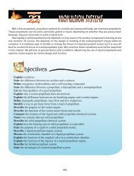
bjectives<br />
Explain the difference between aeronautics <strong>and</strong> aerodynamics.<br />
Underst<strong>and</strong> the properties of air that are important to flight.<br />
Underst<strong>and</strong> why scientists use simplifying assumptions during study.<br />
Define airfoil.<br />
Know the parts of an airfoil.<br />
Describe the concepts of relative wind, angle of attack <strong>and</strong> streamlines.<br />
Describe Bernoulli’s principle.<br />
Describe the four forces of flight.<br />
Give examples of aircraft characteristics that can improve each force.<br />
Explain how the loss of one force affects the other three forces.<br />
Describe the real world effects of viscosity <strong>and</strong> compressible airflow.<br />
Name two effects wings have on airflow not accounted for by airfoils.<br />
The Realm of Flight<br />
The science <strong>and</strong> art of flight through the atmosphere is known as aeronautics. <strong>Aerodynamics</strong>, on<br />
the other h<strong>and</strong>, is the science relating to the energy of gases in motion.<br />
To underst<strong>and</strong> the science of aeronautics <strong>and</strong> aerodynamics, you must study the air <strong>and</strong> the machine<br />
that operates in it. Once you gain an underst<strong>and</strong>ing of the machine <strong>and</strong> its environment, you can<br />
appreciate the technological marvel of flight. One has only to watch a bird in flight for a short while<br />
<strong>and</strong> it becomes obvious that this living machine is capable of using the energy of the atmosphere to<br />
defy gravity.<br />
The science of aerodynamics involves many investigations. Besides the study of airflow around<br />
an aircraft, it also includes the passage of air through a jet engine <strong>and</strong> even the expulsion of energy<br />
from a rocket motor. The common denominator of each of these examples is fluids in motion.<br />
The Composition <strong>and</strong> Properties of Air<br />
The atmosphere is a mixture of several gases. For practical purposes, in the region where most<br />
flight occurs, it is a homogeneous mixture of one-fifth oxygen <strong>and</strong> four-fifths nitrogen. The atmosphere<br />
extends upwards to about 100 miles <strong>and</strong> can be compared to a pile of blankets.<br />
179
Pressure<br />
Air at the higher altitudes is like the<br />
top blanket of the pile; it is under<br />
much less pressure than the air at<br />
lower altitudes. At the bottom of the<br />
atmosphere, say sea-level, the weight<br />
of all the layers of air above it press<br />
the bottom layer down at a pressure of<br />
0.07651 lb/ft 3 (for dry air at 59°F, 40°<br />
latitude). That gives you a st<strong>and</strong>ard<br />
day pressure of 14.7 psi, or 29.92 on<br />
a mercury barometer.<br />
Temperature<br />
Temperature is a measure of the energy within a gas. The hotter the air, the more energy it has<br />
internally, <strong>and</strong> the faster its molecules move around.<br />
The temperature of the atmosphere decreases at a rate of about 3.5° Fahrenheit, per 1,000 feet<br />
increase in altitude. This decrease in temperature continues up to about 38,000 ft MSL. You should<br />
remember, however, that the temperature of the air is under no contract to actually follow the st<strong>and</strong>ard.<br />
Sometimes, the temperature actually increases with altitude for a short distance.<br />
Density<br />
The density of air is essentially how many molecules are squeezed into a given volume. Higher<br />
density air is squeezed together more tightly than lower density air. From this, it can be assumed that<br />
air is compressible.<br />
Because the air at higher altitudes has less pressure, it is also less dense. At sea level, on a cool<br />
day, the air is dense <strong>and</strong> airplanes perform very well.<br />
Density is also related to temperature. As the air is heated, the molecules move farther apart <strong>and</strong> this<br />
means there is a decrease in density. On a hot day at a high elevation such as the airport in Leadville,<br />
CO (over 9000 ft MSL), some airplanes have difficulty taking off because the air is too thin.<br />
viscosity<br />
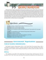
The Great Lakes biplane typifies the wonderful<br />
airplanes built in aviation’s Golden Era.<br />
Viscosity is defined as a fluid’s resistance to flow. An easy comparison would be water <strong>and</strong> honey.<br />
Honey is more viscous.<br />
Since air is a fluid, it also has a resistance to flow. This is because of (1) the attraction between the<br />
molecules of the air <strong>and</strong> (2) the attraction between the air <strong>and</strong> the molecules of whatever it touches. If<br />
180
<strong>Chapter</strong> 7 - <strong>Basic</strong> <strong>Aeronautics</strong> <strong>and</strong> <strong>Aerodynamics</strong><br />
a force is applied to air, its molecules resist<br />
a tendency to flow. The greater the density<br />
of the air, the greater the resistance.<br />
A phenomenon known as viscous drag<br />
occurs when an object is placed in the path<br />
of moving air. The mutual attraction of<br />
molecules slows the rate of flow. This form<br />
of drag is transmitted to other air molecules<br />
that are not actually touching the surface<br />
over which they are flowing.<br />
This transmission of drag is the result<br />
of a mutual attraction between molecules<br />
within the airstream, but it is not transmitted<br />
to all the air molecules. At some point away<br />
from the surface, the effect of viscous drag<br />
is lost.<br />
Viscous Drag<br />
Laminar Flow<br />
As an object moves through the<br />
air, there is a flow pattern around it.<br />
This flow pattern is either smooth<br />
or turbulent. The smooth, <strong>and</strong> more<br />
desirable flow, is known as laminar.<br />
In actual flight, an airfoil may<br />
experience both laminar <strong>and</strong> turbulent<br />
flow patterns. Aeronautical engineers<br />
are, therefore, constantly searching<br />
for ways to improve performance<br />
<strong>and</strong> laminar flow is given careful<br />
consideration in the design of new<br />
aircraft.<br />
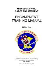
The P-51D Mustang shown here had a very efficient laminar flow wing.<br />
The Speed of Sound in Air<br />
If a pebble were dropped in a lake, ripples would spread out from the point where it impacts the water.<br />
This is a visualization of how sound waves travel away from the source that is making the sound.<br />
In this example, the rock had to push against some water molecules, <strong>and</strong> they in turn push against<br />
other molecules. If another rock were placed in exactly the same location as the first one, another wave<br />
would be created. The “sound source” of energy does this.<br />
A disturbance with enough energy to produce a sound causes a reaction that is transmitted from<br />
181
Sound Wave Radiations<br />
molecule to molecule in all directions. These collisions of molecules cause small, local pressure changes<br />
within the gas, <strong>and</strong> it appears to radiate outwardly in a series of waves from the source. The speed at<br />
which the disturbance travels in air is called the speed of sound.<br />
The Austrian physicist Ernst Mach (1838-1916) is given credit for determining the correct<br />
mathematical value for the speed of sound. His last name <strong>and</strong> the number “one” after it represents the<br />
speed of sound through a medium—as in “Mach One.”<br />
The speed of sound varies with altitude because temperature generally decreases with an increase in<br />
height. For example, the speed of sound in air is about 761 mph when the air temperature is 59° F. If the<br />
air temperature is lowered to 30°F, the speed of sound drops to approximately 692 miles per hour.<br />
In the mid-40’s, it was thought that the speed of sound couldn’t be attained. It was called the “sound<br />
barrier.” The Bell Aircraft Corporation built an airplane, called the X-1, to break this barrier. It was a<br />
known fact that a 50-caliber rifle bullet could exceed the speed of sound <strong>and</strong> the Bell engineers used this<br />
shape as the basis for the fuselage of the X-1. After extensive testing, it exceeded the speed of sound<br />
on October 14, 1947, with Air Force test pilot, Charles E. “Chuck” Yeager, at the controls.<br />
182
<strong>Chapter</strong> 7 - <strong>Basic</strong> <strong>Aeronautics</strong> <strong>and</strong> <strong>Aerodynamics</strong><br />
Airfoil—Designs that Capture<br />
the Energy of the Wind<br />
An airfoil is designed specifically to cause a dynamic reaction from the air through which it moves.<br />
Those parts of the airplane specifically designed to react with the air include the wing <strong>and</strong> tail surfaces.<br />
Likewise, propellers are airfoils by design <strong>and</strong> their rotation through the relative wind creates a “forward<br />
lift.”<br />
Airfoil Design<br />
This illustration shows the cross-section of a wing,<br />
but it could be a tail surface or a propeller because they<br />
are all essentially the same.<br />
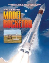
Going Supersonic! F/A 18 breaks the sound barrier.<br />
Airfoil Cross-section<br />
Leading Edge. The leading edge of an<br />
airfoil meets relative wind first. The shape at<br />
this location depends upon the intended use<br />
of the airfoil. If the airfoil is designed to be<br />
flown at high speeds, its leading edge will be<br />
sharp such as those found on the wings of<br />
jet fighters. The leading edges of the wings<br />
on slower training <strong>and</strong> pleasure-type aircraft<br />
(such as the single-engine trainers <strong>and</strong> gliders)<br />
are more rounded <strong>and</strong> thicker.<br />
Camber. Immediately behind the leading<br />
edge, there is the upper <strong>and</strong> lower camber.<br />
This curvature determines the airfoil’s<br />
thickness. Camber can be either positive or<br />
negative. Positive camber curves away from<br />
the centerline while negative camber moves<br />
toward the centerline of the airfoil.<br />
Early airfoils, such as the ones<br />
used on the Langley Aerodrome,<br />
were similar to the wings of birds. In<br />
aerodynamic terms, this means that<br />
the wing has a positive upper camber<br />
<strong>and</strong> negative lower camber.<br />
A close examination of the<br />
Wright Flyer will show that it too<br />
has a positive-upper, negative-lower<br />
camber.<br />
The Langley Aerodrome<br />
183
When the Wright brothers<br />
found that their calculations<br />
were not providing the<br />
expected lift for their<br />
gliders, they built a wind<br />
tunnel <strong>and</strong> experimented<br />
with small-scale airfoils.<br />
These experiments proved<br />
invaluable in achieving<br />
success on December 17,<br />
1903. The airfoil that was<br />
eventually used on the Flyer<br />
was only a part of their<br />
The Wright Flyer<br />
successful design. The key<br />
ingredient to their achievement was control. Others had achieved varying degrees of success with lift<br />
from primitive designs; however, the Wrights were able to control their craft once it was aloft.<br />
Trailing Edge. Whether the camber is pronounced or thin, positive or negative, the upper <strong>and</strong><br />
lower surfaces must come together at the rear of the wing. This thin junction is called the trailing edge.<br />
The trailing edge area is where the air stream rejoins after having been separated at the leading edge<br />
<strong>and</strong> directed over, <strong>and</strong> under the airfoil surface.<br />
Chord. A very important part of an airfoil is its chord. This imaginary line is shown in the<br />
illustration of the airfoil cross-section on page 177. It connects the leading with the trailing edge. It is<br />
used in the scientific explanation of several aerodynamic functions. One of the most important is the<br />
concept of angle of attack.<br />
The Relative Wind is opposite the flight path <strong>and</strong> impacts the airfoil at any angle to the chord line.<br />
Even though the air at an airport may be calm, when the airplane moves down the runway for takeoff,<br />
a “relative wind” starts blowing over the wing. At some point in the takeoff roll, the pilot increases<br />
the angle between the chord line <strong>and</strong> the relative wind. At that moment, a substantial amount of lift is<br />
created <strong>and</strong> the airplane takes flight. Pilots call this rotation.<br />
Angle of Attack. The angle created by the pilot during takeoff is known as the angle of attack.<br />
By definition, it is the angle between the chord line <strong>and</strong> the oncoming relative wind.<br />
It must be noted that angle of attack is not the same as the Angle of Incidence. The incidence angle<br />
is between the chord <strong>and</strong> the centerline of the aircraft.<br />
In the world of automobile racing, airfoils also play an important role. If a race car builder wants to<br />
improve traction, it is a common practice to mount an airfoil somewhere on the car. If properly designed<br />
<strong>and</strong> mounted, an airfoil can create a substantial amount of down force.<br />
Angle of attack is also expressed in negative terms <strong>and</strong> when a car-mounted wing is angled with its<br />
leading edge lower than its trailing edge, a “negative lift” is created. An extreme example of this is found<br />
on oval track racers. Their airfoils often cover nearly 50% of the car! Some of the most sophisticated<br />
aerodynamic designs are found on the international Gr<strong>and</strong> Prix <strong>and</strong> Indianapolis 500 race cars.<br />
184
<strong>Chapter</strong> 7 - <strong>Basic</strong> <strong>Aeronautics</strong> <strong>and</strong> <strong>Aerodynamics</strong><br />
Who is Daniel Bernoulli<br />
In 1738, Daniel Bernoulli, a Dutch-born physicist, was<br />
given credit for developing the laws that explain how a wing<br />
lifts. What Bernoulli discovered was a relationship between<br />
the pressure <strong>and</strong> speed of a fluid in motion. More specifically,<br />
as the velocity of a fluid increases, the pressure decreases.<br />
This illustration shows the flow of air, called streamlines,<br />
over an airfoil. They show air that is moving at the same<br />
velocity. Streamlines help visualize the fact that as the airfoil<br />
moves through the air, the air must go around the shape.<br />
Streamlines Around an Airfoil<br />
Because the air flow separation must have continuity, it<br />
splits at the leading edge <strong>and</strong> comes together once again at the trailing edge of the airfoil. The air that<br />
goes over the top of the airfoil must travel a greater distance than the air, which goes under the bottom;<br />
this is because the upper camber is designed to have a greater curvature.<br />
Bernoulli’s principle states, once again, “As a fluid’s speed increases, the pressure within the fluid<br />
decreases.” So the pressure of the air on top of the airfoil must be less than the pressure below. If the<br />
pressure above is less, <strong>and</strong> the pressure below is greater, the airfoil has no choice but to move upward,<br />
toward the lower pressure. It is literally a “suction” on top <strong>and</strong> “push” from underneath.<br />
To a great extent, the camber determines the amount of lift that a wing will produce at a given<br />
speed. The thicker, or more pronounced, camber generally produces the most lift because it makes the<br />
airflow travel faster over the upper surface. This accelerated flow rate produces a much lower pressure.<br />
The more negative pressure induced to the upper camber, the more lift produced. At low speeds, it is<br />
desirable to have a high-lift airfoil. This is particularly evident in STOL, or short takeoff <strong>and</strong> l<strong>and</strong>ing,<br />
aircraft.<br />
The Forces of Flight<br />
The Four Forces of Flight in Balance<br />
The four forces of flight represent<br />
centuries of study by many historic figures.<br />
Leonardo DaVinci’s detailed notes of his<br />
nature observations lead to the idea that lift<br />
could be produced by flowing air. Sir Isaac<br />
Newton’s study of classical mechanics led<br />
to the mathematical explanations of gravity.<br />
Octave Chanute <strong>and</strong> Otto Lilienthal developed<br />
mathematical equations for lift. These were<br />
used although later disproved by the Wright<br />
brothers.<br />
These forces are lift, drag, thrust, <strong>and</strong><br />
weight. By definition, the lift force acts perpendicular<br />
to the relative wind or the line of flight.<br />
185
The drag force acts parallel to the relative wind. The thrust force usually acts parallel to the centerline<br />
of the fuselage <strong>and</strong> the weight always acts in the direction of gravity.<br />
First, think about the forces that oppose one another: lift vs. weight, thrust vs. drag. If you can get<br />
more lift <strong>and</strong> less weight, then your air vehicle will be able to fly. More thrust <strong>and</strong> less drag would allow<br />
the airplane to move forward.<br />
Taking Flight<br />
In this section we are ready to take the next step in underst<strong>and</strong>ing how airplanes fly. First, we must<br />
introduce the rest of the aircraft surrounding the airfoil. Without getting too deep into parts, we can<br />
add a third dimension to the airfoil <strong>and</strong><br />
get a wing.<br />
In the photo here, the airplane is in<br />
straight-<strong>and</strong>-level, unaccelerated flight.<br />
That means nothing is changing. It does<br />
not accelerate, go up, down, or turn.<br />
This, of course, is another simplifying<br />
assumption.<br />
In straight-<strong>and</strong>-level, unaccelerated<br />
flight the thrust force balances the drag<br />
force <strong>and</strong> the lift force balances the<br />
weight. More thrust than drag would make<br />
the airplane accelerate. More lift than<br />
weight would mean the aircraft would<br />
climb in altitude.<br />
Early biplanes had a great deal of lift <strong>and</strong> a great deal of drag. (EAA)<br />
Vectors<br />
A vector is a graphic mathematical illustration showing both direction <strong>and</strong> magnitude. There is a<br />
force moving in a vertical direction from the wing. This is an illustration of lift. The amount of lift<br />
being produced is the magnitude <strong>and</strong> its direction is upward.<br />
Lift Overcomes Weight<br />
It is obvious that increased lift <strong>and</strong> decreased weight are objectives in both the designing <strong>and</strong> flying<br />
of aircraft.<br />
Lift can be increased, as mentioned before, by changing the camber, or curvature, of the airfoil<br />
shape of the wing. This type of lift is called Induced Lift because of the induced lower pressure on the<br />
top of the wing due to the camber.<br />
Also important is the angle of the wing as it encounters the relative wind. That, we learned earlier,<br />
was called angle of attack. Lift is increased as the angle of attack is increased for two reasons. First, as the<br />
186
<strong>Chapter</strong> 7 - <strong>Basic</strong> <strong>Aeronautics</strong> <strong>and</strong> <strong>Aerodynamics</strong><br />
Lift <strong>and</strong> Angle of Attack<br />
angle is increased relative to<br />
the wind, the air has to go<br />
a further distance over the<br />
top of the wing. That means<br />
a lower pressure above the<br />
wing <strong>and</strong> therefore, greater<br />
induced lift. Secondly,<br />
because there is more<br />
relative wind striking the<br />
wing’s bottom surface at<br />
higher angles of attack,<br />
the pressure created on the<br />
wing’s bottom surface is<br />
higher. This is the same<br />
feeling you get when you<br />
NASA’s Dryden Flight Research Center, Edwards, California, is using this modified F-18 aircraft to explore an area of flight<br />
called angle of attack. During maneuvers, pilots often fly at extreme angles of attack with the nose pitched up while the<br />
aircraft continues in the original direction. This can lead to conditions in which the airflow becomes separated from the<br />
airfoils, resulting in insufficient lift to maintain altitude or control. This project by NASA is creating a data base on<br />
aerodynamics at high angles of attack to help engineers <strong>and</strong> designers develop more maneuverable aircraft in the future.<br />
A thrust vectoring system has been installed on the F-18’s two engine exhaust nozzles to redirect the exhaust flow to enhance<br />
control <strong>and</strong> maneuverability for this research project. The thrust vectoring system allows the research aircraft to fly at steep<br />
angles of attack for long periods of time to collect aerodynamic data. Future aircraft to benefit from this program are<br />
expected to be highly maneuverable fighters, hypersonic vehicles <strong>and</strong> high performance civilian aircraft.<br />
187
put your h<strong>and</strong> out of the car window while driving. Because the dynamic pressure of the air on the<br />
lower h<strong>and</strong> surface causes it.<br />
Notice that there is a large increase in lift as angle of attack is increased. This is because changing<br />
angle of attack gains you both induced <strong>and</strong> dynamic lift. It should come as no surprise to you that the<br />
lift produced by the wing also depends upon the air.<br />
Remember the air’s characteristics of pressure, temperature, density, <strong>and</strong> viscosity Each can affect<br />
the ability of a wing to create lift. High-pressure air at sea level is more dense than at higher altitudes.<br />
Colder air is more dense than hotter air. Denser air flowing over the wing means more mass. More mass<br />
means more molecules <strong>and</strong> this translates to greater lift.<br />
Weight<br />
Since weight directly<br />
opposes lift in straight<strong>and</strong>-level,<br />
unaccelerated<br />
flight, weight is a problem<br />
to be overcome. How is<br />
the problem of weight<br />
managed First of all, the<br />
airplane must be constructed<br />
of the lightest-weight<br />
materials that can be used.<br />
Today, most airplanes are<br />
built of aluminum alloys.<br />
These are used extensively<br />
in aircraft construction<br />
because of their strength<br />
<strong>and</strong> light weight. The use<br />
of composite materials<br />
is making an impact too.<br />
Composites can be shaped<br />
It’s amazing how this much weight can fly! (EAA)<br />
easily <strong>and</strong> some have<br />
strength that exceed metals.<br />
The weight of the airplane’s cargo also receives very careful consideration. Each airplane has a total<br />
weight limitation called the maximum gross weight. Anything above this limit is considered unsafe<br />
for flight. It is possible to keep putting luggage or other cargo into an airplane until it is so heavy it<br />
will not fly. Since the pilot cannot put the airplane on a scale to make certain that the airplane is within<br />
its weight limits, another approach must be used. This approach is for the pilot to consult documents<br />
produced by the manufacturer of the airplane. These documents (which must remain in the airplane)<br />
will contain the maximum gross weight <strong>and</strong> the empty weight. All the pilot has to do is subtract the<br />
empty weight from the maximum allowable weight to find out how many pounds may be loaded into<br />
the airplane. This is called the Useful Load.<br />
188
<strong>Chapter</strong> 7 - <strong>Basic</strong> <strong>Aeronautics</strong> <strong>and</strong> <strong>Aerodynamics</strong><br />
Friction Drag<br />
189<br />
Thrust <strong>and</strong> Drag<br />
Thrust is the force that<br />
propels the aircraft forward.<br />
The ultimate goal is to design<br />
an engine that produces a lot<br />
of thrust on a machine that<br />
weighs very little. This gives<br />
the pilot more speed, more<br />
lift, <strong>and</strong> less weight.<br />
Drag is the force that opposes<br />
all motion through the<br />
atmosphere <strong>and</strong> is parallel to the direction of the relative wind. Drag is created because of the airplane’s<br />
motion through the air.<br />
There are many components of drag. Part of the total drag is caused by the friction of air particles<br />
rubbing against the parts of the airplane. An illustration of Friction Drag is dragging your h<strong>and</strong> across<br />
a smooth surface <strong>and</strong> then a piece of s<strong>and</strong>paper. The movement of your h<strong>and</strong> over the s<strong>and</strong>paper simulates<br />
the effects of friction drag.<br />
Another type is Form Drag. The very shape of something may create turbulence as the aircraft<br />
flies. In this turbulence are pockets of low- <strong>and</strong> high-pressure air leaving a wake behind the airplane.<br />
This turbulence disrupts the flow of air over the wing <strong>and</strong> reduces how well it creates lift. The smooth,<br />
low-pressure air over the top of the airfoil is pushed by the turbulence at the trailing edge. This pushing<br />
back upstream against the flow slows the airflow over the airfoil <strong>and</strong> causes the streamlines to separate<br />
away from the wing. As a result, a force vector trails the airplane <strong>and</strong> works against its forward motion.<br />
Streamlining the aircraft will reduce form drag. Parts of an aircraft which do not lend themselves to<br />
streamlining are enclosed in covers called fairings.<br />
Drag is almost always detrimental to aircraft performance. Because it works to slow the airplane<br />
as it moves through the air, the engine<br />
must make more thrust to go faster. More<br />
thrust usually means a bigger engine <strong>and</strong><br />
more weight.<br />
Sometimes, however, drag is useful.<br />
When you want to slow down quickly<br />
you can deploy a speedbrake. This is<br />
usually a big plate that sticks out into the<br />
wind <strong>and</strong> creates an enormous amount of<br />
form drag. In a dogfight, the speedbrake<br />
can be used to quickly slow down <strong>and</strong><br />
force your enemy to fly past you.<br />
Airliners also use speed brakes to<br />
slow their airspeed in preparation for<br />
l<strong>and</strong>ing.<br />
In the old days there were wires, wings, large front ends <strong>and</strong> the pilot’s<br />
head sticking out in the wind. All of these created a great deal of drag.<br />
(San Diego Aerospace Museum)
Real World Lift <strong>and</strong> Weight<br />
The last few pages defined the four forces of flight. Now, let’s talk about them in practical terms,<br />
in the real world.<br />
If the atmosphere <strong>and</strong> its characteristics are what allow us to fly <strong>and</strong> we change those, then our<br />
forces of flight must be affected. Additionally, if we remove some of the simplifying assumptions <strong>and</strong><br />
start looking at the whole airplane in flight, we will see that there is more to flying than we thought<br />
earlier.<br />
Lift was broken down into induced <strong>and</strong> dynamic lift components. Induced lift came from the lowpressure<br />
air on the top of the wing <strong>and</strong> dynamic lift came from the high-pressure air on the bottom.<br />
Here are two examples of how the lift force works in the real world.<br />
Turbulence. Air flowing over the surface of an airfoil is rarely very smooth. Streamlines do<br />
as the air separates around the wing, but those<br />
streamlines are not very smooth close to the surface<br />
of the aircraft. This is because air is not really<br />
viscous. As it flows over the wing’s surface it scrapes<br />
against the rough metal <strong>and</strong> is slowed down <strong>and</strong><br />
churned up. The churning of air is called turbulence<br />
<strong>and</strong> reduces the efficiency of the airfoil. Therefore,<br />
the lift created by the cambered wing is somewhat<br />
less than the ideal design prediction.<br />
Stalls. There is a point where the streamlines,<br />
located in the boundary layer of air right next to the<br />
wing’s surface, will separate from the airfoil. Once<br />
separation occurs, the air begins to flow more<br />
An airfoil approaching <strong>and</strong> entering a stall.<br />
190<br />
There are 4 forces at work all the<br />
time in every airplane. (EAA)<br />
form slowly <strong>and</strong> the lift producing low-pressure on the top<br />
of the wing is lost. The aircraft begins to sink <strong>and</strong>, if the<br />
stall becomes serious enough, departs controlled flight <strong>and</strong><br />
plummets to the earth.<br />
Aeronautical engineers try to design aircraft that stall<br />
predictably. They design the wings <strong>and</strong> fuselage so that the<br />
burbling of air shakes the aircraft <strong>and</strong> tells the pilot that a stall<br />
is imminent. When that cannot be done, they build mechanical<br />
<strong>and</strong> electronic devices that warn the pilot of the stall. And if<br />
all else fails, they try to make the stall easily recoverable so<br />
that the pilot can regain control of the aircraft.<br />
You might wonder why the force of power from the engine<br />
couldn’t take the place of the loss of lift from the airfoil. Very<br />
simply, there just isn’t enough of this force available from a<br />
conventional aircraft’s engine. Some of the more powerful<br />
jet fighter <strong>and</strong> aerobatic sport airplanes can, for a short time
<strong>Chapter</strong> 7 - <strong>Basic</strong> <strong>Aeronautics</strong> <strong>and</strong> <strong>Aerodynamics</strong><br />
<strong>and</strong> distance, climb straight up without any significant help from their airfoils, but these airplanes will<br />
eventually stall <strong>and</strong> start to fall toward earth.<br />
Weight Distribution. Gravity, or weight, always pulls the aircraft toward the earth, but its location<br />
in the air vehicle is extremely important. Here is an example of how the weight force can affect flight<br />
in the real world. Where the weight, or useful load, is placed in the airplane has a pronounced effect<br />
on how well an airplane will fly. Recall that a moment is created when you exert a force on a body at<br />
some distance from its center of gravity For an airplane that means it would rotate around the center<br />
of gravity in the direction of the moment. The pilot would have to use the control stick to counter the<br />
rotation. The danger of poorly placed weight in the aircraft is that the control surfaces may eventually not<br />
be able to counter the rotation. This would cause the aircraft to fly out of control. Although flight out of<br />
control is sometimes fun in a stunt plane, airline passengers <strong>and</strong> attendants generally frown upon it.<br />
Real World Thrust <strong>and</strong> Drag<br />
If the ideal were possible, our air vehicles would have infinite thrust <strong>and</strong> negligent drag. You could<br />
go as fast as desired in any direction <strong>and</strong> never slow down if you did not want to. Of course, this is not<br />
the case in the real world. Thrust from an engine has some limitations <strong>and</strong> can be used to the aircraft’s<br />
advantage as these examples show.<br />
Thrust Vectoring. Thrust on an aircraft is normally used to generate forward motion through the<br />
air so that the airfoil-shaped wings can develop enough lift to counter the aircraft’s weight. If the thrust<br />
force could be pointed in any direction then it could assist in maneuvering as well. That is what thrust<br />
vectoring allows.<br />
Engines are designed<br />
so that their thrust forces<br />
can be pointed along a<br />
direction other than the<br />
aircraft’s longitudinal axis.<br />
This is done by pointing<br />
the engine’s exhaust using<br />
mechanically driven plates,<br />
or special exhaust ports,<br />
called directional nozzles.<br />
Thrust vectoring can be<br />
used to assist lift, reduce the<br />
chance of a stall, or allow the<br />
aircraft to fly at extremely<br />
Wingtip Vortices Causing Induced Drag<br />
high angles of attack <strong>and</strong><br />
very slowly. This might allow the use of very short runways or make a jet fighter very maneuverable.<br />
Like the other forces, drag becomes a greater problem as our assumptions are eliminated <strong>and</strong> we consider<br />
the whole aircraft. Here is an example of a real world drag effect.<br />
Induced Drag. If lift always acted in an upward direction it would be ideal because it would always<br />
191
help us get to a higher altitude.<br />
The flow across a wing does not move only from the leading edge to the trailing edge. It also moves<br />
toward the wingtip <strong>and</strong>, sometimes, toward<br />
the fuselage. This spanwise flow on<br />
the top of the wing eventually must join<br />
the spanwise flow on the bottom of the<br />
wing. When they do, they form a swirling<br />
vortex. This vortex causes the lift<br />
vector of the wing to be slanted toward<br />
the rear of the aircraft. The slant results<br />
in a component of the lift vector pointing<br />
in the same direction as the drag vector.<br />
This component of lift adds to the drag<br />
<strong>and</strong> is called the induced drag.<br />
The winglets on this Learjet help reduce induced drag.<br />
For flight at slow speeds, below about 260 knots, air was assumed to be an incompressible fluid.<br />
However, as speed increases, air at the leading edges of the vehicle can actually be compressed. Airflow<br />
over the surfaces is no longer represented by smooth orderly streamlines. The air is simply moving so<br />
fast that it cannot turn around edges very easily. Instead, at leading edges it compresses <strong>and</strong> at trailing<br />
edges it exp<strong>and</strong>s.<br />
Supersonic Flow<br />
Supersonic <strong>Aerodynamics</strong><br />
When an airplane flies at subsonic speeds the air ahead is “warned” of the airplane’s approach by a<br />
pressure change in front of the aircraft. Remember the pebble dropped in the pond creating a wave that<br />
tells the rest of the water to move out of the way That wave in the air moves at the speed of sound,<br />
or “Mach One.”<br />
The pebble-pond analogy provides a very good picture of what is happening when an airplane flies<br />
at supersonic speeds. If a person drops pebbles into a smooth pond, each pebble will make a wave.<br />
This would be similar to the pattern of sound waves made by the aircraft’s engine as it sits still on the<br />
airfield.<br />
Now suppose we start dropping the pebbles one each second as we run along the bank. Each pebble<br />
still produces a circular wave, but the circles are crowded together on the side toward which we are<br />
moving. If we now move around the pond at a speed greater than the wave’s speed, the pattern looks<br />
different than those previously formed. Smaller circles, or those made more recently, are no longer<br />
completely inside the next larger ones. Now all the circles are jammed into a wedge-shaped region.<br />
192
<strong>Chapter</strong> 7 - <strong>Basic</strong> <strong>Aeronautics</strong> <strong>and</strong> <strong>Aerodynamics</strong><br />
This is similar to the sound-pressure wave pattern for an airplane flying at supersonic airspeeds.<br />
The leading edges of the airplane are a continuous disturbance in the air that leaves behind a wedge<br />
shaped wave.<br />
A ring of condensation occurs in the wave as this F-14 goes supersonic.<br />
(US Navy)<br />
193<br />
This wave pattern would be similar<br />
to the pattern of engine sound as the<br />
airplane flies at subsonic airspeeds. It<br />
also is the pattern made by the pressure<br />
change at the aircraft’s leading edges.<br />
At the leading edges the air is being<br />
pushed forward <strong>and</strong> this push is sent<br />
upstream of the airplane at the speed<br />
of sound, telling the rest of the air to<br />
get out of the way. The air ahead of<br />
the airplane is warned of the arrival,<br />
<strong>and</strong> the warning time is decreased as<br />
the airplane’s speed approaches the<br />
speed of sound. The warning time is<br />
zero when the airplane flies at Mach<br />
One, <strong>and</strong> has a wave pattern.<br />
If the airplane travels at supersonic<br />
speeds, the air ahead receives no<br />
warning of the airplane’s approach<br />
because the airplane is outspeeding its<br />
own pressure wave. Because the air is<br />
unprepared for the airplane’s arrival, it must move aside abruptly to let the airplane pass. This sudden<br />
displacement <strong>and</strong> resulting wedge shaped wave is called a shock wave.<br />
There are two types of shock waves. Those formed when the air must move aside as a leading edge<br />
passes <strong>and</strong> those formed when the air must fill back in as the trailing edge passes. The first is called a<br />
compression wave <strong>and</strong> the second an expansion wave.<br />
Supersonic aerodynamics requires different designs than those used on subsonic aircraft. This<br />
is a conflict with the fact that our aircraft still have to take off <strong>and</strong> l<strong>and</strong>, <strong>and</strong> those are usually done<br />
subsonic.<br />
Wave Drag. When air flows across a shock wave it undergoes a change in temperature, pressure,<br />
<strong>and</strong> velocity. These changes result in another component of drag called wave drag. Although the exact<br />
description of this drag is complex, it is really the result of lost energy.<br />
The air that moves across the shock waves is being violently altered. These changes take some energy<br />
to produce, since you never get something for nothing. The loss in energy is depicted as additional drag<br />
on the air vehicle that would require more thrust (positive energy) to overcome.<br />
The Concorde aircraft daily took passengers across the Atlantic Ocean at a speed of Mach 2.<br />
They sat enjoying the comfort of first class for a period of three hours. All this time, all the violent<br />
forces of supersonic flight were present, but the passengers were not aware of it. Isn’t this wonderful<br />
technology!!
• aeronautics <strong>and</strong> aerodynamics<br />
• properties <strong>and</strong> characteristics of gases: pressure, temperature, density, viscosity<br />
• laminar vs turbulent air flow<br />
• Mach number, speed of sound, supersonic<br />
• airfoil design: leading edge, camber, trailing edge, chord<br />
• relative wind <strong>and</strong> angle of attack<br />
• Bernoulli’s principle<br />
• four forces of flight: lift, drag, thrust, weight<br />
• induced lift <strong>and</strong> dynamic lift<br />
• useful load <strong>and</strong> load distribution<br />
• types of drag: friction drag, form drag, induced drag, wave drag<br />
• turbulence<br />
• stall<br />
• thrust vectoring<br />
• shock wave, compression wave, expansion wave<br />
MATCHING<br />
1. Movement of objects through the atmosphere<br />
2. Science relating to the energy of gases in motion<br />
3. Decreases with an increase in altitude<br />
4. Measure of how much energy the gas has<br />
5. The measure of how many molecules are squeezed into<br />
a defined space<br />
6. Resistance to the flow of a liquid or gas<br />
7. The smooth or rough flow of air over an object<br />
8. The ratio of the speed of an object to the speed of sound in air<br />
a. pressure<br />
b. temperature<br />
c. laminar or turbulent<br />
flow<br />
d. viscosity<br />
e. aeronautics<br />
f. Mach number<br />
g. aerodynamics<br />
h. density<br />
194
<strong>Chapter</strong> 7 - <strong>Basic</strong> <strong>Aeronautics</strong> <strong>and</strong> <strong>Aerodynamics</strong><br />
FILL IN THE BLANKS<br />
9. The part of the airfoil that meets the air first is the _________.<br />
10. The area determining the airfoil’s thickness <strong>and</strong> thus its lift is the _________.<br />
11. The _________ is the rear junction where the upper <strong>and</strong> lower parts of the airfoil meet.<br />
12. The _________ is the imaginary part of the airfoil that is the starting point for designing an<br />
airfoil in cross-section.<br />
13. Ideally, when a plane is in smooth flight, the force of the total lift equals the force of the total<br />
_________ <strong>and</strong> the force of _________ equals the force of drag.<br />
14. Lift <strong>and</strong> weight are in opposition to each other. Induced lift can be increased by changing the<br />
_________ of the _________.<br />
15. A _________ occurs when lift is destroyed <strong>and</strong> the force of weight takes over.<br />
16. The sudden displacement of air <strong>and</strong> the resulting wedge-shaped wave is called a ____________<br />
__________.<br />
17. Each airplane has a total weight limitation called _________.<br />
18. If a pilot subtracts the empty weight from the maximum gross weight the result is how many<br />
pounds can be loaded into the airplane. This is called the _________.<br />
TRUE OR FALSE<br />
19. Mach is the ratio of the speed of an object to the speed of sound in air.<br />
20. All fluids possess viscosity, which is a resistance to flow, but air is not included here.<br />
21. Slowing the flow rate is known as viscous drag.<br />
22. On an in-flight aircraft, laminar <strong>and</strong> turbulent flow are found at the same locations.<br />
23. The angle formed by the airfoil chord <strong>and</strong> the relative wind direction is the angle of attack.<br />
24. Induced lift is caused by the angle of attack.<br />
25. Dynamic lift is caused by camber.<br />
26. Positive atmospheric pressure at the bottom of the wing only increases the induced lift.<br />
27. Generally, the less dense the air, the less lift is available.<br />
SHORT ANSWER<br />
28. In one sentence, define relative wind, including the words speed, direction, <strong>and</strong> lift.<br />
29. What’s the difference between airspeed <strong>and</strong> ground speed<br />
30.. If drag is decreased, what happens to thrust<br />
31. Name two ways that drag can be decreased.<br />
32. What is unique about supersonic aerodynamics<br />
195