typical specifications nested parshall flumes - Plasti-Fab, Inc.
typical specifications nested parshall flumes - Plasti-Fab, Inc.
typical specifications nested parshall flumes - Plasti-Fab, Inc.

Create successful ePaper yourself
Turn your PDF publications into a flip-book with our unique Google optimized e-Paper software.
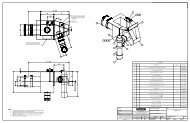
5. An integral molded track and a stainless steel ground plate for characterized capacitance<br />
probe. ** (required for both <strong>flumes</strong>)<br />
6. Inlet and/or outlet adapter to provide transition between a pipe and the larger flume.<br />
7. Inlet and/or outlet bulkheads or wingwalls to transition flow between the flume and channel.<br />
8. Recessed cavity for pressure probe with clips for holding probe and cable. Liftout<br />
bracket for pressure probe (used on larger <strong>flumes</strong>). (required for both <strong>flumes</strong>)<br />
The Parshall flume shall be equipped with a molded in head gage graduated in 100ths of a foot and<br />
centimeters.<br />
Typical physical properties shall be:<br />
Tensile strength<br />
14,000 psi<br />
Percent elongation l.65%<br />
Flexural strength<br />
25,000 psi<br />
Flexural modulus<br />
0.90 x 10 6 psi<br />
Barcol hardness 30<br />
Flume dimensions shall be within plus or minus l/16th inch for <strong>flumes</strong> 12" and smaller. For 18" to 24"<br />
<strong>flumes</strong> the tolerance shall be plus or minus 3/32nd inch in the throat and plus or minus 1/8 inch<br />
elsewhere. Flumes 30" through 48" shall be plus or minus 1/8" in the throat and plus or minus 1/4"<br />
elsewhere.<br />
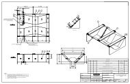
INSTALLATION SUGGESTIONS FOR NESTED FLUMES<br />
1) The flume(s) should be installed level end-to-end and side-to-side.<br />
2) Place the flume to be <strong>nested</strong> so that flat section of throat rests on throat of larger unit.<br />
3) The leading edge of the throat section on both <strong>flumes</strong> should be aligned. (See print).<br />
4) At the factory, a bead of silicon sealant has been placed between the flanges, bulkhead and<br />
other contacting surfaces of the insert flume to provide a water tight seal.<br />
5) If desired, the space between the side walls of the two <strong>flumes</strong> may be filled with sand and<br />
covered with a layer of breakable grout to help prevent water collecting between <strong>flumes</strong>.<br />
6) Please note that these <strong>flumes</strong> are designed to be freestanding, and require no additional external<br />
support in order to maintain their dimensional integrity during operation.<br />
The flume shall be as manufactured by <strong>Plasti</strong>-<strong>Fab</strong>, <strong>Inc</strong>. of Tualatin, Oregon.<br />
Please consult your local representative or contact <strong>Plasti</strong>-<strong>Fab</strong>, <strong>Inc</strong>., PO Box 100, Tualatin, Oregon, 97062.<br />
Ph: 503-692-5460 Fax: 503-692-1145 e-mail: sales@plasti-fab.com web: www.plasti-fab.com<br />
Page 2 of 2