LPCA 055-060-070-075-085-090-100-115 125-135-150-170HMB
LPCA 055-060-070-075-085-090-100-115 125-135-150-170HMB
LPCA 055-060-070-075-085-090-100-115 125-135-150-170HMB

Create successful ePaper yourself
Turn your PDF publications into a flip-book with our unique Google optimized e-Paper software.
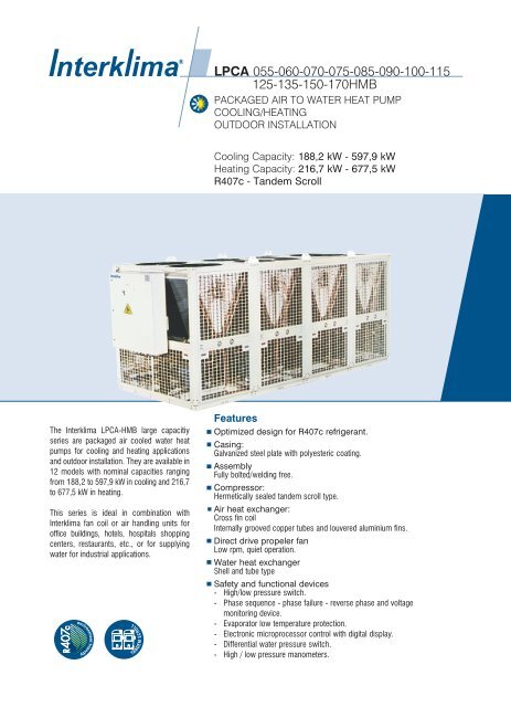
<strong>LPCA</strong> <strong>055</strong>-<strong>060</strong>-<strong>070</strong>-<strong>075</strong>-<strong>085</strong>-<strong>090</strong>-<strong>100</strong>-<strong>115</strong><br />
<strong>125</strong>-<strong>135</strong>-<strong>150</strong>-<strong>170HMB</strong><br />
PACKAGED AIR TO WATER HEAT PUMP<br />
COOLING/HEATING<br />
OUTDOOR INSTALLATION<br />
Cooling Capacity: 188,2 kW - 597,9 kW<br />
Heating Capacity: 216,7 kW - 677,5 kW<br />
R407c - Tandem Scroll<br />
The Interklima <strong>LPCA</strong>-HMB large capacitiy<br />
series are packaged air cooled water heat<br />
pumps for cooling and heating applications<br />
and outdoor installation. They are available in<br />
12 models with nominal capacities ranging<br />
from 188,2 to 597,9 kW in cooling and 216,7<br />
to 677,5 kW in heating.<br />
This series is ideal in combination with<br />
Interklima fan coil or air handling units for<br />
office buildings, hotels, hospitals shopping<br />
centers, restaurants, etc., or for supplying<br />
water for industrial applications.<br />
SCROLL<br />
TAN DE M<br />
Features<br />
Optimized design for R407c refrigerant.<br />
Casing:<br />
Galvanized steel plate with polyesteric coating.<br />
Assembly<br />
Fully bolted/welding free.<br />
Compressor:<br />
Hermetically sealed tandem scroll type.<br />
Air heat exchanger:<br />
Cross fin coil<br />
Internally grooved copper tubes and louvered aluminium fins.<br />
Direct drive propeler fan<br />
Low rpm, quiet operation.<br />
Water heat exchanger<br />
Shell and tube type<br />
Safety and functional devices<br />
- High/low pressure switch.<br />
- Phase sequence - phase failure - reverse phase and voltage<br />
monitoring device.<br />
- Evaporator low temperature protection.<br />
- Electronic microprocessor control with digital display.<br />
- Differential water pressure switch.<br />
- High / low pressure manometers.
NOMENCLATURE<br />
1 Range<br />
S-small M-mid L-large R-screw-series<br />
2 Packaged Chiller Air-cooled<br />
PCA<br />
3 Model numbers<br />
<strong>055</strong>-<strong>060</strong>-<strong>070</strong>-<strong>075</strong>-080-<strong>085</strong>-<strong>090</strong>-095-<strong>100</strong>-105-110-<strong>115</strong>-120-<br />
<strong>125</strong>-<strong>135</strong>-140-<strong>150</strong>-160-170-190<br />
4 Cool / Heat Model<br />
R-cooling only H-heat pump<br />
5 Compressor type<br />
S-scroll M-tandem scroll R-reciprocating<br />
T-twin screw<br />
6 Refrigerant type<br />
A-R22 B-R407c<br />
7 Electrical Characteristic<br />
-1 Single phase -Ommited Three phase
Contents<br />
1. Technical Description<br />
2. Specifications<br />
3. Capacity Tables<br />
4. Water Pressure<br />
Drop Curves<br />
5. Operation Range<br />
6. Sound Data<br />
7. Outlook Drawings<br />
8. Refrigerant Circuit Diagrams<br />
9. Wiring Diagrams<br />
10. Installation<br />
11. Guide Specifications<br />
Interklima Hydronic systems<br />
<strong>LPCA</strong> <strong>055</strong>-<strong>170HMB</strong> ñ R407c/Tandem Scroll 3
1. Technical Description<br />
General<br />
The <strong>LPCA</strong>-HMB series air-cooled water heat pumps consists of<br />
12 models covering capacities from 188,2 up to 597,9 KW in<br />
cooling and 216,7 up to 677,5kW in heatng.<br />
It is the end result of a thorough study, and accurate design by<br />
experienced Interklima research and development teams, to<br />
develop a large size chiller series with compact shape, high<br />
performance, and reliability of the highest quality standards.<br />
This series meets the highest levels of aesthetic and technical<br />
requirements using the latest technological innovations, including<br />
environmentally friendly R407c that is chlorine free and has zero<br />
ozone depletion potential. <strong>LPCA</strong>-HMB units are therefore ideal for<br />
installation in urban environments due to their elegant design,<br />
selected materials and low operating sound levels.<br />
Casing<br />
All units use metal parts fabricated from heavy gauge galvanized<br />
steel sheets, formed to ensure maximum rigidity that guarantees and<br />
preserves the units operation during the years. After fabrication these<br />
are degreased, phosphatised, and electrostatically powder coated<br />
with an epoxy-polyester RAL 9002 coating of a thickness 60-70 Ì.<br />
This fully automatic process ensures superior corrosion resistance<br />
against the most aggressive ambient conditions. The treatment can<br />
successfully withstand a salt spray test of 500 hours, according to<br />
ASTM B-117. All components are assembled together using bolts<br />
thus avoiding the need for welding which may harm the galvanization<br />
of the steel, and ensures that the whole assembly can fully withstand<br />
adverse weather conditions<br />
The compact footprint of the unit arises from detailed study and<br />
design by our engineering teams and results in a machine, which<br />
fits easily in restricted areas and is simple and easy to install and<br />
maintain, and has been designed with special fittings for easy<br />
transport and lifting.<br />
Removable side panels are used to permit access only to<br />
authorized personnel to internal components of the unit for<br />
inspection and maintenance. Electrical and electronic equipment<br />
and components for proper unit operation are located in a weather<br />
proof (IP 55) electrical panel with access only via a special key.<br />
Compressor<br />
All units use low-noise, maintenance free, Hermetic Tandem Scroll<br />
compressors with low vibration levels, specially optimized for use<br />
with R407c refrigerant, selected from world class suppliers. They are<br />
equipped with a crankcase electrical heater for the oil, and are<br />
internally protected against potential overloading or electrical spikes.<br />
The compressors are mounted on special antivibration rubber<br />
mounts to eliminate vibration from the unit’s operation.<br />
Air heat exchanger coil<br />
All unit air heat exchangers are manufactured from high quality<br />
copper inner grooved seamless tubes according to ASTM B-280,<br />
having an outside diameter of 9,52 mm (3/8"). The fins are<br />
manufactured from aluminium and form the secondary extended<br />
heat transfer surface. The fins are continuous across the heat<br />
exchanger and are fabricated in high precision dedicated press<br />
lines. The fin surface is waffle formed, so as to increase the fin<br />
rigidity, and has special louvers that help increase heat transfer. The<br />
combination of internally grooved Copper-tubing and louvered fins<br />
has resulted in a heat transfer performance 30% superior to that of<br />
a conventional coil for this particular application. The assembly of<br />
the finned pack is achieved by mechanical expansion of the tubes in<br />
such a way as to form a perfect mechanical bond with the fins. For<br />
this purpose, the fin holes have a peripheral extrusion (collar) of<br />
adjustable height. This extrusion serves to define the distance<br />
between fins (and consequently the total heat transfer surface) and<br />
to ensure perfect contact of the fins to the tubes.<br />
Alternative fin materials are available upon request such as epoxy<br />
– coated aluminium or copper for applications in especially<br />
aggressive environments.<br />
Water heat exchanger<br />
All units are equipped with a Shell and Tube water –direct<br />
expansion type evaporator that has multiple cooling circuits, one<br />
for each independent refrigerant circuit. The casing is of steel and<br />
the internal tubes are of copper. There is an air vent valve, drain<br />
valve, probes for water temperature sensors differential pressure<br />
switch, and the whole heat exchanger is wrapped in a heavy<br />
insulation material appropriate for external installation.<br />
Air heat exchanger fans<br />
All unit fans are of the axial type, three phase, 6 poles, internally<br />
protected against potential overheating silent and suitable for<br />
outdoor installation. Due to the sophisticated aerodynamic design<br />
of the blades and inlet cones, as well as the perfect static and<br />
dynamic balancing, their operation is completely vibration-free.<br />
The fan–motor assembly has a protective grid against accidental<br />
contact with moving parts, which is designed according to ISO<br />
regulations. Fan motors are aerodynamically shaped so as not to<br />
interfere with the airflow, and have permanently lubricated<br />
bearings that do not require servicing. Continuous linear fan speed<br />
regulation control is achieved according to coil temperatures<br />
including fan silent mode operation. This optional feature for<br />
Interklima <strong>LPCA</strong> units saves energy and reduces sound levels<br />
dramatically, optimizing capacity.<br />
4<br />
Interklima Hydronic systems<br />
<strong>LPCA</strong> <strong>055</strong>-<strong>170HMB</strong> ñ R407c/Tandem Scroll
Microprocessor controller<br />
All units are equipped with an electronic programmable control<br />
system. This allows complete management of all the functions of<br />
the unit and ensures protection of all vital parts. It has a<br />
diagnostics function, permitting easy and straightforward<br />
understanding of all the possible failures and malfunctions of the<br />
unit. All functions and indicators appear on the LCD screen. Over<br />
<strong>150</strong> programmable parameters offer complete unit management.<br />
Critical parameters that require control are:<br />
ñ Start-up shut down time of compressor.<br />
ñ Time delay.<br />
ñ Protection against multiple start-up.<br />
ñ Water pump time delay in reference to compressor operation.<br />
ñ Inlet/outlet water temperature.<br />
ñ Air heat exchanger temperature.<br />
Controlled operational parameters<br />
ñ Water temperature adjustment in the inlet side during summer<br />
operation*.<br />
ñ Water outlet temperature adjustment in summer operation**.<br />
ñ Water temperature adjustment in the inlet side during winter<br />
operation*.<br />
ñ Water outlet temperature adjustment in winter operation*.<br />
ñ Compressor capacity control.<br />
Controlled fault parameters<br />
ñ Low suction pressure per refrigerant circuit.<br />
ñ High discharge pressure per refrigerant circuit.<br />
ñ Compressor overload.<br />
ñ Fan motor overload.<br />
ñ Water pump overload.<br />
ñ Flow switch fault.<br />
ñ Water sensor error due to bad contact or sensor failure.<br />
ñ Error reading in water outlet low temperature.<br />
ñ Compressor operating hour reading.<br />
In addition the control also includes<br />
ñ Self diagnostic error of all electronic control sensors.<br />
ñ Remote on/ off switch.<br />
ñ Remote alarm indication capability.<br />
ñ Remote cool/heat selector switch.<br />
ñ History of operation points and fault codes**.<br />
ñ Password access code.<br />
Refrigerant circuit<br />
The units have multiple refrigerant circuits depending on the size<br />
one per tandem compressor.<br />
Each circuit consists of the following:<br />
ñ Thermal expansion valve.<br />
ñ Filter drier with a replaceable core.<br />
ñ Shut off valves.<br />
ñ Two way solenoid valve.<br />
ñ Sight glass for checking the liquid lines.<br />
ñ 4-way reversing valve.<br />
ñ Suction accumulator.<br />
ñ Liquid receiver.<br />
ñ Check valve.<br />
ñ High and low pressure gauges for each refrigerant circuit,<br />
easily viewed.<br />
ñ Service valves.<br />
ñ Unit protection is provided by a high pressure switch with<br />
manual reset, low pressure protection is a low-pressure<br />
switch with auto reset.<br />
ñ Flexible refrigerant pipe on the compressor discharge and<br />
suction lines to avoid vibration and noise.<br />
Optional accessories<br />
Microprocessor controller options<br />
ñ BMS module interface kit for Bacnet, Lon Works and Trend<br />
connection**.<br />
ñ BMS interface kit for Modbus connection.<br />
ñ Connection via internet using a device converting the Carel<br />
protocol to 10Mb/s TCP/IP ethernet protocol**.<br />
ñ Possibility to send and receive messages using a GSM<br />
modem**.<br />
ñ Communication card through RS232 / RS485 serial ports.<br />
ñ Extended memory card for up to five thousands messages**.<br />
ñ Extended memory card 1&2 MB**.<br />
ñ Parallel chiller operation with standard controller for units<br />
with a maximum of eight compressors**.<br />
ñ Microprocessor parameter reprogramming card.<br />
ñ Compressor running current**.<br />
ñ Self diagnostic and adaptive control**.<br />
Other unit accessories/option<br />
ñ R407c or R22 refrigerant.<br />
ñ Condenser fins made of copper or prepainted aluminum, and<br />
Blygold treatment for corrosion protection.<br />
ñ Glycol for chilled water temperature down to –5 o C.<br />
ñ Continuous linear fan speed regulation.<br />
ñ High pressure relief valve on compressor discharge.<br />
ñ A-meter, V-meter.<br />
ñ Compressor noise reduction jacket.<br />
ñ Electrical board ventilation fan.<br />
ñ Water heat exchanger antifreezing electrical heater.<br />
ñ Other custom built options upon request.<br />
* For models <strong>055</strong>-<strong>085</strong><br />
** For models <strong>090</strong> – 170<br />
Interklima Hydronic systems<br />
<strong>LPCA</strong> <strong>055</strong>-<strong>170HMB</strong> ñ R407c/Tandem Scroll 5
2. Technical specifications<br />
<strong>LPCA</strong> <strong>055</strong>-<strong>170HMB</strong><br />
Type<br />
Nominal cooling capacity<br />
Nominal heating capacity<br />
Construction<br />
Compressor<br />
Quantity<br />
Capacity steps<br />
Absorbed power<br />
Nominal operating current<br />
Maximum operating current<br />
Condenser<br />
Evaporator<br />
Quantity<br />
Water content<br />
Max. Operating pressure<br />
Connections<br />
Nominal water flow<br />
Water pressure drop<br />
Minimum system water content<br />
Fan<br />
Quantity<br />
Speed<br />
Total air flow<br />
Absorbed power<br />
Nominal operating current<br />
Maximum operating current<br />
Electrical characteristics<br />
Total absorbed power<br />
Nominal operating current<br />
Maximum operating current<br />
Compressor carter resistance power<br />
Power cables cross section per phase<br />
Fuses<br />
Voltage operating limits<br />
Refrigerant circuit<br />
Number of circuits<br />
Expansion device<br />
Refrigerant type<br />
Noise level @ 5m<br />
Dimensions<br />
Shipping weight<br />
kW<br />
RT<br />
Btu/h<br />
kW<br />
kcal/h<br />
Material/Color<br />
kW<br />
A<br />
A<br />
l<br />
Water side bar<br />
Refrigerant side bar<br />
Width<br />
Length<br />
Heigth<br />
l/h<br />
kpa<br />
l<br />
rpm<br />
m3/h<br />
kW<br />
A<br />
A<br />
kW<br />
A<br />
A<br />
kW<br />
mm 2 A<br />
V<br />
dB(A)<br />
mm<br />
mm<br />
mm<br />
kg<br />
<strong>LPCA</strong>-<strong>055</strong><br />
188,2<br />
53.0<br />
641.591<br />
216,7<br />
186.362<br />
2(x2)<br />
4<br />
57,1/64,2<br />
98,8/108,0<br />
146.0<br />
1<br />
50.0<br />
16<br />
29<br />
DN <strong>100</strong><br />
32.370<br />
31.7<br />
1129<br />
4<br />
850<br />
81.700<br />
8.0<br />
18.0<br />
19.2<br />
65,5/72,6<br />
116,8/126,0<br />
165<br />
0.38<br />
120<br />
3x200<br />
2<br />
69<br />
2.200<br />
2.600<br />
2.200<br />
2.170<br />
<strong>LPCA</strong>-<strong>060</strong><br />
214,6<br />
61.0<br />
731.591<br />
246,0<br />
211.560<br />
2(x2)<br />
4<br />
65,0/72,6<br />
110,7/121,4<br />
164.0<br />
1<br />
50.0<br />
16<br />
29<br />
DN <strong>100</strong><br />
36.912<br />
40.9<br />
1288<br />
4<br />
850<br />
81.700<br />
8.0<br />
18.0<br />
19.2<br />
73,0/80,6<br />
128,0/139,4<br />
183<br />
0.48<br />
<strong>150</strong><br />
3x200<br />
2<br />
69<br />
2.200<br />
2.600<br />
2.200<br />
2.310<br />
<strong>LPCA</strong>-<strong>070</strong><br />
240,9<br />
68.0<br />
821.250<br />
275,1<br />
236.586<br />
2(x2)<br />
4<br />
72,8/81,5<br />
<strong>125</strong>,4/137,1<br />
186.0<br />
1<br />
63.0<br />
16<br />
29<br />
DN <strong>100</strong><br />
41.435<br />
29.0<br />
1445<br />
4<br />
850<br />
77.000<br />
8.0<br />
18.0<br />
19.2<br />
80,8/89,5<br />
143,0/155,1<br />
205<br />
0.54<br />
<strong>150</strong><br />
3x225<br />
2<br />
69<br />
2.200<br />
2.600<br />
2.200<br />
2.420<br />
<strong>LPCA</strong>-<strong>075</strong><br />
267,3<br />
76.0<br />
911.250<br />
304,2<br />
261.612<br />
2(x2)<br />
4<br />
80,6/90,3<br />
140,2/152,8<br />
208.0<br />
1<br />
63.0<br />
16<br />
29<br />
DN <strong>100</strong><br />
45.976<br />
37.2<br />
1604<br />
4<br />
850<br />
77.000<br />
8.0<br />
18.0<br />
19.2<br />
88,6/98,3<br />
158,0/170,8<br />
227<br />
0.6<br />
185<br />
3x250<br />
2<br />
69<br />
2.200<br />
2.600<br />
2.200<br />
2.470<br />
<strong>LPCA</strong>-<strong>085</strong><br />
299,0<br />
85.0<br />
1.019.318<br />
338,7<br />
291.282<br />
Galvanized steel / Light grey-beige (RAL 9002)<br />
Tandem Scroll<br />
2(x2)<br />
4<br />
88,4/98,9<br />
153,6/168,0<br />
229.0<br />
1<br />
58.0<br />
16<br />
29<br />
DN <strong>100</strong><br />
51.428<br />
44.8<br />
1794<br />
4<br />
850<br />
75.000<br />
8.0<br />
18.0<br />
19.2<br />
96,4/106,9<br />
171,0/186,0<br />
248<br />
0.6<br />
240<br />
3x300<br />
2<br />
69<br />
2.200<br />
2.600<br />
2.200<br />
2.660<br />
<strong>LPCA</strong>-<strong>090</strong><br />
321,9<br />
91.0<br />
1.097.386<br />
369,0<br />
317.340<br />
3(x2)<br />
6<br />
97,5/109,0<br />
166,0/182,1<br />
246.0<br />
High capacity cross finned coil with internally grooved tubes and louvered fins<br />
Shell and Tube<br />
400V/3Ph/50Hz<br />
360-440V<br />
thermal expansion valve<br />
R407c<br />
1<br />
88.0<br />
16<br />
29<br />
DN <strong>125</strong><br />
55.367<br />
34.3<br />
1931<br />
6<br />
850<br />
<strong>115</strong>.400<br />
12.0<br />
27.0<br />
28.8<br />
109,5/121,0<br />
193,0/209,1<br />
275<br />
0.72<br />
300<br />
3x400<br />
3<br />
72<br />
2.200<br />
3.900<br />
2.200<br />
3.510<br />
<strong>LPCA</strong>-<strong>100</strong><br />
361,4<br />
103.0<br />
1.232.045<br />
412.7<br />
354.922<br />
3(x2)<br />
6<br />
109,2/122,2<br />
188,1/205,7<br />
279.0<br />
1<br />
88.0<br />
16<br />
29<br />
DN <strong>125</strong><br />
62.161<br />
42.3<br />
2168<br />
6<br />
850<br />
112.500<br />
12.0<br />
27.0<br />
28.8<br />
121,0/134,2<br />
215,0/232,7<br />
308<br />
0.81<br />
300<br />
3x400<br />
3<br />
72<br />
2.200<br />
3.900<br />
2.200<br />
3.590<br />
6<br />
Interklima Hydronic systems<br />
<strong>LPCA</strong> <strong>055</strong>-<strong>170HMB</strong> ñ R407c/Tandem Scroll
Type<br />
Nominal cooling capacity<br />
Nominal heating capacity<br />
Construction<br />
Compressor<br />
Quantity<br />
Capacity steps<br />
Absorbed power<br />
Nominal operating current<br />
Maximum operating current<br />
Condenser<br />
Evaporator<br />
Quantity<br />
Water content<br />
Max. Operating pressure<br />
Connections<br />
Nominal water flow<br />
Water pressure drop<br />
Minimum system water content<br />
Fan<br />
Quantity<br />
Speed<br />
Total air flow<br />
Absorbed power<br />
Nominal operating current<br />
Maximum operating current<br />
Electrical characteristics<br />
Total absorbed power<br />
Nominal operating current<br />
Maximum operating current<br />
Compressor carter resistance power<br />
Power cables cross section per phase<br />
Fuses<br />
Voltage operating limits<br />
Refrigerant circuit<br />
Number of circuits<br />
Expansion device<br />
Refrigerant type<br />
Noise level @ 5m<br />
Dimensions<br />
Shipping weight<br />
kW<br />
RT<br />
Btu/h<br />
kW<br />
kcal/h<br />
Material/Color<br />
kW<br />
A<br />
A<br />
l<br />
Water side bar<br />
Refrigerant side bar<br />
Width<br />
Length<br />
Heigth<br />
l/h<br />
kpa<br />
l<br />
rpm<br />
m3/h<br />
kW<br />
A<br />
A<br />
kW<br />
A<br />
A<br />
kW<br />
mm 2 A<br />
V<br />
dB(A)<br />
mm<br />
mm<br />
mm<br />
kg<br />
<strong>LPCA</strong>-<strong>115</strong><br />
400.9<br />
114.0<br />
1.366.705<br />
456.4<br />
392.504<br />
3(x2)<br />
6<br />
120,9/<strong>135</strong>,4<br />
210,2/229,3<br />
312.0<br />
1<br />
80.0<br />
16<br />
29<br />
DN <strong>125</strong><br />
68.955<br />
38.3<br />
2405<br />
6<br />
850<br />
112.500<br />
12.0<br />
27.0<br />
28.8<br />
132,0/147,4<br />
237,0/256,3<br />
341<br />
0.9<br />
2x120<br />
3x400<br />
3<br />
72<br />
2.200<br />
3.900<br />
2.200<br />
3.680<br />
<strong>LPCA</strong>-<strong>125</strong><br />
448.4<br />
127.0<br />
1.528.636<br />
508.1<br />
436.966<br />
3(x2)<br />
6<br />
132,6/148,4<br />
230,4/252,0<br />
343.5<br />
1<br />
134.0<br />
16<br />
29<br />
DN <strong>150</strong><br />
77.<strong>125</strong><br />
32.4<br />
2690<br />
6<br />
850<br />
112.500<br />
12.0<br />
27.0<br />
28.8<br />
144,0/160,4<br />
257,0/279,0<br />
372<br />
0.9<br />
2x<strong>150</strong><br />
3x400<br />
72<br />
2.200<br />
3.900<br />
2.200<br />
4.010<br />
<strong>LPCA</strong>-<strong>135</strong><br />
481.9<br />
137.0<br />
1.642.841<br />
550.2<br />
473.172<br />
Tandem Scroll<br />
4(x2)<br />
8<br />
145,6/162,9<br />
250,9/274,3<br />
372.0<br />
1<br />
134.0<br />
16<br />
29<br />
DN <strong>150</strong><br />
82.887<br />
37.3<br />
2891<br />
8<br />
850<br />
154.000<br />
16.0<br />
36.0<br />
38.4<br />
400V/3Ph/50Hz<br />
161,0/178,9<br />
286,/310,3<br />
410<br />
1.08<br />
2x<strong>150</strong><br />
3x500<br />
<strong>LPCA</strong>-<strong>150</strong><br />
534.5<br />
152.0<br />
1.822.159<br />
608.5<br />
523.310<br />
Galvanized steel / Light grey-beige (RAL 9002)<br />
4(x2)<br />
8<br />
161,3/180,5<br />
280,9/305,7<br />
416.0<br />
1<br />
<strong>135</strong>.0<br />
16<br />
29<br />
DN <strong>150</strong><br />
91.934<br />
45.6<br />
3207<br />
8<br />
850<br />
<strong>150</strong>.000<br />
16.0<br />
36.0<br />
38.4<br />
177,0/196,5<br />
316,0/341,7<br />
454<br />
1.2<br />
2x185<br />
3x600<br />
3<br />
4<br />
4<br />
thermal expansion valve<br />
R407c<br />
74<br />
2.200<br />
5.200<br />
2.200<br />
4.790<br />
74<br />
2.200<br />
5.200<br />
2.200<br />
4.890<br />
<strong>LPCA</strong>-170<br />
597.9<br />
170.0<br />
2.038.295<br />
677.5<br />
582.650<br />
4(x2)<br />
8<br />
176,8/197,8<br />
307,2/336,0<br />
458.0<br />
High capacity cross finned coil with internally grooved tubes & louvered fins<br />
Shell and Tube<br />
360-440V<br />
1<br />
114.0<br />
16<br />
29<br />
DN <strong>150</strong><br />
102.839<br />
51.2<br />
3587<br />
8<br />
850<br />
<strong>150</strong>.000<br />
16.0<br />
36.0<br />
38.4<br />
192,0/213,8<br />
343,0/372,0<br />
496<br />
1.2<br />
2x240<br />
3x600<br />
4<br />
74<br />
2.200<br />
5.200<br />
2.200<br />
5.240<br />
NOTES<br />
Nominal conditions are<br />
as follows:<br />
-entering/leaving chilled<br />
water temperature<br />
12/7 o C; ambient<br />
35 o CDB (cooling).<br />
-entering/leaving heated<br />
water temperature<br />
40/45 o C; ambient<br />
7 o CDB/6 o CWB (heating)<br />
-electrical installation<br />
specifications are purely<br />
indicative and nonbinding,<br />
all connections<br />
to the system and the<br />
electrical installation must<br />
be in full accordance with<br />
all applicable national and<br />
local codes.<br />
Interklima Hydronic systems<br />
<strong>LPCA</strong> <strong>055</strong>-<strong>170HMB</strong> ñ R407c/Tandem Scroll 7
Interklima Hydronic systems<br />
<strong>LPCA</strong> <strong>055</strong>-<strong>170HMB</strong> ñ R407c/Tandem Scroll<br />
8<br />
3. Capacity tables<br />
<strong>LPCA</strong>-<strong>055</strong><br />
<strong>LPCA</strong>-<strong>060</strong><br />
<strong>LPCA</strong>-<strong>070</strong><br />
<strong>LPCA</strong>-<strong>075</strong><br />
<strong>LPCA</strong>-<strong>085</strong><br />
<strong>LPCA</strong>-<strong>090</strong><br />
<strong>LPCA</strong>-<strong>100</strong><br />
<strong>LPCA</strong>-<strong>115</strong><br />
<strong>LPCA</strong>-<strong>125</strong><br />
<strong>LPCA</strong>-<strong>135</strong><br />
<strong>LPCA</strong>-<strong>150</strong><br />
<strong>LPCA</strong>-170<br />
Water<br />
outlet ÆC<br />
Cooling<br />
capacity<br />
kW<br />
Absorbed<br />
power<br />
kW<br />
Current<br />
A<br />
Absorbed<br />
power<br />
kw<br />
Current<br />
A<br />
Cooling<br />
capacity<br />
kW<br />
Absorbed<br />
power<br />
kW<br />
Current<br />
A<br />
Cooling<br />
capacity<br />
kW<br />
Absorbed<br />
power<br />
kW<br />
Current<br />
A<br />
Cooling<br />
capacity<br />
kW<br />
Absorbed<br />
power<br />
kW<br />
25 30 35 40 45<br />
Current<br />
A<br />
Cooling<br />
capacity<br />
kW<br />
5<br />
7<br />
10<br />
5<br />
7<br />
10<br />
5<br />
7<br />
10<br />
5<br />
7<br />
10<br />
5<br />
7<br />
10<br />
5<br />
7<br />
10<br />
5<br />
7<br />
10<br />
5<br />
7<br />
10<br />
5<br />
7<br />
10<br />
5<br />
7<br />
10<br />
5<br />
7<br />
10<br />
5<br />
7<br />
10<br />
197.6<br />
213.1<br />
238.2<br />
225.6<br />
243.5<br />
272.1<br />
255.1<br />
275.6<br />
308.7<br />
284.5<br />
307.8<br />
345.3<br />
315.9<br />
341.8<br />
383.6<br />
338.4<br />
365.2<br />
408.2<br />
382.6<br />
413.5<br />
463.1<br />
426.8<br />
461.7<br />
518.0<br />
473.9<br />
512.7<br />
575.4<br />
510.2<br />
551.3<br />
617.5<br />
569.1<br />
615.6<br />
690.7<br />
631.9<br />
683.5<br />
767.2<br />
45.2<br />
45.4<br />
45.7<br />
51.7<br />
51.9<br />
52.0<br />
58.2<br />
58.5<br />
59.0<br />
64.7<br />
65.2<br />
65.9<br />
70.9<br />
71.4<br />
72.2<br />
77.6<br />
77.8<br />
78.0<br />
87.3<br />
87.8<br />
88.4<br />
97.1<br />
97.8<br />
98.8<br />
106.4<br />
107.1<br />
108.3<br />
116.5<br />
117.1<br />
117.9<br />
129.5<br />
130.3<br />
131.8<br />
141.8<br />
142.8<br />
144.3<br />
83.9<br />
84.0<br />
84.1<br />
93.4<br />
93.6<br />
94.1<br />
107.0<br />
107.3<br />
107.8<br />
120.5<br />
120.9<br />
121.6<br />
130.8<br />
131.3<br />
132.1<br />
140.1<br />
140.5<br />
141.1<br />
160.5<br />
160.9<br />
161.8<br />
180.8<br />
181.4<br />
182.4<br />
196.1<br />
196.9<br />
198.2<br />
214.0<br />
214.6<br />
215.7<br />
241.1<br />
241.9<br />
243.2<br />
261.5<br />
262.5<br />
264.3<br />
186.0<br />
200.9<br />
224.9<br />
212.3<br />
229.4<br />
256.9<br />
238.9<br />
258.5<br />
290.1<br />
265.6<br />
287.7<br />
323.4<br />
296.2<br />
320.7<br />
360.5<br />
318.4<br />
344.0<br />
385.3<br />
358.4<br />
387.8<br />
435.2<br />
398.4<br />
431.6<br />
485.1<br />
444.3<br />
481.1<br />
540.7<br />
477.9<br />
517.1<br />
580.3<br />
531.2<br />
575.5<br />
646.8<br />
592.4<br />
641.5<br />
721.0<br />
50.7<br />
50.8<br />
51.0<br />
57.8<br />
58.1<br />
58.4<br />
64.9<br />
65.2<br />
65.6<br />
71.9<br />
72.3<br />
72.9<br />
78.9<br />
79.2<br />
79.9<br />
86.7<br />
87.1<br />
87.6<br />
97.3<br />
97.8<br />
98.4<br />
107.9<br />
108.4<br />
109.3<br />
118.3<br />
118.9<br />
119.8<br />
129.7<br />
130.3<br />
131.3<br />
143.8<br />
144.6<br />
145.8<br />
157.8<br />
158.5<br />
159.7<br />
90.7<br />
90.8<br />
90.9<br />
101.2<br />
101.5<br />
101.9<br />
<strong>115</strong>.3<br />
<strong>115</strong>.5<br />
116.0<br />
129.3<br />
129.6<br />
130.1<br />
141.0<br />
141.4<br />
142.1<br />
151.9<br />
152.2<br />
152.8<br />
172.9<br />
173.3<br />
174.0<br />
194.0<br />
194.4<br />
195.2<br />
211.5<br />
212.1<br />
213.1<br />
230.5<br />
231.1<br />
232.0<br />
258.6<br />
259.2<br />
260.3<br />
282.0<br />
282.8<br />
284.2<br />
174.0<br />
188.2<br />
211.1<br />
198.3<br />
214.6<br />
240.9<br />
222.3<br />
240.9<br />
271.0<br />
246.3<br />
267.3<br />
301.1<br />
275.6<br />
299.0<br />
336.7<br />
297.4<br />
321.9<br />
361.4<br />
333.4<br />
361.4<br />
406.5<br />
369.5<br />
400.9<br />
451.6<br />
413.4<br />
448.4<br />
505.1<br />
444.6<br />
481.9<br />
542.0<br />
492.6<br />
534.5<br />
602.2<br />
551.2<br />
597.9<br />
673.4<br />
57.0<br />
57.1<br />
57.2<br />
64.7<br />
65.0<br />
65.4<br />
72.5<br />
72.8<br />
73.3<br />
80.4<br />
80.6<br />
81.1<br />
88.2<br />
88.4<br />
88.9<br />
97.1<br />
97.5<br />
98.2<br />
108.8<br />
109.2<br />
109.9<br />
120.6<br />
120.9<br />
121.6<br />
132.2<br />
132.6<br />
133.3<br />
145.1<br />
145.6<br />
146.5<br />
160.8<br />
161.3<br />
162.2<br />
176.3<br />
176.8<br />
177.8<br />
98.6<br />
98.8<br />
98.9<br />
110.5<br />
110.7<br />
111.1<br />
<strong>125</strong>.2<br />
<strong>125</strong>.4<br />
<strong>125</strong>.8<br />
140.0<br />
140.2<br />
140.5<br />
153.3<br />
153.6<br />
154.1<br />
165.7<br />
166.0<br />
166.6<br />
187.8<br />
188.1<br />
188.7<br />
209.9<br />
210.2<br />
210.8<br />
230.0<br />
230.4<br />
231.2<br />
250.5<br />
250.9<br />
251.6<br />
279.9<br />
280.3<br />
281.1<br />
306.6<br />
307.2<br />
308.2<br />
161.6<br />
175.1<br />
196.9<br />
183.6<br />
199.2<br />
224.3<br />
205.2<br />
222.8<br />
251.3<br />
226.7<br />
246.4<br />
278.4<br />
254.0<br />
276.2<br />
312.0<br />
275.4<br />
298.8<br />
336.4<br />
307.7<br />
334.2<br />
377.0<br />
340.0<br />
369.6<br />
417.6<br />
380.9<br />
414.2<br />
468.0<br />
410.3<br />
445.6<br />
502.6<br />
453.4<br />
492.9<br />
556.7<br />
507.9<br />
552.3<br />
624.0<br />
64.2<br />
64.3<br />
64.4<br />
72.6<br />
72.9<br />
73.4<br />
81.5<br />
81.7<br />
82.1<br />
90.3<br />
90.4<br />
90.7<br />
98.9<br />
99.1<br />
99.4<br />
109.0<br />
109.4<br />
110.1<br />
122.2<br />
122.5<br />
123.1<br />
<strong>135</strong>.4<br />
<strong>135</strong>.6<br />
136.0<br />
148.4<br />
148.6<br />
149.1<br />
162.9<br />
163.3<br />
164.1<br />
180.5<br />
180.8<br />
181.4<br />
197.8<br />
198.2<br />
198.8<br />
108.0<br />
108.1<br />
108.3<br />
121.4<br />
121.6<br />
121.9<br />
137.1<br />
137.3<br />
137.6<br />
152.8<br />
152.9<br />
153.2<br />
168.0<br />
168.2<br />
168.6<br />
182.1<br />
182.4<br />
182.9<br />
205.7<br />
205.9<br />
206.3<br />
229.3<br />
229.4<br />
229.8<br />
252.0<br />
252.3<br />
252.8<br />
274.3<br />
274.6<br />
275.1<br />
305.7<br />
305.9<br />
306.4<br />
336.0<br />
336.4<br />
337.1<br />
148.7<br />
161.5<br />
182.1<br />
168.4<br />
183.1<br />
207.0<br />
187.6<br />
204.2<br />
231.1<br />
206.7<br />
225.2<br />
255.3<br />
231.0<br />
252.1<br />
286.1<br />
252.6<br />
274.7<br />
310.4<br />
281.3<br />
306.3<br />
346.7<br />
310.1<br />
337.9<br />
382.9<br />
346.5<br />
378.2<br />
429.1<br />
375.1<br />
408.4<br />
462.2<br />
413.4<br />
450.5<br />
510.5<br />
462.0<br />
504.2<br />
572.2<br />
72.4<br />
72.5<br />
72.6<br />
81.8<br />
82.0<br />
82.5<br />
91.8<br />
91.9<br />
92.2<br />
101.7<br />
101.7<br />
101.8<br />
111.3<br />
111.4<br />
111.6<br />
122.7<br />
123.1<br />
123.7<br />
137.6<br />
137.8<br />
138.2<br />
152.6<br />
152.6<br />
152.8<br />
166.9<br />
167.1<br />
167.3<br />
183.5<br />
183.8<br />
184.3<br />
203.5<br />
203.5<br />
203.7<br />
222.5<br />
222.7<br />
223.1<br />
119.0<br />
119.1<br />
119.3<br />
134.3<br />
134.4<br />
134.7<br />
151.3<br />
151.4<br />
151.5<br />
168.3<br />
168.3<br />
168.4<br />
185.3<br />
185.4<br />
185.7<br />
201.5<br />
201.7<br />
202.1<br />
226.9<br />
227.0<br />
227.3<br />
252.4<br />
252.4<br />
252.5<br />
277.9<br />
278.2<br />
278.5<br />
302.6<br />
302.7<br />
303.1<br />
336.5<br />
336.6<br />
336.7<br />
370.6<br />
370.9<br />
371.4<br />
Type<br />
Ambient temperature o C<br />
Cooling capacity table for <strong>LPCA</strong> <strong>055</strong>-<strong>170HMB</strong><br />
NOTES<br />
Bold values show nominal cooling capacities.<br />
Absorbed power and current refers to the compressor.<br />
Above figures are valid for water ¢t = 5 Ô C.
Interklima Hydronic systems<br />
<strong>LPCA</strong> <strong>055</strong>-<strong>170HMB</strong> ñ R407c/Tandem Scroll 9<br />
<strong>LPCA</strong>-<strong>055</strong><br />
<strong>LPCA</strong>-<strong>060</strong><br />
<strong>LPCA</strong>-<strong>070</strong><br />
<strong>LPCA</strong>-<strong>075</strong><br />
<strong>LPCA</strong>-<strong>085</strong><br />
<strong>LPCA</strong>-<strong>090</strong><br />
<strong>LPCA</strong>-<strong>100</strong><br />
<strong>LPCA</strong>-<strong>115</strong><br />
<strong>LPCA</strong>-<strong>125</strong><br />
<strong>LPCA</strong>-<strong>135</strong><br />
<strong>LPCA</strong>-<strong>150</strong><br />
<strong>LPCA</strong>-170<br />
Water<br />
outlet ÆC<br />
25 30 35 40 45<br />
35<br />
40<br />
45<br />
35<br />
40<br />
45<br />
35<br />
40<br />
45<br />
35<br />
40<br />
45<br />
35<br />
40<br />
45<br />
35<br />
40<br />
45<br />
35<br />
40<br />
45<br />
35<br />
40<br />
45<br />
35<br />
40<br />
45<br />
35<br />
40<br />
45<br />
35<br />
40<br />
45<br />
35<br />
40<br />
45<br />
172.8<br />
169.5<br />
166.6<br />
196.0<br />
191.7<br />
188.0<br />
219.3<br />
214.1<br />
209.8<br />
242.7<br />
236.5<br />
231.5<br />
269.7<br />
262.4<br />
255.2<br />
294.0<br />
287.5<br />
282.0<br />
329.0<br />
321.1<br />
314.6<br />
364.0<br />
354.7<br />
347.3<br />
404.6<br />
393.7<br />
382.8<br />
438.6<br />
428.2<br />
419.5<br />
485.3<br />
473.0<br />
463.1<br />
539.5<br />
524.9<br />
510.5<br />
50.4<br />
56.6<br />
63.7<br />
56.7<br />
63.7<br />
71.9<br />
63.8<br />
71.7<br />
81.1<br />
70.8<br />
79.8<br />
90.2<br />
77.7<br />
87.3<br />
98.3<br />
85.0<br />
95.5<br />
107.8<br />
95.6<br />
107.6<br />
121.6<br />
106.2<br />
119.7<br />
<strong>135</strong>.3<br />
116.6<br />
130.9<br />
147.4<br />
127.5<br />
143.5<br />
162.1<br />
141.6<br />
159.5<br />
180.5<br />
155.4<br />
174.6<br />
196.6<br />
90.1<br />
98.0<br />
107.4<br />
<strong>100</strong>.4<br />
109.7<br />
120.7<br />
114.4<br />
124.5<br />
136.6<br />
128.3<br />
139.3<br />
152.4<br />
139.6<br />
152.1<br />
166.9<br />
<strong>150</strong>.6<br />
164.5<br />
181.1<br />
171.5<br />
186.7<br />
204.9<br />
192.5<br />
208.9<br />
228.6<br />
209.4<br />
228.2<br />
250.4<br />
228.7<br />
249.0<br />
273.2<br />
256.6<br />
278.5<br />
304.9<br />
279.3<br />
304.3<br />
333.8<br />
183.9<br />
180.0<br />
176.6<br />
208.9<br />
203.8<br />
199.4<br />
234.0<br />
227.9<br />
222.6<br />
259.2<br />
251.9<br />
245.9<br />
288.2<br />
280.1<br />
272.1<br />
313.3<br />
305.8<br />
299.1<br />
351.0<br />
341.8<br />
334.0<br />
388.7<br />
377.9<br />
368.8<br />
432.3<br />
420.1<br />
408.1<br />
468.0<br />
455.8<br />
445.3<br />
518.3<br />
503.9<br />
491.7<br />
576.3<br />
560.1<br />
544.1<br />
50.4<br />
56.7<br />
63.8<br />
56.9<br />
63.8<br />
71.9<br />
64.0<br />
71.8<br />
81.1<br />
71.0<br />
79.8<br />
90.2<br />
77.9<br />
87.5<br />
98.4<br />
85.4<br />
95.8<br />
107.9<br />
95.9<br />
107.8<br />
121.6<br />
106.5<br />
119.7<br />
<strong>135</strong>.2<br />
116.9<br />
131.2<br />
147.6<br />
127.9<br />
143.7<br />
162.1<br />
142.0<br />
159.7<br />
180.3<br />
155.8<br />
174.9<br />
196.8<br />
90.2<br />
98.2<br />
107.6<br />
<strong>100</strong>.6<br />
109.9<br />
120.9<br />
114.6<br />
124.6<br />
136.7<br />
128.5<br />
139.4<br />
152.5<br />
139.9<br />
152.4<br />
167.2<br />
<strong>150</strong>.9<br />
164.8<br />
181.3<br />
171.8<br />
187.0<br />
205.1<br />
192.8<br />
209.1<br />
228.8<br />
209.9<br />
228.6<br />
250.8<br />
229.1<br />
249.3<br />
273.4<br />
257.0<br />
278.9<br />
305.1<br />
279.8<br />
304.8<br />
334.4<br />
195.7<br />
191.2<br />
187.2<br />
222.6<br />
216.9<br />
211.6<br />
249.7<br />
242.6<br />
236.4<br />
276.8<br />
268.4<br />
261.2<br />
307.7<br />
298.7<br />
289.8<br />
333.9<br />
325.3<br />
317.5<br />
374.5<br />
364.0<br />
354.6<br />
415.1<br />
402.6<br />
391.8<br />
461.6<br />
448.0<br />
434.7<br />
499.3<br />
485.3<br />
472.8<br />
553.5<br />
536.9<br />
522.4<br />
615.4<br />
597.3<br />
579.6<br />
50.5<br />
56.8<br />
63.9<br />
57.2<br />
64.1<br />
72.1<br />
64.2<br />
72.0<br />
81.1<br />
71.2<br />
79.9<br />
90.1<br />
78.2<br />
87.6<br />
98.5<br />
85.7<br />
96.1<br />
108.1<br />
96.3<br />
108.0<br />
121.7<br />
106.8<br />
119.9<br />
<strong>135</strong>.2<br />
117.2<br />
131.4<br />
147.8<br />
128.4<br />
144.0<br />
162.2<br />
142.4<br />
159.9<br />
180.3<br />
156.3<br />
175.3<br />
197.1<br />
90.4<br />
98.3<br />
107.7<br />
<strong>100</strong>.8<br />
110.0<br />
121.0<br />
114.7<br />
124.8<br />
136.8<br />
128.7<br />
139.6<br />
152.6<br />
140.2<br />
152.7<br />
167.4<br />
151.1<br />
165.1<br />
181.5<br />
172.1<br />
187.2<br />
205.2<br />
193.1<br />
209.4<br />
228.9<br />
210.3<br />
229.0<br />
251.2<br />
229.5<br />
249.6<br />
273.7<br />
257.5<br />
279.1<br />
305.3<br />
280.4<br />
305.3<br />
334.9<br />
228.5<br />
222.4<br />
216.7<br />
260.7<br />
253.2<br />
246.0<br />
293.3<br />
283.9<br />
275.1<br />
325.9<br />
314.6<br />
304.2<br />
362.1<br />
350.3<br />
338.7<br />
391.1<br />
379.8<br />
369.0<br />
439.9<br />
425.8<br />
412.7<br />
488.8<br />
471.8<br />
456.4<br />
543.2<br />
525.4<br />
508.1<br />
586.6<br />
567.7<br />
550.2<br />
651.7<br />
629.1<br />
608.5<br />
724.2<br />
700.5<br />
677.5<br />
50.7<br />
57.0<br />
64.2<br />
57.8<br />
64.7<br />
72.6<br />
64.9<br />
72.5<br />
81.5<br />
71.9<br />
80.4<br />
90.3<br />
78.9<br />
88.2<br />
98.9<br />
86.7<br />
97.1<br />
109.0<br />
97.3<br />
108.8<br />
122.2<br />
107.9<br />
120.6<br />
<strong>135</strong>.4<br />
118.3<br />
132.2<br />
148.4<br />
129.7<br />
145.1<br />
162.9<br />
143.8<br />
160.8<br />
180.5<br />
157.8<br />
176.3<br />
197.8<br />
90.7<br />
98.6<br />
108.0<br />
101.2<br />
110.5<br />
121.4<br />
<strong>115</strong>.3<br />
<strong>125</strong>.2<br />
137.1<br />
129.3<br />
140.0<br />
152.8<br />
141.0<br />
153.3<br />
168.0<br />
151.9<br />
165.7<br />
182.1<br />
172.9<br />
187.8<br />
205.7<br />
194.0<br />
209.9<br />
229.3<br />
211.5<br />
230.0<br />
252.0<br />
230.5<br />
250.5<br />
274.3<br />
258.6<br />
279.9<br />
305.7<br />
282.0<br />
306.6<br />
336.0<br />
250.7<br />
243.5<br />
236.7<br />
286.4<br />
277.7<br />
269.3<br />
322.7<br />
311.8<br />
301.4<br />
359.1<br />
345.9<br />
333.5<br />
399.0<br />
385.1<br />
371.7<br />
429.5<br />
416.6<br />
404.0<br />
484.1<br />
467.7<br />
452.1<br />
538.7<br />
518.8<br />
500.3<br />
598.5<br />
577.7<br />
557.5<br />
645.5<br />
623.6<br />
602.8<br />
718.2<br />
691.7<br />
667.1<br />
798.0<br />
770.3<br />
743.3<br />
50.9<br />
57.1<br />
64.3<br />
58.2<br />
65.2<br />
73.1<br />
65.3<br />
73.0<br />
81.8<br />
72.5<br />
80.8<br />
90.5<br />
79.4<br />
88.6<br />
99.2<br />
87.3<br />
97.7<br />
109.6<br />
98.0<br />
109.4<br />
122.7<br />
108.7<br />
121.2<br />
<strong>135</strong>.7<br />
119.1<br />
132.9<br />
148.8<br />
130.6<br />
145.9<br />
163.6<br />
144.9<br />
161.6<br />
181.0<br />
158.9<br />
177.1<br />
198.4<br />
90.8<br />
98.8<br />
108.2<br />
101.6<br />
110.8<br />
121.7<br />
<strong>115</strong>.7<br />
<strong>125</strong>.5<br />
137.4<br />
129.8<br />
140.3<br />
153.0<br />
141.6<br />
153.8<br />
168.3<br />
152.4<br />
166.2<br />
182.6<br />
173.5<br />
188.3<br />
206.0<br />
194.6<br />
210.4<br />
229.5<br />
212.4<br />
230.7<br />
252.5<br />
231.3<br />
251.1<br />
274.7<br />
259.5<br />
280.6<br />
306.0<br />
283.2<br />
307.5<br />
336.6<br />
Type<br />
Ambient temperature o C<br />
Heating<br />
capacity<br />
kW<br />
Absorbed<br />
power<br />
kW<br />
Current<br />
A<br />
Absorbed<br />
power<br />
kW<br />
Current<br />
A<br />
Heating<br />
capacity<br />
kW<br />
Absorbed<br />
power<br />
kW<br />
Current<br />
A<br />
Heating<br />
capacity<br />
kW<br />
Absorbed<br />
power<br />
kW<br />
Current<br />
A<br />
Heating<br />
capacity<br />
kW<br />
Absorbed<br />
power<br />
kW<br />
Current<br />
A<br />
Heating<br />
capacity<br />
kW<br />
Heating capacity table for <strong>LPCA</strong> <strong>055</strong>-<strong>170HMB</strong><br />
NOTES<br />
Bold values show nominal heating capacities.<br />
Absorbed power and current refers to the compressor.<br />
Above figures are valid for water ¢t = 5 Ô C.
4. Water pressure drop curves<br />
<strong>LPCA</strong> <strong>055</strong>-<strong>170HMB</strong><br />
PD<br />
<strong>100</strong><br />
90<br />
80<br />
70<br />
1 2 3 4 5 6 7<br />
60<br />
50<br />
40<br />
kpa<br />
30<br />
20<br />
15<br />
15<br />
20<br />
30<br />
40 50<br />
<strong>100</strong>0 x I/h<br />
60<br />
70<br />
80<br />
<strong>100</strong><br />
WF<br />
<strong>150</strong><br />
NOTES<br />
PD: pressure drop through the unit<br />
WF: water flow rate water heat exchanger<br />
1. <strong>LPCA</strong> <strong>055</strong>-<strong>060</strong>HMB<br />
2. <strong>LPCA</strong> <strong>070</strong>HMB<br />
3. <strong>LPCA</strong> <strong>075</strong>0-<strong>085</strong>HMB<br />
4. <strong>LPCA</strong> <strong>090</strong>-<strong>100</strong>HMB<br />
5. <strong>LPCA</strong> <strong>115</strong>HMB<br />
6. <strong>LPCA</strong> <strong>125</strong>-<strong>135</strong>-<strong>150</strong>HMB<br />
7. <strong>LPCA</strong> <strong>170HMB</strong><br />
ETHYLENE GLYCOL CORRECTION FACTORS<br />
% ETHYLENE GLYCOL BY VOLUME<br />
Freezing point<br />
o C<br />
Output duty<br />
kW<br />
Input power<br />
kW<br />
Equivalent Flow rate<br />
L/H<br />
Equivalent Pressure drop kPa<br />
UNIT 10<br />
-4<br />
0,99<br />
0,99<br />
1,02<br />
1,06<br />
20<br />
-9<br />
0,98<br />
0,98<br />
1,04<br />
1,12<br />
30<br />
-15<br />
0,97<br />
0,98<br />
1,08<br />
1,18<br />
40<br />
-23<br />
0,96<br />
0,97<br />
1,13<br />
1,25<br />
10<br />
Interklima Hydronic systems<br />
<strong>LPCA</strong> <strong>055</strong>-<strong>170HMB</strong> ñ R407c/Tandem Scroll
5. Operation range<br />
Outdoor Temperature ( CDB)<br />
COOLING<br />
Outdoor Temperature ( CDB)(RH=85%)<br />
HEATING<br />
47<br />
45<br />
20<br />
18 18<br />
4<br />
0<br />
-5<br />
0<br />
-5<br />
6 15<br />
Leaving water<br />
temperature( o C)<br />
25 50<br />
Leaving water<br />
temperature( o C)<br />
NOTES<br />
Protect the water circuit against freezing<br />
Required continous linear fan speed regulation control.<br />
- The accompanying operating limits are for general guidance only. It may be<br />
possible for certain units to operate outside the confines of the graph. Please<br />
contact Interklima if further clarification is required.<br />
- For operation with leaving water temperature below 6 o C it is required to<br />
confirm with Interklima at the time of order and the addition of glycol into the<br />
system.<br />
Interklima Hydronic systems<br />
<strong>LPCA</strong> <strong>055</strong>-<strong>170HMB</strong> ñ R407c/Tandem Scroll 11
6. Sound data<br />
Type<br />
Octave band center frequency (Hz)<br />
<strong>LPCA</strong>-<strong>055</strong><br />
<strong>LPCA</strong>-<strong>060</strong><br />
<strong>LPCA</strong>-<strong>070</strong><br />
<strong>LPCA</strong>-<strong>075</strong><br />
<strong>LPCA</strong>-<strong>085</strong><br />
<strong>LPCA</strong>-<strong>090</strong><br />
<strong>LPCA</strong>-<strong>100</strong><br />
<strong>LPCA</strong>-<strong>115</strong><br />
<strong>LPCA</strong>-<strong>125</strong><br />
<strong>LPCA</strong>-<strong>135</strong><br />
<strong>LPCA</strong>-<strong>150</strong><br />
<strong>LPCA</strong>-170<br />
Power<br />
Pressure @1 m<br />
Pressure @10 m<br />
Power<br />
Pressure @1 m<br />
Pressure @10 m<br />
Power<br />
Pressure @1 m<br />
Pressure @10 m<br />
Power<br />
Pressure @1 m<br />
Pressure @10 m<br />
Power<br />
Pressure @1 m<br />
Pressure @10 m<br />
Power<br />
Pressure @1 m<br />
Pressure @10 m<br />
Power<br />
Pressure @1 m<br />
Pressure @10 m<br />
Power<br />
Pressure @1 m<br />
Pressure @10 m<br />
Power<br />
Pressure @1 m<br />
Pressure @10 m<br />
Power<br />
Pressure @1 m<br />
Pressure @10 m<br />
Power<br />
Pressure @1 m<br />
Pressure @10 m<br />
Power<br />
Pressure @1 m<br />
Pressure @10 m<br />
dB(∞)<br />
91<br />
83<br />
63<br />
91<br />
83<br />
63<br />
91<br />
83<br />
63<br />
91<br />
83<br />
63<br />
91<br />
83<br />
63<br />
94<br />
86<br />
66<br />
94<br />
86<br />
66<br />
94<br />
86<br />
66<br />
94<br />
86<br />
66<br />
96<br />
88<br />
68<br />
96<br />
88<br />
68<br />
96<br />
88<br />
68<br />
63<br />
83<br />
75<br />
55<br />
83<br />
75<br />
55<br />
83<br />
75<br />
55<br />
83<br />
75<br />
55<br />
83<br />
75<br />
55<br />
85<br />
77<br />
57<br />
85<br />
77<br />
57<br />
85<br />
77<br />
57<br />
85<br />
77<br />
57<br />
86<br />
78<br />
58<br />
86<br />
78<br />
58<br />
86<br />
78<br />
58<br />
<strong>125</strong><br />
81<br />
73<br />
53<br />
81<br />
73<br />
53<br />
81<br />
73<br />
53<br />
81<br />
73<br />
53<br />
81<br />
73<br />
53<br />
83<br />
75<br />
55<br />
83<br />
75<br />
55<br />
83<br />
75<br />
55<br />
83<br />
75<br />
55<br />
84<br />
76<br />
56<br />
84<br />
76<br />
56<br />
84<br />
76<br />
56<br />
250<br />
80<br />
72<br />
52<br />
80<br />
72<br />
52<br />
80<br />
72<br />
52<br />
80<br />
72<br />
52<br />
80<br />
72<br />
52<br />
82<br />
74<br />
54<br />
82<br />
74<br />
54<br />
82<br />
74<br />
54<br />
82<br />
74<br />
54<br />
83<br />
75<br />
55<br />
83<br />
75<br />
55<br />
83<br />
75<br />
55<br />
500<br />
85<br />
77<br />
57<br />
85<br />
77<br />
57<br />
85<br />
77<br />
57<br />
85<br />
77<br />
57<br />
85<br />
77<br />
57<br />
87<br />
79<br />
59<br />
87<br />
79<br />
59<br />
87<br />
79<br />
59<br />
87<br />
79<br />
59<br />
88<br />
80<br />
60<br />
88<br />
80<br />
60<br />
88<br />
80<br />
60<br />
<strong>100</strong>0<br />
88<br />
80<br />
60<br />
88<br />
80<br />
60<br />
88<br />
80<br />
60<br />
88<br />
80<br />
60<br />
88<br />
80<br />
60<br />
90<br />
82<br />
62<br />
90<br />
82<br />
62<br />
90<br />
82<br />
62<br />
90<br />
82<br />
62<br />
91<br />
82<br />
62<br />
91<br />
82<br />
62<br />
91<br />
82<br />
62<br />
2000<br />
91<br />
83<br />
63<br />
91<br />
83<br />
63<br />
91<br />
83<br />
63<br />
91<br />
83<br />
63<br />
91<br />
83<br />
63<br />
93<br />
85<br />
65<br />
93<br />
85<br />
65<br />
93<br />
85<br />
65<br />
93<br />
85<br />
65<br />
94<br />
86<br />
66<br />
94<br />
86<br />
66<br />
94<br />
86<br />
66<br />
4000<br />
84<br />
75<br />
56<br />
84<br />
75<br />
56<br />
84<br />
75<br />
56<br />
84<br />
75<br />
56<br />
84<br />
75<br />
56<br />
85<br />
77<br />
57<br />
85<br />
77<br />
57<br />
85<br />
77<br />
57<br />
85<br />
77<br />
57<br />
86<br />
78<br />
58<br />
86<br />
78<br />
58<br />
86<br />
78<br />
58<br />
8000<br />
72<br />
64<br />
44<br />
72<br />
64<br />
44<br />
72<br />
64<br />
44<br />
72<br />
64<br />
44<br />
72<br />
64<br />
44<br />
74<br />
66<br />
46<br />
74<br />
66<br />
46<br />
74<br />
66<br />
46<br />
74<br />
66<br />
46<br />
75<br />
67<br />
47<br />
75<br />
67<br />
47<br />
75<br />
67<br />
47<br />
12<br />
Interklima Hydronic systems<br />
<strong>LPCA</strong> <strong>055</strong>-<strong>170HMB</strong> ñ R407c/Tandem Scroll
7. Outlook drawings<br />
7.1 <strong>LPCA</strong> <strong>055</strong>-<strong>085</strong>HMB<br />
243<br />
<strong>100</strong>0<br />
2300<br />
A<br />
803<br />
2200<br />
1300 1300<br />
7.2 <strong>LPCA</strong> <strong>090</strong>-<strong>125</strong>HMB<br />
307,5<br />
<strong>125</strong>0<br />
2300<br />
A<br />
1200<br />
2200<br />
1300 1300<br />
3900<br />
Interklima Hydronic systems<br />
<strong>LPCA</strong> <strong>055</strong>-<strong>170HMB</strong> ñ R407c/Tandem Scroll 13
7.3 <strong>LPCA</strong> <strong>135</strong>-<strong>170HMB</strong><br />
307,5<br />
<strong>125</strong>0<br />
2300<br />
A<br />
2200<br />
2200<br />
1200<br />
1300 1300<br />
5200<br />
1300<br />
TYPE<br />
<strong>LPCA</strong> <strong>055</strong><br />
<strong>LPCA</strong> <strong>060</strong><br />
<strong>LPCA</strong> <strong>070</strong><br />
<strong>LPCA</strong> <strong>075</strong><br />
<strong>LPCA</strong> <strong>085</strong><br />
<strong>LPCA</strong> <strong>090</strong><br />
<strong>LPCA</strong> <strong>100</strong><br />
<strong>LPCA</strong> <strong>115</strong><br />
<strong>LPCA</strong> <strong>125</strong><br />
<strong>LPCA</strong> <strong>135</strong><br />
<strong>LPCA</strong> <strong>150</strong><br />
<strong>LPCA</strong> 170<br />
A<br />
2000<br />
2000<br />
<strong>150</strong>0<br />
<strong>150</strong>0<br />
<strong>150</strong>0<br />
2280<br />
2280<br />
2280<br />
2250<br />
2250<br />
2250<br />
2250<br />
B<br />
285<br />
285<br />
337<br />
337<br />
337<br />
337<br />
337<br />
337<br />
342<br />
342<br />
342<br />
342<br />
B<br />
2200<br />
14<br />
Interklima Hydronic systems<br />
<strong>LPCA</strong> <strong>055</strong>-<strong>170HMB</strong> ñ R407c/Tandem Scroll
8. Refrigerant circuit diagrams<br />
<strong>LPCA</strong> <strong>055</strong>-<strong>170HMB</strong><br />
7<br />
6<br />
8 9 11 10 5<br />
CIRCUIT 2<br />
CIRCUIT 2<br />
CIRCUIT 3<br />
CIRCUIT 4<br />
CIRCUIT 3<br />
5<br />
6<br />
CIRCUIT 4<br />
3<br />
3<br />
2<br />
4<br />
1<br />
12<br />
NOTES<br />
1. Compressor (tandem)<br />
2. Shell and tube heat exchanger<br />
3. Air heat exchanger<br />
4. Circuit reversing valve<br />
5. Expansion device (Thermal exp. valve)<br />
6. Check valve<br />
7. Liquid receiver<br />
8. Shut off valve<br />
9. Filter dryer<br />
10. Solenoid valve<br />
11. Sight glass<br />
12. Suction accumulator<br />
Interklima Hydronic systems<br />
<strong>LPCA</strong> <strong>055</strong>-<strong>170HMB</strong> ñ R407c/Tandem Scroll 15
9. Wiring diagrams<br />
9.1 <strong>LPCA</strong> <strong>055</strong>-<strong>085</strong>HMB<br />
L1<br />
L2<br />
L3<br />
N<br />
FROM POWER CIRCUIT<br />
F1 F2 VC<br />
12AC ALL GND<br />
12AC 12DC TK1<br />
CONTROL CIRCUIT<br />
REMOTE ON-OFF<br />
GND<br />
ID5<br />
OFF<br />
ON<br />
ST4<br />
ID4<br />
S3<br />
3<br />
S<br />
ST3<br />
ID3<br />
S2<br />
2<br />
S<br />
ST2<br />
ID2<br />
S1<br />
1<br />
S<br />
ST1<br />
ID1<br />
12AC ALL GND<br />
12AC 12DC TK2<br />
GND<br />
ID10<br />
REMOTE S-W<br />
NC<br />
ID9<br />
W<br />
S<br />
ID11<br />
ID8<br />
S4<br />
4<br />
S<br />
ST6<br />
ID7<br />
ST5<br />
ID6<br />
+<br />
220V<br />
12V<br />
T<br />
L<br />
H<br />
L<br />
H<br />
F<br />
T<br />
T<br />
T<br />
S<br />
∏P2<br />
∏P1<br />
_<br />
P2<br />
TC1<br />
LP2<br />
LP1<br />
C1 P2 F2 P1<br />
T<br />
TF2<br />
TF1<br />
P1<br />
T<br />
F1<br />
FLOW SWITCH<br />
TC4<br />
TC3<br />
SW C4<br />
C3<br />
TC2<br />
C2<br />
ENERGY 400<br />
CC1<br />
CC3<br />
1<br />
2<br />
3 4<br />
5 6 7 8<br />
9 10<br />
SV1<br />
SV2<br />
Ltc1<br />
Ltc2<br />
4V1<br />
4V2<br />
T<br />
AL<br />
AL<br />
SV1<br />
SV2<br />
CC1<br />
CC2<br />
CC3<br />
CC4<br />
4V1<br />
4V2<br />
H<br />
C<br />
EXPANSION<br />
RELAY 9<br />
RELAY 10<br />
N<br />
N<br />
N<br />
N<br />
P<br />
CF1<br />
CF2<br />
16<br />
Interklima Hydronic systems<br />
<strong>LPCA</strong> <strong>055</strong>-<strong>170HMB</strong> ñ R407c/Tandem Scroll
F<br />
9.2 <strong>LPCA</strong> <strong>055</strong>-<strong>085</strong>HMB<br />
L1<br />
L2<br />
L3<br />
N<br />
SM1<br />
POWER CIRCUIT<br />
PE<br />
FCH<br />
FC1<br />
FC2<br />
FC3<br />
FC4<br />
FF1<br />
FF2<br />
CC1<br />
CC2<br />
CC3<br />
CC4<br />
CH1<br />
CH2<br />
CH3<br />
CH4<br />
CC1<br />
CC2<br />
CC3<br />
CC4<br />
CF1<br />
CF2<br />
CH1<br />
CH2<br />
CH3<br />
CH4<br />
R S<br />
VC<br />
T<br />
N<br />
U1<br />
V1 W1<br />
U2<br />
V2 W2<br />
U3<br />
V3 W3<br />
U4<br />
V4 W4<br />
UF1 VF1 WF1<br />
UF2 VF2 WF2<br />
N<br />
N<br />
N<br />
N<br />
CM1<br />
CM2<br />
CM3<br />
CM4<br />
SF1,2<br />
SF3,4<br />
LEGEND<br />
F1 CONTROL CIRCUIT BREAKER<br />
F2 LOW VOLTAGE (12 V AC) CIRCUIT BREAKER<br />
FF1 CIRCUIT 1 FANS CIRCUIT BREAKER<br />
FF2 CIRCUIT 2 FANS CIRCUIT BREAKER<br />
VC VOLTAGE SURVEYOR<br />
CC1 COMPRESSOR 1 CONTACTOR<br />
CC2 COMPRESSOR 2 CONTACTOR<br />
CC3 COMPRESSOR 3 CONTACTOR<br />
CC4 COMPRESSOR 4 CONTACTOR<br />
SV1 CIRCUIT 1 LIQUID LINE SOLENOID VALVE<br />
SV2 CIRCUIT 2 LIQUID LINE SOLENOID VALVE<br />
TC1 COMPRESSOR 1 THERMAL PROTECTION<br />
TC2 COMPRESSOR 2 THERMAL PROTECTION<br />
TC3 COMPRESSOR 3 THERMAL PROTECTION<br />
TC4 COMPRESSOR 4 THERMAL PROTECTION<br />
TF CONDENSER FANS THERMAL PROTECTION<br />
HP1 HIGH PRESSURE PRESSOSTAT CIRCUIT 1<br />
LP1 LOW PRESSURE PRESSOSTAT CIRCUIT 1<br />
HP2 HIGH PRESSURE PRESSOSTAT CIRCUIT 2<br />
LP2 LOW PRESSURE PRESSOSTAT CIRCUIT 2<br />
S1 ENTERING WATER TEMPERATURE SENSOR<br />
S2 LEAVING WATER TEMPERATURE SENSOR<br />
S3 CIRCUIT 1 COIL TEMPERATURE SENSOR<br />
S4 CIRCUIT 2 COIL TEMPERATURE SENSOR<br />
TR1 TRANSFORMER 220/12V AC<br />
SM1 GENERAL CIRCUIT BREAKER<br />
CM1 COMPRESSOR 1 (CIRCUIT 1)<br />
CM2 COMPRESSOR 2 (CIRCUIT 1)<br />
CM3 COMPRESSOR 3 (CIRCUIT 2)<br />
CM4 COMPRESSOR 4 (CIRCUIT 2)<br />
FC1 COMPRESSOR 1 CIRCUIT BREAKER<br />
FC2 COMPRESSOR 2 CIRCUIT BREAKER<br />
FC3 COMPRESSOR 3 CIRCUIT BREAKER<br />
FC4 COMPRESSOR 4 CIRCUIT BREAKER<br />
FCH COMPRESSORS CRANKCASE HEATERS<br />
CIRCUIT BREAKER<br />
CH1 CRANKCASE HEATER COMPRESSOR 1<br />
CH2 CRANKCASE HEATER COMPRESSOR 2<br />
CH3 CRANKCASE HEATER COMPRESSOR 3<br />
CH4 CRANKCASE HEATER COMPRESSOR 4<br />
CF1 CIRCUIT 1 FANS CONTACTOR<br />
CF2 CIRCUIT 2 FANS CONTACTOR<br />
SF1,2 CIRCUIT 1 FANS<br />
SF3,4 CIRCUIT 2 FANS<br />
4V1 4-WAY VALVE CIRCUIT 1<br />
4V2 4-WAY VALVE CIRCUIT 2<br />
ALARM<br />
E00: REMOTE OFF IN POSITION OFF<br />
E01: HIGH PRESSURE CIRCUIT 1 OR CIRCUIT 1 FANS THERMAL PROTECTION<br />
E02: LOW ORESSURE CIRCUIT 1<br />
E03: THERMAL SWITCH PROTECTION COMP.1<br />
E06: SENSOR ST2 FAULT<br />
E07: SENSOR ST3 FAULT<br />
E13: THERMAL SWITCH PROTECTION COMP. 2<br />
E23: THERMAL SWITCH PROTECTION COMP. 3<br />
E33: THERMAL SWITCH PROTECTION COMP. 4<br />
E21: HIGH PRESSURE CIRCUIT 2 OR CIRCUIT 2 FANS THERMAL PROTECTION<br />
E22: LOW PRESSURE CIRCUIT 2<br />
E27: SENSOR ST6 FAULT<br />
E40: SENSOR ST1 FAULT<br />
E41: FLOW SWITCH OR PUMP THERMAL PROTECTION<br />
FIELD CONNECTIONS<br />
220 V AC<br />
C<br />
P<br />
T<br />
H<br />
SW<br />
ON<br />
OFF<br />
S<br />
W<br />
AL<br />
AL<br />
C-P PUMP COMMAND (220 V AC)<br />
T-H PUMP THERMAL PROTECTION<br />
F-SW DIFFERENTIAL WATER PRESSURE SWITCH<br />
ON-OFF REMOTE ON-OFF SWITCH<br />
AL-AL ALARM SIGNAL (N.O. CONTACT)<br />
S-W REMOTE SUMMER-WINTER SWITCH<br />
220 V AC<br />
PUMP COMMAND (220 V AC)<br />
PUMP THERMAL PROTECTION<br />
DIFFERENTIAL WATER PRESSURE SWITCH<br />
REMOTE SWITCH ON-OFF<br />
REMOTE SUMMER -WINTER<br />
ALARM SIGNAL (N.O. CONTACT)<br />
ENTERING WATER TEMP.SENSOR (ST1)<br />
LEAVING WATER TEMP. SENSOR (ST2)<br />
CIRCUIT 1 COIL TEMPERATURE SENSOR (ST3)<br />
CIRCUIT 2 COIL TEMPERATURE SENSOR (ST4)<br />
CIRCUIT 1 FANS THERMAL PROTECTION<br />
CIRCUIT 2 FANS THERMAL PROTECTION<br />
COMPRESSOR 1 THERMAL PROTECTION<br />
COMPRESSOR 2 THERMAL PROTECTION<br />
COMPRESSOR 3 THERMAL PROTECTION<br />
COMPRESSOR 4 THERMAL PROTECTION<br />
HIGH PRESSURE PRESSOSTAT CIRCUIT 1<br />
LOW PRESSURE PRESSOSTAT CIRCUIT 1<br />
HIGH PRESSURE PRESSOSTAT CIRCUIT 2<br />
LOW PRESSURE PRESSOSTAT CIRCUIT 2<br />
220 V FOR THERMAL PROTECTION COMP. 1<br />
220 V FOR THERMAL PROTECTION COMP. 2<br />
CIRCUIT 1 SOLENOID VALVE<br />
CRANKCASE HEATER COMPRESSOR 1<br />
CRANKCASE HEATER COMPRESSOR 2<br />
4-WAY REVERSING VALVE CIRCUIT1<br />
220 V FOR THERMAL PROTECTION COMP. 3<br />
220 V FOR THERMAL PROTECTION COMP. 4<br />
CIRCUIT 2 SOLENOID VALVE<br />
CRANKCASE HEATER COMPRESSOR 3<br />
CRANKCASE HEATER COMPRESSOR 4<br />
SW<br />
ON<br />
OFF<br />
S<br />
W<br />
F2<br />
C1<br />
C<br />
P<br />
T<br />
H<br />
F<br />
AL<br />
AL<br />
S<br />
F1<br />
T<br />
T<br />
T<br />
C2<br />
1<br />
S<br />
2<br />
S<br />
3<br />
S<br />
4<br />
T<br />
T<br />
C3<br />
T<br />
C4<br />
H<br />
P1<br />
L<br />
P1<br />
H<br />
P2<br />
L<br />
P2<br />
LTC1<br />
LTC2<br />
SV1<br />
CH1<br />
CH2<br />
4V1<br />
LTC3<br />
LTC4<br />
SV2<br />
CH3<br />
CH4<br />
4V2<br />
N<br />
SV1 4V1 SV2 4V2<br />
4-WAY REVERSING VALVE CIRCUIT 2<br />
Interklima Hydronic systems<br />
<strong>LPCA</strong> <strong>055</strong>-<strong>170HMB</strong> ñ R407c/Tandem Scroll 17
9.3 <strong>LPCA</strong> <strong>090</strong>-<strong>125</strong>∏MB<br />
L1<br />
N<br />
F1<br />
VC<br />
MASTER<br />
CONTROL CIRCUIT<br />
LTC1-6<br />
CONNECTION<br />
WITH SLAVE<br />
CC1<br />
CC2<br />
SV1<br />
CC3<br />
CC4<br />
SV2<br />
C P<br />
220 V AC<br />
AL<br />
AL<br />
CF1<br />
CF2<br />
4V1<br />
4V2<br />
TR1<br />
F2<br />
Rx+<br />
GND<br />
C1<br />
NO1<br />
NO2<br />
NO3<br />
C1<br />
C4<br />
NO4<br />
NO5<br />
NO6<br />
C4<br />
C7<br />
NO7<br />
C7<br />
NO8<br />
C8<br />
NC8<br />
C9<br />
G<br />
GO<br />
NO9<br />
NO10<br />
NO11<br />
C9<br />
J11 J12<br />
J13 J14 J15 J16<br />
J17 J18<br />
MASTER PCO2<br />
J1 J2 J3 J4 J5 J6 J7 J8<br />
G<br />
GO<br />
NO12<br />
C12<br />
NC12<br />
NO13<br />
B1<br />
B2<br />
B3<br />
GRD<br />
VDC<br />
B4<br />
BC4<br />
B5<br />
BC5<br />
VG<br />
VGO<br />
Y1<br />
Y2<br />
Y3<br />
Y4<br />
ID1<br />
ID2<br />
ID3<br />
ID4<br />
ID5<br />
ID6<br />
ID7<br />
ID8<br />
IDC1<br />
B6<br />
B7<br />
B8<br />
GRD<br />
ID9<br />
ID10<br />
ID11<br />
ID12<br />
IDC9<br />
ID13h<br />
ID13<br />
IDc13<br />
ID14<br />
ID14h<br />
S TEMPERATURE<br />
S TEMPERATURE<br />
3<br />
4<br />
S<br />
F SW<br />
ON OFF<br />
T<br />
TH<br />
H<br />
LP1<br />
L P1<br />
T<br />
TC1<br />
C1<br />
T<br />
TC2<br />
C2<br />
L LP2<br />
P2<br />
C13<br />
NC13<br />
CC5<br />
CC6<br />
SV3<br />
CF3<br />
Rx-<br />
Rx-<br />
Rx+<br />
GND<br />
T<br />
TC3<br />
C3<br />
T TC4<br />
C4<br />
S W<br />
B1<br />
B2<br />
B3<br />
GRD<br />
VDC<br />
B4<br />
BC4<br />
B5<br />
BC5<br />
VG<br />
VGO<br />
Y1<br />
Y2<br />
Y3<br />
Y4<br />
ID1<br />
ID2<br />
ID3<br />
ID4<br />
ID5<br />
ID6<br />
ID7<br />
ID8<br />
IDC1<br />
B6<br />
B7<br />
B8<br />
GRD<br />
ID9<br />
ID10<br />
ID11<br />
ID12<br />
IDC9<br />
ID13h<br />
ID13<br />
IDc13<br />
ID14<br />
ID14h<br />
C1<br />
NO1<br />
NO2<br />
NO3<br />
C1<br />
C4<br />
NO4<br />
NO5<br />
NO6<br />
C4<br />
TEMPERATURE 1<br />
S<br />
TEMPERATURE 2<br />
H P1 T<br />
C7<br />
NO7<br />
C7<br />
F1<br />
NO8<br />
C8<br />
NC8<br />
C9<br />
NO9<br />
NO10<br />
NO11<br />
C9<br />
H P2 T<br />
F2<br />
L1<br />
N<br />
F1<br />
VC<br />
SLAVE<br />
CONTROL CIRCUIT<br />
LTC1-6<br />
CONNECTION<br />
WITH MASTER<br />
4V3<br />
TR1<br />
F2<br />
J11 J12<br />
J13 J14 J15 J16<br />
J17 J18<br />
SLAVE PCO2<br />
J1 J2 J3 J4 J5 J6 J7 J8<br />
NO12<br />
S TEMPERATURE<br />
S TEMPERATURE<br />
5<br />
6<br />
L LP3<br />
P3<br />
T<br />
TC5<br />
C5<br />
T<br />
TC6<br />
C6<br />
C12<br />
NC12<br />
NO13<br />
C13<br />
NC13<br />
H P3 T<br />
F3<br />
18<br />
Interklima Hydronic systems<br />
<strong>LPCA</strong> <strong>055</strong>-<strong>170HMB</strong> ñ R407c/Tandem Scroll
9.4 <strong>LPCA</strong> <strong>135</strong>-170∏MB<br />
L1<br />
N<br />
F1<br />
VC<br />
LTC1-8<br />
CONNECTION<br />
WITH SLAVE<br />
CC1<br />
CC2<br />
SV1<br />
MASTER<br />
CONTROL CIRCUIT<br />
CC3<br />
CC4<br />
SV2<br />
C P<br />
220 V AC<br />
AL AL<br />
CF1<br />
CF2<br />
4V1<br />
4V2<br />
TR1<br />
F2<br />
Rx-<br />
Rx+<br />
GND<br />
C1<br />
NO1<br />
NO2<br />
NO3<br />
C1<br />
C4<br />
NO4<br />
NO5<br />
NO6<br />
C4<br />
C7<br />
NO7<br />
C7<br />
NO8<br />
C8<br />
NC8<br />
C9<br />
NO9<br />
NO10<br />
NO11<br />
C9<br />
J11 J12<br />
J13 J14 J15 J16<br />
J17 J18<br />
MASTER PCO2<br />
J1 J2 J3 J4 J5 J6 J7 J8<br />
NO12<br />
C12<br />
NC12<br />
NO13<br />
G<br />
GO<br />
C13<br />
NC13<br />
G<br />
GO<br />
B1<br />
B2<br />
B3<br />
GRD<br />
VDC<br />
B4<br />
BC4<br />
B5<br />
BC5<br />
CC5<br />
CC6<br />
SV3<br />
VG<br />
VGO<br />
Y1<br />
Y2<br />
Y3<br />
Y4<br />
ID1<br />
ID2<br />
ID3<br />
ID4<br />
ID5<br />
ID6<br />
ID7<br />
ID8<br />
IDC1<br />
B6<br />
B7<br />
B8<br />
GRD<br />
ID9<br />
ID10<br />
ID11<br />
ID12<br />
IDC9<br />
ID13h<br />
ID13<br />
IDc13<br />
ID14<br />
ID14h<br />
S TEMPERATURE<br />
S TEMPERATURE<br />
3<br />
4<br />
CC7<br />
CC8<br />
SV4<br />
CF3<br />
CF4<br />
Rx-<br />
S<br />
F SW<br />
ON OFF<br />
T TH<br />
H<br />
LP1<br />
L P1<br />
T<br />
TC1<br />
C1<br />
T<br />
TC2<br />
C2<br />
L LP2<br />
P2<br />
T<br />
TC3<br />
C3<br />
T<br />
TC4<br />
C4<br />
S W<br />
B1<br />
B2<br />
B3<br />
GRD<br />
VDC<br />
B4<br />
BC4<br />
B5<br />
BC5<br />
VG<br />
VGO<br />
Y1<br />
Y2<br />
Y3<br />
Y4<br />
ID1<br />
ID2<br />
ID3<br />
ID4<br />
ID5<br />
ID6<br />
ID7<br />
ID8<br />
IDC1<br />
B6<br />
B7<br />
B8<br />
GRD<br />
ID9<br />
ID10<br />
ID11<br />
ID12<br />
IDC9<br />
ID13h<br />
ID13<br />
IDc13<br />
ID14<br />
ID14h<br />
Rx+<br />
GND<br />
C1<br />
NO1<br />
NO2<br />
NO3<br />
C1<br />
TEMPERATURE 1<br />
S<br />
C4<br />
NO4<br />
NO5<br />
NO6<br />
C4<br />
TEMPERATURE 2<br />
C7<br />
NO7<br />
C7<br />
NO8<br />
C8<br />
NC8<br />
H P1 T<br />
C9<br />
F1<br />
NO9<br />
NO10<br />
NO11<br />
C9<br />
H P2 T<br />
F2<br />
L1<br />
N<br />
F1<br />
VC<br />
LTC1-8<br />
SLAVE<br />
CONTROL CIRCUIT<br />
CONNECTION<br />
WITH MASTER<br />
4V3<br />
TR1<br />
F2<br />
J11 J12<br />
J13 J14 J15 J16<br />
J17 J18<br />
MASTER PCO2<br />
J1 J2 J3 J4 J5 J6 J7 J8<br />
S TEMPERATURE<br />
S TEMPERATURE<br />
5<br />
6<br />
L LP3<br />
P3<br />
T<br />
TC5<br />
C5<br />
T<br />
TC6<br />
C6<br />
L LP4<br />
P4<br />
T<br />
TC7<br />
C7<br />
T<br />
TC8<br />
C8<br />
NO12<br />
C12<br />
NC12<br />
H P3 T<br />
NO13<br />
C13<br />
NC13<br />
F3<br />
H P4 T<br />
F4<br />
4V4<br />
Interklima Hydronic systems<br />
<strong>LPCA</strong> <strong>055</strong>-<strong>170HMB</strong> ñ R407c/Tandem Scroll 19
T<br />
LEGEND<br />
F1 CONTROL CIRCUIT BREAKER (220 V)<br />
F2 CONTROL CIRCUIT BREAKER(24 V)<br />
S1 ENTERING WATER SENSOR<br />
S2 LEAVING WATER SENSOR<br />
S3 CIRCUIT 1 CONDENSER COIL TEMPERATURE SENSOR<br />
S4 CIRCUIT 2 CONDENSER COIL TEMPERATURE SENSOR<br />
S5 CIRCUIT 3 CONDENSER COIL TEMPERATURE SENSOR<br />
S6 CIRCUIT 4 CONDENSER COIL TEMPERATURE SENSOR<br />
CF1 CIRCUIT 1 CONDENSER FANS CONTACTOR<br />
CF2 CIRCUIT 2 CONDENSER FANS CONTACTOR<br />
TC1 COMPRESSOR 1 THERMAL PROTECTION<br />
TC2 COMPRESSOR 2 THERMAL PROTECTION<br />
TC3 COMPRESSOR 3 THERMAL PROTECTION<br />
TC4 COMPRESSOR 4 THERMAL PROTECTION<br />
TC5 COMPRESSOR 5 THERMAL PROTECTION<br />
TC6 COMPRESSOR 6 THERMAL PROTECTION<br />
TC7 COMPRESSOR 7 THERMAL PROTECTION<br />
TC8 COMPRESSOR 8 THERMAL PROTECTION<br />
HP1 HIGH PRESSURE PRESSOSTAT CIRCUIT 1<br />
LP1 LOW PRESSURE PRESSOSTAT CIRCUIT 1<br />
HP2 HIGH PRESSURE PRESSOSTAT CIRCUIT 2<br />
LP2 LOW PRESSURE PRESSOSTAT CIRCUIT 2<br />
HP3 HIGH PRESSURE PRESSOSTAT CIRCUIT 3<br />
LP3 LOW PRESSURE PRESSOSTAT CIRCUIT 3<br />
HP4 HIGH PRESSURE PRESSOSTAT CIRCUIT 4<br />
LP4 LOW PRESSURE PRESSOSTAT CIRCUIT 4<br />
FF1 CIRCUIT 1 FAN CIRCUIT BREAKER<br />
FF2 CIRCUIT 2 FAN CIRCUIT BREAKER<br />
FF3 CIRCUIT 3 FAN CIRCUIT BREAKER<br />
FF4 CIRCUIT 4 FAN CIRCUIT BREAKER<br />
TR1 TRANSFORMER 220V / 24V<br />
VC VOLTAGE SURNEYOR<br />
TF1 CIRCUIT 1 CONDENSER FANS THERMAL PROTECTION<br />
TF2 CIRCUIT 2 CONDENSER FANS THERMAL PROTECTION<br />
TF3 CIRCUIT 3 CONDENSER FANS THERMAL PROTECTION<br />
TF4 CIRCUIT 4 CONDENSER FANS THERMAL PROTECTION<br />
SV1 LIQUID LINE SOLENOID VALVE CIRCUIT 1<br />
SV2 LIQUID LINE SOLENOID VALVE CIRCUIT 2<br />
SV3 LIQUID LINE SOLENOID VALVE CIRCUIT 3<br />
SV4 LIQUID LINE SOLENOID VALVE CIRCUIT 4<br />
CF1 CIRCUIT 1 FANS CONTACTOR<br />
CF2 CIRCUIT 2 FANS CONTACTOR<br />
CF3 CIRCUIT 3 FANS CONTACTOR<br />
CF4 CIRCUIT 4 FANS CONTACTOR<br />
CM1 COMPRESSOR 1 (CIRCUIT 1)<br />
CM2 COMPRESSOR 2 (CIRCUIT 1)<br />
CM3 COMPRESSOR 3 (CIRCUIT 2)<br />
CM4 COMPRESSOR 4 (CIRCUIT 2)<br />
CM5 COMPRESSOR 5 (CIRCUIT 3)<br />
CM6 COMPRESSOR 6 (CIRCUIT 3)<br />
CM7 COMPRESSOR 7 (CIRCUIT 4)<br />
CM8 COMPRESSOR 8 (CIRCUIT 4)<br />
FC1 COMP. 1 CIRCUIT BREAKER<br />
FC2 COMP. 2 CIRCUIT BREAKER<br />
FC3 COMP. 3 CIRCUIT BREAKER<br />
FC4 COMP. 4 CIRCUIT BREAKER<br />
FC5 COMP. 5 CIRCUIT BREAKER<br />
FC6 COMP. 6 CIRCUIT BREAKER<br />
FC7 COMP. 7 CIRCUIT BREAKER<br />
FC8 COMP. 8 CIRCUIT BREAKER<br />
4V1 4-WAY REVERSING VALVE CIRCUIT 1<br />
4V2 4-WAY REVERSING VALVE CIRCUIT 2<br />
4V3 4-WAY REVERSING VALVE CIRCUIT 3<br />
4V4 4-WAY REVERSING VALVE CIRCUIT 4<br />
CC1 COMPRESSOR 1 CONTACTOR<br />
CC2 COMPRESSOR 2 CONTACTOR<br />
CC3 COMPRESSOR 3 CONTACTOR<br />
CC4 COMPRESSOR 4 CONTACTOR<br />
CC5 COMPRESSOR 5 CONTACTOR<br />
CC6 COMPRESSOR 6 CONTACTOR<br />
CC7 COMPRESSOR 7 CONTACTOR<br />
CC8 COMPRESSOR 8 CONTACTOR<br />
SF1, 2 CIRCUIT 1 FANS<br />
SF3, 4 CIRCUIT 2 FANS<br />
SF5, 6 CIRCUIT 3 FANS<br />
SF7, 8 CIRCUIT 4 FANS<br />
SM1 GENERAL CIRCUIT BREAKER<br />
FIELD CONNECTIONS<br />
220 V AC<br />
C<br />
P<br />
SW<br />
H<br />
F<br />
ON<br />
OFF<br />
S<br />
W<br />
AL<br />
AL<br />
C-P PUMP COMMAND (220 V)<br />
T-H PUMP THERMAL PROTECTION<br />
(DRY CONTACT)<br />
F-SW DIFFERENTIAL WATER PRESSURE<br />
SWITCH (DRY CONTACT)<br />
AL-AL ALARM SIGNAL (N.O. CONTACT)<br />
ON-OFF REMOTE ON-OFF SWITCH<br />
(DRY CONTACT)<br />
S-W REMOTE SUMMER-WINTER SWITCH<br />
(DRY CONTACT)<br />
PUMP COMMAND (220VAC)<br />
PUMP THERMAL PROTECTION<br />
220 V AC<br />
DIFFERENTIAL WATER PRESSURE SWITCH<br />
ALARM (N.O.CONTACT)<br />
REMOTE SWITCH ON-OFF<br />
REMOTE SWITCH SUMMER - WINTER<br />
ENTERING WATER TEMPERATURE SENSOR S1<br />
LEAVING WATER TEMPERATURE SENSOR S2<br />
CIRCUIT 1 CONDENSER COIL TEMPERATURE SENSOR S3<br />
CIRCUIT 2 CONDENSER COIL TEMPERATURE SENSOR S4<br />
CIRCUIT 3 CONDENSER COIL TEMPERATURE SENSOR S5<br />
CIRCUIT 4 CONDENSER COIL TEMPERATURE SENSOR S6<br />
CIRCUIT 1 FANS THERMAL PROTECTION<br />
CIRCUIT 2 FANS THERMAL PROTECTION<br />
CIRCUIT 3 FANS THERMAL PROTECTION<br />
CIRCUIT 4 FANS THERMAL PROTECTION<br />
COMPRESSOR 1 THERMAL PROTECTION<br />
COMPRESSOR 2 THERMAL PROTECTION<br />
COMPRESSOR 3 THERMAL PROTECTION<br />
COMPRESSOR 4 THERMAL PROTECTION<br />
COMPRESSOR 5 THERMAL PROTECTION<br />
COMPRESSOR 6 THERMAL PROTECTION<br />
COMPRESSOR 7 THERMAL PROTECTION<br />
COMPRESSOR 8 THERMAL PROTECTION<br />
HIGH PRESSURE PRESSOSTAT CIRCUIT 1<br />
LOW PRESSURE PRESSOSTAT CIRCUIT 1<br />
HIGH PRESSURE PRESSOSTAT CIRCUIT 2<br />
LOW PRESSURE PRESSOSTAT CIRCUIT 2<br />
HIGH PRESSURE PRESSOSTAT CIRCUIT 3<br />
LOW PRESSURE PRESSOSTAT CIRCUIT 3<br />
HIGH PRESSURE PRESSOSTAT CIRCUIT 4<br />
LOW PRESSURE PRESSOSTAT CIRCUIT 4<br />
220 V °π∞ ∆√ £∂ƒªπ∫√ ∆√À 1Ô˘ Àªπ∂∆∏<br />
220 V FOR THERMAL COMPRESSOR 2<br />
220 V FOR THERMAL COMPRESSOR 3<br />
220 V FOR THERMAL COMPRESSOR 4<br />
220 V FOR THERMAL COMPRESSOR 5<br />
220 V FOR THERMAL COMPRESSOR 6<br />
220 V FOR THERMAL COMPRESSOR 7<br />
220 V FOR THERMAL COMPRESSOR 8<br />
CRANKCASE HEATER COMPRESSOR 1<br />
CRANKCASE HEATER COMPRESSOR 2<br />
CRANKCASE HEATER COMPRESSOR 3<br />
CRANKCASE HEATER COMPRESSOR 4<br />
CRANKCASE HEATER COMPRESSOR 5<br />
CRANKCASE HEATER COMPRESSOR 6<br />
CRANKCASE HEATER COMPRESSOR 7<br />
CRANKCASE HEATER COMPRESSOR 8<br />
LIQUID LINE SOLENOID VALVE CIRCUIT 1<br />
LIQUID LINE SOLENOID VALVE CIRCUIT 2<br />
LIQUID LINE SOLENOID VALVE CIRCUIT 3<br />
LIQUID LINE SOLENOID VALVE CIRCUIT 4<br />
4-WAY REVERCING VALVE CIRCUIT 1<br />
4-WAY REVERCING VALVE CIRCUIT 2<br />
4-WAY REVERCING VALVE CIRCUIT 3<br />
4-WAY REVERCING VALVE CIRCUIT 4<br />
220 V FOR ANTIFREEZE HEATERS (OPTIONAL)<br />
SW<br />
AL<br />
AL<br />
ON<br />
OFF<br />
F1<br />
T<br />
F2<br />
T<br />
F3<br />
T<br />
F4<br />
T<br />
C1<br />
T<br />
C2<br />
T<br />
C3<br />
T<br />
C4<br />
T<br />
C5<br />
T<br />
C6<br />
T<br />
C7<br />
T<br />
C8<br />
H<br />
P1<br />
L<br />
P1<br />
P3<br />
L<br />
P3<br />
C<br />
P<br />
T<br />
H<br />
S<br />
W<br />
S<br />
1<br />
S<br />
2<br />
S<br />
3<br />
S<br />
4<br />
S<br />
5<br />
S<br />
6<br />
T<br />
H<br />
P2<br />
L<br />
P2<br />
H<br />
P4 H<br />
L<br />
P4<br />
LTC1<br />
LTC2<br />
LTC3<br />
LTC4<br />
LTC5<br />
LTC6<br />
LTC7<br />
LTC8<br />
CH1<br />
CH2<br />
CH3<br />
CH4<br />
CH5<br />
CH6<br />
CH7<br />
CH8<br />
SV1<br />
SV2<br />
SV3<br />
SV4<br />
4V1<br />
4V2<br />
4V3<br />
4V4<br />
∞<br />
¡<br />
F<br />
9.6 <strong>LPCA</strong> <strong>135</strong>-<strong>170HMB</strong><br />
L1<br />
L2<br />
L3<br />
N<br />
PE<br />
SM1<br />
FC1<br />
FC2<br />
FC3<br />
FC4<br />
FC5<br />
FC6<br />
FC7<br />
FC8<br />
POWER CIRCUIT<br />
FF1<br />
FF2<br />
FF3<br />
FF4<br />
FCH<br />
CC1<br />
CC2<br />
CC3<br />
CC4 CC5<br />
CC6<br />
CC7<br />
CC8<br />
CC1<br />
U1 V1 W1<br />
CC2<br />
U2 V2 W2<br />
CC3<br />
U3 V3<br />
W3<br />
CC4<br />
U4 V4 W4<br />
CC5<br />
U5 V5<br />
W5<br />
CC6<br />
U6 V6 W6<br />
CC7<br />
U7 V7<br />
W5<br />
CC8<br />
U8 V8 W8<br />
CF1 CF2 CF3 CF4<br />
UF1VF1WF1<br />
UF2VF2WF2<br />
UF3VF3WF3<br />
UF4VF4WF4<br />
CH1 CH2 CH3 CH4 CH5 CH6 CH7 CH8<br />
CH1 CH2 CH3 CH4 CH5 CH6 CH7 CH8<br />
N N N N N N N N<br />
R S T<br />
VC N<br />
CM1<br />
CM2<br />
CM3<br />
CM4<br />
CM5<br />
CM6<br />
CM7<br />
CM8<br />
SF1,2<br />
SF3,4<br />
SF5,6<br />
SF7,8<br />
20<br />
Interklima Hydronic systems<br />
<strong>LPCA</strong> <strong>055</strong>-<strong>170HMB</strong> ñ R407c/Tandem Scroll
10.Installation<br />
10.1 Selection of location - service space<br />
The <strong>LPCA</strong>-HMB unit should be installed in a location that meets<br />
the following requirements:<br />
1. The foundation is strong enough to support the weight of the<br />
unit, and the floor is flat to prevent vibration and noise<br />
generation.<br />
2. The space around the unit is adequate for servicing and the<br />
minimum space air inlet and air outlet is available. If several<br />
units are being installed side by side in parallel, the minimum<br />
service space between them must be taken into account.<br />
3. There is no danger of fire due to leakage of inflammable gas.<br />
4. Ensure that water cannot cause any damage to the location in<br />
case it drips out of the unit.<br />
5. Make sure that the air inlet and outlet of the unit are not<br />
positioned towards the main wind direction.Frontal wind shall<br />
disturb the operation of the unit.If necessary, use a<br />
windscreen to block the wind.<br />
6. In heavy snowfall areas, select an installation site where snow<br />
shall not affect operation of the unit.<br />
7. Make sure that the unit can be fixed directly on concrete.<br />
8. In order to avoid the transmission of vibration from the<br />
operating unit to its carrying structure, the use of antivibration<br />
material to install under the supports of the unit is<br />
recommended. It is suggested to install a rubber pad between<br />
the points of support and the base of the unit, or spring<br />
antivibration mounts under each point of support of the unit.<br />
4000mm<br />
2000mm<br />
2000mm<br />
2000mm<br />
2000mm<br />
Interklima Hydronic systems<br />
<strong>LPCA</strong> <strong>055</strong>-<strong>170HMB</strong> ñ R407c/Tandem Scroll 21
10.2 Centre of gravity<br />
<strong>LPCA</strong> <strong>055</strong>-<strong>085</strong>HMB<br />
1<strong>100</strong><br />
1300<br />
<strong>LPCA</strong> <strong>090</strong>-<strong>125</strong>HMB<br />
1950<br />
1<strong>100</strong><br />
22<br />
Interklima Hydronic systems<br />
<strong>LPCA</strong> <strong>055</strong>-<strong>170HMB</strong> ñ R407c/Tandem Scroll
<strong>LPCA</strong> <strong>135</strong>-<strong>170HMB</strong><br />
2600<br />
1<strong>100</strong><br />
Interklima Hydronic systems<br />
<strong>LPCA</strong> <strong>055</strong>-<strong>170HMB</strong> ñ R407c/Tandem Scroll 23
10.3 Recommendations concerning the hydraulic circuit<br />
ñ All field connections must be provided by a licensed technician<br />
and must comply with the applicable local and national codes.<br />
ñ Evaporator water connections should be made in accordance<br />
with the unit outlook respecting the water inlet – and outlets.<br />
ñ Water piping to be arranged so that the circulating pump<br />
discharges directly into the evaporator.<br />
ñ Install a flow switch or water differential pressostat (standard<br />
component) in the water outlet piping to prevent the unit from<br />
operating at a water flow, which is too low. A terminal is provided<br />
in the switch box for the electrical connection of the flow switch<br />
in the control circuit.<br />
ñ To avoid erosion, it is recommended to install a filter in the<br />
water inlet pipe.<br />
ñ It is essential to install a thermometer in the water inlet/ outlet<br />
pipe to check temperatures.<br />
ñ Provide heat insulation with suitable vapour barrier around the<br />
chilled water piping to prevent condensation and capacity loss.<br />
ñ Provide drain connections at all low points of the system to<br />
permit complete drainage for maintenance and/ or shutdown.<br />
ñ Air vents should be provided at all high points in the system<br />
located were they are easily accessible for servicing. The<br />
water inlet pipe is specially designed to obtain a complete air<br />
purge of the evaporator.<br />
ñ Install an expansion tank on the suction side of the water pump<br />
so that the water pressure on the pump suction will be positive.<br />
ñ To avoid frequent on/off operation of the compressor, a<br />
minimum water volume is required in the system (table 10.4).<br />
ñ To assure proper operation of the unit, the water flow through<br />
the evaporator must be within the specified limits in (table<br />
10.4).<br />
7<br />
15<br />
13<br />
3<br />
1 2<br />
4<br />
5<br />
6<br />
5<br />
14<br />
5<br />
7<br />
3<br />
1<br />
16<br />
2 9<br />
10<br />
4<br />
5<br />
5<br />
11<br />
8<br />
12<br />
5<br />
8<br />
Example with one central pump<br />
24<br />
Interklima Hydronic systems<br />
<strong>LPCA</strong> <strong>055</strong>-<strong>170HMB</strong> ñ R407c/Tandem Scroll
15<br />
7<br />
13<br />
5<br />
3<br />
1 2<br />
4<br />
6<br />
7<br />
5<br />
5<br />
14<br />
5<br />
5<br />
5<br />
6.1 5<br />
6.1 5<br />
6.1 5<br />
3<br />
1<br />
2<br />
16<br />
9<br />
10<br />
4<br />
12 11<br />
5<br />
5<br />
5<br />
5<br />
5<br />
8<br />
5<br />
8<br />
Example with internal loop pump and external zone pumps<br />
NOTES<br />
1. Flexible<br />
2. Thermometer<br />
3. Manometer<br />
4. Air vent<br />
5. Shut off valve<br />
6. Pump (primary circuit)<br />
6.1. Pump (Secondary circuit)<br />
7. Water filter<br />
8. Drainage<br />
9. Flow switch (optional)<br />
10. Balancing valve<br />
11. Buffer tank<br />
12. Electric resistance<br />
13. Automatic make up water valve<br />
14. Expansion membrane<br />
15. Check valve<br />
16. Safety valve<br />
Interklima Hydronic systems<br />
<strong>LPCA</strong> <strong>055</strong>-<strong>170HMB</strong> ñ R407c/Tandem Scroll 25
10.4 Watercharge, flow and quality<br />
To ensure proper operation of the unit, a minimum water volume<br />
is required in the system and the water flow must be within the<br />
operation range as specified in the table.<br />
<strong>LPCA</strong> <strong>055</strong>HMB<br />
<strong>LPCA</strong> <strong>060</strong>HMB<br />
<strong>LPCA</strong> <strong>070</strong>HMB<br />
<strong>LPCA</strong> <strong>075</strong>HMB<br />
<strong>LPCA</strong> <strong>085</strong>HMB<br />
<strong>LPCA</strong> <strong>090</strong>HMB<br />
<strong>LPCA</strong> <strong>100</strong>HMB<br />
<strong>LPCA</strong> <strong>115</strong>HMB<br />
<strong>LPCA</strong> <strong>125</strong>HMB<br />
<strong>LPCA</strong> <strong>135</strong>HMB<br />
<strong>LPCA</strong> <strong>150</strong>HMB<br />
<strong>LPCA</strong> <strong>170HMB</strong><br />
Minim um<br />
water<br />
volume (l)<br />
1129<br />
1288<br />
1445<br />
1604<br />
1794<br />
1931<br />
2168<br />
2405<br />
2690<br />
2891<br />
3207<br />
3587<br />
Minim um<br />
water flow<br />
(l/h)<br />
14788<br />
16855<br />
18914<br />
20964<br />
23456<br />
25286<br />
28366<br />
31455<br />
35188<br />
37819<br />
41937<br />
46912<br />
Nominal<br />
water flow<br />
(l/h)<br />
32370<br />
36911<br />
41435<br />
45976<br />
51428<br />
55367<br />
62161<br />
68955<br />
77<strong>125</strong><br />
82887<br />
91934<br />
102839<br />
Maxim um<br />
water flow<br />
(l/h)<br />
38915<br />
44000<br />
49773<br />
50000<br />
5<strong>100</strong>0<br />
66543<br />
69000<br />
7<strong>100</strong>0<br />
92601<br />
99524<br />
103000<br />
104000<br />
Be sure the water quality is in accordance with the specifications<br />
below<br />
NOTES<br />
The above tables are purely<br />
indicative and non-binding<br />
Items<br />
Items to be controlled:<br />
PH AT 25 Ô C<br />
∂lectrical conduct (mS/m) at 25 Ô C<br />
Chloride ion (mg CI-/I)<br />
Sulfate ion (mg SO 2/4/I<br />
M-alkalinity (ph 4.8) (mg SO3/I)<br />
Total hardness (mg CaCO3/I )<br />
Calcium hardness (mg CaCO3/I)<br />
Silica ion (mg SiO2/I<br />
Items to be referred to:<br />
Iron (mg Fe/I)<br />
Copper (mg Cu/I)<br />
Sulfide ion (mg S2-/I)<br />
Amonium ion (mg NH+4/I<br />
Remaining chloride (mg CI/I)<br />
Free carbide (mg SO2/I)<br />
Stability index<br />
Circulating<br />
water 20C<br />
Evaporator water<br />
6.8 - 8.0<br />
below 30<br />
below 50<br />
below 50<br />
below 50<br />
below 70<br />
below 50<br />
below 30<br />
below 1.0<br />
below 1.0<br />
Not detectable<br />
below 0.3<br />
below 0.25<br />
below 0.4<br />
-<br />
Supply water<br />
6.8 - 8.0<br />
below 30<br />
below 200<br />
below 50<br />
below 50<br />
below 70<br />
below 50<br />
below 30<br />
below 0.3<br />
below 0.1<br />
Not detectable<br />
below 0.1<br />
below 0.3<br />
below 4.0<br />
-<br />
Circulating<br />
water 20C-60C<br />
7.0 - 8.0<br />
below 30<br />
below 30<br />
below 30<br />
below 50<br />
below 70<br />
below 50<br />
below 30<br />
Heated water<br />
below 1.0<br />
below 1.0<br />
Not detectable<br />
below 0.1<br />
below 0.1<br />
below 0.4<br />
-<br />
Supply water<br />
7.0 - 8.0<br />
below 30<br />
below 30<br />
below 30<br />
below 50<br />
below 70<br />
below 50<br />
below 30<br />
below 0.3<br />
below 1.0<br />
Not detectable<br />
below 0.1<br />
below 0.3<br />
below 4.0<br />
-<br />
Tendency<br />
if out of criteria<br />
corrosion + scale<br />
corrosion + scale<br />
corrosion<br />
corrosion<br />
scale<br />
scale<br />
scale<br />
scale<br />
corrosion + scale<br />
corrosion<br />
corrosion<br />
corrosion<br />
corrosion<br />
corrosion<br />
corrosion + scale<br />
10.5 Operating pressure of the<br />
refrigerant circuit<br />
It is important to check the high and low pressure of the<br />
refrigerant circuit to ensure the proper operation of the<br />
unit and to guarantee that the rated output shall be<br />
obtained.<br />
Cooling mode<br />
(region)<br />
low pressure<br />
high pressure<br />
Minim um<br />
(outdoor temp. 15 Ô Nominal<br />
CDB)<br />
(leaving water temp 6 Ô (outdoor temp. 35 Ô Maximum<br />
CDB)<br />
C) (leaving water temp, 7 Ô (outdoor temp. 38 Ô CDB)<br />
C) (leaving water temp, 25 Ô C)<br />
3,5-4 bar<br />
17-19 bar<br />
4-5 bar<br />
21-23 bar<br />
5,5-6 bar<br />
24-26 bar<br />
Attention:<br />
The pressures measured shall vary between a maximum<br />
and minimum value, depending on the water and out<br />
door temperatures at the moment of measurement.<br />
Heating mode<br />
(region)<br />
low pressure<br />
high pressure<br />
Minim um<br />
(outdoor temp. -5 Ô CDB)<br />
Nominal<br />
(outdoor temp. 7 Ô CDB)<br />
Maximum<br />
(outdoor temp. 21 Ô CDB)<br />
(leaving water temp 25 Ô C) (leaving water temp, 45 Ô C) (leaving water temp, 50 Ô C)<br />
2.5-3 bar<br />
15-18 bar<br />
3-3.5 bar<br />
21-23 bar<br />
3,5-5 bar<br />
25-26 bar<br />
26<br />
Interklima Hydronic systems<br />
<strong>LPCA</strong> <strong>055</strong>-<strong>170HMB</strong> ñ R407c/Tandem Scroll
10.6 Digital controler<br />
User interface <strong>LPCA</strong> <strong>055</strong>-<strong>085</strong>HMB<br />
The interface on the front panel of the instrument can be used to<br />
carry out all the operations connected to the use of the instrument,<br />
and in particular to:<br />
Set operating mode<br />
Check the state of resources<br />
Respond to alarm situations<br />
10.6.1 Keys<br />
1 2<br />
3 4<br />
Front panel of the instrument<br />
Selects operating mode:<br />
If the heating mode is enabled, each time the<br />
key is pressed the following sequence occurs:<br />
Stand-by cooling heating stand by<br />
If cooling mode is enabled:<br />
heating Stand-by cooling heating stand by<br />
In menu mode, this key acts as a SCROLL UP<br />
or UP key (increasing value).<br />
Resets alarms, and turns the instrument on<br />
and off. Press once to reset all manually reset<br />
alarms not currently active.<br />
Hold down the key for 2 seconds to turn the<br />
instrument from on to off or vice versa. When it is<br />
off, only the decimal point remains on the display.<br />
In menu mode this key acts as a SCROLL DOWN<br />
or DOWN key (decreasing value).<br />
Pressing the “mode” and “on-off” keys at the<br />
same time.<br />
If you press both keys at the same time and<br />
then release within 2 seconds, you shall move<br />
one level deeper in the display menu.<br />
If you press both keys for more than 2 seconds<br />
you shall move one level up.<br />
If you are currently viewing the lowest level in<br />
the menu and you press both keys and release<br />
within 2 seconds, you shall go up one level.<br />
10.6.2 Displays<br />
10.6.2.1 Display<br />
Normal display shows:<br />
ñ Regulation temperature in tenths of degrees<br />
celsius with a decimal point, or in degrees<br />
fahrenheit without a decimal point.<br />
ñ The alarm code, if at least one alarm is active. If<br />
multiple alarms are active, the one with greater<br />
priority shall be displayed, according to the Table<br />
of Alarms.<br />
ñ If temperature control is not analogue and<br />
depends on the status of a digital input (ST1 or<br />
ST2 configured as digital inputs), the “On” or<br />
“Off” label shall be displayed, depending on<br />
whether temperature control is active or not.<br />
ñ When in menu mode, the display depends on the<br />
current position; labels and codes are used to<br />
help the user identify the current function.<br />
ñ Decimal point: when displaying hours of operation,<br />
indicates that the value must be multiplied x <strong>100</strong>.<br />
10.6.2.2 Led<br />
Led 1 compressor 1 (circuit 1).<br />
1 ON if compressor 1 is active.<br />
OFF if compressor 1 is off.<br />
Rapid BLINK if safety timing is in progress.<br />
Slow BLINK if compressor is currently set to defrost<br />
(heat pump version).<br />
2<br />
3<br />
4<br />
Led 2 compressor 2 (circuit 1).<br />
ON if compressor 2 is active.<br />
OFF if compressor 2 is not active.<br />
Rapid BLINK if safety timing is in progress.<br />
Low BLINK if compressor 2 is currently defrosting.<br />
Led 3 compressor 3 (circuit 2).<br />
ON if compressor 3 is active (compressor2).<br />
OFF if compressor 3 is not active.<br />
Rapid BLINK if safety timing is in progress.<br />
Slow BLINK if compressor 3 is defrosting.<br />
Led 4 compressor 4 (circuit 2).<br />
ON if compressor 4 is active.<br />
OFF if compressor 4 is not active.<br />
Rapid BLINK if safety timing is in progress.<br />
Slow BLINK if compressor 4 is defrosting.<br />
Interklima Hydronic systems<br />
<strong>LPCA</strong> <strong>055</strong>-<strong>170HMB</strong> ñ R407c/Tandem Scroll 27
Defrost led (heat pump version).<br />
ON if defrosting is in progress.<br />
OFF if defrosting is disabled or has been completed.<br />
BLINK if timing is in progress (defrost interval).<br />
10.7 Remote keyboard<br />
The remote keyboard on the display is an exact copy of the<br />
information displayed on the instrument, with the same leds;<br />
Electrical heater/boiler led.<br />
ON if the internal anti-freeze electrical heater or boiler is on.<br />
OFF if the internal anti-freeze electrical heater or boiler is off.<br />
Heating led (heat pump version).<br />
ON if the device is in heating mode.<br />
Cooling led.<br />
ON if the controller is in cooling mode.<br />
If neither the HEATING led nor the COOLING led is on, the<br />
controller is in STAND-BY mode.<br />
It performs exactly the same functions as those described in the<br />
display section.The only difference is in use of the UP and DOWN<br />
keys (to increase and decrease value), which are separate from<br />
the MODE and ON/OFF keys.<br />
Connection with the controller is illustrated below:<br />
PCB CONTROL BOARD<br />
S + -<br />
BACK VIEW REMOTE<br />
24<br />
25<br />
26<br />
S + -<br />
28<br />
Interklima Hydronic systems<br />
<strong>LPCA</strong> <strong>055</strong>-<strong>170HMB</strong> ñ R407c/Tandem Scroll
10.8 User interface <strong>LPCA</strong> <strong>090</strong>-<strong>170HMB</strong><br />
The interface on the front panel of the instrument can be used to<br />
carry out all the operations connected to the use of the instrument,<br />
and in particular to:<br />
ñ Set operating mode<br />
ñ Respond to alarm situations<br />
ñ Check the state of resources<br />
ñ Displays the values measured by the probes.<br />
ñ Displays the values relating to the maintenance of the devices(working hours and operating hour<br />
counter reset.<br />
ñ Accesses the group of screens for printer management.<br />
ñ Displays the status of inputs and outputs(both digital and analogue.<br />
ñ Allows the display/programming of the clock.<br />
ñ Allows the Set-Point setting.<br />
ñ Allows the various operating parameters to be set(safety parameters, thresholds).<br />
ñ By pressing simultaneously these buttons you access the unit configuration (number of<br />
instruments connected to the pCO2, scale setting, probe calibration etc.).<br />
ñ Displays the version of the application program and other information.<br />
ñ 1. ON-OFF: switches the unit on or off. The green LED that lights up in the button shows<br />
if the machine is turned on.<br />
2. Alarm button: used for displaying or manually resetting the alarms and for silencing the<br />
buzzer. If the button light up (red), at least one alarm has been detected.<br />
3. The arrow pointing upwards to manage the currently displayed screen and to set the values<br />
of the control parameters (not back-lit).<br />
4. The arrow pointing downwards to manage the currently displayed screen and to set the<br />
values of the control parameters (not back-lit).<br />
5. Enter button: to confirm the set data. The button is constantly back-lit (yellow) indicating<br />
the presence of mains power.<br />
Interklima Hydronic systems<br />
<strong>LPCA</strong> <strong>055</strong>-<strong>170HMB</strong> ñ R407c/Tandem Scroll 29
11. Guide specifications<br />
<strong>LPCA</strong> <strong>055</strong>-<strong>170HMB</strong><br />
The supply, transport to jobsite, installation, commissioning and<br />
start up of an air cooled water chiller with the following technical<br />
characteristics. The unit shall be factory assembled, charged with<br />
R407C refrigerant and factory tested.<br />
The capacity of the unit shall be no less than:<br />
Cooling capacity:<br />
kW<br />
In the following conditions<br />
Ambient air temperature (DB)<br />
ÆC<br />
Entering water temperature<br />
ÆC<br />
Leaving water temperature<br />
ÆC<br />
Heating capacity:<br />
kW<br />
In the following conditions<br />
Ambient air temperature (DB)<br />
ÆC<br />
Relative humidity %<br />
Entering water temperature<br />
ÆC<br />
Leaving water temperature<br />
ÆC<br />
The unit shall operate unhindered within 6 to 15ÆC/25ÆC to 50ÆC<br />
(cool/heat) water outlet temperature, 3.5 to 7ÆC water<br />
temperature difference and 5 up to 45ÆC ambient air temperature.<br />
The structural requirements shall be the following:<br />
UNIT HOUSING<br />
The unit housing shall be fabricated from heavy gauge galvanized<br />
steel sheets, formed to ensure maximum rigidity that shall<br />
guarantee and preserve the unit operation during the years. All<br />
metal parts after fabrication shall be degreased phosphatized, and<br />
electrostatically powder coated with epoxy- polyester RAL 9002<br />
coating of a thickness of 60-70 m. The corrosion resistance<br />
treatment must successfully withstand a salt spray test of 500<br />
hours, according to ASTM B-117. All components shall be<br />
assembled exclusively together using bolts, without welding. The<br />
unit shall have removable access panels, designed in such a<br />
manner as to permit easy access to internal compartments only<br />
by authorized personnel. Electrical and electronic equipment and<br />
components for proper unit operation shall be located in a weather<br />
proof (IP 55) electrical panel with access only via a special key.<br />
COMPRESSOR<br />
Shall be of the hermetic, tandem, scroll type, with low noise and<br />
vibration levels, specially optimized for use with R407c refrigerant.<br />
They shall be equipped with a crank case electrical heater, to separate<br />
refrigerant and oil when the unit is not operating. They shall also<br />
include internal protection against overloading or electrical spikes.<br />
The compressors shall be mounted on special ant vibration rubber<br />
mounts to absorb and eliminate any vibration that can be<br />
generated from the unit base.<br />
AIR HEAT EXCHANGER<br />
The air hear exchangers shall be manufactured from seamless<br />
copper tubes and an outside diameter of 9.52mm (3/8'') of high<br />
quality according to ASTM B 280, and shall be inner grooved to<br />
achieve optimized heat transfer between refrigerant and tube. The<br />
fins shall be manufactured from aluminium. The fins shall be<br />
continuous across the heat exchanger and the fin surface will be<br />
waffle formed and louvered so as to increase the fin rigidity and<br />
heat transfer. The combination of internally grooved copper tubing<br />
and louvered fins must result in a heat transfer performance 30%<br />
superior to that of a conventional coil. The assembly of the finned<br />
pack will be achieved by mechanical expansion in such a way as<br />
to form a perfect mechanical bond with the fins. For his purpose,<br />
the fin holes shall have a peripheral extrusion (collar).<br />
WATER HEAT EXCHANGER<br />
The water heat exchanger shall be of the shell and tube type,<br />
selected from world-class manufacturers specially formed to<br />
achieve the optimized heat transfer, and externally insulated. There<br />
shall be an air vent, drain valve, probes for water temperature<br />
sensors and a differential pressure switch.<br />
The refrigerant liquid pipes shall be internally finned and expanded<br />
in the heat exchanger flange for maximum heat transfer.<br />
AIR HEAT EXCHANGER FANS<br />
The unit shall be equipped with axial type fans, three phase, and 6<br />
poles, internally protected against potential over heating, low noise<br />
and suitable for outdoor installation. The design of the blades and<br />
inlet cones shall be aerodynamic, and the fan motor assembly<br />
shall be perfectly, statically and dynamically balanced allowing a<br />
completely vibration free operation. The fan motor assembly shall<br />
have a protective grid against accidental contact with moving<br />
parts according to ISO. The fan motor shall be of the external rotor<br />
type with permanently lubricated bearings that do not require<br />
servicing. The motor shall be aerodynamically shaped so as not to<br />
interfere with the airflow. The unit shall have the ability to be<br />
equipped with a continuous linear fan speed regulation control<br />
according to coil temperature.<br />
Microprocessor controller<br />
All units shall be equipped with an electronic programmable control<br />
system. This shall allow complete management of all the functions of<br />
the unit and ensures protection of all vital parts. It shall have a<br />
diagnostics function, permitting easy and straightforward<br />
understanding of all the possible failures and malfunctions of the unit.<br />
All functions and indicators shall appear on the LCD screen. Over <strong>150</strong><br />
programmable parameters shall offer complete unit management.<br />
30<br />
Interklima Hydronic systems<br />
<strong>LPCA</strong> <strong>055</strong>-<strong>170HMB</strong> ñ R407c/Tandem Scroll
Critical parameters that shall require control are:<br />
ñ Start-up shut down time of compressor.<br />
ñ Time delay.<br />
ñ Protection against multiple start-up.<br />
ñ Water pump time delay in reference to compressor operation.<br />
ñ Inlet/outlet water temperature.<br />
ñ Air heat exchanger temprature.<br />
Controlled operational parameters<br />
ñ Water temperature adjustment in the inlet side during<br />
summer operation*.<br />
ñ Water outlet temperature adjustment in summer operation**.<br />
ñ Water temperature adjustment in the inlet side during winter<br />
operation*.<br />
ñ Water inlet temperature adjustment in winter operation*.<br />
ñ Compressor capacity control.<br />
Controlled fault parameters<br />
ñ Low suction pressure per refrigerant circuit.<br />
ñ High discharge pressure per refrigerant circuit.<br />
ñ Compressor overload.<br />
ñ Fan motor overload.<br />
ñ Water pump overload.<br />
ñ Flow switch fault.<br />
ñ Water sensor error due to bad contact or destruction.<br />
ñ Error reading in water outlet low temperature.<br />
ñ Compressor operating hour reading.<br />
In addition the control shall also include<br />
ñ Self diagnostic error of all electronic control sensors.<br />
ñ Remote on/ off switch.<br />
ñ Remote alarm indication capability.<br />
ñ Remote cool/heat selector switch.<br />
ñ History of operation points and fault codes.<br />
ñ Password access code**.<br />
Refrigerant circuit<br />
The units shall have multiple refrigerant circuits depending on the<br />
size one per tandem compressor.<br />
Each circuit shall consists of the following:<br />
ñ Thermal expansion valve.<br />
ñ Filter drier with a replaceable core.<br />
ñ Shut off valves.<br />
ñ 2-way solenoid valve.<br />
ñ Check valve.<br />
ñ Sight glass.<br />
ñ Liquid receiver.<br />
ñ High and low pressure gauges for each circuit, easily<br />
viewed.<br />
ñ Service valves.<br />
ñ Suction accumulator.<br />
ñ 4-way reversing valve.<br />
ñ Unit protection is provided by a high pressure switch with<br />
manual reset, low pressure protection is a low-pressure<br />
switch with auto reset.<br />
ñ Flexible refrigerant pipe on the compressor discharge and<br />
suction lines to avoid vibration and noise.<br />
Note<br />
The consultant may if required ad the below mentioned optional<br />
accessories/functions.<br />
Microprocessor controller options<br />
ñ BMS module interface kit for Bacnet, LonWorks and Trend<br />
connection**.<br />
ñ BMS module interface kit for Modbus connection**.<br />
ñ Connection via internet using a device converting the Carel<br />
protocol to 10Mb/s TCP/IP ethernet protocol.**<br />
ñ Possibility to send and receive messages using a GSM<br />
modem**.<br />
ñ Communication card through RS232 / RS485 serial ports.<br />
ñ Extended memory card for up to five thousands messages**.<br />
ñ Extended memory card 1&2 MB**.<br />
ñ Parallel chiller operation with standard controller for units<br />
with a maximum of eight compressors**.<br />
ñ Microprocessor parameter reprogramming card.<br />
ñ Compressor running current **.<br />
ñ Self diagnostic and adaptive control**.<br />
Other unit accessories/option<br />
ñ R407c or R22 refrigerant.<br />
ñ Condenser fins made of copper or prepainted aluminum, and<br />
Blygold treatment for corrosion protection.<br />
ñ Glycol for chilled water temperature down to –5 o C.<br />
ñ Continuous linear fan speed regulation.<br />
ñ High pressure relief valve on compressor discharge.<br />
ñ A-meter, V-meter.<br />
ñ Compressor noise reduction jacket.<br />
ñ Electrical board ventilation fan.<br />
ñ Water heat exchanger antifreezing electrical heater.<br />
ñ Other custom built options upon request.<br />
* For models <strong>055</strong>-<strong>085</strong><br />
** For models <strong>090</strong> - 170<br />
Interklima Hydronic systems<br />
<strong>LPCA</strong> <strong>055</strong>-<strong>170HMB</strong> ñ R407c/Tandem Scroll 31
Engineering Data 2006<br />
Products are manufactured in ISO 9001:2000<br />
certified factories. ISO 9001:2000 pertains to quality<br />
assurance regarding design, development,<br />
manufacturing and installation of products<br />
as well as to services related to the product.<br />
Interklima units comply with the European regulations that<br />
guarantee the safety of the product<br />
Specifications subject to change without notice<br />
INTERKLIMA PRODUCTS ARE DISTRIBUTED BY:<br />
EGB-µ-3-10-05/06