PROPOSITION 65 WARNING - Polaris
PROPOSITION 65 WARNING - Polaris
PROPOSITION 65 WARNING - Polaris

Create successful ePaper yourself
Turn your PDF publications into a flip-book with our unique Google optimized e-Paper software.
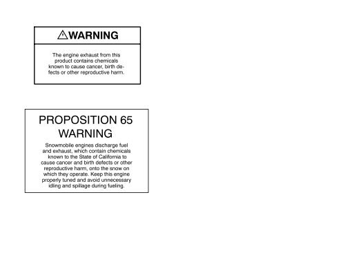
<strong>WARNING</strong><br />
The engine exhaust from this<br />
product contains chemicals<br />
known to cause cancer, birth defects<br />
or other reproductive harm.<br />
<strong>PROPOSITION</strong> <strong>65</strong><br />
<strong>WARNING</strong><br />
Snowmobile engines discharge fuel<br />
and exhaust, which contain chemicals<br />
known to the State of California to<br />
cause cancer and birth defects or other<br />
reproductive harm, onto the snow on<br />
which they operate. Keep this engine<br />
properly tuned and avoid unnecessary<br />
idling and spillage during fueling.
<strong>WARNING</strong><br />
¯ Adult Vehicle Only: This vehicle is designed for adult use only. The vehicle<br />
size, speed capabilities and control requirement prohibit operation by children.<br />
¯ Operating With A Passenger: (On approved models only) Operating a vehicle<br />
with a passenger reduces your ability to control the vehicle due to the added weight and<br />
change in weight distribution. Generally, reduce vehicle speeds and provide added space<br />
for maneuvering, since steering control may be reduced.<br />
¯ Excessive speeds: This vehicle is capable of high speeds. Exercise extreme<br />
caution when operating in unfamiliar terrain. Buried objects or uneven terrain can cause<br />
loss of control.<br />
¯ Body Protection: Always wear an approved helmet, eye protection and<br />
adequate clothing while operating this vehicle.<br />
¯ Alcohol Or Drugs: Never consume alcohol or drugs before or while operating<br />
this vehicle.<br />
¯ Night Riding and Limited Visibility: Limited visibility or excessive speeds may<br />
cause over-driving of headlights resulting in insufficient time to react to terrain changes or<br />
avoidance of unexpected obstacles.<br />
¯ Auxiliary Shut Off Switch: This switch is the primary means of stopping this<br />
vehicle in case of an emergency and is located on the top of the throttle control assembly.<br />
Depress the switch for proper function with the engine idling.<br />
¯ Safety Throttle System: This system is a supplementary safety device which<br />
stops the engine automatically in the event of a throttle system malfunction. See the<br />
Owner’s Manual for procedure to ensure proper system operation.<br />
¯ Vehicle Control: The Steering and braking ability are greatly reduced when<br />
operating on hardpacked snow, ice or when crossing roads. Reduced speed and extra<br />
care are required to maintain vehicle control.<br />
¯ Ski Skag Inspection: Inspect ski skags for wear every 500 miles or more often<br />
when operating on abrasive surface conditions. Replace ski skags when worn to 1/2 of<br />
original diameter.<br />
¯ Carbide Skags and Studs: These items enhance vehicle control on ice or<br />
hardpacked surfaces. Care must be taken to maintain a proper balance of ski carbides to<br />
track studs to maintain proper vehicle control. (See the Owner’s Manual for proper use of<br />
traction accessories.)<br />
¯ Cargo Rack: If this vehicle is equipped with a cargo rack, do not sit in or on the<br />
cargo rack. The combined cargo load and tongue weight on the hitch should not exceed<br />
75 lbs . (34 kgs.) Cargo load affects machine steering and braking response.<br />
¯ Rotating Track: Stay clear of the rotating track assembly. Entanglement may<br />
result.<br />
¯ Unfamiliar Rider: Never permit a guest to operate this vehicle unless the guest<br />
has read the Owner’s Manual and warnings.<br />
¯ Adjustment and Service: If you are not familiar with safe adjustment and service<br />
procedures, bring your vehicle to a qualified dealer for servicing or adjustment.<br />
¯ Read and understand warnings and the Owner’s Manual before operation.<br />
Severe injury or death can result from not heeding the warnings or understanding the<br />
Owner’s Manual.<br />
OIL INJECTION SYSTEM. UNMIXED FUEL ONLY. CHECK OIL LEVEL WHEN<br />
REFUELING.<br />
2000<br />
Universal<br />
Snow<br />
Owner’s Safety<br />
and Maintenance Manual<br />
Part No. 9915247 Rev 02<br />
PRINTED IN THE U.S.A.
FOREWORD<br />
Thank you for purchasing a <strong>Polaris</strong> snowmobile. We believe it is the standard of<br />
excellence for all snowmobiles manufactured in the world today. Many years of<br />
experience in engineering, design, and development have gone into making your<br />
<strong>Polaris</strong> snowmobile the finest machine we have ever produced.<br />
All machines, no matter how well engineered, require a certain amount of maintenance.<br />
Before using your snowmobile, take a few minutes to read through this<br />
manual and familiarize yourself with maintenance and operation procedures. It<br />
may be the most important time spent in knowing how to keep your machine running<br />
perfectly every day.<br />
If the registration form included with your snowmobile has not been completed<br />
by you and your dealer, be certain that it is; and make sure that it is<br />
forwarded to us. This completed form is necessary to insure warranty coverage.<br />
This manual also contains important pages devoted to safety and environment.<br />
Whether you are a long-time snowmobiler or a newcomer to this exciting winter<br />
sport, we urge you to seriously read this information.<br />
Remember, your snowmobile is capable of traveling at high speeds. This performance<br />
has been engineered into your <strong>Polaris</strong> to allow you the ultimate snowmobiling<br />
experience. Operators must be aware of risks involved when traveling at high<br />
speeds, on iced or hard packed surfaces, at night or in unfamiliar terrain. In addition,<br />
young or novice riders who do not have the ability or experience to physically<br />
control the machine in difficult situations should be instructed to reduce their speed<br />
until they become skilled riders.<br />
On machines designated for two passengers it is most important that the operator<br />
and rider communicate well and practice cornering techniques, rough terrain riding,<br />
etc., so that each is contributing to a safe, enjoyable ride. Keep the running<br />
board non-skid pads free of ice and snow and in good condition for increased safety<br />
and passenger comfort. The safe and courteous operation of your snowmobile<br />
- with respect for the environment - will insure you the continued enjoyment of the<br />
sport of snowmobiling.<br />
If you should experience any problems with your snowmobile, please return it to<br />
your dealer. He has received training which will enable him to perform any required<br />
repairs. Should any additional assistance be required, your dealer will work with<br />
our technical services department to resolve any problems.<br />
All of us at <strong>Polaris</strong> would like to extend to you our best wishes for plenty of fun-filled,<br />
safe snowmobiling pleasure with your new <strong>Polaris</strong>.<br />
All information in this manual is based upon the latest product data and specifications<br />
available at the time of printing. <strong>Polaris</strong> Industries Inc. reserves the right to<br />
make product changes and improvements which may affect illustrations or explanations.<br />
No part of this manual shall be reproduced or used without the written permission<br />
of <strong>Polaris</strong> Industries Inc.<br />
Illustrations included in this manual are general representations of parts having a<br />
similar function. Your model may differ.
The <strong>Polaris</strong> Preferred<br />
Registered Owners<br />
(PRO) Family<br />
Your Owners Program<br />
As the owner of a new <strong>Polaris</strong> vehicle, you are entitled to a FREE two- year membership<br />
in the <strong>Polaris</strong> PRO Family---the Preferred Registered Owners Family. It’s<br />
an owners program for <strong>Polaris</strong> owners like you, people who have chosen the finest<br />
recreational vehicle available, people who share an interest in <strong>Polaris</strong> and its products.<br />
Once your new vehicle’s warranty is registered, you will receive a PRO Family<br />
membership packet that will include:<br />
A letter of welcome to the PRO Family<br />
A PRO Family card with your name and membership number<br />
A colorful sticker of the PRO logo<br />
A PRO merchandise brochure and order form.<br />
As a PRO Family member, you’re entitled to opportunities such as:<br />
A free subscription to PRO Spirit, the official magazine of the PRO Family<br />
The chance to buy insurance for you <strong>Polaris</strong> vehicle. The toll-free insurance<br />
telephone number is: 1-800-473-0111<br />
The chance to arrange travel through the <strong>Polaris</strong> Travel Center. The toll-free<br />
travel telephone number is: 1-800-267-1915<br />
The chance to apply to serve on PRO Consumer Councils that provide input<br />
into the <strong>Polaris</strong> vehicles of the future<br />
The chance to serve as a PRO Field Evaluator and provide feedback on your<br />
new vehicle<br />
The chance to take part in national PRO snowmobile, ATV or personal watercraft<br />
rides<br />
The chance to purchase exclusive PRO Family merchandise<br />
And more!<br />
To order PRO merchandise, you’ll complete the order form you receive with your<br />
membership packet, take the form to your <strong>Polaris</strong> dealer and pay for the merchandise.<br />
The merchandise will be shipped directly to your home from the PRO merchandise<br />
fulfillment center.<br />
Watch for your PRO membership packet and the next issue of PRO Spirit magazine.<br />
This quarterly magazine will keep you informed about <strong>Polaris</strong> news and<br />
events, and special PRO merchandise, travel, and ride opportunities.<br />
Enjoy your new <strong>Polaris</strong> vehicle and welcome to the family--The <strong>Polaris</strong> PRO Family.
TABLE OF CONTENTS<br />
UNDERSTANDING <strong>WARNING</strong>S ................................ 1<br />
SAFETY <strong>WARNING</strong> AND OPERATION DECALS ............... 2-9<br />
OPERATION <strong>WARNING</strong>S ................................. 10-24<br />
PRESERVATION OF THE ENVIRONMENT ..................... 25<br />
IDENTIFICATION AND SPECIFICATIONS ................... 26-30<br />
OPERATION ............................................. 31-44<br />
BATTERY ................................................ 45-47<br />
MAINTENANCE ......................................... 48-105<br />
SUSPENSION ........................................ 106-134<br />
TROUBLESHOOTING ................................. 135-141<br />
ACCESSORIES ........................................... 142<br />
SERVICE AND WARRANTY ................................ 143<br />
WARRANTY .......................................... 144-147<br />
INDEX ............................................... 148-149
UNDERSTANDING <strong>WARNING</strong>S<br />
SAFETY ALERT<br />
The following precautionary signal words are used throughout this manual to convey<br />
the following messages:<br />
This is the safety alert symbol. When you see this<br />
symbol on your machine or in this manual, be alert<br />
to the potential for personal injury. Your safety is<br />
involved!<br />
<strong>WARNING</strong><br />
CAUTION<br />
Indicates a potential hazard<br />
which could result in<br />
serious injury or death.<br />
Indicates a potential hazard<br />
which may result in minor personal<br />
injury or damage to the<br />
snowmobile.<br />
NOTE<br />
The word “NOTE:” in this manual will<br />
alert you to key information or<br />
instructions.<br />
1
SAFETY <strong>WARNING</strong> AND OPERATION DECALS<br />
<strong>WARNING</strong><br />
Driving a snowmobile requires your<br />
full attention. Do not drink alcohol or<br />
use drugs or medications before or<br />
while driving as they will reduce your<br />
alertness and slow your reaction<br />
time. In most states and provinces it<br />
is prohibited by law to drive while intoxicated<br />
or under the influence of<br />
drugs.<br />
Be smart, be safe, don’t drink and<br />
drive!<br />
2
SAFETY <strong>WARNING</strong> AND OPERATION DECALS<br />
<strong>WARNING</strong><br />
<strong>Polaris</strong> Indys are high performance snowmobiles capable of traveling at very high<br />
speeds. Because of this, extra caution must be observed to ensure operator safety.<br />
Particular caution must be taken to make sure that the snowmobile is in excellent<br />
operating condition at all times. As with any performance snowmobile, we<br />
strongly recommend the operator check major and vital safety components each<br />
time before riding.<br />
All <strong>Polaris</strong> snowmobiles have been designed and tested to provide safe operation<br />
when used as directed. Failure of critical machine components may result from<br />
operation with any modification; especially those which increase speed or power.<br />
The machines may become aerodynamically unstable at speeds above those for<br />
which they are designed. There is also a significant possibility of loss of control at<br />
higher speeds.<br />
Due to our concern for the safety of our customers and the general public, <strong>Polaris</strong><br />
hereby strongly recommends and requests that consumers do not install on a <strong>Polaris</strong><br />
snowmobile any equipment which is intended to increase the speed or power<br />
of the machine, or make any other modifications to the machines for these purposes.<br />
Any modifications to the original equipment or the snowmobiles substantially<br />
increase the risk of bodily injury. Be aware that these modifications may<br />
create a substantial safety hazard.<br />
<strong>Polaris</strong> hereby informs you that the warranty on a snowmobile is terminated on the<br />
entire machine if any such equipment has been added to the machine or any modifications<br />
have been made to the machine which increase its speed or power.<br />
We also advise you to strictly follow the recommended maintenance program outlined<br />
on pages 48-100. This preventative maintenance program is designed to ensure<br />
that all critical components on the snowmobile are thoroughly inspected by<br />
your dealer at various mileage intervals.<br />
3
SAFETY <strong>WARNING</strong> AND OPERATION DECALS<br />
Your snowmobile is not a toy. It is a well-engineered and well constructed recreational<br />
vehicle. The following information is provided to aid you in its safe operation.<br />
NOTE: Warning decals have been placed on the vehicle for your protection. Read<br />
and follow the instructions on each decal carefully. In the eventany decalbecomes<br />
illegible or comes off, contact your <strong>Polaris</strong> dealer for a replacement. Any safety decal<br />
needing replacement will be provided by <strong>Polaris</strong> at no charge. The part number<br />
is printed on the decal.<br />
CAUTION: Although your <strong>Polaris</strong> has been designed to provide you with a safe,<br />
reliable snowmobile, much of its safety depends on the operator. Improper use of<br />
this snowmobile or failure to maintain it in good operating condition can result in<br />
injury. To reduce this possibility, read the following important safety information.<br />
4
SAFETY <strong>WARNING</strong> AND OPERATION DECALS<br />
(Text Below)<br />
<strong>WARNING</strong><br />
D Read and understand warnings and the Owner’s Manual before<br />
operation. Severe injury or death can result from not heeding the warnings.<br />
D Never consume alcohol or drugs before or while operating this vehicle.<br />
D Night riding, limited visibility, or excessive speeds may cause<br />
over-driving of headlights resulting in insufficient time to react to terrain<br />
changes or avoid unexpected obstacles.<br />
D This vehicle is capable of high speeds. Buried objects or uneven terrain<br />
can cause loss of control. Exercise extreme caution when operating in<br />
unfamiliar terrain.<br />
D This vehicle is designed for adult use only. The vehicle size, speed<br />
capabilities and control requirement prohibit operation by children.<br />
D Operating this vehicle with a passenger (On approved models only)<br />
reduces your ability to control the vehicle due to the added weight and<br />
change in weight distribution. Reduce vehicle speeds and allow added<br />
space for maneuvering, since steering control may be reduced.<br />
D Always wear an approved helmet, eye protection and adequate clothing<br />
while operating this vehicle.<br />
D The Auxiliary Shut Off Switch is the primary means of stopping this<br />
vehicle in case of an emergency and is located on the top of the throttle<br />
control assembly. Depress the switch to stop the engine and vehicle.<br />
Routinely check this switch for proper function with the engine idling.<br />
D The steering and braking ability are greatly reduced when operating on<br />
hard packed snow, ice or when crossing roads. Reduced speed and extra<br />
care are required to maintain vehicle control.<br />
D Carbide skags and studs enhance vehicle control on ice or hard-packed<br />
surfaces. Care must be taken to maintain a proper balance of ski carbides to<br />
track studs to maintain proper vehicle control. (See the Owner’s Manual for<br />
proper use of traction accessories.<br />
D Never permit a guest to operate this vehicle unless the guest has read<br />
the Owner’s Manual and warnings.<br />
5
SAFETY <strong>WARNING</strong> AND OPERATION DECALS<br />
(Text Below)<br />
6<br />
7075457<br />
BEFORE STARTING ENGINE: Check throttle and brake for proper operation.<br />
Check to see that hood is securely latched. Check surroundings to verify clear operation<br />
area. Determine that steering is free and functional.<br />
BRAKE LEVER LOCK: May relax when used for long periods. Do not leave brake<br />
engaged for more than five minutes.<br />
ALWAYS: Be seated and in position to control vehicle. Stop engine before attempting<br />
adjustments. Know the limitations of the vehicle and your skills as a driver. Understand<br />
your Owner’s Manual. Wear clothing designed for snowmobiling. Stops<br />
from high speed may cause fading or unexpected loss of braking ability.<br />
Oil injection system: Unmixed fuel only. Check oil level when refueling.<br />
If you do not have the Owner’s Manual for this vehicle, call 1-800-324-3764 to have<br />
one provided at no charge.
SAFETY <strong>WARNING</strong> AND OPERATION DECALS<br />
<strong>WARNING</strong><br />
AVERTISSEMENT<br />
Do not operate engine with hood open. N’opérez pas le moteur lorsque le capot est ouvert.<br />
Do not attempt adjustment with engine running. N’effectuez aucun ajustement lorsque le moteur est en marche.<br />
Do not operate engine with this guard open. Ne faites pas fonctionner le moteur lorsque ce garde de sécurité est ouvert.<br />
Never run engine with drive belt removed. Ne jamais laisser le moteur en marche lorsque la corroie d’entraînement est enlevée.<br />
Never service clutches yourself - see your dealer. Ne réparez jamais l’embrayage vous-mêmes, voir votre concessionnaire.<br />
Do not operate engine with hood open.<br />
Do not attempt adjustment with engine running.<br />
Do not operate engine with this guard open.<br />
Never run engine with drive belt removed.<br />
Never service clutches yourself - see your dealer.<br />
STAY CLEAR OF TRACK. DO NOT SIT ON SEAT BACK. ENTANGLEMENT WITH THE<br />
TRACK OR A FALL FROM SEAT BACK CAN RESULT IN SEVERE INJURY OR DEATH.<br />
<strong>WARNING</strong><br />
AVERTISSEMENT<br />
1. Stay clear of track. • Ne pas s’approcher de la chenille<br />
2. Do not sit on seat back or cargo area. • Ne pas s’assoir sur le siège à l’arrière du<br />
compartiment à bagages.<br />
3. Combined cargo and tongue weight should not exceed 40 lbs. (18 kg). Cargo load affects<br />
machine steering response. • Le poids combiné des bagages et de la barre d’attelage ne<br />
doit pas dépasser 18 kg (40 livres). Le poids des bagages affecte la réponse de la direction<br />
de la machine.<br />
7073290<br />
1. Stay clear of track.<br />
2. Do not sit on seat back or cargo area.<br />
3. Combined cargo and tongue weight should not exceed 40 lbs. (18 kg). Cargo<br />
load affects machine steering response.<br />
7
SAFETY <strong>WARNING</strong> AND OPERATION DECALS<br />
Models Equipped With Reverse Only<br />
(Text Below)<br />
NOTE: Illustration of shift pattern may vary. Your model may differ.<br />
VEHICLE CAPABLE OF EXCESSIVE REVERSE SPEED!<br />
Reverse operation can be dangerous even at low speeds. Steering control<br />
becomes difficult in reverse. Misuse of reverse can result in injury. Avoid<br />
turning at sharp angles in reverse.<br />
Transmission may not always be in the gear indicated by the shift lever. Always<br />
apply throttle slowly.<br />
On machines with reverse it is especially important to maintain track tension<br />
as specified in the owner’s manual. If specified track tension is not maintained<br />
severe damage to the machine may occur, which can result in loss of<br />
vehicle control. Loss of vehicle control can result in severe personal injury or<br />
death.<br />
For More Info: See Operator’s Safety and Maintenance Manual supplied<br />
with reverse kit.<br />
SHIFT PATTERN<br />
Make sure lever is shifted completely to forward or reverse position. Do not<br />
force into reverse. If not able to shift to reverse, apply throttle gently to move<br />
vehicle. CAUTION: Do not attempt to shift until machine has come to a<br />
complete stop or chaincase damage may occur.<br />
8
SAFETY <strong>WARNING</strong> AND OPERATION DECALS<br />
Some Liquid Cooled Models<br />
CAUTION<br />
ATTENTION<br />
Release pressure before removing cap. Cooling fluid must be<br />
up to the base of the pressure cap in hot or cold conditions.<br />
Refer to the Owner’s Manual for fluid level in overflow bottle.<br />
Do not operate above 40 mph with<br />
hood to air box foam removed or<br />
engine failure will result.<br />
DO NOT OPERATE WITH INTAKE SILENCER<br />
REMOVED.<br />
NE PAS OPERER LORSQUE LE SILENCIEUX<br />
DE LA PRISE D’AIR EST ENLEVE.<br />
9
OPERATION <strong>WARNING</strong>S<br />
Before Starting The Engine<br />
Read and Understand Your Owner’s Manual<br />
Read the Owner’s Manual completely now, and re-read it occasionally. We have<br />
attempted to provide you with as much information as possible to alert you to the<br />
safety requirements of snowmobiling.<br />
Check Throttle and Brake for Proper Operation<br />
The throttle and brake are the primary controls of your snowmobile. If either should<br />
malfunction, a serious loss of control could result.<br />
When checking the throttle, make sure the control lever will compress evenly and<br />
smoothly. When the lever is released, it should immediately return to the idle position<br />
without binding or hesitation. If the throttle does not function smoothly, do not<br />
attempt to start the engine. Have the throttle serviced before starting the engine.<br />
The need for a properly functioning brake is vital. This snowmobile is equipped<br />
with the highest quality brake system available. The brake must be checked for<br />
correct operation before starting the engine. See page 13 for details.<br />
Check for Proper Operation of Steering System<br />
Check for proper operation of the steering system by manually turning the skis<br />
completely to the right and to the left. If difficulty is encountered, check for ice and<br />
snow buildup which may be obstructing the steering linkage. Make certain all<br />
greasable components are properly lubricated.<br />
Single Rider Snowmobiles<br />
Some <strong>Polaris</strong> snowmobile<br />
models are designed<br />
for a single occupant<br />
only. A decal on<br />
the console of these<br />
models indicates single<br />
occupant operation.<br />
<strong>WARNING</strong>/AVERTISSEMENT<br />
This vehicle is designed for operator only.<br />
“NO PASSENGER”<br />
Ce vehicule est concu pour ne transporter<br />
que le conducteur.<br />
“AUCUN PASSAGER”<br />
OR<br />
<strong>WARNING</strong>/AVERTISSEMENT<br />
10
OPERATION <strong>WARNING</strong>S<br />
Driving 2-Up<br />
When operating a 2-Up machine with a passenger, the driver should be aware that<br />
more space will be required to make turns, and a longer distance will be necessary<br />
for stopping. Lower speeds should be observed whenever riding 2-Up.<br />
CAUTION: Always make certain the passenger remains seated behind the driver,<br />
facing forward, with both feet placed firmly on the running boards. Reduce operating<br />
speed and be particularly careful to avoid “jumping” your snowmobile.<br />
Some <strong>Polaris</strong> snowmobile models are designed for two occupants. A decal on the<br />
hood of these models indicates that the vehicle is designed for one operator and<br />
one passenger only. Machines designated as double occupant should never be<br />
operated with more than two people on board. When traveling with a passenger<br />
aboard, it is the driver’s responsibility to operate the machine in a safe manner.<br />
Remember that control becomes more difficult with two people on board. Reduce<br />
speeds to retain control!<br />
<strong>WARNING</strong><br />
Use of a backrest can hinder<br />
operator weight shifting.<br />
This may affect control<br />
of this rider-active<br />
vehicle in certain extreme<br />
driving situations.<br />
Track<br />
Inspection<br />
<strong>WARNING</strong>/AVERTISSEMENT<br />
This vehicle is designed for operator and<br />
“ONE” passenger only.<br />
Ce vehicule est concu pour ne transporter<br />
que le conducteur et “UN SEUL” passager.<br />
<strong>WARNING</strong>/AVERTISSEMENT<br />
Driving at wide-open<br />
throttle for extended periods<br />
of time in marginal lubrication<br />
could severely<br />
damage track rods, break<br />
track edges, and cause<br />
other track damage. Examples<br />
of marginal lubrication would include lakes without snow cover, icy trails<br />
and no-snow conditions.<br />
Always inspect for damage before using the vehicle. Use of traction products such<br />
as studs, ice growsers, paddles, etc. will increase the possibility of track damage<br />
and/or failure. Operating the snowmobile with a damaged track will increase the<br />
possibility of track damage and/or failure, which could cause loss of control<br />
resulting in severe injury or death.<br />
NOTE: Track damage or failure caused by operation on ice or poor lubrication<br />
conditions will void the track warranty.<br />
Do Not Operate Engine With Intake Silencer or Filter Removed<br />
When operating engine with intake silenceror filterremoved, damage to the engine<br />
may occur.<br />
11<br />
or
OPERATION <strong>WARNING</strong>S<br />
Stay Clear of Track<br />
During warm-up and operation, stand clear of the rotating track. Do not use too<br />
much throttle during warm-up or when track is free hanging. Entanglement and<br />
serious injury or death may result.<br />
Do Not Operate Engine With Clutch Guard Removed<br />
The clutch guard is designed to protect the operator from metal parts in the event<br />
the clutch should fail. Although the chance of failure is extremely remote, do not<br />
defeat the purpose of the guard by removing it. It is provided for your safety.<br />
Never Run Engine With Drive Belt Removed<br />
Operation of the engine with the belt removed can result in serious over-speed<br />
condition. Any servicing which requires operation without a belt must be done by<br />
your dealer.<br />
Never Service Clutches Yourself - See Your Dealer<br />
The clutch is a complex mechanism which operates at high rotational speeds.<br />
Each clutch is dynamically balanced before installation. Any tampering by the<br />
owner may disrupt this precision balancing and create an unstable condition.<br />
Seat Back/Cargo Carrier<br />
Do not sit on seat back or cargo area. Do not exceed carrier and rack weight limits.<br />
Cargo load affects machine steering response.<br />
Disabled Operators<br />
Safe operation of this rider-active vehicle requires good judgement and physical<br />
skills. Persons with cognitive or physical disabilities who operate this vehicle have<br />
an increased risk of overturns and loss of control which could resultin serious injury<br />
or death.<br />
12
Hydraulic Brakes<br />
OPERATION <strong>WARNING</strong>S<br />
The need for a properly functioning brake is vital. <strong>Polaris</strong> snowmobiles are<br />
equipped with the highest quality hydraulic disc brake system available. The following<br />
items must be checked each time before starting the engine to assure proper<br />
operation.<br />
Brake Lever Travel<br />
When the brake handle is depressed<br />
(A) , it should move no<br />
closer than 1/2″ (1.3 cm) from the<br />
handgrip. Excessive travel indicates<br />
low fluid level or airin the hydraulic<br />
system. If the lever travel<br />
is excessive, refer to the brake<br />
bleeding information on page 69.<br />
A<br />
Lever Feel<br />
A hydraulic system multiplies the force of your hand squeeze on the brake lever.<br />
Proper operation depends upon an adequate air and moisture-free supply of hydraulic<br />
brake fluid in the system. If the brake lever feels “spongy” when squeezed,<br />
the level and condition of the fluid must be checked; as well as checking for the<br />
presence of air in the fluid system. Refer to page 69 for more information orcontact<br />
your dealer for service. Replace brake fluid at least every two years with <strong>Polaris</strong><br />
DOT 3 high temperature brake fluid. All DOT 3 brake fluid is not alike. We recommend<br />
the use of <strong>Polaris</strong> brake fluid (PN 2870990).<br />
<strong>WARNING</strong><br />
Continued abusive brake application with a “spongy” brake condition may cause<br />
a complete loss of brakes; which could result in severe injury or death.<br />
Mechanical Brakes<br />
Brake Lever Travel<br />
Measure the clearance between the<br />
lever and brake block. Inspection<br />
should be made with the lever firmly<br />
depressed. Distance B should be no<br />
more than 3/4″ (1.9 cm).<br />
Excessive travel indicates a need to<br />
adjust the brake cable adjuster. Refer<br />
to the mechanical brake adjustment<br />
information on page 72.<br />
B<br />
13
OPERATION <strong>WARNING</strong>S<br />
Park Brake Lever Lock<br />
1. Brake Handle<br />
2. Park Brake Lever Lock<br />
(Not all models are<br />
equipped with a park<br />
brake)<br />
3. Master Cylinder<br />
Reservoir<br />
4. Master Cylinder Cover<br />
5. Fluid Level Indicator<br />
1<br />
3<br />
2 4<br />
5<br />
Your snowmobile has a brake<br />
brake lever lock. It is located<br />
over the brake lever. Use the<br />
brake lever lock only when you<br />
want the machine to remain<br />
stationary (e.g. when parked<br />
on an incline) for a period of<br />
five minutes or less. To apply<br />
lock, squeeze brake handle<br />
and push forward on brake lever lock. Hold lock forward and release brake handle.<br />
To release lock, squeeze brake handle until lever returns to the unlock position.<br />
The park brake light on the console will be lit when the park brake lever lock is set<br />
and the engine is running. It is also lit when the service brake is in use. If the park<br />
brake light does not come on when park brake or service brake is in use, have it<br />
serviced by your dealer.<br />
<strong>WARNING</strong><br />
If the park brake lever lock is left partially or entirely engaged while riding the snowmobile,<br />
it could cause overheating of the brakes which could result in damage to<br />
the brake caliper. In extreme cases it could cause a fire which could result in serious<br />
injury or death.<br />
Check to See That the Hood is Securely Latched<br />
The hood of the snowmobile protects the operator from moving parts as well as aiding<br />
in sound emission control and various other functions. Under no circumstances<br />
should your snowmobile be operated with the hood open or removed.<br />
14
Auxiliary Shut-Off Switch<br />
OPERATION <strong>WARNING</strong>S<br />
Check auxiliary shut-off switch for proper operation. Push down to stop engine.<br />
Pull up to release and start engine.<br />
Tether Switch (accessory on all models)<br />
Check tether switch for proper operation.<br />
Remove Ignition Key<br />
Don’t tempt anyone to steal or ride your snowmobile without permission by leaving<br />
the key in the ignition.<br />
Lighting Check<br />
Check headlight high and low beam, taillight and brake light for normal operation.<br />
Check Surroundings to Verify Clear Operating Area<br />
It is most important to assure yourself that you have a clear area all around your<br />
snowmobile, including an area clear of bystanders. Remember that the possibility<br />
always exists of some sideways vehicle movement, or a little more throttle than intended;<br />
or debris may be thrown by the track. If you are assured of a clear area<br />
surrounding you before you start, you can devote your full attention to operating<br />
the snowmobile.<br />
Be Seated and in Position to Control the Vehicle<br />
Improper operator position on the snowmobile can be the source of serious injury.<br />
Remember that operating a snowmobile does require skill and balance for proper<br />
control, and an improper position can seriously reduce your ability to control your<br />
snowmobile. The style of positioning will vary from person to person as they become<br />
more skilled; but under most conditions the proper position is to be seated,<br />
feet on the running boards, and in a comfortable position for proper throttle, brake,<br />
and steering control.<br />
<strong>WARNING</strong><br />
Your snowmobile is propelled<br />
by a revolving track<br />
which must be partially exposed<br />
for proper operation.<br />
Serious injuries may be<br />
caused by operator carelessness<br />
resulting in hands,<br />
feet, or clothing becoming<br />
entangled in the track. Be<br />
alert. Remember, being<br />
properly seated keeps you<br />
clear of the track.<br />
Never hold the snowmobile up or stand behind it while warming up the track. A<br />
loose track or flying debris could cause serious personal injury or death.<br />
15
OPERATION <strong>WARNING</strong>S<br />
Stop Engine Before Attempting Adjustments<br />
<strong>WARNING</strong><br />
The snowmobile engine compartment contains moving parts. Shields and guards<br />
have been provided for your safety, but it is still possible to carelessly get your<br />
hands or fingers into a moving belt or a rotating shaft. For this reason neverattempt<br />
adjustments with the engine running. Serious personal injuries can result. The<br />
proper method is to turn off the ignition, raise the hood, make the adjustment, secure<br />
shields and guards, secure the hood, and then re-start the engine to check<br />
its operation. The same is true of track alignment. If the track must be re-aligned,<br />
it is recommended that this service be performed by your dealer.<br />
Always Wear Clothing Designed for Snowmobiling<br />
Clothing designed for snowmobiling is warm, comfortable and safe.<br />
<strong>WARNING</strong><br />
Always wear an approved helmet<br />
and eye protection. Don’t wear<br />
loose clothing or long scarves because<br />
they can easily become entangled<br />
in moving parts. Also, be<br />
aware of the weather forecast and<br />
especially the wind chill. A table is<br />
provided on page 19 for your reference.<br />
Be prepared. Be warm and<br />
comfortable.<br />
Know the Limitations of the Machine and Your Skills as a<br />
Driver<br />
D Observe state and local laws governing snowmobile operation. They have<br />
been established for your protection.<br />
D<br />
D<br />
Traveling at night requires extra caution. Check both headlight and taillight to<br />
ensure proper operation. Do not “over-drive” your headlight beam. A good rule<br />
to follow is to be able to bring your machine to a stop in the distance illuminated<br />
by the headlight. High speed driving at night is dangerous and unwise, and<br />
could result in severe personal injury or death.<br />
Be courteous to oncoming traffic by dimming your headlights and lowering your<br />
vehicle speed. Your snowmobile is equipped with a high output head lamp system<br />
that can cause discomfort to operators of oncoming vehicles if the headlight<br />
is not dimmed.<br />
16
OPERATION <strong>WARNING</strong>S<br />
D<br />
Wire fences are a serious<br />
hazard. Unless you are thoroughly<br />
familiar with an area,<br />
you should always be on the<br />
alert for fences. Single<br />
strands are especially dangerous,<br />
since there can be a<br />
great distance between<br />
posts. Guy wires on utility<br />
poles are also difficult to distinguish.<br />
Reduce speed<br />
when traveling near poles,<br />
posts, or other obstacles. Be<br />
especially alert if you are<br />
snowmobiling after dark.<br />
D<br />
When travelling on lakes and<br />
streams that are strange to<br />
you, always check with local<br />
residents or authorities for<br />
general information on conditions.<br />
Thin ice, open water,<br />
and snowmobiles are not<br />
compatible. Before riding<br />
your machine on a frozen<br />
body of water, be sure that the<br />
ice is thick enough to support<br />
the machine and its operator<br />
as well as the force created by<br />
a moving vehicle. Variances<br />
in snow depth and/or water<br />
currents can result in uneven<br />
ice thickness. Use common<br />
sense and good judgment at<br />
all times as drowning may result<br />
if you and the snowmobile<br />
break through the ice.<br />
Snow<br />
Ice<br />
17
OPERATION <strong>WARNING</strong>S<br />
D<br />
Remember, the sound of your machine<br />
will drown out the sound of<br />
approaching vehicles. Look ahead,<br />
behind, and to the sides before turning<br />
or crossing railroad crossings or<br />
highways. Steep embankments<br />
may also hide your view. Always<br />
leave yourself a way out. Make<br />
sure the way is clear before you<br />
cross railroads and other roads and<br />
highways.<br />
D<br />
Drive defensively when traveling in a group of snowmobiles to avoid accidents.<br />
Don’t tailgate. Allow ample stopping distances.<br />
D<br />
Always be alert and pay attention to the trail ahead of you. Multiplying speed<br />
(MPH) by 1.5 will equal the approximate number of feet per second your machine<br />
travels. If your speed is 40 MPH, your machine is travelling approximately<br />
60 feet per second. This means that if you look back for only two seconds, your<br />
machine will travel about 120 feet. If your speed is 60 MPH, your machine will<br />
travel approximately 180 feet in two seconds.<br />
D<br />
When teaching inexperienced operators to ride, set up a nearby predetermined<br />
course. Make sure they know how to drive and control the snowmobile before<br />
you allow them to make longer distance runs. Teach them proper snowmobile<br />
courtesy. Enroll them in a driver’s training and safety course sponsored by a<br />
local or state organization.<br />
18
Windchill/Temperature Charts<br />
OPERATION <strong>WARNING</strong>S<br />
The following information is provided as a guide to determine what temperatures<br />
are dangerous when riding your snowmobile.<br />
WIND CHILL CHART (°F)<br />
Estimated<br />
Actual Thermometer Reading (°F)<br />
Wind Speed in<br />
MPH 50 40 30 20 10 0 -10 -20 -30 -40 -50 -60<br />
Equivalent Temperature (°F)<br />
Calm 50 40 30 20 10 0 -10 -20 -30 -40 -50 -60<br />
5 48 37 27 16 6 -5 -15 -26 -36 -47 -- 57 -68<br />
10 40 28 16 4 -9 -21 -33 -46 -58 -70 -83 -95<br />
15 36 22 9 -5 -18 -36 -45 -58 -72 -85 -99 -112<br />
20 32 18 4 -10 -25 -39 -53 -67 -82 -96 -110 -124<br />
25 30 16 0 -15 -29 -44 -59 -74 -88 -104 -118 -133<br />
30 28 13 -2 -18 -33 -48 -63 -79 -94 -109 -125 -140<br />
35 27 11 -4 -20 -35 -49 -67 -82 -98 -113 -129 -145<br />
40 26 10 -6 -21 -37 -53 -69 -85 -100 -116 -132 -148<br />
Wind Speeds<br />
Greater Than<br />
40 MPH Have<br />
Little Added<br />
Effect<br />
Little Danger<br />
(For Properly<br />
Clothed Person)<br />
Increasing<br />
Danger<br />
Great<br />
Danger<br />
Danger From Freezing of Exposed Flesh<br />
WIND CHILL CHART (°C)<br />
Estimated<br />
Actual Thermometer Reading (°C)<br />
Wind Speed in<br />
KPH 5 0 -5 -10 -15 -20 -25 -30 -35 -40<br />
Equivalent Temperature (°C)<br />
0 5 0 -5 -10 -15 -20 -25 -30 -35 -40<br />
10 1 -4 -11 -16 -22 -27 -33 -38 -45 -50<br />
20 -4 -9 -17 -23 -29 -36 -42 -48 -54 -61<br />
30 -7 -13 -21 -28 -35 -42 -48 -55 -63 -69<br />
40 -9 -16 -24 -32 -39 -47 -53 -61 -69 -76<br />
50 -11 -18 -26 -34 -41 -49 -57 -64 -73 -80<br />
60 -12 -19 -27 -35 -43 -51 -59 -66 -75 -82<br />
70 -13 -20 -28 -36 -44 -52 -60 -68 -76 -84<br />
Wind Speeds<br />
Greater Than<br />
70 KPH Have<br />
Little Added<br />
Effect<br />
Little Danger<br />
(For Properly<br />
Clothed Person)<br />
Increasing<br />
Danger<br />
Great<br />
Danger<br />
Danger From Freezing of Exposed Flesh<br />
19
OPERATION <strong>WARNING</strong>S<br />
Cold Weather Driveaway<br />
Whenever the machine has been parked for some length of time, especially overnight,<br />
always shake loose the skis and track before attempting to put the machine<br />
into motion. The throttle should always be opened with enough authority to put the<br />
machine into motion, staying within safety limits and with respect to a passenger,<br />
on a two passenger machine.<br />
Powder Snow Operation<br />
Your <strong>Polaris</strong> is designed to operate best on snow. Maneuverability is attained by<br />
the steering, skis, and the shifting of your body weight. Maximum control will be<br />
attained by shifting body weight. Maneuverability will change for lighter operators<br />
or machines carrying a load or a passenger where allowed.<br />
CAUTION: Do not operate for prolonged periods on blacktop,<br />
gravel, or glare ice.<br />
It is essential that your machine be operated under conditions with adequate snow<br />
cover, as snow provides the only lubrication for the power slide suspension and,<br />
on liquid cooled models, cooling for the engine. Failure to do so will result in excessive<br />
wear and damage to the slide rail and track and/or engine.<br />
If the machine becomes stuck in snow, free the running board area, and step down<br />
the snow in front of the machine so that when the throttle is opened the machine<br />
will be able to climb up and over. The operator can then mount the machine and<br />
continue.<br />
<strong>WARNING</strong>: Snow and ice buildup in the underhood area can<br />
cause interference with the steering function.<br />
Before driving, be sure that ice and snow are not interfering with full left and right<br />
steering by manually turning the skis to the left and right. If difficulty is encountered,<br />
check for ice and snow buildup which may be obstructing the steering linkage.<br />
Snow screen and bib kits are available through your dealer to help reduce snow<br />
and ice buildup.<br />
NOTE: The ability of the machine to travel in adverse conditions will improve as<br />
the operator gains experience.<br />
20
OPERATION <strong>WARNING</strong>S<br />
Hard Packed Snow<br />
<strong>WARNING</strong><br />
Steering and braking control are substantially reduced under<br />
packed snow or icy conditions.<br />
Excessive shifting of operator body weight when turning on hard packed snow or<br />
slippery surfaces can result in loss of vehicle control and serious injury. Reduce<br />
speed as required to maintain control under these conditions.<br />
Ice<br />
It is dangerous to operate on ice or under slippery conditions. If ice or slippery<br />
conditions are unavoidable, use extreme caution and operate at<br />
speeds no faster than a walk. Never attempt an abrupt change of direction on a<br />
slippery surface. The chance of “spin-out” increases under these conditions.<br />
Before riding your snowmobile on a frozen body of water, be sure that the ice is<br />
thick enough to support the machine and its occupant(s) as well as the force that<br />
is created by a moving vehicle. Severe injury or death can result if the snowmobile<br />
and/or its occupant(s) break through the ice.<br />
21
OPERATION <strong>WARNING</strong>S<br />
Hilly Terrain<br />
Exercise caution and good judgement when travelling in hilly terrain.<br />
Crossing a Slope (Sidehilling)<br />
<strong>WARNING</strong><br />
Sidehilling can be very dangerous and is not recommended for inexperienced<br />
snowmobilers.<br />
Crossing the face of a slope (sidehilling) requires the operator to position his/her<br />
weight in order to maintain proper balance. Kneel with the knee of the downhill leg<br />
on the seat and the foot of the uphill leg on the running board. This position makes<br />
it easier to shift your weight as needed. As you travel across the slope, lean uphill<br />
to position your weight on the uphill side.<br />
22
Riding Uphill<br />
OPERATION <strong>WARNING</strong>S<br />
Hill climbing may be accomplished by using one of two methods, depending upon<br />
the steepness of the hill.<br />
Sidehilling may be used if there are few obstacles on the hill. The operator should<br />
assume a kneeling position (as in Sidehilling), keeping body weight on the uphill<br />
side at all times. Maintaining a steady, safe speed, approach the hill at an angle,<br />
continuing as far as possible in this direction; then switch to the opposite angle and<br />
riding position.<br />
The direct climb method requires extreme caution. The operator should assume<br />
a standing position with body weight kept low and forward, accelerating before the<br />
start of the climb and then releasing throttle pressure enough to prevent track slippage.<br />
In either type of climb, the operator must slow down when reaching the crest of the<br />
hill. Be prepared to react to obstacles, sharp drops, or other people or vehicles<br />
which may be on the other side of the hill.<br />
If you are unable to continue up a hill, turn the machine downhill before it<br />
loses momentum. If this is not possible, spin the track just enough to dig<br />
in so the machine won’t roll back down the hill. Stop the engine and set the parking<br />
brake (if equipped). Keeping away from the downhill side of the machine, pull the<br />
rear of the snowmobile around, pointing the machine back downhill. Once the<br />
snowmobile is pointed downhill, mount the machine, restart the engine, release the<br />
parking brake, and descend the hill.<br />
Riding Downhill<br />
When riding downhill, keep speed at a minimum. It is important to apply just<br />
enough throttle to keep the clutch engaged while descending the hill. This willallow<br />
use of the engine’s compression to help slow the machine, and keep the snowmobile<br />
from rolling freely downhill.<br />
<strong>WARNING</strong><br />
Use extreme caution when applying the brake during a descent. Excessive braking<br />
will cause the track to lock, resulting in loss of control.<br />
23
OPERATION <strong>WARNING</strong>S<br />
Responsible Driving<br />
If you operate the snowmobile improperly, you will cause situations which will exceed<br />
your driving skills. Each snowmobile handles differently, and even if you are<br />
a seasoned driver, it is strongly recommended that you spend some time getting<br />
the feel for this particular machine before attempting ambitious maneuvers. If you<br />
are new to snowmobiling, take enough time to acquaint yourself with the machine<br />
and what it will and won’t do under various conditions.<br />
Acquire a feel for your machine before attempting ambitious maneuvers.<br />
The snowmobile depends on your body position for proper balance in<br />
executing turns, traversing hills, etc. It’s best to start on a smooth level area to begin<br />
building your operating experience.<br />
Before you let someone else use your snowmobile, be sure you know the<br />
extent of their operating skills. Check to see if they have taken a snowmobile<br />
safety course and have an operator’s certificate. For their protection, as well<br />
as yours, make sure they take a snowmobile safety course. Everyone can benefit<br />
from the course.<br />
Don’t “jump” your snowmobile. Jumping can injure your back because of<br />
spinal compression. The seat and suspension of your snowmobile have<br />
been designed and constructed to give you protection, but they do have limits.<br />
Your snowmobile is not intended for this kind of use.<br />
24
PRESERVATION OF THE ENVIRONMENT<br />
We recommend that you drive your snowmobile with consideration for the protection<br />
and preservation of our environment.<br />
Noise Level<br />
Probably the most publicized subject with regard to snowmobiles is noise. The Society<br />
of Automotive Engineers (SAE), which is the standard-setting body for snowmobiles,<br />
has recommended that snowmobiles conform to prescribed sound levels.<br />
Your <strong>Polaris</strong> snowmobile has been engineered to conform to these SAE standards.<br />
In order to be meaningful, all regulations require the cooperation of the snowmobile<br />
driver. Muffling systems, designed to reduce noise levels, should not be altered<br />
or removed. Snowmobile drivers must be aware that they have a public responsibility<br />
to operate their snowmobiles with concern for others. As a snowmobile operator<br />
you may not realize the sound of your snowmobile may annoy non-snowmobilers.<br />
We are attempting to do our part through the manufacture of quieter<br />
machines, and we also ask your help in the effort to further reduce the impact of<br />
noise.<br />
Air Pollution<br />
As a part of <strong>Polaris</strong>’ plan for the snowmobile’s compatibility within the environment,<br />
our engineers are investigating ways to reduce emission levels of two-stroke engines.<br />
We expect our efforts to lead to the reduction of potential air pollution.<br />
In addition to technological research, we also suggest that governmental agencies,<br />
manufacturers, distributors, dealers, ecologists, and other interested parties<br />
work together to develop data on environmental topics. We will continue to participate<br />
in this type of study so that someday we may find the answers to these difficult<br />
issues.<br />
Environmental Protection<br />
As part of the continuing environmental education campaign, we are encouraging<br />
state and provincial governments across the snowbelt to adopt rigorous safety<br />
training programs which also encourage protection of ourenvironment, wildlife and<br />
vegetation. Snowmobile clubs and other organizations are working together to<br />
protect our environment. It is very important that we encourage them as well as<br />
become actively involved ourselves.<br />
Respect your snowmobile;<br />
respect your environment;<br />
and you will earn<br />
the respect of everyone.<br />
25
IDENTIFICATION AND SPECIFICATIONS<br />
Vehicle Nomenclature<br />
Refer to illustrations on following pages. NOTE: Illustrations are a general representation.<br />
Your model may differ.<br />
1. Hood 13. Suspension<br />
2. Headlight 14. Nosepan<br />
3. Windshield 15. Trailing Arm<br />
4. Handlebar 16. Skis<br />
5. Seat 17. Front Bumper<br />
6. Storage/Rear 18. Console<br />
7. Taillights 19. Vehicle I.D. Number (Right Side)<br />
8. Backrest 20. Rear Bumper<br />
9. Tunnel Extension 21. Passenger Hand Hold<br />
10. Passenger Hand Hold Strap 22. Lifting Hand Hold<br />
11. Track 23. Snow Flap<br />
24. Mountain Bar<br />
Vehicle Nomenclature, Cont.<br />
3<br />
17<br />
1<br />
2<br />
4<br />
5<br />
10<br />
8<br />
22<br />
6<br />
7<br />
20<br />
16<br />
14<br />
15<br />
19<br />
13<br />
11<br />
9<br />
23<br />
26
Vehicle Nomenclature, Cont.<br />
IDENTIFICATION AND SPECIFICATIONS<br />
18<br />
2<br />
3<br />
4<br />
17<br />
22<br />
1<br />
5<br />
6<br />
8<br />
20<br />
16<br />
14<br />
15<br />
19<br />
13<br />
11<br />
23<br />
3<br />
18<br />
17<br />
1<br />
2<br />
4<br />
5<br />
10<br />
8<br />
22<br />
6<br />
7<br />
9<br />
16<br />
14<br />
15<br />
19<br />
13<br />
11 23<br />
27
IDENTIFICATION AND SPECIFICATIONS<br />
Vehicle Nomenclature, Cont.<br />
3<br />
24<br />
4 5<br />
1<br />
2<br />
6<br />
7<br />
17<br />
20<br />
23<br />
16<br />
14 15<br />
19<br />
13<br />
11<br />
28
Controls and Instruments<br />
IDENTIFICATION AND SPECIFICATIONS<br />
General Representations<br />
Your Model May Differ<br />
1. Headlight Dimmer Switch (2<br />
Position)<br />
2. Fuel Filler Cap/Gas Gauge<br />
3. Auxiliary Shut-Off Switch<br />
(Push/Pull). Operation found<br />
on page 40.<br />
4. Throttle Control<br />
5. Recoil Starter Handle<br />
6. Choke Control<br />
7. Ignition Switch<br />
8. Tachometer (may include indicator<br />
/ warning lights)<br />
9. Speedometer (may include indicator<br />
/ warning lights)<br />
10. Brake Lever<br />
11. Low Oil Warning,Brake Light,<br />
High Beam, Temp, premium fuel<br />
options<br />
12. Accessory Indicators<br />
13. Safety Decals<br />
14. Hood Hold Down<br />
15. Handlebar Grip Warmer Switch<br />
16. Thumbwarmer Switch<br />
17. Thumbwarmer/Handwarmer<br />
Switch<br />
18. Reverse Lever<br />
19. Fuel Gauge<br />
20. Temperature Light<br />
21. Tether Switch<br />
22. Power Plug<br />
23. Electric Shock Absorber Gauge<br />
1<br />
10<br />
6<br />
10<br />
15<br />
17<br />
1<br />
10<br />
16<br />
1<br />
9<br />
9<br />
20<br />
19<br />
9<br />
12<br />
11<br />
2<br />
2 7<br />
20<br />
7<br />
16 15<br />
6<br />
8<br />
8<br />
13<br />
4<br />
3<br />
13<br />
3<br />
4<br />
23<br />
14<br />
13<br />
2<br />
7 21 6 22 18<br />
3<br />
4<br />
5<br />
29
IDENTIFICATION AND SPECIFICATIONS<br />
Backrest<br />
1. Backrest Cushion Adjuster<br />
2. Backrest Adjuster Cable<br />
3. Grab Bar Adjustment Knob<br />
4. Passenger Handwarmer Switch<br />
5. Wind Deflector<br />
6. Backrest Adjustment Lever<br />
7. Passenger Hand Hold<br />
5<br />
7<br />
1<br />
2<br />
4<br />
6<br />
3<br />
30
OPERATION<br />
Carburetion<br />
Proper carburetor adjustment is critical, since a mixture too lean (too much air, too<br />
little fuel) will result in overheating of the combustion chamber causing pre-ignition<br />
of the fuel. This results in piston burning, bearing failure, or complete engine failure.<br />
A lean mixture can be the result of fuel line restrictions, foreign matter in the<br />
carburetor, clogged fuel filter, etc.<br />
A mixture too rich (too much fuel, too little air) is also unfavorable because it can<br />
foul plugs and cause generally poor engine performance.<br />
All carburetors have been pre-set at the factory for adequate fuel supply. Higher<br />
altitude operation may require different adjustment and settings.<br />
RMK models are pre-set to operate at altitudes of 6000-9000 feet above sea level.<br />
<strong>WARNING</strong><br />
Carburetor adjustments must be performed by your dealer, since mistakes can result<br />
in possible operator safety hazards as well as serious engine damage.<br />
Remember, correct setup provides engine RPM within its given power band at full<br />
throttle settings and also provides maximum efficiency and operation at all other<br />
throttle openings. Your dealer has the training and tools required to perform any<br />
adjustments for you.<br />
<strong>WARNING</strong><br />
Engine damage may result if jetting or clutching is wrong. Never service clutches<br />
yourself. See your dealer.<br />
Drive System<br />
1. Engine<br />
2. Torque Converter<br />
(Drive Clutch)<br />
3. Driven Clutch<br />
4. Drive Belt<br />
(Neutral Position)<br />
5. Drive Belt<br />
(Full Upshift Position)<br />
6. Upper Chaincase<br />
Sprocket<br />
7. Chain<br />
8. Lower Chaincase<br />
Sprocket<br />
9. Chaincase Oil Level<br />
10. Drive Shaft<br />
11. Track<br />
2<br />
1<br />
5<br />
4<br />
3<br />
10<br />
11<br />
9<br />
6<br />
7<br />
8<br />
31
OPERATION<br />
Lubrication<br />
The fuel and oil which enter the engine through the fuel and oil injection systems<br />
provide the only source of engine lubrication, and must be of the highest quality.<br />
You can understand the importance of proper lubrication when you realize that at<br />
6000 RPM the crankshaft is rotating 100 revolutions per second.<br />
Premium 2-Cycle Lubricant<br />
The only oil recommended for this fuel system is <strong>Polaris</strong> brand oil. CAUTION: Engine<br />
warranty coverage may become void if other brands are substituted.<br />
<strong>Polaris</strong> Premium Gold Synthetic Lubricant is the most advanced formulation of oil<br />
available for today’s 2-cycle engines. Over twenty months of lab and field tests<br />
have resulted in a new generation of 2-cycle lubricant. <strong>Polaris</strong> Premium 2-Cycle<br />
Lubricant addresses the problem of lower quality fuel; keeping ring grooves cleaner<br />
with less ring sticking and providing improved overall engine cleanliness. With<br />
new generation lubricity technology, it excels in meeting the lubricity demands of<br />
today’s faster, more precisely engineered 2-cycle engines. It is the optimum oilrecommended<br />
for liquid 2-cycle engines and performs well in all air cooled 2-cycle engines.<br />
We believe this oil is the best product available in the market today, and<br />
strongly recommend its use in all of our products.<br />
Never mix other brands of oil since they may be incompatible, resulting in sludge<br />
formation, filter blockage and reduced cold weather flow rates.<br />
Oil Injection System<br />
The fuel-to-oil mix ratios are controlled by the oil pump and the movement of the<br />
oil pump arm. The fuel-to-oil mix ratio corresponds to the engine’s RPM and throttle<br />
valve opening.<br />
Always fill the oil reservoir when refueling.<br />
NOTE: Mix two pints of <strong>Polaris</strong> injection oilto the first tankfulof gasoline. In addition<br />
to the lubrication supplied by the injection system, this will ensure proper engine<br />
break-in.<br />
32<br />
CAUTION:<br />
Check the oil tank level often during the first tankful of fuel. If the oil level doesn’t<br />
go down, contact your dealer immediately. Continue using premixed fuel until the<br />
oil injection system can be inspected.<br />
Low Oil Indicator Light<br />
The low oil indicator light is standard on most models.<br />
CAUTION:<br />
When the low oil indicator light is on, it indicates that oil must be added before further<br />
operation of the snowmobile. Visually check the oil level in the bottle. The engine<br />
can be operated as long as oil is visible in the oil tank. If oil is not visible, continued<br />
operation may cause severe engine damage.
OPERATION<br />
<strong>WARNING</strong><br />
Never mix brands of two cycle oil. Serious chemical reactions can occur, causing<br />
injection system blockage resulting in severe engine damage and voiding of engine<br />
warranty.<br />
CAUTION:<br />
Always maintain the oil level in the oil tank above the low level line. The low oil indicator<br />
light will indicate when to add oil. However, the oil level should always be<br />
checked when refueling. NOTE: In the illustration, * indicates low oil level.<br />
This is especially important when the machine is operated in mountainous terrain.<br />
Maintaining the proper oil level will prevent system aeration and possible loss of<br />
pumping action, which could result in engine damage.<br />
NOTE: Always use a <strong>Polaris</strong> oil cap, never substitute. Your <strong>Polaris</strong> oil cap may<br />
be vented to allow proper oil flow.<br />
NOTE: Not all models<br />
have a coolant bottle attached<br />
to the oil tank.<br />
*<br />
*<br />
*<br />
At low level mark add 1 U.S. quart.<br />
33
OPERATION<br />
Fuel<br />
<strong>WARNING</strong><br />
Gasoline is extremely flammable and explosive under certain conditions.<br />
Always stop the engine and refuel outdoors or in a well ventilated area.<br />
Do not smoke or allow open flames or sparks in or near the area where refueling<br />
is performed or where gasoline is stored.<br />
Do not overfill the tank. Do not fill the tank neck.<br />
If you get gasoline in your eyes or if you swallow gasoline, see your doctor<br />
immediately.<br />
If you spill gasoline on your skin or clothing, immediately wash it off with<br />
soap and water and change clothing.<br />
Never start the engine or let it run in an enclosed area. Gasoline powered<br />
engine exhaust fumes are poisonous and can cause loss of consciousness<br />
and death in a short time.<br />
<strong>WARNING</strong><br />
The engine exhaust from this<br />
product contains chemicals<br />
known to cause cancer, birth defects<br />
or other reproductive harm.<br />
34
Fuel<br />
OPERATION<br />
The fuel used in the <strong>Polaris</strong> engine is as important to engine life and performance<br />
as the lubricant used.<br />
Most <strong>Polaris</strong> engines are designed to run on 87 octane non oxygenated or 89 octane<br />
oxygenated pump gasoline. There is a great deal of variability in the quality<br />
of the 87 octane gasoline available across the country. We encourage the use of<br />
premium fuel when possible. NOTE: XCR models require premium gasoline.<br />
Consult your Owner’s Manual Supplement for specific minimum octane requirements.<br />
Premium Fuel Switch<br />
Some <strong>Polaris</strong> snowmobiles are<br />
equipped with a key function that will<br />
adjust the timing on the machine as<br />
you change fuels.<br />
Most high performance machines require<br />
the use of premium fuels. When<br />
premium fuel is not available, there is a<br />
risk of engine damage when other<br />
fuels are substituted.<br />
When using fuels with a pump posted<br />
octane rating of 91 or higher, turn the<br />
key switch to “ON/PREM”. When the<br />
engine is started a yellow “Premium<br />
Fuel” light illuminates on the instrument<br />
panel. When the key is in this<br />
position, the fuel must be a minimum<br />
of 91 octane.<br />
Premium Fuel Setting<br />
Regular Fuel Setting<br />
If you are uncertain about the quality or octane rating of the fuel you are using, turn<br />
your key switch to “ON/REG”. The “Premium fuel” light will go out. This setting will<br />
adjust the timing of your engine to run on fuels with 87 octane or higher. <strong>Polaris</strong><br />
does not recommend using fuel with lower than 87 octane.<br />
Running your machine on “ON/REG” will protect your engine from damage caused<br />
by low octane fuels. It is very important to the life of your engine that you are aware<br />
of and use this feature.<br />
35
OPERATION<br />
Fuel Reserve Capacity<br />
On equipped models, when the fuel gauge reads “RES”, there are approximately<br />
2 gallons of fuel left in the tank.<br />
Fuel System Deicers<br />
If you are using non-oxygenated fuel, <strong>Polaris</strong> recommends the regular use of Isopropyl<br />
base fuel system deicer (<strong>Polaris</strong> PN 2870505). Add 1 to 2 ounces per gallon<br />
(8-16 milliliters per liter) of gasoline to prevent engine damage resulting from fuel<br />
system icing and lean mixtures. Never use deicers or additives that contain methanol.<br />
Use only isopropyl fuel system deicers.<br />
If using oxygenated fuel containing ethanol, additional alcohol deicers or water absorbing<br />
additives are not required and should not be used.<br />
CAUTION:<br />
Prolonged exposure to petroleum based products may damage paint. Always protect<br />
painted surfaces when working with fuel.<br />
It is recommended that plastic side panels be removed whenever servicing requires<br />
tipping the machine on its side for a period of fifteen minutes or more.<br />
Tool Pouch Clip<br />
Some <strong>Polaris</strong> snowmobiles are equipped<br />
with a tool pouch clip which is located inside<br />
of the flap on the back of the seat. Using this<br />
clip will secure the tools, preventing them<br />
from freely bouncing around during snowmobile<br />
use.<br />
Tool Pouch<br />
Tool Clip<br />
36
Engine Break-In<br />
OPERATION<br />
No single action on your part is as important to long, trouble-free machine life as<br />
proper break-in for a new or rebuilt engine. Familiarize yourself and others with the<br />
following procedure for your <strong>Polaris</strong> snowmobile.<br />
Premix the first tank of gasoline with one pint of <strong>Polaris</strong> injection oil for each 5 gallons<br />
of fuel. This, in addition to the lubrication supplied by the injection system, will<br />
assure proper engine break-in. IMPORTANT: Before operating with unmixed fuel,<br />
make sure oil is being drawn from the oil tank.<br />
<strong>WARNING</strong><br />
D Never mix brands of two cycle oil. Serious chemical reactions can cause injection<br />
system blockage, resulting in severe engine damage and voiding of engine<br />
warranty. The only oil recommended for this system is <strong>Polaris</strong> injection oil. This<br />
oil has been specially formulated for all temperatures and has extreme cold flow<br />
characteristics.<br />
D Do not operate at prolonged full throttle for the first three hours ofoperation. Vary<br />
the throttle openings and machine speeds. This will reduce friction on all close<br />
fitting machined parts and allow them to break in slowly without damage.<br />
D Avoid operating on ice or hard-packed surfaces, roads, etc. The absence of lubrication<br />
and cooling by snow will lead to overheating of the slide rail and track<br />
resulting in premature wear and failure. Reduce speeds and frequently drive<br />
into fresh snow to allow adequate cooling and polishing of the slide rail and track<br />
surfaces.<br />
D Drive with extra caution during the break-in period. Perform regular checks on<br />
fluid levels, lines, and all important areas of the machine.<br />
With a basic understanding of how the snowmobile works, and with close attention<br />
paid to maintenance tips, you will be ready to ride. Keep in mind these recommendations<br />
as well as those covered throughout this manual.<br />
37
OPERATION<br />
Pre-Starting<br />
<strong>WARNING</strong><br />
Before starting the engine, always refer to all safety warnings pertaining to snowmobile<br />
operation. Never start your snowmobile without checking all components<br />
to be sure of proper operation. See Operation Warnings beginning on page 10.<br />
Important safety items include, but are not limited to:<br />
D Throttle system<br />
D Brake system<br />
D Steering system<br />
These systems must be checked each time before starting the engine. Incorrect<br />
adjustments, damage, or excessive wear due to neglect could result in personal<br />
injury and/or damage to the snowmobile.<br />
Starting a Cold Engine (Manual Start)<br />
1. Turn key to “On”.<br />
2. Pull kill switch (shut-off switch) up to “run” position.<br />
3. Flip choke toggle to “Full On” position.<br />
4. Grasp starter handle and pull slowly until recoil engages; then pull to start.<br />
CAUTION:<br />
Do not pull the starter rope to its full extended position or allow it to snap back into<br />
the housing as damage can result.<br />
NOTE: Do not depress throttle until engine starts.<br />
5. After engine starts, the choke toggle should be flipped to “Off” position. If the<br />
engine slows or wants to stop, intermittent choking to the “Half On” position is<br />
helpful.<br />
Starting a Cold Engine (Electric Start)<br />
1. Flip choke toggle to “Full On” position.<br />
2. Pull kill switch (shut-off switch) up to “run” position.<br />
3. Turn key to “Start” position and crank engine.<br />
4. After engine starts, release key to “On” position and flip choke toggle to “Off”. If<br />
the engine slows or wants to stop, intermittent choking to the “Half On”position<br />
is helpful.<br />
NOTE: Do not depress throttle until engine starts.<br />
38
OPERATION<br />
Starting a Warm Engine<br />
1. Turn key to “On”.<br />
2. Pull kill switch (shut-off switch) up to “run” position.<br />
3. Grasp starter handle and pull slowly until recoil engages; then pull to start.<br />
If the engine does not start on the first pull, slightly depress the throttle with your<br />
left hand (no more than 1/4″ open), and pull the rope with your right hand. As soon<br />
as the engine starts release the throttle.<br />
CHOKE TOGGLE POSITIONS<br />
Off<br />
or<br />
Half On<br />
or<br />
On<br />
or<br />
39
OPERATION<br />
Auxiliary Engine Shut-Off Switch<br />
To stop the engine in an emergency,<br />
push down on the auxiliary<br />
shut-off switch (A). This will<br />
ground out the ignition and bring<br />
the engine to a quick stop. To restart<br />
the engine the switch must<br />
be pulled up to the “On” position.<br />
A<br />
Throttle Safety Switch<br />
Test the throttle safety switch<br />
system on a daily basis before<br />
the machine is used.<br />
While seated in a normal riding<br />
position, and with the engine idling,<br />
hold the throttle lever pin<br />
stationary by exerting pressure<br />
on the pivot pin in the direction<br />
shown in the illustration (B). Apply<br />
a slight amount of throttle<br />
opening. A properly functioning<br />
switch must shut down the engine.<br />
B<br />
The throttle safety switch is designed to stop the engine whenever all pressure is<br />
removed from the throttle lever and the throttle cable or valves do not return to the<br />
normal closed position.<br />
<strong>WARNING</strong><br />
If the throttle safety switch does not shut off the engine in the event of a carburetor/<br />
throttle system malfunction, immediately push down the auxiliary shut-off switch.<br />
Do not start the engine until the malfunction has been corrected by your dealer.<br />
If the snowmobile engine stops abruptly when the throttle lever is released, use the<br />
following procedure.<br />
1. Turn the ignition switch to “Off”.<br />
2. Visually inspect the throttle cable and carburetor(s) to determine what caused<br />
the safety switch to activate.<br />
3. Test the throttle lever by compressing and releasing it several times. The lever<br />
and cable must return to the idle position quickly and completely.<br />
40
OPERATION<br />
<strong>WARNING</strong><br />
If the throttle lever does not work properly, do not start the engine.<br />
4. If the throttle lever operates properly, turn the ignition switch on and go through<br />
normal starting procedures.<br />
5. If the engine does not start, take the snowmobile to an authorized <strong>Polaris</strong><br />
dealer for service.<br />
If excessive play develops in the throttle cable, the safety switch may be activated,<br />
preventing the engine from starting. Contact your dealer.<br />
If the engine does not start, and throttle safety switch malfunction is suspected, return<br />
the machine to an authorized <strong>Polaris</strong> dealerfor service. Ifan emergency exists<br />
and it is necessary to start the engine, the throttle safety switch and auxiliary shutoff<br />
switch may be disconnected from the wire harness.<br />
<strong>WARNING</strong><br />
With the throttle safety switch and auxiliary shut-off switch disconnected, the ignition<br />
key switch must be used to shut off the engine. Do not continue to operate the<br />
machine with the throttle safety switch disconnected. Return the machine to an<br />
authorized <strong>Polaris</strong> dealer for service as soon as possible.<br />
41
OPERATION<br />
Emergency Stopping Procedures<br />
The following chart lists methods for stopping the engine in the event of an emergency.<br />
SYSTEM WHAT IT DOES THROTTLE<br />
CONDITION<br />
Ignition Switch Interrupts ignition circuit All<br />
Brake Slows drive shaft All<br />
Choke Floods engine 1/2 throttle or less<br />
Auxiliary Shut-Off Switch Interrupts ignition circuit All<br />
Throttle Safety Switch Interrupts ignition circuit All<br />
Tether Switch (Option) Interrupts ignition circuit All<br />
Refer to page 40 for more information on the auxiliary shut-off and throttle safety<br />
switches.<br />
Emergency Starting Procedure<br />
Your machine comes with a tool kit containing essential tools for emergency use.<br />
In the event the recoil starter system should fail, take the emergency start strap<br />
from the kit and proceed as follows:<br />
1. Open clutch guard.<br />
2. Push on the inner sheave<br />
of the secondary clutch and<br />
rotate clockwise slightly to<br />
relieve belt tension. This<br />
allows for easier starting.<br />
3. Starting at one of the tower<br />
struts, wind the strap<br />
counterclockwise around<br />
the clutch as shown.<br />
<strong>WARNING</strong><br />
Do not wind the strap around your hand. Severe injury could result.<br />
4. Pull the strap using a sharp, crisp pull so the strap comes free of the clutch.<br />
CAUTION:<br />
Keep all people clear of the snowmobile when using the emergency starting procedure.<br />
42
OPERATION<br />
Pre-ride Warm Up<br />
The following steps must be<br />
taken to ensure proper warm<br />
up of the engine, drive train and<br />
track.<br />
With the snowmobile securely<br />
supported by the rear bumper,<br />
and approximately 4″ (10 cm)<br />
off the ground, use the following<br />
procedure.<br />
1. Start the engine and allow<br />
it to warm up two to three<br />
minutes.<br />
<strong>WARNING</strong><br />
Be sure the rear support is stable. Stand clear of the front of the machine and the<br />
moving track. Never hold the snowmobile up or stand behind it while performing<br />
this procedure. Do not use too much throttle during warm up or when track is freehanging.<br />
A loose track or flying debris could cause serious personal injury or<br />
death.<br />
2. Engage the drive system abruptly and allow it to rotate the track several<br />
revolutions. NOTE: The outside temperature will determine the amount of<br />
track warm-up required.<br />
3. Shut off the engine and remove the rear support.<br />
4. Grasp the skis by their front loops and move from side to side. This will loosen<br />
frozen snow from the ski bottoms, allowing the machine to move forward more<br />
easily.<br />
5. The engine, drive system and track are now properly warmed up and the<br />
machine can be driven following normal safety practices.<br />
6. WideTrak models can also be warmed up with the transmission in neutral and<br />
the brake engaged. This will allow the engine to warm without engaging the<br />
drive system. NOTE: This should not last more than five minutes.<br />
<strong>WARNING</strong><br />
Engine RPM should be at idle before shifting the transmission.<br />
43
OPERATION<br />
Towing<br />
<strong>WARNING</strong><br />
For your safety, the proper function of a tow hitch must be understood before attempting<br />
its use.<br />
Do not tow toboggans, sleds, saucers, or any type of vehicle with a rope. No braking<br />
power can be applied to an object being towed with a rope.<br />
Only a stiff metal pole connecting the towed object and tow hitch on the snowmobile<br />
should be used. If passengers are to be towed on a toboggan or sled, ensure<br />
that the stiff connecting pole is at least four feet (1.2 meters) long to prevent any<br />
possibility of contact between the vehicle track and a person riding in the towed<br />
object.<br />
Reduced speeds are required when towing to aid in maintaining steering and general<br />
vehicle control. Braking ability is also reduced when towing loads. Reduce<br />
speed and use caution, as braking distances will increase. Tipover can occur resulting<br />
in severe injury or death.<br />
If a situation arises requiring the snowmobile to be towed by another snowmobile,<br />
attach the tow rope to the spindles, not the ski loops.<br />
<strong>WARNING</strong><br />
Always remove the drive belt from a disabled snowmobile or shift the transmission<br />
to neutral before towing to prevent serious damage to the engine and drive system.<br />
Daily Storage<br />
Whenever your machine is placed in overnight or daily storage the following steps<br />
must be taken:<br />
D Park the snowmobile on a<br />
level surface and support it<br />
at the rear so the track is suspended<br />
approximately 4″<br />
(20 cm) off the ground.<br />
D Remove the key and cover<br />
the machine using the <strong>Polaris</strong><br />
cover available for your<br />
model. See your dealer for<br />
more information.<br />
44
BATTERY<br />
Battery Fluid<br />
A poorly maintained battery will<br />
deteriorate rapidly. Check the<br />
battery fluid level often. The<br />
fluid level should be kept between<br />
the upper (1) and lower<br />
(2) level marks.<br />
1<br />
2<br />
To refill use only distilled<br />
water. Tap water<br />
contains minerals which are<br />
harmful to a battery.<br />
Battery Connections<br />
Battery terminals and connections should be kept free of corrosion.<br />
If cleaning is necessary, remove the corrosion with a stiff wire brush. Wash terminals<br />
and connections with a solution of one tablespoon baking soda and one cup<br />
water. Rinse well with tap water and dry with clean rags. Coat the terminals with<br />
dielectric grease or petroleum jelly.<br />
Do not allow cleaning solution or tap water to enter the battery. It willshorten<br />
the life of the battery.<br />
<strong>WARNING</strong><br />
Battery electrolyte is poisonous. It contains acid!<br />
Serious burns can result from contact with the skin, eyes, or clothing.<br />
ANTIDOTE:<br />
EXTERNAL: Flush with water.<br />
INTERNAL: Drink large quantities of water or milk. Follow with milk of magnesia,<br />
beaten egg, or vegetable oil. Call physician immediately.<br />
EYES: Flush with water for 15 minutes and get prompt medical attention.<br />
Batteries produce explosive gases. Keep sparks, flame, cigarettes, etc.<br />
away. Ventilate when charging or using in closed space. Always shield<br />
eyes when working near batteries.<br />
KEEP OUT OF REACH OF CHILDREN.<br />
45
BATTERY<br />
Battery Removal<br />
CAUTION:<br />
Whenever removing or reinstalling the battery, disconnect the negative (black)<br />
cable first and reinstall the negative cable last to avoid the possibility of explosion.<br />
1. Disconnect hold down straps holding battery in position.<br />
2. Remove battery vent tube from battery.<br />
3. Disconnect black (negative) battery cable first.<br />
4. Disconnect red (positive) battery cable second.<br />
5. Lift the battery out of the snowmobile, being careful not to tip it sideways or spill<br />
electrolyte.<br />
CAUTION:<br />
If electrolyte spills, immediately wash it off with a solution of 1 tablespoon baking<br />
soda and one cup water to prevent damage to the snowmobile.<br />
When your snowmobile is placed in storage for one month or more:<br />
D Remove the battery.<br />
D Charge it to the proper level.<br />
D Store it in a cool dry place.<br />
It is possible for batteries to freeze at the following charge conditions, resulting in<br />
cell damage.<br />
D 100% Charged -75° F (--59° C)<br />
D 75% Charged -24° F (--31° C)<br />
D 50% Charged 0° F (--18° C)<br />
D 25% Charged +13° F (-11° C)<br />
D 0% Charged +18° F (--8° C)<br />
Before using the battery, take it to your dealer for testing and recharging.<br />
46
BATTERY<br />
Battery Installation<br />
<strong>WARNING</strong><br />
To avoid the possibility of explosion, always connect battery cables in the order<br />
specified. Red (positive) cable first, black (negative) cable last.<br />
1. Set the battery in its holder. Attach the hold down strap.<br />
2. Install the battery vent line. It must be free from obstructions and securely<br />
installed. Route the vent line away from the frame and body to prevent<br />
corrosion.<br />
<strong>WARNING</strong><br />
If the battery vent tube is pinched or kinked, battery gases could accumulate resulting<br />
in an explosion. Avoid skin contact with electrolyte as severe burns can result.<br />
3. Connect and tighten the red (positive) cable first.<br />
4. Connect and tighten the black (negative) cable last.<br />
5. Verify that cables and vent hose are properly routed.<br />
47
MAINTENANCE<br />
<strong>Polaris</strong> Recommended Owner Maintenance Program<br />
Your <strong>Polaris</strong> snowmobile has been engineered and manufactured by skilled <strong>Polaris</strong><br />
personnel to the highest degree of performance and reliability possible. In order<br />
to maintain this high degree of performance and reliability your <strong>Polaris</strong> must be given<br />
regular service and maintenance inspections.<br />
We are interested in ensuring your continued enjoyment in snowmobiling with <strong>Polaris</strong>.<br />
To assure you of trouble-free enjoyment, the <strong>Polaris</strong> Owner Maintenance<br />
Program has been developed. If the recommended regular maintenance and service<br />
checks are followed, you will be doing your part in keeping your snowmobile<br />
in excellent operating condition at all times.<br />
The recommended maintenance schedule on your snowmobile calls for a service<br />
and maintenance inspection at 150 miles (240 km), 1000 miles (1600 km), and<br />
2000 miles (3200 km). These inspections should be performed by a qualified service<br />
technician. All necessary replacement parts and labor incurred, with the exception<br />
of authorized warranty repairs, become the responsibility of the registered<br />
owner.<br />
If during the course of the warranty period parts failures occur as a result of owner<br />
neglect in performing the recommended periodic maintenance, the cost of such repairs<br />
shall be borne by the owner. Please consider the recommended maintenance<br />
program illustrated on the following pages as a preventative maintenance<br />
program designed to maintain the performance and reliability of your snowmobile<br />
in the years to follow.<br />
Weekly Maintenance Check<br />
48<br />
For best machine performance and safe operation, check these points<br />
weekly and before any long distance trip:<br />
1. Track alignment and adjustments<br />
2. Chain (if applicable)<br />
3. Gearcase oil level (if applicable)<br />
4. Drive chain tension (rotate driven clutch back and forth, checking for<br />
excessive deflection)<br />
5. Drive belt condition/tension<br />
6. Brake operation, adjustment (Mechanical), fluid level (Hydraulic)<br />
7. Headlights, tail and stop lights<br />
8. Emergency shut off switch operation and throttle safety switch function<br />
9. Suspension mounting bolts (tighten)<br />
10. Steering arm and tie rod ends (check for play or looseness)<br />
11. Ski saddle and spindle bolts (tighten)<br />
12. Suspension front limiter strap bolts (tighten)<br />
13. Condition of front limiter strap<br />
14. Throttle cable condition<br />
15. Coolant level<br />
16. Battery fluid level
MAINTENANCE<br />
Careful periodic maintenance will help keep your vehicle in the safest, mostreliable<br />
condition. Inspection, adjustment and lubrication of important components are explained<br />
on the following chart and maintenance pages of this manual.<br />
For continued maximum machine performance and component life, it is recommended<br />
that maintenance checks be performed at 1000 mile (1600 km) intervals.<br />
Service and adjustments are critical. If you are not familiar with safe service and<br />
adjustment procedures, have a qualified dealer perform these operations.<br />
NOTE: The following chart is a guide based on average riding conditions. You may<br />
need to increase frequency based on riding conditions. Inspection may reveal the<br />
need for replacement parts. Always use genuine <strong>Polaris</strong> parts available from your<br />
<strong>Polaris</strong> dealer.<br />
ITEM<br />
WEEKLY<br />
OR<br />
BEFORE<br />
LONG<br />
TRIP<br />
150MI.<br />
(240 KM)<br />
1000 MI.<br />
(1600 KM)<br />
2000 MI.<br />
(3200 KM)<br />
SEE<br />
PAGE<br />
Check brake operation and Daily 69<br />
adjustment<br />
Test auxiliary shut-off switch Daily 40<br />
Test throttle safety switch Daily 40<br />
Throttle lever operation Daily 10, 40<br />
Check track alignment X 92<br />
Check track tension X 90<br />
Check chaincase oil level X 67<br />
Check gearcase oil level X 68<br />
Check drive chain<br />
X 67<br />
tension<br />
Check drive belt condition X 80<br />
Check operation of headlights,<br />
taillight, brakelight<br />
Check and tighten loose suspension<br />
mounting bolts<br />
Tighten ski saddle and<br />
spindle bolts<br />
Check front limiter strap<br />
condition, tighten bolts<br />
Check ski skags- replace<br />
when worn to 1/2 original diameter<br />
Check hi-fax thickness<br />
Replace when worn (Dealer)<br />
X 15<br />
75<br />
X 101<br />
X 101<br />
X 126<br />
X 100<br />
X 101<br />
Tighten rear idler wheel bolts X 92<br />
Tighten idler adjusting bolt X 92<br />
jam nuts<br />
Check spark plug condition X 56<br />
49
MAINTENANCE<br />
ITEM<br />
WEEKLY<br />
OR<br />
BEFORE<br />
LONG<br />
TRIP<br />
150MI.<br />
(240 KM)<br />
1000 MI.<br />
(1600 KM)<br />
2000 MI.<br />
(3200 KM)<br />
SEE<br />
PAGE<br />
Inspect coolant filter and replace<br />
X X X<br />
Grease ski pivots X X X 52<br />
Grease center steering arm(s) X X X 52<br />
Lubricate steering post support<br />
X X X 52<br />
bracket and pivot (aero-<br />
sol)<br />
Check cylinder base stud<br />
torque on all 600 and 700 <strong>Polaris</strong><br />
engines. (Specification:<br />
32 ft. lbs ± 2 ft. lbs.) (Dealer)<br />
X X X -<br />
Grease ski spindles X X X 52<br />
Grease lower steering post<br />
X X X 52<br />
pivot<br />
Grease driveshaft bearing<br />
X<br />
X 53<br />
(and before<br />
storage)<br />
Check and drain water trap X X<br />
Grease rear suspension pivot<br />
X X 53<br />
shafts<br />
Grease jackshaft bearing<br />
X<br />
X 53<br />
(and before<br />
storage)<br />
Lubricate throttle cable X X 66<br />
Lubricate choke slide and<br />
X X 66<br />
cable<br />
Check clutch alignment and<br />
X X 81<br />
offset<br />
Check cooling system level<br />
X X 64<br />
and specific gravity<br />
Inspect oil filter and replace X X<br />
Inspect oil line condition X 60<br />
Inspect fuel filter and replace X X 60<br />
Check brake fluid level X X 70<br />
Inspect fuel lines and replace X 60<br />
Inspect exhaust system for<br />
X 63<br />
weak or missing retaining<br />
springs<br />
Inspect exhaust pipe for<br />
X 63<br />
cracks or damage<br />
Inspect clutch sheaves for<br />
damage, wear, belt residue<br />
X 80<br />
50
MAINTENANCE<br />
Present this section of your manual to your dealer each time your snowmobile is<br />
serviced. This will provide you and future owners with an accurate log of maintenance<br />
and services performed on the unit.<br />
150 Mile (240 km) Initial Maintenance Inspection<br />
Authorized <strong>Polaris</strong> Servicing Dealer<br />
Servicing Technician<br />
Date<br />
Mileage<br />
1000 Mile (1600 km) Maintenance Inspection<br />
Authorized <strong>Polaris</strong> Servicing Dealer<br />
Servicing Technician<br />
Date<br />
Mileage<br />
2000 Mile (3200 km) Maintenance Inspection<br />
Authorized <strong>Polaris</strong> Servicing Dealer<br />
Servicing Technician<br />
Date<br />
Mileage<br />
Additional Services Performed<br />
Authorized <strong>Polaris</strong> Servicing Dealer<br />
Servicing Technician<br />
Date<br />
Type of Service<br />
Mileage<br />
Additional Services Performed<br />
Authorized <strong>Polaris</strong> Servicing Dealer<br />
Servicing Technician<br />
Date<br />
Type of Service<br />
Mileage<br />
51
MAINTENANCE<br />
Adjustments<br />
It is your responsibility as the snowmobile owner to perform preventative maintenance<br />
and periodic adjustments. Many of the items listed in this section you can<br />
perform yourself. However, at times your snowmobile may need service requiring<br />
special tools and technical skills. In these situations, we recommend you contact<br />
your <strong>Polaris</strong> dealer.<br />
Loose nuts and bolts can reduce your snowmobile’s reliability and cause needless<br />
repairs and down time. Before beginning any snowmobile trip, a quick inspection<br />
of these areas will uncover potential problems.<br />
Lubrication<br />
Lubricate the following fittings with <strong>Polaris</strong> Premium grease (PN 2871066) annually<br />
or approximately every 1000 miles (1600 km). The in the illustration indicates<br />
grease points.<br />
D Spindles, left and right. The front end of the machine should be raised to permit<br />
better grease entry into the spindle area.<br />
D Rear suspension pivot shafts. Raise the rear of unit.<br />
D Lubricate both front ski pivots at fitting as shown using <strong>Polaris</strong> All Season grease.<br />
D Grease jackshaft and driveshaft clutch side bearings.<br />
D Use an aerosol lubricant on the steering post support bracket.<br />
D Grease center steering arms.<br />
D Grease steering post lower pivot.<br />
Refer to suspension section of this manual for locations of these components.<br />
NOTE: A grease gun kit complete with grease and adaptors is available to lubricate<br />
all fittings on <strong>Polaris</strong> snowmobiles. Order PN 2871312.<br />
<br />
<br />
<br />
<br />
<br />
Aerosol<br />
<br />
<br />
<br />
<br />
52
MAINTENANCE<br />
Coupler Greasing - WideTrak<br />
Grease couplers on driveshaft and jackshaft<br />
<br />
1<br />
<br />
3<br />
2<br />
NOTE: Grease points in the illustrations are indicated by a .<br />
1. Jackshaft<br />
2. Driveshaft<br />
3. Transmission<br />
Jackshaft Bearing Greasing<br />
Loosen driven clutch retaining bolt and pull<br />
clutch outward to expose bearing and grease<br />
fitting. Inject grease into grease fitting in flangette<br />
until grease purges out, inside or outside<br />
the bearing seal (this should take only 2<br />
pumps). Push clutch back onto shaft and replace<br />
clutch retaining bolt. Torque to 18 ft. lbs.<br />
(2.48 kg/m).<br />
Driveshaft Bearing Greasing<br />
Inject grease into fitting on speedometer drive<br />
adaptor until grease purges out inside or outside<br />
bearing seal (this should take only 2<br />
pumps).<br />
1 <br />
2<br />
<br />
<br />
53
MAINTENANCE<br />
Intake Filter<br />
The intake foam filter limits snow ingestion into the intake system. When operating<br />
in loose powder snow, check top of foam filter periodically to remove any accumulation<br />
of snow.<br />
Do not operate machine with the intake filters removed. This<br />
CAUTION: can cause carburetor icing resulting in poor fuel economy or<br />
carburetor malfunction.<br />
Refer to the next page for the location of the following components. NOTE: These<br />
are general representations, your model may differ.<br />
1. Intake Foam Filter 2. Air Intake box 3. Air Plenum<br />
4. Dash Cowl<br />
1<br />
1<br />
2<br />
1<br />
1<br />
2 2<br />
1<br />
1<br />
3<br />
4<br />
54
MAINTENANCE<br />
Under Hood Air Intake System<br />
The Indy 340s are equipped<br />
with an under hood air intake<br />
system which should normally<br />
be left open. The door should<br />
be closed and latched above<br />
35° F(2° C) for maximum performance<br />
during warm weather<br />
operation. Simply pull the strap<br />
out and up to latch the door and<br />
reverse the procedure to open<br />
it.<br />
55
MAINTENANCE<br />
Spark Plug Selection<br />
Original equipment parts or their equivalent should always be used. However, the<br />
heat range of spark plugs is of utmost importance. A spark plug with a heat range<br />
which is too high will cause engine damage. A spark plug with a heat range which<br />
is too low will cause excessive fouling and malfunction.<br />
In selecting a spark plug heat range for production, a manufacturer is forced to assume<br />
that the engine is going to operated under extreme heavy duty conditions.<br />
This protects the engine from internal damage in the event that the purchaser actually<br />
does operate the engine in this manner. This selection however, could cause<br />
the customer who normally operates the engine under medium or light duty to have<br />
spark plug failure. Refer to your Owner’s Manual Supplement for the specific spark<br />
plug to be used in your machine.<br />
CAUTION:<br />
A plug with a heat range which is too high will always cause engine damage if the<br />
engine is operated in conditions more severe than that forwhich the spark plug was<br />
intended.<br />
A new engine can cause temporary spark plug fouling even though the heat range<br />
is proper, due to the preservative which has been added during assembly of the<br />
engine to combat rust and corrosion. Avoid prolonged idle speeds, as plug fouling<br />
and carbonization will result.<br />
D Use recommended spark plugs<br />
D Proper electrode gap is .028″/0.7mm<br />
D Spark plug torque is 18-22 ft. lbs. (2.5-3 kg/m)<br />
D Always carry spare spark plugs in case of an emergency<br />
NOTE: Incorrect fuel mixture can often cause a spark plug to appear to be too dark<br />
or too light in color. Before changing spark plug heat ranges, be sure the correct<br />
main jet is installed in the carburetor(s).<br />
The spark plug and its condition is indicative of engine operation. The spark plug<br />
firing end condition should be read after the engine is warmed up and the vehicle<br />
is driven at higher speeds. Immediately check the spark plug for correct color.<br />
Normal<br />
The insulator tip is gray, tan, or light brown. There will be a few combustion deposits.<br />
The electrodes are not burned or eroded. This indicates the proper type and<br />
heat range for the engine and the service.<br />
NOTE: The tip should not be white. A white insulator tip indicates overheating,<br />
caused by use of an improper spark plug or incorrect carburetion adjustments.<br />
Wet Fouled<br />
The insulator tip is black. A damp oily film covers the firing end. There may be a<br />
carbon layer over the entire nose. Generally, the electrodes are not worn. General<br />
causes are excessive oil, use of non-recommended injection oil, excessive idling,<br />
idle too low or too rich, or weak ignition output.<br />
56
MAINTENANCE<br />
Spark Plug Removal and Replacement<br />
<strong>WARNING</strong><br />
Never attempt to remove the spark plug while<br />
the engine is warm. The exhaust system or engine<br />
could burn you, causing severe injury.<br />
The spark plug is removed by using the special<br />
wrench (1) provided in the tool kit. Remove the<br />
spark plug cap. Remove the spark plug by rotating<br />
counterclockwise.<br />
Reverse the procedure for spark plug installation.<br />
Torque to 18-22 ft. lbs. (2.5-3 kg/m).<br />
NOTE: Always check the gap on new spark<br />
plugs with a wire gauge.<br />
1<br />
57
MAINTENANCE<br />
Water Pump Belt Inspection<br />
Some liquid cooled models will<br />
require an inspection of the waterpump<br />
belt. This belt inspection<br />
interval is 1500 miles (2400<br />
km). Inspect belt width and condition<br />
as illustrated and replace<br />
if cracking or worn past the<br />
width service limit (.250″ /<br />
6.35mm). If the belt needs to be<br />
replaced, see your <strong>Polaris</strong> dealer.<br />
Replace if width is less<br />
than .25″ (6.35mm).<br />
Nominal new width is<br />
.345″ (8.75mm).<br />
58
Water/Sediment Trap Service<br />
MAINTENANCE<br />
Most <strong>Polaris</strong> snowmobiles incorporate patented carburetor bowl water/sediment<br />
traps which are located at the bottom of each carburetor. The trap consists of a<br />
hose with a plug, which should be inspected for contamination and drained at least<br />
every 2000 miles (3200 km).<br />
<strong>WARNING</strong><br />
When draining the traps, fuel spillage will occur. Be sure to work in a well ventilated<br />
area away from anything which may cause the fuel to ignite such as open flames,<br />
sparks, heaters, trouble lights, cigarettes, etc.<br />
Cleaning Procedure - Plug<br />
1. Turn the fuel tank supply valve off.<br />
2. Position a container or shop towels<br />
to catch the contaminated<br />
gasoline.<br />
Heed the gasoline warnings<br />
found on page 34.<br />
3. Slide the clamp (1) away from the<br />
drain plug (2) and remove the drain<br />
plug from the sediment tube.<br />
4. Wipe off residue from plug and<br />
reinstall with clamps. Continue<br />
until all the traps have been<br />
emptied.<br />
Cleaning Procedure - Nipple<br />
1. Turn the fuel tank supply valve off.<br />
2. Position a container or shop towels<br />
to catch the contaminated<br />
gasoline.<br />
3. Slide the clamp (1) away from the<br />
nipple (3) and remove the nipple.<br />
Empty the tube and reinstall.<br />
Continue until all the traps have<br />
been emptied.<br />
2<br />
1<br />
1<br />
3<br />
59
MAINTENANCE<br />
Fuel Filter/Fuel Lines<br />
CAUTION:<br />
The fuel filter (3 - external fuel filter) (4 - in-tank<br />
fuel filter) and fuel lines should be inspected<br />
regularly. Special attention should be given to<br />
the system’s fuel line condition after periods of<br />
storage. Normal deterioration from weather<br />
and fuel compounds can occur.<br />
Oil Filter<br />
The oil filter (5) is of a special design and must<br />
not be substituted. This filter should be<br />
changed annually or every 1200 miles (1920<br />
km). Inspect oil line condition at 2000 miles<br />
(3200 km).<br />
NOTE: The direction of the arrows indicates<br />
the direction of the flow through the filters.<br />
NOTE: After changing the oil filter, the oil injection<br />
system must be bled of all trapped air. See<br />
your dealer for instructions or have your dealer<br />
perform the filter change and bleeding operation<br />
for you.<br />
The only oil recommended for this system is<br />
<strong>Polaris</strong> brand oil.<br />
4<br />
3<br />
5<br />
60
MAINTENANCE<br />
General Carburetor Information<br />
The number size stamped in the end of the main jet indicates the jet size which was<br />
installed at the time of manufacture.<br />
The installed main jet is not necessarily correct for your elevation.<br />
It is the <strong>Polaris</strong> dealer’s responsibility to ensure that the correct main jets are<br />
installed in each machine for your area of operation.<br />
<strong>WARNING</strong><br />
Carburetor adjustments should be performed only by a knowledgeable service<br />
technician at a <strong>Polaris</strong> servicing dealer using the proper tools, procedures and<br />
specifications.<br />
Carburetor Adjustments<br />
Proper carburetor adjustments include the following:<br />
D Carburetor component changes for specific altitude and ambient temperatures;<br />
D Choke adjustment and synchronization;<br />
D Air screw settings, if applicable;<br />
D Idle RPM adjustments;<br />
D Equalizing air flow at idle;<br />
D Equalizing air flow at off idle;<br />
D Throttle safety switch checks and servicing;<br />
D Throttle block to throttle flipper clearance adjustment; and<br />
D Oil pump lever and cable adjustment, where applicable.<br />
The frequency at which the carburetors are synchronized or balanced is important.<br />
Properly adjusted carburetors can greatly improve engine performance, fuel economy,<br />
engine life and reliability.<br />
Improperly adjusted or unsynchronized carburetors can lead to one or more of the<br />
following:<br />
D Hard starting.<br />
D Poor idle.<br />
D Overheated pistons and cylinder walls.<br />
D Plug fouling.<br />
D Poor engine response to various throttle valve openings.<br />
61
MAINTENANCE<br />
ACCS<br />
1<br />
3<br />
2<br />
2<br />
1. Air Box<br />
2. Vent Line Attachment<br />
3. ACCS Valve<br />
Some models are equipped with the <strong>Polaris</strong> ACCS (Altitude Compensating Carburetor<br />
System). The ACCS is designed to compensate automatically for changes<br />
in altitude without having to change carburetor jets. See your dealer for ACCS service<br />
or adjustment.<br />
62
MAINTENANCE<br />
Carburetor Protection During Off Season Storage<br />
Whenever the machine is stored for a period of more than 60 days it is highly recommended<br />
that the engine be fogged with <strong>Polaris</strong> PN 2870791. Follow the engine<br />
fogging instructions provided on the can. See pages 85-86 for more complete information<br />
about storing your machine during the off season.<br />
When preparing your snowmobile for off season storage we recommend that you<br />
add a fuel conditioner/stabilizer or Premium Carbon Clean (2871326) to the fuel<br />
tank. Follow the instructions on the can. Run the engine for five minutes to get additives<br />
through the entire fuel system. Then top off with fresh fuel.<br />
If stabilizer is not used, the carburetors should be drained by removing the water<br />
trap drain plugs. Catch fuel in a container or shop cloth. Reinstall plugs securely.<br />
Observe all fire safety rules when draining carburetors. See gasoline warnings on<br />
page 34.<br />
CAUTION:<br />
Using lower than the recommended octane fuels or operating with obstructed fuel<br />
systems will lead to costly engine damage.<br />
Exhaust System<br />
At approximately 2000 miles (3200 km) it is a good idea to check the exhaust system<br />
for wear or damage. To inspect, allow engine and exhaust system to cool completely.<br />
Open the hood and inspect the muffler and pipes for cracks or damage.<br />
Check for weak or missing retaining springs or damper/support grommets.<br />
<strong>WARNING</strong><br />
Exhaust system temperatures can exceed 900° F (500° C). Serious burns may<br />
occur if this inspection is performed without allowing adequate time for the exhaust<br />
system to cool. Never perform this procedure with the engine running.<br />
63
MAINTENANCE<br />
Engine Cooling - Liquid Cooled Models<br />
The cooling system on the liquid cooled Indy consists of the following major components:<br />
recovery tank, water pump, cylinders, heads, inlet and outlet manifolds,<br />
pressure cap and heat exchangers. The heat exchangers are located beneath the<br />
running boards and front close-off panel in front of the drive shaft and/or under the<br />
seat. Coolant is pumped through the cylinders, heads, and manifolds. The coolant<br />
is then pumped through the heat exchangers, where it is cooled as snow comes<br />
in contact with the fins on each exchanger. The “cooled down” fluid then returns<br />
to the water pump and is re-circulated.<br />
Coolant Mixture<br />
The coolant supplied in the system is a 50-50 mixture of ethylene-glycol and distilled<br />
water. This mixture will provide protection against freezing at temperatures<br />
down to -34° F (-37° C). If greater protection against freezing is required, the percentage<br />
of antifreeze to water may be increased. Use Premium 60/40 anti-freeze<br />
coolant. Never exceed a 60% antifreeze, 40% water mixture. Contact you dealer<br />
if greater protection is required.<br />
NOTE: Never add tap water to the cooling system. Minerals cause deposits and<br />
may react adversely with the metals in the engine and cooling system.<br />
Coolant High Temperature Indicator Light<br />
The high temperature indicator light is controlled by a switch installed into the engine<br />
coolant system. If the engine coolant reaches a certain temperature, depending<br />
on the model, the switch completes a circuit which turns the light on.<br />
If you must drive the machine back to your starting point, drive slowly and stop frequently<br />
to allow normal cool down of the engine. Contact your dealer.<br />
Coolant Level<br />
The engine coolant level is controlled or maintained by the recovery system. The<br />
recovery system components are: the coolant tank or overflow tank, engine filler<br />
neck, pressure cap (in some models), and connecting hoses.<br />
As coolant operating temperature increases, the expanding excess coolant is<br />
forced out of the engine, past the pressure cap (if applicable), and into the overflow<br />
tank. As engine coolant temperature decreases, this contracting coolant is drawn<br />
back up from the tank, past the pressure cap or filter and check valve, and back<br />
into the engine.<br />
CAUTION:<br />
The coolant reservoir or surge tank must be maintained between the minimum and<br />
maximum levels to prevent overheating and serious engine damage. Some models,<br />
maintain coolant level at the “full cold” line on the coolant tank with the engine<br />
cold.<br />
Flushing the Cooling System<br />
To ensure that the coolant maintains its ability to protect the engine, the system<br />
should be completely drained every two years and a fresh 50/50 or 60/40 mixture<br />
of antifreeze and distilled water should be added. This service must be done when<br />
the engine is cold.<br />
64
Bleeding the Cooling System<br />
MAINTENANCE<br />
<strong>WARNING</strong><br />
Never bleed the cooling system when the engine<br />
is hot. Severe personal injury could result from<br />
steam or hot liquid.<br />
Never remove the pressure cap (1) when the engine<br />
is warm or hot. If the pressure cap is to be removed,<br />
the engine must be cool.<br />
Use of a non-standard pressure cap will not allow<br />
the recovery system to function properly. If the cap<br />
should need replacement contact your dealer for<br />
the correct replacement part and pressure rating.<br />
Recovery System Models<br />
If the coolant level becomes low in the recovery<br />
tank, the system should be bled of any trapped air<br />
using the following procedure:<br />
1. Fill the recovery tank with coolant to the<br />
maximum indicated mark.<br />
2. Elevate front end of machine slightly to aid<br />
bleeding of the heat exchangers.<br />
3. With pressure cap removed, add coolant and<br />
fill to the top of the filler neck.<br />
4. Install the pressure cap with the lever lock up<br />
in its release position.<br />
2<br />
5. Run the engine at slow (600 RPM) for two to three minutes. This will purge the<br />
system of trapped air.<br />
6. Close the lever lock and check recovery tank fluid level.<br />
1<br />
CAUTION:<br />
Most cooling systems are equipped with a filter (2) which should be periodically inspected<br />
or replaced. If coolant flow becomes restricted or plugged, coolant loss,<br />
air lock or engine damage may result.<br />
<strong>65</strong>
MAINTENANCE<br />
SurgeTankModels<br />
1. Remove the pressure cap from the recovery tank and fill with properly mixed<br />
coolant to the maximum indicated mark.<br />
2. Elevate front end of machine slightly to aid bleeding of the heat exchangers.<br />
3. Remove the bleed screw from the water outlet manifold and/or the thermostat<br />
housing. Allow the coolant to bleed through the system until it runs out the<br />
bleed holes. Reinstall the bleed screw into the manifold.<br />
4. Fill the recovery tank back to the maximum indicated mark.<br />
5. Start the engine and run at a fast idle for two to three minutes. Occasionally<br />
loosen the bleed screw to purge any trapped air in the system.<br />
6. Shut off engine and check the recovery tank level. Fill as required.<br />
7. Feel the heat exchangers under the running boards. If the system is bled<br />
properly, they will be warm to the touch. If they are not, repeat step four and lift<br />
the front of the machine slightly to assist in the bleeding.<br />
Throttle Cable Lubrication<br />
With the engine off, lubricate the<br />
throttle cable occasionally with <strong>Polaris</strong><br />
Cable Lubricant (PN 2870510).<br />
Turn the handlebars to the left and lubricate<br />
liberally as shown.<br />
Choke and Cable Lubrication<br />
Lubricate the choke slide and cables<br />
occasionally as shown with <strong>Polaris</strong><br />
Cable Lubricant (PN 2870510). Operate<br />
the choke intermittently before<br />
turning the machine off. This draws<br />
moisture out of the choke plunger<br />
area and reduces the possibility of the<br />
choke becoming frozen.<br />
66
Chaincase Oil Level<br />
MAINTENANCE<br />
The drive chain is continuously immersed in oil. Proper oil level is determined by<br />
checking the level on the dipstick (C) with machine placed on a level surface. The<br />
oil level should be between the “safe” marks on the dipstick. Add oil through dipstick<br />
opening to maintain proper level. Use <strong>Polaris</strong> chaincase oil (PN 2871280).<br />
Do not overfill.<br />
NOTE: Clean the magnetic plug (D) every 500 miles (800 km) and whenever<br />
checking or changing lubricant.<br />
CAUTION:<br />
Do not mix or use other types of lubricant. Excessive wear to chain, sprockets and<br />
bearings will result.<br />
It is the owner’s responsibility to maintain proper lubrication of the chaincase.<br />
Drive Chain Tension<br />
To obtain correct chain tension:<br />
1. Rotate driven clutch<br />
counterclockwise to move all<br />
chain slack to the tensioner<br />
side. Lock the brake lever lock<br />
or have an assistant hold the<br />
brake lever firmly.<br />
2. Loosen the adjuster bolt jam<br />
nut (A).<br />
3. Finger tighten the adjuster bolt<br />
(B) until it can no longer be<br />
adjusted by hand.<br />
4. Back off the adjuster bolt by 1/4<br />
turn.<br />
5. Tighten the jam nut while<br />
holding the adjuster bolt.<br />
6. The chain is now tensioned.<br />
Release the brake lever lock.<br />
D<br />
A<br />
C<br />
B<br />
67
MAINTENANCE<br />
Gearcase Oil Level (WideTrak Models)<br />
Using <strong>Polaris</strong> Chaincase Oil (PN<br />
2871281), maintain the proper oil level.<br />
Proper oil level is determined by<br />
checking the level on the dipstick (A)<br />
with machine placed on a level surface.<br />
The oil level should be between<br />
the “safe” marks on the dipstick. Add<br />
oil through dipstick opening to maintain<br />
proper level. Do not overfill.<br />
NOTE: Clean the magnetic plug (B)<br />
every 500 miles (800 km) and whenever<br />
checking or changing lubricant.<br />
A<br />
CAUTION:<br />
Do not mix or use other types of lubricant.<br />
Excessive wear to chain,<br />
sprockets and bearings will result.<br />
It is the owner’s responsibility to maintain<br />
proper lubrication of the gearcase.<br />
B<br />
68
MAINTENANCE<br />
Brake Inspection<br />
The brake lever reserve should<br />
be inspected frequently. Measure<br />
the clearance between the<br />
lever and handlebar grip. Inspection<br />
should be made with<br />
the lever firmly depressed. Lever<br />
reserve (A) should be no<br />
less than 1/2″ (1.3 cm).<br />
Replacement of brake pads will<br />
be necessary when the brake<br />
pad material is thinner than the<br />
backing plate approximately<br />
(1/16″). A kit is available for replacing<br />
brake pads. See your<br />
dealer.<br />
A<br />
1<br />
1. Brake Caliper<br />
2. Chaincase<br />
3. Brake Disc<br />
4. Backing Plate<br />
5. Brake Pad Material<br />
(Replace when<br />
thickness is less than<br />
1/16″.<br />
2<br />
3<br />
4<br />
5<br />
Excessive Lever Travel<br />
The snowmobile’s hydraulic brakes are self-adjusting. If excessive brake pad<br />
clearance should develop, the machine should be returned to an authorized <strong>Polaris</strong><br />
dealer for inspection and adjustment.<br />
69
MAINTENANCE<br />
Replenishing Brake Fluid<br />
CAUTION:<br />
Brake fluid is a hazardous material. Contact with decals, paint, and many plastics<br />
will cause damage. Use proper precautions when handling brake fluid.<br />
Remove brake fluid master cylinder reservoir cover. Add <strong>Polaris</strong> brake fluid (PN<br />
2870990) as required to bring the level up to the top of the fluid level mark on the<br />
inside of the reservoir. The proper fluid level is 1/4-5/16″ (.6-.8 cm) below the lip<br />
of the reservoir opening on most models.<br />
NOTE: On some models, the brake fluid level can be seen through a plastic sight<br />
glass in the brake reservoir. If the fluid is sufficient, the sightglass will be black. If<br />
the sight glass is any color other than black, you will need to add brake fluid.<br />
On all models, frequently check the reservoir to be sure it contains the correct<br />
amount of fluid.<br />
Use only <strong>Polaris</strong> DOT 3 high temperature brake fluid (PN 2870990). <strong>Polaris</strong> brake<br />
fluidissoldin12oz.bottles.<br />
<strong>WARNING</strong><br />
Do not over fill the master cylinder. Fluid expansion could cause brakes to lock,<br />
resulting in serious injury or death. Once a bottle of brake fluid is opened, use what<br />
is necessary and discard the rest. Do not store or use a partial bottle of brake fluid.<br />
Brake fluid is hygroscopic, meaning it rapidly absorbs moisture from the air. This<br />
causes the boiling temperature of the brake fluid to drop, leading to early brake<br />
fade and the possibility of serious injury.<br />
Dirt and debris should be kept off the master cylinder cover. The cover has vent<br />
slits to allow for diaphragm movement. If these vents become plugged, movement<br />
of brake fluid below the diaphragm may be restricted, altering brake function.<br />
70
MAINTENANCE<br />
Bleeding the Hydraulic Brake System<br />
Air in the hydraulic brake system will cause a springy or spongy brake lever action.<br />
Bleeding is necessary to remove air from the system. Refer to illustration on page<br />
69.<br />
1. Remove brake fluid master cylinder reservoir cover and gasket.<br />
CAUTION:<br />
Brake fluid is a hazardous material. Contact with decals, paint, and many plastics<br />
will cause damage. Use proper precautions when handling brake fluid.<br />
2. Fill the master cylinder reservoir (B) and replace gasket and cover. Keep the<br />
fluid level 1/4-5/16″ (.6-.8 cm) below lip of reservoir opening.<br />
3. Fill the master cylinder reservoir (B) and replace gasket and cover. Keep the<br />
fluid level between the max and min marks on the side of the reservoir.<br />
<strong>WARNING</strong><br />
Do not over fill the master cylinder. Fluid expansion could cause brakes to lock,<br />
resulting in serious injury or death.<br />
4. Slip a rubber tube over the ball of the bleeder valve and direct the flow of fluid<br />
into an approved container.<br />
<strong>WARNING</strong><br />
Never re-use brake fluid. Brake fluid is hygroscopic, meaning it rapidly absorbs<br />
moisture from the air. This causes the boiling temperature of the brake fluid to drop,<br />
leading to early brake fade and the possibility of serious injury.<br />
5. Squeeze brake lever a full stroke. Then unscrew bleeder valve 3/4 of a turn to<br />
release air.<br />
6. Close bleeder valve and release brake lever.<br />
Repeat steps 4 and 5 until fluid flows from bleeder valve in a solid stream free of<br />
air bubbles.<br />
7. Re-fill reservoir to proper level after bleeding operation. See Replenishing<br />
Brake Fluid on page 70. Do not overfill the master cylinder.<br />
8. Replace gasket and cover.<br />
During the bleeding procedure make sure to keep the brake handle in as level a<br />
position as possible. The hydraulic fluid reservoir must be in this position to minimize<br />
the possibility of air entering the system through the reservoir vent.<br />
<strong>WARNING</strong><br />
Excessive or repetitive use of brakes for high speed stops will cause an overheated<br />
brake system. This overheated condition could cause sudden loss of<br />
brakes and/or fire, resulting in severe injury or death.<br />
When traveling in long downhill stretches remember to use a pumping brake action.<br />
Riding the brakes can cause the brake system to overheat, resulting in brake<br />
failure.<br />
71
MAINTENANCE<br />
Brake Adjustment - Mechanical Brakes<br />
If excessive brake lever to brake block clearance is evident, the brake cable or caliper<br />
should be adjusted using the following methods. When adjusting calipers, adjust<br />
caliper adjuster bolt only. Do not adjust cable or cable sleeve length.<br />
<strong>WARNING</strong><br />
Improper brake adjustment could result in brake failure which could result in severe<br />
injury or death.<br />
Cable Adjustment<br />
1. Make sure floating parts move<br />
freely and all parts are mounted<br />
A<br />
securely. Tighten hardware as<br />
required.<br />
2. Check actuator linkage to ensure<br />
there is adequate freedom of<br />
movement for positive brake<br />
operation.<br />
3. Loosen lock nuts (A).<br />
4. To increase brake lever free play,<br />
turn nuts counterclockwise to B<br />
move cable (B) down in bracket.<br />
To decrease lever free play move<br />
cable up in bracket. Tighten lock<br />
nuts.<br />
5. If cable adjuster has reached<br />
maximum, the lever arm can be<br />
re-indexed twice before<br />
brakepads require replacement.<br />
When pads are replaced, brake<br />
lever arm must be re-indexed to<br />
obtain proper freeplay. Brake<br />
lever free play should be 1/4 - 3/8″ 1/4-3/8″ (6-10 mm)<br />
(6-10 mm).<br />
6. Loosen lock nuts and turn counterclockwise (as viewed from the top) to obtain<br />
the maximum amount of cable freeplay. Straighten tab on tab washer and<br />
loosen bolt enough to disengage actuator lever spline.<br />
72
Cable Adjustment (Cont.)<br />
7. Slip long leg of lever spring (D) off<br />
caliper and rotate to the side.<br />
8. Rotate lever (E) one tooth in the<br />
direction opposite the actuation<br />
direction and tighten bolt. Make<br />
sure spline teeth are properly<br />
engaged.<br />
9. Bend up a tab (C) aligning with one<br />
of the bolt head flats to prevent bolt<br />
rotation.<br />
10. Return the spring to its original<br />
position on the caliper. Both lever<br />
and linkage must be free to return<br />
to original position.<br />
MAINTENANCE<br />
11. Perform steps 3. and 4. to adjust lever freeplay.<br />
12. Verify proper brake operation. Disc should rotate freely without drag.<br />
13. Check disc surface condition.<br />
E<br />
C<br />
D<br />
Mechanical Brakes<br />
Brake Lever Travel<br />
B<br />
Measure the clearance between the<br />
lever and brake block. Inspection<br />
should be made with the lever firmly<br />
depressed. Distance B should be no<br />
more than 3/4″ (1.9 cm).<br />
Excessive travel indicates a need to<br />
adjust the brake cable adjuster. Refer<br />
to the mechanical brake adjustment<br />
information on page 72.<br />
73
MAINTENANCE<br />
Brake Inspection<br />
<strong>WARNING</strong><br />
Be certain brake pads do not drag on disc and brake lever travel is not excessive.<br />
Replacement of brake pads will be necessary when the brake pad material is thinner<br />
than the backing plate approximately (1/16″). A kit is available for replacing<br />
brake pads. See your dealer.<br />
1. Brake Caliper<br />
2. Chaincase<br />
3. Brake Disc<br />
4. Backing Plate<br />
5. Brake Pad Material<br />
(Replace when<br />
thickness is less<br />
than 1/16″.<br />
2<br />
1<br />
4<br />
5<br />
3<br />
74
Headlight Adjustment<br />
The headlight can be adjusted for vertical<br />
aim using the following procedure:<br />
1. Place snowmobile on a level surface<br />
with headlight approximately 25’<br />
(7.6m) from a wall.<br />
2. Measure distance from floor to<br />
center of headlight and make a mark<br />
on the wall.<br />
3. Start engine and turn headlight<br />
switch to high beam.<br />
4. Observe headlight aim. The most<br />
intense part of the headlight beam<br />
should be aimed 2″ (5.1 cm) below<br />
the mark placed on the wall in Step 2.<br />
NOTE: Rider weight must be<br />
included on the seat.<br />
5. On evolved models, turn the<br />
adjustment knob (B) located inside<br />
the hood just below the headlamp<br />
opening. Turn knob in or out as<br />
needed for proper aim. On<br />
aggressive models, insert a Phillips<br />
screwdriver into the access hole (C)<br />
on the top of the instrument housing<br />
and turning the screw until correct<br />
adjustment is achieved.<br />
MAINTENANCE<br />
25’ (7.6 m)<br />
Lamp Center<br />
Height<br />
2″ (5.1 cm)<br />
B<br />
OR<br />
C<br />
75
MAINTENANCE<br />
NOTE: Do not touch a halogen bulb with bare fingers. Oil from skin leaves a residue,<br />
causing a hot spot which will shorten the life of the lamp.<br />
Removing Halogen Bulbs - Low Beam<br />
1. Pinch ends of the spring (1) together<br />
and lift until it releases from the spring<br />
retainer.<br />
2. Lift spring carefully around wire<br />
harness (2) and flip to outside of<br />
housing.<br />
3. With the wire harness attached to the<br />
bulb (3), withdraw bulb from housing.<br />
4. Grasp bulb by metal base and<br />
carefully separate bulb from<br />
harness.<br />
2<br />
1<br />
3<br />
Installing the Bulb<br />
1. Hold bulb by metal base and install into wire harness.<br />
2. Insert bulb into housing.<br />
3. Carefully flip spring back into housing placing it around wire harness.<br />
4. Squeeze spring together until it is over the spring retainer and release.<br />
5. Verify headlight aim.<br />
Removing Halogen Bulbs - High Beam<br />
1. Remove the wire harness<br />
2. Gasp the bulb firmly and twist it 1/2<br />
turn counterclockwise.<br />
NOTE: Do not touch a halogen bulb with<br />
bare fingers. Oil from skin leaves a residue,<br />
causing a hot spot which will shorten<br />
thelifeofthelamp.<br />
3. Remove the bulb from housing and<br />
replace with new bulb.<br />
4. Place the bulb and housing back<br />
inside the hole and turn the housing<br />
1/2turnclockwisetolockintoplace.<br />
5. Reinstall the wire harness to the<br />
housing.<br />
76
MAINTENANCE<br />
NOTE: Do not touch a halogen bulb with bare fingers. Oil from skin leaves a residue,<br />
causing a hot spot which will shorten the life of the lamp.<br />
Removing the Side Bulbs<br />
1. Disconnect terminal from back of bulb.<br />
2. Turn bulb assembly 1/4 turn to right and withdraw from housing.<br />
Installing the Side Bulbs<br />
1. Hold bulb assembly by plastic base and plug into wire terminal.<br />
2. Insert bulb assembly into housing.<br />
3. Turn bulb assembly 1/4 turn to left to secure in housing.<br />
4. Verify headlight operation.<br />
Wrap Around Taillight Bulb Replacement<br />
1. Remove Phillips screws from<br />
taillight lens (A).<br />
2. Working from front to back,<br />
carefully pry lens away from seal<br />
and remove lens.<br />
A<br />
3. Pull bulb(s) (B) straight out from<br />
socket and insert new bulb.<br />
4. Reinstall lens.<br />
B<br />
77
MAINTENANCE<br />
Handlebar Adjustment - All Other Models<br />
Your snowmobile has handlebars<br />
which may be adjusted for your personal<br />
fit.<br />
1. Remove handlebar cover and<br />
foam.<br />
2<br />
1<br />
2. Using a 7/16″ (11 mm) wrench,<br />
loosen four nuts on bottom of<br />
adjuster block. NOTE: Turn<br />
handlebar to left or right for access<br />
to back nuts.<br />
3<br />
4<br />
3. Adjust handlebar to the desired height. Be sure that handlebars, brake lever<br />
and throttle lever operate smoothly and do not hit the gas tank, windshield or<br />
any other part of the machine when turned fully to the left or right.<br />
4. Torque the handlebar adjuster block bolts to 11-13 ft. lbs. (1.5-1.8 kg/m).<br />
5. Replace handlebar cover and foam.<br />
78
Backrest Adjustment<br />
MAINTENANCE<br />
The passenger backrest on some models is adjustable. To move the backrest forward<br />
or backward, lift the adjustment lever on the left side (A).<br />
To lengthen or shorten the backrest cable, lift the cable until spring tension is felt<br />
and lock the jamb nut.<br />
When adjusting the backrest from a passenger position to a single rider position,<br />
rotate the backrest cushion adjustment knobs (B) until the proper angle is reached.<br />
The grab bars have five height adjustments. To raise or lower the grab bar, remove<br />
the grab bar adjuster knob (C), position the grab bar at the desired height, and reinstall<br />
the knob.<br />
Some models are also equipped with passenger handwarmers. The switch (D),<br />
located under the left hand wind deflector, has three settings: High, Off, and Low.<br />
B<br />
D<br />
A<br />
C<br />
79
MAINTENANCE<br />
Drive Belt<br />
<strong>WARNING</strong><br />
Periodically check the condition and tension of the drive belt. Always carry a spare<br />
belt. Inspect clutch sheaves for damage, wear, or belt residue. Clean with non-oil<br />
base cleaner such as isopropyl alcohol.<br />
To ensure satisfactory belt life, install belts so they operate in the same direction<br />
of rotation. Position the identification numbers so that you can read them. This will<br />
keep the belt rotating in the same direction.<br />
For improved drive away during extreme cold temperatures, remove the belt and<br />
warm it up to room temperature. Reinstall it before starting the vehicle.<br />
Belt Removal - A<br />
1. Be sure key switch is off and<br />
engine has come to a complete<br />
stop. Remove the retaining<br />
knob or pin and open the clutch<br />
guard.<br />
2. Apply brake (or lock parking<br />
brake if so equipped).<br />
3. Grasp belt firmly midway<br />
between clutches and pull<br />
upward and rearward. Remove<br />
the belt.<br />
Belt Installation - B<br />
1. Drop the drive belt over the<br />
drive clutch and pull back the<br />
slack. Numbers should be<br />
readable from right side of unit.<br />
2. Turn the driven clutch<br />
moveable sheave clockwise<br />
while at the same time pushing<br />
inward and forcing the belt<br />
down between the sheaves.<br />
3. Hold the belt down between the<br />
sheaves and roll the bottom<br />
portion over the outer clutch<br />
sheave. Once installed, be sure<br />
to work the belt to the outer<br />
edge of the sheave. Be sure to<br />
release parking brake if applied.<br />
4. Close the clutch guard and<br />
reinstall the retaining knob or<br />
pin.<br />
80<br />
A<br />
B<br />
B.3<br />
A.3<br />
B.1
Clutch System<br />
MAINTENANCE<br />
Do not lubricate clutch bushings. The bushings in the weights and rollers of <strong>Polaris</strong><br />
clutches are made of a material which may be damaged if lubricated. Clean clutch<br />
sheaves periodically to maintain optimum performance.<br />
<strong>WARNING</strong><br />
All clutch maintenance and repairs<br />
must be performed by an authorized<br />
<strong>Polaris</strong> servicing dealer. Any unauthorized<br />
modifications to clutches,<br />
such as adding or removing weights<br />
will void the warranty.<br />
If you become aware of higher than<br />
normal engagement, an unusual<br />
vibration, or an unusual shift pattern,<br />
contact your dealer immediately. Do<br />
not operate the machine until corrections<br />
have been made.<br />
Clutch Alignment and Offset<br />
The primary drive belt is a very important<br />
part of the drive train. Proper adjustment<br />
of the two clutches (torque<br />
converter assembly) is necessary to<br />
obtain proper belt life. The information<br />
on this page is most important in<br />
maintaining proper tolerances. If you<br />
desire more information, consult your<br />
dealer.<br />
See Owner’s<br />
Manual Specification<br />
Supplement for<br />
specification<br />
Clutch Alignment<br />
The recommended offset between the drive and driven clutches with the belt removed<br />
is found on the Owner’s Manual Specification Supplement.<br />
Clutch center distance and alignment are crucial in maintaining optimum performance.<br />
The drive belt is a very important part of the drive system. Belt to sheave<br />
clearance in the drive clutch should be kept at a minimum. With a new belt, the<br />
least amount of clearance will provide the best throttle response. See your dealer<br />
for adjustments. Belt width and length must match the center distance of the<br />
clutches and sheave width of the drive clutch. For this reason, <strong>Polaris</strong> recommends<br />
that only O.E.M. belts be used. Other belts may match the dimensions, but<br />
can drastically change the shift pattern, resulting in poor performance characteristics.<br />
NOTE: A worn belt will continue to function, but will not deliver maximum performance.<br />
Always carry a spare belt in case of an emergency. Belt removal and<br />
installation are covered on page 80.<br />
81
MAINTENANCE<br />
Clutch Center Distance<br />
Measure belt deflection with both<br />
clutches at rest and in their full neutral<br />
position.<br />
Place a straight edge on the belt and<br />
apply downward pressure while measuring<br />
at the point shown.<br />
The recommended center distance<br />
for your machine can be found on the<br />
Owner’s Manual Specification Supplement.<br />
Due to tolerances in belt length, it may<br />
be necessary for your dealer to make<br />
minor adjustments in the driven clutch<br />
to achieve correct belt tension.<br />
Measure at<br />
this point<br />
Belt Tension<br />
Straight Edge<br />
Belt Deflection Adjustment (P-85 System)<br />
Adjustment can be done on P-85 clutches without removing the clutch from the<br />
jackshaft.<br />
1. Pull belt into driven clutch to slightly open sheaves.<br />
2. Loosen the three bolts on the adjustment cam.<br />
3. To reduce distance between sheaves, turn cam counterclockwise. Torque<br />
bolts to 10 ft. lbs. (1.4 kg/m)<br />
NOTE: If your model has a P-90 clutch, any adjustments must be performed by<br />
your dealer.<br />
82
MAINTENANCE<br />
Torque Stop<br />
If your machine is equipped with a torque stop, periodically check torque stop<br />
clearance. Before this procedure it will be necessary to ensure the clutches are<br />
properly aligned. The torque stop clearance should be a minimum of .010″ to a<br />
maximum of .030″ from the engine case. Adjust if necessary and lock jam nut.<br />
Reverse Kit Maintenance<br />
If your machine is equipped with reverse or if you have a reverse kit installed, it is<br />
especially important to maintain track tension as specified on page 89.<br />
<strong>WARNING</strong><br />
If specified track tension is not maintained severe damage to the machine may occur,<br />
which can result in loss of vehicle control. Loss of control can result in severe<br />
personal injury or death.<br />
D Never attempt to shift into reverse while machine is moving.<br />
D Allow engine to reach idle speed before attempting to shift into or out of reverse.<br />
CAUTION:<br />
If machine has not come to a complete stop before shifting, damage will occur to<br />
chaincase or transmission.<br />
If you have had a reverse kit installed on your snowmobile, some maintenance will<br />
be required. Follow these recommendations:<br />
Chain Tension<br />
Maintain the proper chain tension. See page 67.<br />
Oil Level<br />
Maintain the oil level between the safe marks on the dipstick.<br />
Oil Change<br />
Change the oil annually.<br />
83
MAINTENANCE<br />
Reverse Operation<br />
<strong>WARNING</strong><br />
This snowmobile is capable of excessive reverse speed! Reverse operation can<br />
be dangerous even at moderate speeds. Steering control becomes difficult in reverse.<br />
Misuse of reverse can result in serious injury or death.<br />
The transmission may not always be in the gear indicated by the shift lever. Apply<br />
the throttle slowly until the correct gear is assured.<br />
Make sure the shift lever is shifted completely into forward or reverse position. Do<br />
not force the shift lever into reverse if resistance is felt.<br />
The gears may not always be aligned for shifting into reverse. Forcing the lever<br />
may cause the cable to bend. If resistance is felt, apply the throttle to move the<br />
gears to a different position and try to shift again.<br />
Sometimes the drive belt will drag in the drive clutch causing slight tension in the<br />
transmission, making it hard to shift. Shutting the engine off willremove this tension<br />
and ease shifting. This should only happen during the break in of a new belt or if<br />
the drive/driven clutch center distance is too long. If this is the case, belt tension<br />
adjustments should be made by your dealer.<br />
84
Extended Storage<br />
MAINTENANCE<br />
Off season or extended storage of your snowmobile requires you to take preventative<br />
measures to aid against deterioration and to prolong the useful life of many<br />
components.<br />
Cleaning and Preservation of Hood, Chassis, and Trim<br />
Proper storage starts by cleaning, washing, and waxing the hood, chassis, upholstery,<br />
and plastic parts. Clean and touch up with paint any rusted or bare metal<br />
surfaces. Be sure that corrosive salt and acids are removed from surfaces before<br />
beginning preservation with waxes and rust inhibitors (grease, oil or paint).<br />
The machine should be stored in a dry garage or shed out of direct sunlight and<br />
covered with a fabric snowmobile cover. Plastic tarp can cause condensation to<br />
form and damage some snowmobile components.<br />
Controls and Linkage<br />
All bushings, spindle shafts, and tie rod ends should be coated with a light coat of<br />
oil or grease. Throttle controls and cables should be lubricated with <strong>Polaris</strong> cable<br />
lubricant (PN 2870510). Force a small amount of lubricant down the cable.<br />
Bearings<br />
To prevent corrosion which will destroy the bearings, always grease jackshaft and<br />
drive shaft clutch side bearings with a high quality bearing grease. See page 52.<br />
Electrical Connections<br />
Separate electrical connector blocks and clean corrosive build up from connectors.<br />
Lubricate or pack connector blocks with dielectric grease (PN 2871044) and<br />
re-connect. Replace worn or frayed electrical wire and connectors. Be sure wiring<br />
harness is properly secured away from sharp edges, steering linkage, moving<br />
parts, and hot exhaust.<br />
Clutch and Drive System<br />
Remove drive belt and store in cool dry location. Lubricate sheave faces of drive<br />
and driven clutches with a light coat of oil or <strong>Polaris</strong> Cable Lubricant (PN 2870510).<br />
Do not lubricate clutch components except driven clutch shaft bushing as outlined<br />
in Snow Repair Manual.<br />
Battery<br />
Battery must be prepared and maintained as outlined on page 45.<br />
Front Suspension<br />
To minimize fatigue on the front shocks and springs, it is recommended that the<br />
front end of the machine be safely blocked off the ground, removing tension from<br />
the shocks and springs.<br />
85
MAINTENANCE<br />
Engine and Carburetor<br />
Proper off season preparation of the engine and fuel system is vital to the prevention<br />
of rust and corrosion formation on precision engine parts during storage.<br />
Without proper storage, jet restriction can cause lean conditions and very poor<br />
slow speed driving quality.<br />
D When preparing your snowmobile for off-season storage we recommend that<br />
you add fuel conditioner/stabilizer or Premium Carbon Clean ( PN 2871326) to<br />
the fuel tank. Follow the instructions on the can. Run the engine for five minutes<br />
to get additives through the entire fuel system. Then top off the tank with fresh<br />
fuel.<br />
D Fog the engine with <strong>Polaris</strong> Fogging Oil (PN 2870791). This is available from<br />
your <strong>Polaris</strong> dealer. Follow the recommended procedures indicated on the can.<br />
D If stabilizer is not used the carburetors should be drained by removing the the<br />
drain plugs or nipples. Refer to page 59 for procedure. Catch fuel in a container<br />
or shop cloth. Reinstall and tighten drain plugs securely. Observe all fire safety<br />
rules when draining carburetors. See gasoline warning on page 34.<br />
Engine and Carburetor<br />
Using a fuel stabilizer and topping off the fuel tank eliminates the need to drain the<br />
fuel system. If you prefer to drain the fuel tank, use the following procedure:<br />
1. Transfer unused fuel from the fuel tank to an approved fuel container using a<br />
siphon pump. Do not re-use fuel after storage.<br />
2. Securely support the front of the snowmobile with a jack stand so the engine is<br />
tilted rearward.<br />
3. Remove the spark plug(s).<br />
4. Rotate the engine slowly, watching the piston until it is at BDC - lowest position<br />
in the cylinder. On twin cylinder models the opposite piston will be up.<br />
5. Pour approximately two ounces of <strong>Polaris</strong> injector oil into the spark plug hole.<br />
6. Wait one to two minutes and perform steps 4-6. on remaining cylinders.<br />
7. Replace the spark plugs and set machine on floor<br />
NOTE: This procedure is performed best when the front of the machine is elevated<br />
and the engine is tilted rearward.<br />
Track and Suspension<br />
Under normal conditions moderate<br />
track tension should be maintained<br />
during summer storage. The rear of<br />
the machine should be supported off<br />
the ground to allow free hanging of the<br />
track.<br />
HINT: For easier starting after extended storage, add <strong>Polaris</strong> Premium 2 cycle lubricant<br />
to the fuel in the tank at a 40:1 ratio and run the engine for three to five minutes<br />
before storage. This will lubricate the fuel pump diaphragm to keep it flexible<br />
and help prevent loss of prime.<br />
86
MAINTENANCE<br />
Transporting the Snowmobile<br />
Whenever the snowmobile is transported the following measures should be taken:<br />
1. Turnthefuelvalveto“Off”.<br />
2. Be certain the fuel cap and oil cap are installed correctly.<br />
3. Always tie the snowmobile to the transporting unit securely using suitable<br />
straps.<br />
87
MAINTENANCE<br />
Fall Tune Up<br />
To obtain maximum performance and use from your snowmobile, we encourage<br />
you to arrange for a fall service tune-up with your <strong>Polaris</strong> dealer. He has an experienced<br />
and trained service technician who is interested in keeping your machine<br />
in peak operating condition.<br />
Towing<br />
If a situation arises requiring the snowmobile to be towed by another snowmobile,<br />
attach the tow rope to the spindles, not the ski loops.<br />
88<br />
<strong>WARNING</strong><br />
Always remove the drive belt from a disabled snowmobile before towing to prevent<br />
serious damage to the engine and drive system.<br />
Tool Kit<br />
To help you perform emergency and routine maintenance, a tool kit is included with<br />
your machine. Items included in the kit are:<br />
D Tubular Socket<br />
D Phillips Screwdriver<br />
D Emergency Start Strap<br />
D Tubular Socket Handle<br />
D Wrench<br />
D Shielded screwdriver (only with<br />
models that have indy select or<br />
AFX shocks)<br />
Remember, always keep tools<br />
with the machine.<br />
NOTE: Other tools are also necessary<br />
to perform maintenance work.<br />
They are called out throughout this<br />
manual.<br />
If necessary a replacement tool kitmay be purchased from your <strong>Polaris</strong> dealer. Ask<br />
for PN 3083227.<br />
For Your Protection<br />
For your added protection it is a good idea to carry the following items with your<br />
snowmobile at all times:<br />
S Spare Drive Belt S Extra Set of Spark Plugs<br />
S Tow Rope S Extra Oil<br />
S Fuel Deicer S Winter Survival Kit<br />
S Trail Map S Owner’s Manual<br />
S First Aid Kit
Track Tension Data<br />
Suspension<br />
(Refer to Specification<br />
Supplement<br />
for type)<br />
Weight<br />
Measurement<br />
Location<br />
XTRA 12 121″ none 2″ behind rail<br />
bumper<br />
XTRA 12 133″ none 16″ ahead of rear<br />
idler shaft<br />
XTRA 10 121″<br />
and 133″<br />
10 lbs. (4.54 kg) 16″ ahead of rear<br />
idler shaft<br />
WideTrak Type 10 lbs. (4.54 kg) 16″ ahead of rear<br />
idler shaft<br />
XTRA Lite 121″,<br />
133″ and 136″<br />
10 lbs. (4.54 kg) 16″ ahead of rear<br />
idler shaft<br />
XL 136″ 10 lbs. (4.54 kg) 16″ ahead of rear<br />
idler shaft<br />
MAINTENANCE<br />
Measurement<br />
1/2″ (1.27 cm)<br />
free hanging<br />
1-1 1/8″ (2.54 -<br />
2.86 cm)<br />
free hanging<br />
3/8 - 1/2″ (1 - 1.3<br />
cm)<br />
3/4 - 1″ (1.9 - 2.5<br />
cm)<br />
3/8 - 1/2″ (1 - 1.3<br />
cm)<br />
3/8 - 1/2″ (1 - 1.3<br />
cm)<br />
<strong>WARNING</strong><br />
When performing the checks and adjustments recommended on the following<br />
pages, stay clear of all moving parts to avoid serious personal injury. Do not perform<br />
track measurement or adjustments with engine running.<br />
89
MAINTENANCE<br />
Track Tension<br />
Track adjustment is critical for proper handling. Always maintain correct tension<br />
and alignment.<br />
Tension adjustments should be<br />
made only after the track is<br />
warmed up and limber.<br />
1. Turn the machine off.<br />
2. Lift the rear of the machine<br />
and safely support it off the<br />
ground.<br />
3. Place the recommended<br />
weight or downward<br />
pressure on the track at the<br />
specified distance (see<br />
chart) ahead of the center of<br />
the rear idler wheel.<br />
weight<br />
XTRA 10<br />
Hi-fax<br />
NOTE: Measure at the point<br />
where the weight is hanging.<br />
4. Check for specified slack<br />
between the wear surface of<br />
the track clip and the plastic<br />
hi-fax (C).<br />
If the track needs adjustment:<br />
C weight<br />
B A<br />
D<br />
5. Loosen rear idler shaft bolt<br />
(D).<br />
6. Loosen locknuts (A) (except on models with Xtra Lite suspension).<br />
7. Tighten or loosen the track adjusting screws (B) as necessary to provide equal<br />
adjustment on both sides of the track.<br />
8. Repeat measurement on the other side of the track. NOTE: Check more<br />
frequently when machine is new.<br />
9. Start machine and slowly rotate the track at least five revolutions, let the track<br />
stop rotating by itself (do not apply brakes).<br />
10. Check track alignment (side to side) by comparing the distance from the guide<br />
clip to Hi-fax on both sides. Readjust until centered.<br />
11. Tighten Locknuts (A)<br />
12. Tighten Idler Shaft Bolt (D)<br />
C<br />
Track<br />
WIDETRAK<br />
B A D<br />
90
MAINTENANCE<br />
XTRA LITE<br />
Hi-fax<br />
10 lb. Weight<br />
(4.5 kg)<br />
C<br />
B<br />
Track<br />
D<br />
XTRA 12<br />
2″<br />
Track<br />
adjusting<br />
bolt<br />
Rear<br />
idler<br />
shaft<br />
bolt<br />
Rail bumper<br />
Track<br />
Hi-fax<br />
121″ =1/2″<br />
133″ =1-11/8″<br />
measured 16″ahead<br />
of rear idler center<br />
91
MAINTENANCE<br />
<strong>WARNING</strong><br />
When performing the following checks and adjustments, stay clear of all moving<br />
parts to avoid serious personal injury.<br />
Track Alignment<br />
A periodic check should be made to see that the track is centered and running<br />
evenly on the slide rails. Misalignment will cause excessive wear to the track and<br />
slide rail. NOTE: If excessive hi-fax wear occurs due to poor snow conditions,<br />
additional wheel kits are available. Consult your dealer.<br />
1. Safely support the rear of the machine with the track off the ground.<br />
2. Start the engine and apply a small amount of throttle until the track turns slowly<br />
at least five complete revolutions. Stop the engine.<br />
3. Inspect track alignment by<br />
looking through the track<br />
window to make sure the<br />
rails are evenly spaced on<br />
each side. If the track runs to<br />
the left, loosen left locknut<br />
and tighten the left adjusting<br />
bolt. If the track runs to the<br />
right, loosen right locknut<br />
and tighten the right<br />
adjusting bolt.<br />
4. After adjustments are<br />
complete, be sure to tighten<br />
locknuts and idler shaft<br />
bolts. Torque to 35-40 ft. lbs.<br />
Rail<br />
(4.8-5.5 kg/m).<br />
5. Repeat step 2 to verify<br />
proper alignment.<br />
Looking through<br />
track window,<br />
make sure the<br />
rails are evenly<br />
spaced on each<br />
side.<br />
Hi-fax<br />
92
MAINTENANCE<br />
Track Warm Up<br />
When storing your snowmobile<br />
outside overnight, it is recommended<br />
that the track be warmed<br />
up prior to driving the snowmobile.<br />
This reduces belt and drive<br />
clutch wear. To warm up the<br />
track, safely support the rear of<br />
the snowmobile off the ground,<br />
start the engine and abruptly engage<br />
the clutch. Allow the track to<br />
turn for a short time. Release the<br />
throttle, apply the brakes and<br />
shut the engine off prior to lowering<br />
it to the ground.<br />
<strong>WARNING</strong><br />
Your snowmobile is propelled by<br />
a revolving track which must be<br />
partially exposed for proper operation.<br />
Serious injuries may be<br />
caused by operator carelessness<br />
resulting in hands, feet, or clothing<br />
becoming entangled in the<br />
track. Be alert. Remember, being<br />
properly seated keeps you clear<br />
of the track.<br />
Never hold the snowmobile up or<br />
stand behind it while warming up<br />
the track. A loose track or flying<br />
debris could cause serious personal<br />
injury or death.<br />
93
MAINTENANCE<br />
Track Inspection<br />
<strong>WARNING</strong><br />
Never make this maintenance<br />
check with the engine running, as<br />
serious personal injury can result.<br />
Using a hoist, safely lift and support<br />
the rear of the snowmobile off<br />
the ground. Rotate the track by<br />
hand to check for any possible<br />
damage.<br />
To inspect track rods, carefully<br />
examine the track along the entire<br />
length of each rod, bending<br />
the track and inspecting for<br />
breakage. The three most common<br />
places where breakage occurs<br />
are shown in the illustration.<br />
2<br />
1<br />
3<br />
1<br />
2<br />
If any rod damage is found, the<br />
track should be replaced.<br />
<strong>WARNING</strong><br />
Broken track rods are a serious<br />
hazard, since they can cause a<br />
rotating track to come off the machine.<br />
Never operate or rotate a<br />
torn or damaged track under<br />
power. Serious personal injury or<br />
death may occur.<br />
Lug<br />
Track window<br />
94
Track Lubrication<br />
MAINTENANCE<br />
<strong>WARNING</strong><br />
Track failure, loss of vehicle control and braking ability can result from extended<br />
use of this vehicle on surfaces providing marginal lubrication between hi-fax and<br />
track guide clips. Examples of marginal lubrication would include lakes without<br />
snow cover, icy trails and no-snow conditions.<br />
The slide rail is designed to operate in conditions with adequate snow cover in order<br />
to provide sufficient lubrication. Excessive wear indicates insufficient lubrication.<br />
New hi-fax can cause faster heat build up in limited lubrication than used hifax,<br />
resulting in excessive wear. NOTE: If excessive hi-fax wear occurs due to<br />
poor snow conditions, additional wheel kits are available. Consult your dealer.<br />
CAUTION:<br />
Track damage or failure caused by operation on ice or poor lubrication conditions<br />
will void the track warranty.<br />
Traction Products<br />
NOTE: Tracks with deep lug design cannot be studded.<br />
CAUTION:<br />
<strong>Polaris</strong> does not recommend the use of traction products on WideTrak snowmobiles.<br />
CAUTION:<br />
If traction products are to be added to the track, wear strips must be installed in the<br />
tunnel to avoid excessive wear. This applies to all models.<br />
Shims should never be added to the wear strip or track damage will result due to<br />
lack of clearance between upper carrier wheels and track.<br />
Use of studs greater than 1″ (2.5 cm) on machines equipped with center coolers<br />
will result in center cooler damage, or damage to tunnel.<br />
Always inspect for track damage before using the vehicle. Use of traction products<br />
such as studs, ice growsers, paddles, etc. will increase the possibility of track damage<br />
and/or failure, which could cause loss of control resulting in severe injury or<br />
death.<br />
In the event you wish to install studs, carbides or ice growsers, contact your <strong>Polaris</strong><br />
dealer for advice.<br />
Track damage or failure resulting from improper or excessive stud installation<br />
voids any track warranty, as does installation of the Hooker stud system.<br />
95
MAINTENANCE<br />
<strong>WARNING</strong><br />
Proper balance of traction products on the skis and track must be maintained to<br />
obtain proper vehicle control on hard packed snow or ice. Loss ofcontrol can result<br />
in severe personal injury or death.<br />
If your machine is equipped with carbide skags or you are adding them, it may also<br />
be necessary to add track studs in order to maintain proper vehicle control while<br />
turning on hard packed snow or ice.<br />
Track Studding<br />
IMPORTANT: Before equipping your machine with traction products, be aware of<br />
the laws in your area pertaining to the use of traction products.<br />
Track studding will enhance braking control on hard packed snow or ice, but extreme<br />
caution is still required on such surfaces. Use extra caution when track studding<br />
is employed as steering ability may be reduced on hard packed snow or ice.<br />
The addition of carbide skags (if not already installed) is recommended with<br />
studded tracks to aid in maintaining proper vehicle steering and control. Proper<br />
balance must be maintained between the number of studs and the length of carbide<br />
on skags. As a rule of thumb, the more studs, the longer the carbide on the<br />
skags should be. <strong>Polaris</strong> offers carbide skags in 3″,4″, 5″, 6″,8″, 10″ (7.6, 10.2,<br />
12.7, 15.2, 20.3, 25.4 and 35.6 cm) lengths.<br />
Inspect carbide skags and studs frequently. Worn studs or skags can reduce<br />
steering and braking control on hard packed snow and ice. Replace worn traction<br />
products as required to maintain proper balance and vehicle control.<br />
When studded tracks are used, increased wear to the brake pads will result from<br />
increased braking effort. Extended wear brake pad kits are available. See your<br />
dealer for more information.<br />
Tunnel wear strips must be installed whenever track studding is used in order to<br />
avoid excessive tunnel wear. Several wear strips are available. See your dealer<br />
for the correct part for your machine.<br />
See dealer track studding chart for recommended studding and skags.<br />
CAUTION: When using some aggressive studding patterns, it may be necessary<br />
to grind protruding stud bolts flush to prevent idler wheel damage.<br />
CAUTION: Track tension must be maintained on the tight side of spec<br />
when studs are used to prevent front engine heat exchanger damage.<br />
CAUTION:<br />
of the outer belt.<br />
Center of stud must be at least 1 1/8″ (2.86 cm) from the edge<br />
96
MAINTENANCE<br />
Wear Strips<br />
Most models come from the factory<br />
with tunnel wear strips or<br />
wear strip coolers installed.<br />
Check your specification supplement<br />
to see if your model has<br />
wearstrips. These wear strips<br />
are designed for a specific stud<br />
length. See your dealer’s studding<br />
chart for recommended<br />
traction accessories.<br />
Wear strip<br />
mounting<br />
holes<br />
CAUTION:<br />
Use of studs greater than 1″ (2.5<br />
cm) on machines equipped with<br />
center coolers will result in center<br />
cooler damage.<br />
Whenever wear strips are relocated,<br />
check to be sure there is<br />
adequate stud clearance to the<br />
heat exchangers. Without proper<br />
clearance damage to heat<br />
exchangers will result.<br />
Forward<br />
Top of Tunnel<br />
Wear Strip<br />
Track<br />
View from rear of track<br />
97
MAINTENANCE<br />
Steering System<br />
The steering systems on <strong>Polaris</strong> snowmobiles have the following adjustments:<br />
D Ski toe or alignment<br />
D Handlebar centering<br />
D Spindle camber<br />
Improper adjustment of these components can cause erratic steering. Consult<br />
your dealer if a need for adjustment should become necessary.<br />
Steering Inspection and Adjustment<br />
The steering assembly of the<br />
machine should be checked periodically<br />
for loose nuts and<br />
bolts. See A,B,C,D,E,F and G in<br />
illustration at right.<br />
CHECK FOR LOOSE FASTENERS<br />
With handlebars in straight<br />
ahead position and measuring<br />
from the straight edge of the<br />
skis, the measurement between<br />
the skis at point H should be 1/8<br />
to 1/4 inches greater than point<br />
I. Refer to illustrations on page<br />
99 for component locations.<br />
NOTE: This measurement<br />
should be taken with the vehicle<br />
weight compressing the suspension<br />
If the skis are misaligned,<br />
we recommend that your<br />
dealer correct this, as the camber<br />
adjustment may also be affected.<br />
<strong>WARNING</strong><br />
D C<br />
E<br />
B<br />
A<br />
G F<br />
CRC Suspension With Rack Steering<br />
F E D C<br />
Do not attempt to change the ski<br />
alignment or camber adjustment.<br />
Contact your <strong>Polaris</strong><br />
dealer. Improper alignment or<br />
adjustment may cause loss of<br />
steering control, resulting in serious<br />
injury or death.<br />
G<br />
A<br />
B<br />
All Steering Except CRC<br />
98
MAINTENANCE<br />
H<br />
10″<br />
10″<br />
I<br />
CRC Suspension with Rack Steering<br />
H<br />
10″<br />
10″<br />
I<br />
All other steering systems<br />
99
MAINTENANCE<br />
Ski Skags<br />
The skag is a replaceable bar<br />
attached to the underside of the<br />
ski. The purpose of the skag is<br />
to assist in turning the snowmobile<br />
and to prevent the wearing<br />
away of the ski caused by contact<br />
with roads and other bare<br />
terrain. We recommend that<br />
skags be checked once a week<br />
to maintain positive steering<br />
characteristics. Skags must be<br />
replaced when worn to half their<br />
original diameter. NOTE: See<br />
dealer track studding and skag<br />
chart for recommended skags.<br />
Steel Ski<br />
Standard Skag<br />
Easy Steer Skag<br />
Composite Ski<br />
<strong>WARNING</strong><br />
Worn skis and/or skags will adversely<br />
affect handling. See<br />
your dealer’s studding chart for<br />
recommended skags.<br />
<strong>WARNING</strong><br />
Skag<br />
If you install longer or more aggressive carbide skags than the original equipment,<br />
it may also be necessary to add track studs in order to maintain proper vehicle control<br />
while turning on hard packed snow or ice. Loss of vehicle control may cause<br />
serious injury or death.<br />
Skag Replacement<br />
1. Raise and support the front of the machine so the skis are approximately 6″<br />
(15.2 cm) from the ground.<br />
2. Remove the attaching nuts and pry the skag downward.<br />
3. Remove the forward portion of the skag.<br />
Reverse this procedure for new skag installation.<br />
CAUTION:<br />
Avoid excessive tipping of the machine, causing the carburetor(s) to overflow from<br />
their vent(s). Spilled fuel may cause damage to plastic or painted finishes.<br />
100
Hi-Fax Wear<br />
Hi-fax wear patterns are somewhat<br />
different on XTRA-12<br />
suspension models. The rear<br />
portion will wear rapidly at first.<br />
After this initial break in period<br />
the rapid wear will cease. Replacement<br />
is not necessary until<br />
a thickness of 5/16″ (.8 cm) is<br />
reached. Check Hi-fax wear by<br />
measuring at several points<br />
along the rail. Take the machine<br />
to your dealer for Hi-fax<br />
replacement.<br />
Suspension Maintenance<br />
MAINTENANCE<br />
A visual inspection of the following items should be done on a weekly basis or<br />
before any long distance trip:<br />
D Suspension pivot arm bolts for tightness<br />
D Rear idler wheel bolts for tightness<br />
D Rear idler adjusting bolt locknuts for<br />
tightness<br />
D Bogie wheels and attaching bolts for<br />
tightness<br />
D Suspension mounting bolt tightness -<br />
torque to 60 ft. lbs. (8.3 kg/m) on<br />
Xtra-12 models; all others torque to<br />
40 ft. lbs. (5.52 kg/m)<br />
D Front torque arm limiter strap condition<br />
D Slide rail Hi-fax condition greatly affects<br />
performance - have your dealer replace<br />
when worn to Minimum Thickness<br />
(see illustrations at right).<br />
NOTE: If excessive hi-fax wear occurs<br />
due to poor snow conditions, additional<br />
wheel kits are available. Consult your<br />
dealer.<br />
Measure Hi-fax thickness<br />
Minimum Thickness<br />
all except Xtra Lite<br />
Minimum Thickness<br />
Xtra Lite<br />
5/16″ (.8 cm)<br />
7/16″ (1.1 cm)<br />
Make it a weekly practice to check for loose bolts and nuts on the suspension system.<br />
If any loose bolts are found on the rail beam be sure to clean threads and apply<br />
Loctite 262 before tightening.<br />
On models with the Xtra-12 suspension, the four main 7/16″ bolts securing the suspension<br />
to the tunnel should be torqued to 60 ft. lbs. (8.3 kg/m), all other 3/8″ bolts<br />
should be torqued to 40 ft. lbs. (5.5 kg/m), on XTRA-Lite suspensions, the 5/16″<br />
bolts should be torqued to 25 ft. lbs.<br />
101
MAINTENANCE<br />
CAUTION:<br />
If suspension bolts are removed,<br />
the threaded shaft must<br />
be cleaned thoroughly with a<br />
brake parts type cleaner. A new<br />
bolt, which must have a locking<br />
patch on the threads, must be<br />
installed. See your dealer for<br />
the correct fastener for this application.<br />
If rear idler wheel (1) assembly<br />
washers are removed, be sure<br />
they are reinstalled with the<br />
domed side of the washer facing<br />
out (2) as shown.<br />
1<br />
2<br />
102
MAINTENANCE<br />
Suspension Lubrication<br />
To maintain rider comfort and to retard wear of the pivot shafts, the suspension pivot<br />
shafts should be lubricated with <strong>Polaris</strong> Premium All Season Grease, PN<br />
2871066, at 500 miles (800 km) initially; 1000 miles (1600 km) and before summer<br />
storage each year. The riding characteristics of the snowmobile will be affected by<br />
lack of lubrication of these shafts. NOTE: A grease gun kit complete with grease<br />
and adaptors is available to lubricate all fittings on <strong>Polaris</strong> snowmobiles. Order PN<br />
2871312.<br />
Refer to the diagrams on the following pages for suspension lubrication points.<br />
For detailed information regarding suspension lubrication and adjustments, contact<br />
your <strong>Polaris</strong> dealer.<br />
L LUBRICATION POINTS - XTRA LITE<br />
Grease at fittings<br />
L<br />
L<br />
L<br />
L<br />
L<br />
Forward<br />
103
MAINTENANCE<br />
Suspension Lubrication<br />
NOTE: The following illustrations are general representations. Your model may<br />
differ. Lubrication points are indicated by a L and forward is to the left.<br />
L<br />
L<br />
L<br />
L<br />
Forward<br />
L<br />
L<br />
L<br />
L<br />
L<br />
L<br />
Forward<br />
L<br />
104
MAINTENANCE<br />
Suspension Lubrication<br />
NOTE: The following illustrations are general representations. Your model may<br />
differ. Lubrication points are indicated by a L and forward is to the left.<br />
L<br />
L<br />
L<br />
Forward<br />
L<br />
(Both sides)<br />
L<br />
L<br />
105
SUSPENSION<br />
Independent Front Suspension (IFS) Components<br />
Refer to illustrations on following pages. NOTE: Illustrations are a general representation.<br />
Your model may differ.<br />
1. IFS Compression Spring<br />
2. IFS Shock Absorber<br />
3. Trailing Arm<br />
4. Ski Spindle<br />
5. Ski Pivot<br />
6. Ski Stop<br />
7. Ski Pivot Bushing<br />
8. Lower Radius Rod<br />
9. Upper Radius Rod<br />
106
Independent Front Suspension (IFS) Components<br />
SUSPENSION<br />
1<br />
2<br />
9<br />
8<br />
3<br />
7 4<br />
5<br />
6<br />
1<br />
2<br />
9<br />
8<br />
3<br />
7<br />
4<br />
5<br />
6<br />
107
SUSPENSION<br />
IFS Adjustment and Ski Pressure<br />
Increasing spring preload will<br />
increase ski to ground pressure.<br />
Decreasing spring preload<br />
will decrease ski to ground<br />
pressure under all throttle positions.<br />
NOTE: Increasing the<br />
IFS spring preload too far can<br />
adversely affect the handling of<br />
the snowmobile and rear suspension<br />
performance.<br />
A<br />
To adjust spring preload on the<br />
ski, grasp the spring and turn in<br />
a clockwise direction (as<br />
viewed from the bottom of the<br />
shock) to increase the preload.<br />
Turn in a counterclockwise<br />
direction to decrease preload.<br />
NOTE: Reducing the spring<br />
preload too much may allow the<br />
spring retainer to fall off. Always<br />
leave at least one thread<br />
showing above the nut (A).<br />
B<br />
C<br />
NOTE: In the adjacent illustrations,<br />
(B) indicates High Preload<br />
and (C) indicates low preload.<br />
CAUTION: If the plastic nut is<br />
unscrewed from the threaded<br />
body the nut will break. Always<br />
leave one thread showing<br />
above the plastic nut or the<br />
spring coils will stack, resulting<br />
in damage.<br />
B<br />
C<br />
108
SUSPENSION<br />
IFS Adjustment<br />
Shock Absorber Components<br />
1. Retainer<br />
2. Shock Rod<br />
3. Jounce Bumper<br />
4. Body<br />
When adjusting, be sure springs on both the left and<br />
right sides of the machine are at the same adjustment.<br />
For the best ride the spring preload should be as low<br />
;as possible. Set the preload to use the full travel of<br />
the ski shock with occasional light bottoming. To determine<br />
if your machine is using full travel, push the<br />
shock jounce bumper down as far as it will go on the<br />
shock rod and test ride the machine.<br />
1<br />
2<br />
3<br />
4<br />
The bumper will move up on the rod in direct relation<br />
to the amount of travel. For example, if the shock<br />
travel is full, the bumper will be seated at the top of<br />
the shock.<br />
The purpose of the shock coil spring is to control ride<br />
height. The purpose of shock valving is to control<br />
damping. If you find that in order to obtain the desired ride effect the spring preload<br />
is at its maximum, consider removing the existing spring and installthe nexthighest<br />
rate spring.<br />
D Remove the existing spring and install the next highest rate spring, or<br />
D Reduce the preload on the existing spring and change the shock valving to<br />
obtain the desired effect.<br />
<strong>WARNING</strong><br />
Changing shock valving on Foxt shocks requires special tools and a sound<br />
knowledge of mechanical theory, tool use, and shop procedures in order to perform<br />
the work safely and correctly. Shocks contain high pressure nitrogen gas. Extreme<br />
caution should be observed when handling and working with high pressure<br />
service equipment. This work should be performed by a <strong>Polaris</strong> dealer.<br />
Always verify ski alignment before making adjustments to the IFS. See page 98<br />
to check alignment. If the skis are misaligned, we recommend that your dealer correct<br />
this, as the camber adjustment may also be affected.<br />
109
SUSPENSION<br />
“Indy Select” IFS Shock<br />
Some snowmobiles are equipped with “Indy Select” IFS shocks, which allow the<br />
driver to make adjustments to the compression valving of the front shocks by turning<br />
adjustment screws (A) located near the base of the shocks.<br />
By turning the screw clockwise, the compression of the shock increases, stiffening<br />
the ride. By turning counter clockwise, the compression decreases, softening the<br />
ride. The factory setting is in the softest position. (Screw all the way out - counterclockwise).<br />
If bottoming occurs, the “Select” feature should be used in conjunction<br />
with the spring preload to achieve the desired ride affect. One--half turn will affect<br />
the ride considerably. There are approximately 3 turns of adjustment available.<br />
A<br />
110
SUSPENSION - XTRA 10<br />
Refer to illustrations on following pages. NOTE: Illustrations are a general representation.<br />
Your model may differ.<br />
1. Compression Valving Adjustment Screw<br />
2. Rear Limiter Strap<br />
3. RRSS (Rear Rear Scissor Stop)<br />
4. FRSS (Front Rear Scissor Stop)<br />
5. Limiter Strap (Adjustable)<br />
6. Limiter Strap (Quick Adjust)<br />
7. Rear Torsion Spring Adjuster(Cam - Low Position Shown)<br />
8. Front Limiter Strap<br />
9. Front Track Shock<br />
10. Torsion Spring<br />
11. Pivot Arm Shaft<br />
12 Rear Track Shock<br />
13. Carrier Wheel<br />
14. Coil Spring<br />
15. Rear Scissor<br />
16. Rail Tip<br />
17. Hi-fax<br />
18. Slide Rail<br />
19. Rail Bumper<br />
20. Bogie Wheel<br />
21. Rear Limiter Strap Adjuster<br />
22. Idler Wheel<br />
23. Front Torque Arm<br />
111
SUSPENSION<br />
Rear Suspension Components - Xtra-10 Type<br />
NOTE: General representation only.<br />
Your model may differ.<br />
2<br />
21<br />
1<br />
15<br />
7<br />
6<br />
4 3<br />
5<br />
112
SUSPENSION<br />
Rear Suspension Components - Xtra-10 Type<br />
8<br />
9<br />
14<br />
12<br />
15<br />
21<br />
10<br />
2<br />
11<br />
Forward<br />
13<br />
12<br />
23<br />
10<br />
8<br />
22<br />
19<br />
16<br />
18<br />
20<br />
17<br />
19<br />
9<br />
20<br />
113
SUSPENSION<br />
Suspension Adjustment<br />
The XTRA 10 suspension has been designed and set up to deliver a soft ride under<br />
average riding conditions. Rider weight, riding styles, trail conditions, and vehicle<br />
speed each affect suspension action.<br />
The suspension can be adjusted to suit rider preference and deliver excellent performance<br />
for a given set of conditions. It should be noted, however, that suspension<br />
adjustments involve a compromise or trade off. A machine set up to perform<br />
well in the moguls might not suit the preference of a groomed trail rider.<br />
Adjustable Features and Adjustment Options<br />
Independent Front Suspension (IFS)<br />
D Front shock spring preload<br />
D Optional springs<br />
D Optional valving<br />
Rear Suspension<br />
D Torsion Spring Preload<br />
D Front rear scissor stop (FRSS)<br />
D Rear rear scissor stop (RRSS)<br />
D Optional coil springs for front track shock<br />
D Optional torsion springs<br />
D Limiter straps - front and rear<br />
D Indy Select/Select AFX Rear Track Shock (if equipped)<br />
D Optional valving (Fox equipped models only)<br />
Adjustment Procedures<br />
It is a good idea to break the suspension in for approximately 150 miles (240 km)<br />
and re-grease all suspension parts before fine tuning adjustments are made.<br />
All settings will vary from rider to rider, depending on rider weight, vehicle speed,<br />
riding style, and trail conditions. We recommend starting with factory settings and<br />
then customizing each adjustment individually to suit rider preference. The machine<br />
should be methodically tested under the same conditions after each adjustment<br />
(trail and snow conditions, vehicle speed,riding position, etc.) until a satisfactory<br />
ride is achieved. Adjustments should be made to one area at a time, in order<br />
to properly evaluate the change. Detailed Descriptions of suspension adjustments<br />
are located further back in this owner’s manual.<br />
114
SUSPENSION - XTRA 12<br />
Refer to illustrations on following pages. NOTE: Illustrations are a general representation.<br />
Your model may differ.<br />
1. Compression Valving Adjustment Screw<br />
2. RRSS (Rear Rear Scissor Stop)<br />
3. FRSS (Front Rear Scissor Stop)<br />
4. Limiter Strap (Adjustable)<br />
5. Rear Torsion Spring Adjuster(Cam - Low Position Shown)<br />
6. Front Track Shock<br />
7. Torsion Spring<br />
8 Rear Track Shock<br />
9. Carrier Wheel<br />
10. Rear Track Shock Coil Spring<br />
11. Rear Scissor<br />
12. Rail Tip<br />
13. Hi-fax<br />
14. Slide Rail<br />
15. Bogie Wheel<br />
16. Rail Bumper<br />
17. Front Track Spring<br />
18. Idler Wheel<br />
19. Front Torque Arm<br />
115
SUSPENSION<br />
Rear Suspension Components - Xtra-12 Type<br />
6<br />
10<br />
11<br />
5<br />
2<br />
1<br />
3<br />
17<br />
4<br />
116
SUSPENSION<br />
Rear Suspension Components - Xtra-12 Type<br />
6<br />
8<br />
4<br />
10<br />
7<br />
10<br />
3<br />
2<br />
Forward<br />
4<br />
6<br />
7<br />
9<br />
8<br />
19<br />
12<br />
14<br />
13<br />
4<br />
15<br />
16<br />
18<br />
*NOTE: General representation. Your model may differ.<br />
117
SUSPENSION<br />
Suspension Adjustment<br />
The XTRA 12 suspension has been designed and set up to deliver a soft ride under<br />
average riding conditions. Rider weight, riding styles, trail conditions, and vehicle<br />
speed each affect suspension action.<br />
The suspension can be adjusted to suit rider preference and deliver excellent performance<br />
for a given set of conditions. It should be noted, however, that suspension<br />
adjustments involve a compromise or trade off. A machine set up to perform<br />
well in the moguls would not suit the preference of a groomed trail rider.<br />
Adjustable Features and Adjustment Options<br />
Independent Front Suspension (IFS)<br />
D Front shock spring preload<br />
D Optional springs<br />
D Indy Select/Select AFX compression adjustment (if equipped)<br />
Rear Suspension<br />
D Spring preload - front track shock<br />
D Rear torsion spring preload<br />
D Front rear scissor stop (FRSS)<br />
D Optional coil springs for front track shock<br />
D Optional torsion springs<br />
D Limiter strap - front<br />
D Indy Select/Select AFX front and rear track shocks (if equipped)<br />
D Optional coil springs for rear track shock<br />
Adjustment Procedures<br />
It is a good idea to break the suspension in for approximately 150 miles (240 km)<br />
and re-grease all suspension parts before fine tuning adjustments are made.<br />
All settings will vary from rider to rider, depending on rider weight, vehicle speed,<br />
riding style, and trail conditions. We recommend starting with factory settings and<br />
then customizing each adjustment individually to suit rider preference. The machine<br />
should be methodically tested under the same conditions after each adjustment<br />
(trail and snow conditions, vehicle speed,riding position, etc.) until a satisfactory<br />
ride is achieved. Adjustments should be made to one area at a time, in order<br />
to properly evaluate the change. detailed descriptions of suspension adjustments<br />
are located further back in this owner’s manual.<br />
118
Rear Suspension Components - Xtra Lite Type<br />
SUSPENSION<br />
Refer to illustrations on following pages. NOTE: Illustrations are a general representation.<br />
Your model may differ.<br />
1. Front Track Shock<br />
2. Torsion Spring<br />
3 Rear Track Shock<br />
4. Carrier Wheel<br />
5. Rail Tip<br />
6. Hi-fax<br />
7. Slide Rail<br />
8. Bogie Wheel<br />
9. Rail Bumper<br />
10. Front Track Spring<br />
11. Idler Wheel<br />
12. Front Torque Arm<br />
13. Rear Torque Arm<br />
14. Rear Pivot Arm<br />
119
SUSPENSION<br />
Rear Suspension Components - Xtra Lite Type<br />
NOTE: General representation only.<br />
Your model may differ.<br />
2<br />
3<br />
4<br />
9<br />
1<br />
12<br />
Forward<br />
10<br />
2<br />
8<br />
13<br />
5<br />
14<br />
6<br />
9<br />
8<br />
3<br />
7<br />
9<br />
11<br />
120
Rear Suspension Components - Wide Trak/Tran Sport<br />
SUSPENSION<br />
Refer to illustrations on following pages. NOTE: Illustrations are a general representation.<br />
Your model may differ.<br />
1. Front Track Shock<br />
2. Torsion Spring<br />
3 Rear Track Spring<br />
4. Carrier Wheel<br />
5. Rail Tip<br />
6. Hi-fax<br />
7. Slide Rail<br />
8. Bogie Wheel<br />
9. Rail Bumper<br />
10. Front Track Spring<br />
11. Idler Wheel<br />
12. Front Torque Arm<br />
13. Adjuster Eyebolt<br />
14. Rear Shock<br />
15. Rear Torque Arm<br />
16. Rear Pivot Arm<br />
121
SUSPENSION<br />
Rear Suspension Components - Wide Trak<br />
14<br />
2<br />
15<br />
13<br />
4<br />
1<br />
5<br />
10<br />
9<br />
16<br />
12<br />
3<br />
Forward<br />
2<br />
6<br />
15<br />
8<br />
7<br />
9<br />
11<br />
122
SUSPENSION<br />
Suspension Adjustment<br />
The <strong>Polaris</strong> WideTrak and Xtra Lite Type Suspensions have been designed and<br />
set up to deliver a soft ride under average riding conditions. Rider weight, riding<br />
styles, trail conditions, and vehicle speed each affect suspension action.<br />
The suspension can be adjusted to suit rider preference and deliver excellent performance<br />
for a given set of conditions. It should be noted, however, that suspension<br />
adjustments involve a compromise or trade off. A machine set up to perform<br />
well in the moguls would not suit the preference of a groomed trail rider.<br />
Adjustable Features and Adjustment Options<br />
D Rear torsion spring preload<br />
D Optional coil springs for front track shock<br />
D Optional torsion springs<br />
D Front limiter strap<br />
D Optional coil springs for IFS shocks<br />
Adjustment Procedures<br />
It is a good idea to break the suspension in for approximately 150 miles (240 km)<br />
and re-grease all suspension parts before fine tuning adjustments are made.<br />
All settings will vary from rider to rider, depending on rider weight, vehicle speed,<br />
riding style, and trail conditions. We recommend starting with factory settings and<br />
then customizing each adjustment individually to suit rider preference. The machine<br />
should be methodically tested under the same conditions after each adjustment<br />
(trail and snow conditions, vehicle speed,riding position, etc.) until a satisfactory<br />
ride is achieved. Adjustments should be made to one area at a time, in order<br />
to properly evaluate the change.<br />
123
SUSPENSION<br />
“Indy Select” Rear Shock<br />
Some snowmobiles are equipped with the Indy Select/Select AFX rear shock,<br />
which allows the driver to make adjustments to the compression valving of the rear<br />
shock by turning the screw located near the base of the shock.<br />
Adjustment<br />
Locate the adjustment screw near the base of the shock. NOTE: This adjustment<br />
is easiest to make with the machine tipped on its side using the special tool provided<br />
in the tool kit that came with your machine.<br />
<strong>WARNING</strong><br />
Be sure to shut off the fuelsupply before tipping the machine to prevent fuelspillage<br />
and flooding of the carburetors.<br />
By turning the screw clockwise (a small screwdriver or dime work well), the compression<br />
valving is increased, stiffening the ride. To soften the ride, reduce the<br />
compression by turning the screw counter-clockwise. A great deal of ride performance<br />
is accomplished with a mere 1/2 to 1 turns. There are approximately 3 full<br />
turns of adjustment available.<br />
How to Adjust<br />
Upon initial set-up, it is recommended that the suspension set up decal located on<br />
the clutch guard or on the hood be followed. At this point, further adjustments for<br />
personal ride preference can be made.<br />
If the suspension is “bottoming,” tighten the compression screw clockwise in 1/2<br />
turn increments until the bottoming stops. Backing off 1/4 turn counter-clockwise<br />
at this point should give you the best possible ride ensuring use of the full travel of<br />
the suspension. The opposite procedure should be used if the suspension is too<br />
stiff upon initial set-up.<br />
If bottoming continues after the screw is bottomed out (turned full clockwise), the<br />
torsion spring should be adjusted with the adjustment block. See page 131. Back<br />
the screw out to the original starting position after the torsion spring has been tightened.<br />
Riding conditions are ever changing. Keep in mind the Indy Select can be adjusted<br />
at any time to achieve the best possible ride in any condition.<br />
Position Sensitive Shock<br />
There are no external adjustments on the position sensitive shock. Consult your<br />
dealer of you desire to have the internal valving changed.<br />
124
“Indy Select” Rear Shock<br />
SUSPENSION<br />
Turn spring clockwise<br />
to increase preload<br />
Turn screw clockwise<br />
to tighten compression<br />
(stiffen)<br />
Xtra-12 Type<br />
Adjustment<br />
Screw<br />
Xtra-10 Type<br />
Torsion Spring<br />
Adjustment Block<br />
(Low Setting Shown)<br />
125
SUSPENSION<br />
Front Torque Arm Limiter Strap Adjustment<br />
One method of changing ski-tosnow<br />
pressure is to change the<br />
length of the front torque arm<br />
limiter straps using the holes<br />
provided. The limiter strap is<br />
normally mounted in the fully extended<br />
position. It is important<br />
to note that decreasing limiter<br />
strap length will stiffen the whole<br />
suspension.<br />
D Lengthening the straps decreases<br />
ski pressure under<br />
acceleration.<br />
D Shortening the straps increases<br />
ski pressure under<br />
acceleration.<br />
The preferred method for<br />
changing ski pressure under<br />
steady throttle condition is to increase<br />
or decrease IFS spring<br />
preload (only available on some<br />
models).<br />
In addition, there are two positions<br />
to mount the front track<br />
shock. The upper position can<br />
be used when reduced ski pressure<br />
is desired for ease of steering<br />
or deep snow mobility.<br />
Some models are equipped with<br />
quick adjust front limiter straps.<br />
Adjustment is made by turning<br />
the eyebolt nut to lengthen or<br />
shorten the straps. To shorten<br />
the strap, turn the nut clockwise.<br />
To lengthen the strap, turn the<br />
nut counterclockwise.<br />
If you need further assistance<br />
with ride and handling, contact<br />
your <strong>Polaris</strong> dealer.<br />
Xtra-10 Type<br />
Xtra-12<br />
Type<br />
Upper front track<br />
shock position.<br />
Lower front<br />
track shock<br />
position.<br />
Lengthening the straps decreases<br />
ski pressure.<br />
Shortening the straps increases<br />
ski pressure.<br />
Xtra-10<br />
Type<br />
Turn nut to adjust<br />
Turning clockwise shortens strap.<br />
Turning counterclockwise lengthens strap.<br />
126
SUSPENSION<br />
Suspension Set Up<br />
A decal outlining rear suspension set up options is located either on the hood or<br />
the clutch cover of your machine. These decals provide a guideline to be used for<br />
initial suspension set up. Your set up may vary based on your desired riding style.<br />
Xtra-12 Rear Suspension Adjustments<br />
The primary rear suspension adjustments on Xtra-12 models are the compression<br />
valving on both rear suspension shocks, the front track spring preload and the rear<br />
torsion spring preload. It is important to note that adjusting the limiter strap does<br />
not change weight transfer from the rear suspension to the skis as in a conventional<br />
suspension. Instead it will increase the entire rear suspension preload and decrease<br />
travel. To increase ski pressure the front rear scissor stop (FRSS) should<br />
be set to low. To decrease ski pressure the FRSS should be set to high.<br />
To properly adjust the rear suspension, start with the lightest preload setting that<br />
will prevent heavy bottoming. Adjustments should be made to one area at a time,<br />
in order to properly evaluate the change.<br />
NOTE: Rear spring settings will affect ski-to-ground pressure. If ski pressure is<br />
too light it may be desirable to tighten rear springs for an increase in ski-to-ground<br />
pressure. It is also possible to reposition the FRSS for increased ski pressure. See<br />
page 129.<br />
Front Track Shock Spring<br />
Front track shock spring preload is adjusted by grasping the spring and turning in<br />
a clockwise direction to increase the preload. Turn in a counterclockwise direction<br />
to decrease preload.<br />
Rear Track Shock Spring<br />
The rear track shock coil spring does not have a threaded adjuster. One option to<br />
decrease preload for less aggressive riders is removal of the rear track shock<br />
spring.<br />
127
SUSPENSION<br />
Front Rear Scissor Stop (FRSS)<br />
The purpose of the front rear scissor stop (FRSS) is to control the bump attitude<br />
of the rear suspension. As the front torque arm (FTA) hits the bump, it forces the<br />
rear scissor to collapse a predetermined amount, depending on the FRSS block<br />
position.<br />
This accomplishes two important things, it allows a lighter spring rate on the FTA<br />
because it can borrow spring rate from the rear torsion springs; and it prepares the<br />
rear portion of the suspension for the bump.<br />
The FRSS is made of a resilient material allowing smooth action and preventing<br />
any suspension component damage.<br />
This unique feature is applied to the Xtra-10 and Xtra-12 rear suspensions. Patents<br />
are pending.<br />
Front Torque<br />
Arm (FTA)<br />
Rear Scissor<br />
FRSS with short (low) leg to rear. Note the FTA goes down lower<br />
before rear scissor begins to collapse.<br />
Front Torque<br />
Arm (FTA)<br />
Rear Scissor<br />
FRSS with long (high) leg to rear. Note this forces rear scissor to<br />
collapse with less FTA movement than when in short position.<br />
NOTE: General representation only. Your model may differ.<br />
128
Front Rear Scissor Stop (FRSS)<br />
To adjust the FRSS compress<br />
the rear portion of the rear suspension<br />
until the rear scissor<br />
pivots away from the FRSS.<br />
Turn adjuster to desired position.<br />
The dot on the stop indicates<br />
the high position. High<br />
position is with the dot located<br />
toward the rear of the machine.<br />
(See illustration) Medium position<br />
is with the dot toward the<br />
front of the machine. CAU-<br />
TION: Be sure both blocks are<br />
in the same position or suspension<br />
damage may occur.<br />
NOTE: It may be necessary to<br />
loosen the FRSS mounting<br />
bolts to adjust the position. Retighten<br />
after adjustment.<br />
If adjustment of the FRSS does<br />
not provide desired ski pressure,<br />
move the FRSS to the optional<br />
front hole. Remove the attaching<br />
bolts and relocate the<br />
FRSS block in the forwardmost<br />
hole. Reinstall bolts and tighten.<br />
FRSS shown in high position,<br />
as indicated by dot on stop<br />
Forward<br />
Forward<br />
RRSS<br />
SUSPENSION<br />
Rear<br />
scissor<br />
Relocate FRSS to<br />
forwardmost hole<br />
in rail for additional<br />
ski pressure<br />
After moving the FRSS to the<br />
forwardmost hole, readjust the<br />
FRSS until desired ski pressure<br />
is obtained.<br />
Block Position<br />
Medium<br />
NOTE: The FRSS only controls<br />
ski pressure under steady state<br />
throttle positions or deceleration.<br />
The RRSS controls ski<br />
pressure under acceleration.<br />
Low<br />
Low<br />
High<br />
129
SUSPENSION<br />
Xtra-12 Rear Rear Scissor Stop (RRSS)<br />
The RRSS on Xtra-12 type suspensions is not adjustable.<br />
Xtra-10 Rear Rear Scissor Stop (RRSS)<br />
The RRSS controls weight transfer<br />
from the skis to the rear suspension.<br />
It also influences the stiffness of the<br />
ride by controlling the amount of coupling<br />
action between the front and rear<br />
torque arms. To increase the stiffness<br />
of the Xtra-10 rear suspension, the<br />
RRSS should be set in the high position,<br />
but weight transfer will be reduced<br />
under acceleration.<br />
NOTE: On Xtra-10 models only the<br />
RRSS can be totally removed for maximum<br />
weight transfer. However, unless<br />
the torsion springs and rear<br />
shock valving are changed, the ride<br />
will be compromised.<br />
FRSS - low position shown<br />
RRSS - low<br />
position<br />
shown<br />
RRSS - high<br />
position<br />
shown<br />
Also, tensioning the front limiter strap<br />
can improve snow mobility in some<br />
snow conditions. See your dealer for<br />
more information.<br />
When moving rear torque arm to lower<br />
mounting position (below tunnel), use<br />
dummy bolt in the hole where bolt was<br />
removed to secure rear suspension<br />
mounting pad. See your dealer for<br />
more information. (700 SKS only)<br />
FRSS - medium position shown<br />
NOTE: Only available on 700 SKS<br />
Stock mounting position.<br />
Optional position - below tunnel<br />
bend line for heavy loads.<br />
130
Torsion Spring Adjustment - Xtra-12 Type<br />
Torsion spring preload is adjusted by<br />
turning the two position cam (A) on<br />
the short leg of the spring as shown<br />
with the engine spark plug tool. This<br />
adjustment is easier if the long spring<br />
leg is lifted over the roller and replaced<br />
after the cam is properly positioned.<br />
A<br />
SUSPENSION<br />
Soft Tension Long End to Front<br />
A<br />
Firm Tension (Long End Up)<br />
Torsion Spring Adjustment - Xtra-10 Type<br />
Rear spring tension adjustments are made by rotating the eccentric spring block<br />
(A) as shown with the engine spark plug tool. The block provides three spring<br />
tension positions. This adjustment is easier if the long spring leg is lifted over the<br />
roller and replaced after the block is properly positioned.<br />
A<br />
Soft Tension Long End to Front<br />
A<br />
A<br />
Medium Tension (Short End Up)<br />
Firm Tension (Long End Up)<br />
131
SUSPENSION<br />
Suspension Performance Tips<br />
Generally, rider weight determines the position at which the spring preload should<br />
be set. However, this may vary with riding style. With a little experimentation, each<br />
rider can find his or her best set-up. Remember, the adjustments are easy to make,<br />
involve very little time or effort, and greatly affect the ride.<br />
New hi-fax will offer improved performance over worn hi-fax in deep snow.<br />
It is always a good idea to install a hood screen whenever operating in deep snow.<br />
This will help keep the underhood area clean of snow and debris, and will prohibit<br />
ice build up.<br />
<strong>Polaris</strong> offers track kits designed for improved flotation in deep snow. Your dealer<br />
can help you choose the correct kit for your machine.<br />
When riding on ice or hard-packed snow, adding a set of bogie wheels to the rail<br />
may enhance the machine’s performance. Bogie wheel kits are available from<br />
your dealer.<br />
IMPORTANT: Keep the suspension pivot points lubricated. This will reduce moisture<br />
and rust build-up.<br />
132
SUSPENSION COUPLING<br />
SUSPENSION<br />
On all <strong>Polaris</strong> snowmobile rear suspensions there are two torque arms that control<br />
the movement of the rail beam. Prior to the advent of“Suspension Coupling”,these<br />
torque arms could move independently of each other. Rear suspension “coupling”<br />
links the movement of the front and rear torque arms to each other, much like an<br />
anti-roll bar links the left hand and right hand front suspension skis to each other.<br />
There are two types of rear suspension coupling.<br />
REAR TO FRONT COUPLING AND THE REAR REAR SCIS-<br />
SOR STOP (RRSS)<br />
The Rear Rear scissor Stop (RRSS) couples the movement of the rear torque arm<br />
to the front torque arm.<br />
The RRSS limits the amount of independent movement between the rear torque<br />
and the front torque arm.<br />
When landing on the rear of the suspension, the rear torque arm compresses. The<br />
RRSS links that movement to the front torque arm, causing it to compress, borrowing<br />
shock and spring damping from the front torque arm, reducing the possibility<br />
of bottoming out.<br />
FRONT TO REAR COUPLING AND THE FRONT REAR SCIS-<br />
SOR STOP (FRSS)<br />
The Front Rear Scissor Stop (FRSS) couples the movement of the front torque arm<br />
to the rear torque arm.<br />
The FRSS limits the amount of independence between the movement of the front<br />
torque arm tot he rear torque arm.<br />
When hitting a bump, the front torque arm starts to compress. the FRSS links that<br />
movement to the rear torque arm, causing it to compress and raise the rear suspension<br />
up as one, only allowing the suspension to hit the bump once, eliminating<br />
kickback.<br />
TRADEOFFS<br />
All suspension designs involve a compromise or tradeoff. For example, a suspension<br />
set-up for snowcross racing applications would ride very stiff on the trail. A<br />
suspension set-up for trail riding would bottom out harshly on a snowcross course.<br />
The same compromise holds true for the scissor stop locations.<br />
FRONT REAR SCISSOR STOP (FRSS) - ATTRIBUTES<br />
Moving the FRSS to a higher position or rearward hole will have the following affects<br />
on the suspension:<br />
D Slightly limit overall suspension travel.<br />
D Snow mobility will be slightly reduced.<br />
D Chatter bump ride will improve.<br />
D Bottoming out of the front torque arm will be reduced.<br />
D Secondary bump kick back will be reduced.<br />
133
SUSPENSION<br />
REAR REAR SCISSOR STOP (RRSS) - ATTRIBUTES<br />
Moving the RRSS to a higher position or forward hole will have the following affects<br />
on the suspension:<br />
D Weight transfer will be reduced.<br />
D Chatter bump ride will improve.<br />
D Bottoming of the rear torque arm will be reduced.<br />
D Rear suspension action will become “stiffer.”<br />
134
Suspension Troubleshooting - Models with X-12<br />
TROUBLESHOOTING<br />
Problem<br />
Rear suspension bottoms too easily<br />
Rides too stiff in rear<br />
Machine darts from side to side<br />
Front end pushes<br />
Steering is heavy<br />
Setting up for deep snow operation<br />
Solution<br />
-Check to be sure FRSS block is in highest<br />
position<br />
-Adjust torsion spring blocks to highest position<br />
-Adjust coil over spring on front track shock to<br />
increase preload<br />
-Change torsion springs to .421 diameter (on<br />
121″ models only)<br />
-Change to next heavier coil spring<br />
Turn indy select / AFX compression screw<br />
clockwise<br />
-Check for binding suspension shafts and<br />
grease all pivot points<br />
-Decrease spring preload adjustments<br />
-Remove rear track shock spring or reduce<br />
rate of spring (refer to wallchart)<br />
-Change front track shock to lighter spring<br />
-Change to lighter shock valving on models<br />
equipped with Indy Select shocks (refer to<br />
wallchart)<br />
-Adjust front track shock spring to less preload.<br />
-Change FRSS to lowest position.<br />
-Make sure skis are aligned properly<br />
-Make sure spindles and all steering components<br />
are free turning<br />
-Make sure skags are straight on skis<br />
-Ensure use of “Easy-Steer” skags<br />
-Shift FRSS to highest position<br />
-Check for worn skags<br />
-Check for binding suspension shafts and<br />
grease all pivot points<br />
-Increase front IFS preload<br />
-Change FRSS to low setting or move to forwardmost<br />
hole<br />
-Check ski alignment<br />
-Check skags and skis for damage<br />
-Change FRSS to high setting<br />
-Decrease IFS spring preload<br />
-Rotate FRSS to lowest setting, depending<br />
upon rider preference<br />
-Decrease preload on front track spring<br />
-Move FRSS to forwardmost hole<br />
-Tighten limiter strap one hole<br />
135
TROUBLESHOOTING<br />
Suspension Troubleshooting - Models with X-12, 133″<br />
Problem<br />
Rear suspension bottoms too easily<br />
Rides too stiff in rear<br />
Machine darts from side to side<br />
Front end pushes<br />
Steering is heavy<br />
Setting up for deep snow operation<br />
Solution<br />
-Check to be sure FRSS block is in highest<br />
position<br />
-Adjust torsion spring blocks to highest position<br />
-Adjust coil over spring on front track shock to<br />
increase preload, replace front track spring<br />
with overload kit #2871439<br />
-Change to stiffer shock valving on Indy Select<br />
front track shock<br />
-Check for binding suspension shafts and<br />
grease all pivot points<br />
-Decrease spring preload adjustments<br />
-Remove rear track shock spring or reduce<br />
rate of spring (refer to wallchart)<br />
-Change front track shock to lighter spring<br />
-Change to lighter shock valving on Indy Select<br />
shocks<br />
-Make sure skis are aligned properly<br />
-Make sure spindles and all steering components<br />
are free turning<br />
-Make sure skags are straight on skis<br />
-Check for worn skags<br />
-Check for binding suspension shafts and<br />
grease all pivot points<br />
-Increase front IFS preload<br />
-Move FRSS to low position or move to forward<br />
hole<br />
-Check ski alignment<br />
-Check skags and skis for damage<br />
-Decrease IFS spring preload<br />
-Rotate FRSS to lowest setting, depending<br />
upon rider preference<br />
-Decrease preload on front track spring<br />
-Tighten limiter strap one hole<br />
136
Suspension Troubleshooting - Models with X-10<br />
TROUBLESHOOTING<br />
Problem<br />
Rear suspension bottoms too easily<br />
Rides too stiff in rear<br />
Machine darts from side to side<br />
Front end pushes<br />
Steering is heavy<br />
Setting up for deep snow operation<br />
Solution<br />
-Increase torsion spring preload<br />
-Increase rear shock compression valving by<br />
turning screw clockwise (if equipped with optional<br />
Indy Select shock)<br />
-Change to heavier valving (if equipped with<br />
Fox shocks)<br />
-Increase torsion spring wire diameter<br />
-Check for binding suspension shafts and<br />
grease all pivot points<br />
-Decrease torsion spring preload adjustments<br />
-Decrease rear shock compression valving by<br />
turning screw counterclockwise (if equipped<br />
with optional Indy Select shock)<br />
-Change to lighter valving if (if equipped with<br />
Fox shocks)<br />
-Check for proper track tension<br />
-Make sure skis are aligned properly<br />
-Make sure spindles and all steering components<br />
are free turning<br />
-Make sure skags are straight on skis<br />
-Check hi-fax and replace if worn<br />
-Reduce ski pressure:<br />
DIncrease front track spring preload<br />
DReduce IFS spring preload by adjusting<br />
cam or threaded adjuster<br />
DReduce rear torsion spring preload<br />
-Check for worn skags<br />
-Check for binding suspension shafts and<br />
grease all pivot points<br />
-Increase IFS spring preload by adjusting cam<br />
or threaded adjuster<br />
-Decrease front limiter strap length<br />
-Check ski alignment<br />
-Check skags and skis for damage<br />
-Reduce ski pressure:<br />
DIncrease front track spring preload<br />
DReduce IFS spring preload by adjusting<br />
cam<br />
DReduce rear torsion spring preload<br />
-Change worn hi-fax<br />
-Move front track shock assembly to upper<br />
position<br />
137
TROUBLESHOOTING<br />
Suspension Troubleshooting - Models with X-10<br />
Problem Probable Cause Solution<br />
Harsh drive clutch<br />
engagement<br />
Drive belt turns<br />
over<br />
Drive belt worn or too<br />
narrow<br />
Excessive belt/sheave<br />
clearance<br />
Wrong belt for application<br />
Clutch alignment out<br />
of spec<br />
Engine mount broken<br />
or loose<br />
Replace.<br />
CONTACT YOUR DEALER.<br />
Replace.<br />
Adjust alignment offset.<br />
Inspect/adjust or replace. CONTACT YOUR<br />
DEALER.<br />
138
TROUBLESHOOTING<br />
Belt Wear/Burn<br />
Belt Wear/Burn Diagnosis<br />
Belt Burning: Causes<br />
Solutions<br />
Driving at low RPM<br />
Insufficient warm-up<br />
Towing at low RPM<br />
Riding with high RPM and slow speed (8000<br />
RPM/10 MPH)<br />
Ice & snow build-up between track and tunnel<br />
Poor running engine<br />
Loading machines onto trailers<br />
Clutch malfunction<br />
Slow, easy clutch engagement<br />
Drive at higher RPMs. Gear the machine<br />
down. Check belt deflection.<br />
Warm engine at least 5 minutes. Take drivebelt<br />
off the machine in extremely cold weather,<br />
and warm it up. Break machine loose from<br />
the snow.<br />
Do not tow in deep snow. Use fast, aggressive<br />
throttle to engage clutch.<br />
Lower the gear ratio. Remove windage<br />
plates from the clutch. Reduce RPM. Avoid<br />
riding in high ambient temperatures.<br />
Allow for a long warm-up. Warm belt sufficiently.<br />
Fast, effective use of throttle for efficient<br />
engagement. Break machine loose.<br />
Check for carb and choke synchronization<br />
fouled plugs, debris in the carbs, water, ice or<br />
dirt in gas tank or fuel line.<br />
Skis may gouge into trailers and prevent the<br />
drivetrain from spinning properly. Use<br />
enough speed to drive machine completely<br />
onto trailer. If not, push or pull machine to<br />
finish loading.<br />
Inspect clutch components. Contact dealer.<br />
Fast, effective use of throttle for efficient engagement.<br />
139
TROUBLESHOOTING<br />
Engine Troubleshooting<br />
CAUTION: Unless you have experience and training in two-cycle engine repair,<br />
see your dealer if technical problems arise.<br />
Problem Probable Cause Solution<br />
Erratic engine operating<br />
RPM during<br />
acceleration or<br />
load variations<br />
Machine fails to<br />
move<br />
Noise in drive system<br />
Poor low RPM performance<br />
Engine does not<br />
start (electric start<br />
models)<br />
140<br />
Drive clutch binding<br />
Driven clutch malfunction<br />
Transmission in Neutral<br />
Clutch jammed<br />
Track jammed<br />
Chaincase sprocket or<br />
chain jammed or broken<br />
Broken drive clutch<br />
components<br />
Bearing failure/ chaincase,<br />
jackshaft, or<br />
front drive shaft<br />
Drive belt surface flat<br />
spots<br />
Drive chain loose or<br />
worn, sprocket teeth<br />
broken<br />
Worn drive belt<br />
Excessive belt/sheave<br />
clearance<br />
Loose torque stop<br />
Sticky clutch<br />
Wire connections<br />
a. Disassembly of drive clutch required to inspect<br />
shift weights for wear and free operation.<br />
CONTACT YOUR DEALER.<br />
b. Clean and polish stationary shaft hub.<br />
a. Replace ramp buttons. CONTACT YOUR<br />
DEALER.<br />
b. Inspect movable for excessive bushing<br />
clearance/replace. CONTACT YOUR DEAL-<br />
ER.<br />
Shift<br />
Belt twisted, spring broken, weights stuck,<br />
lubricated, CONTACT YOUR DEALER.<br />
a. Foreign object caught or hi-fax melted to<br />
track clips due to lack of proper lubrication.<br />
b. Machine may be frozen to ground. Track<br />
maybeicedup.<br />
Chain is loose or broken, chain tightener is<br />
loose. CONTACT YOUR DEALER.<br />
CONTACT YOUR DEALER.<br />
CONTACT YOUR DEALER.<br />
Inspect/adjust or replace.<br />
Inspect/replace.<br />
Inspect/replace.<br />
CONTACT YOUR DEALER.<br />
Inspect/adjust.<br />
CONTACT YOUR DEALER.<br />
CONTACT YOUR DEALER.
TROUBLESHOOTING<br />
Engine Troubleshooting<br />
Problem Probable Cause Solution<br />
Engine does not<br />
turn<br />
Engine turns but<br />
fails to start<br />
Engine lacks<br />
power<br />
Engine continually<br />
backfires<br />
Engine requires<br />
more than normal<br />
pulls to start<br />
Seized engine<br />
Hydrostatic lock (fuel<br />
has entered crankcase<br />
while vehicle<br />
was standing or being<br />
transported)<br />
Faulty ignition<br />
No fuel to engine<br />
Flooded engine (normal<br />
situation caused<br />
by too much choking)<br />
Poor engine compression<br />
Fouled or defective<br />
spark plug<br />
Fuel filter (loss of high<br />
RPM power)<br />
Incorrect clutching<br />
Carburetor and fuel<br />
pump<br />
Faulty plug(s)<br />
Carburetor<br />
Poor gasoline<br />
Not enough fuel getting<br />
to engine<br />
CONTACT YOUR DEALER. Seizure is a result<br />
of poor lubrication, inadequate fuel supply,<br />
broken parts, or improper cooling.<br />
CONTACT YOUR DEALER to correct cause.<br />
Drain plug(s) located on lower crankcase for<br />
emergency draining.<br />
Remove spark plug(s) and replace with new<br />
plug(s). If engine still fails to start, check for<br />
spark; if no spark CONTACT YOUR DEALER.<br />
a. Check tank level and fill up with correct<br />
fuel.<br />
b. Ice in fuel line, filter, or pump. On the standard<br />
<strong>Polaris</strong> carburetor, the choke will not<br />
function with the throttle depressed. See second<br />
item under “Probable Cause” of “Engine<br />
continually backfires”.<br />
Hold throttle open, crank engine several times<br />
(may be necessary to change plug(s), however,<br />
the plug(s) may operate satisfactorily when<br />
dried).<br />
Running too lean a mixture (too small a main<br />
jet will cause seizure resulting in loss of power).<br />
CONTACT YOUR DEALER. This indicates<br />
a major engine problem which must be<br />
repaired before engine is run.<br />
Change and test operation.<br />
Check fuel filter flow. Disconnect hose and<br />
drain about 1/2 cup. Fuel flow should be<br />
steady and encompass the entire diameter of<br />
fuel line. If not, replace filter.<br />
CONTACT YOUR DEALER.<br />
There is no adjustment to change power output.<br />
CONTACT YOUR DEALER.<br />
Change plug(s)<br />
Dirt or ice in fuel system. (Deicer should be<br />
added to fuel at all times for assurance<br />
against fuel line icing.<br />
Replace with “fresh” winter fuel.<br />
Refer to page NO TAG for primer instructions<br />
141
ACCESSORIES<br />
Accessories<br />
There are a wide range of accessories available for <strong>Polaris</strong> snowmobiles. From Map Lights<br />
to electric start, <strong>Polaris</strong> has the accessories that will make your ride even more pleasurable.<br />
Contact your dealer for a list of accessories available for your machine.<br />
NOTE: Accessory tether switch available for all models - PN 2870668.<br />
<strong>WARNING</strong>: You must only use <strong>Polaris</strong> parts and accessories on your 2000 <strong>Polaris</strong> snowmobile.<br />
Use of non-<strong>Polaris</strong> approved parts and accessories may result in the following:<br />
D Non-compliance with requirements<br />
D Voiding warranty<br />
D Personal injury to yourself or others<br />
This applies but is not limited to the following areas: Brakes, clutches, fuel systems, and<br />
exhaust systems.<br />
NOTE: Exhaust systems are critical safety areas and must use approved <strong>Polaris</strong> parts.<br />
Please see your <strong>Polaris</strong> dealer for service.<br />
Maintenance Items<br />
Battery Tender ......................................................... 2871076<br />
Gas Dock ............................................................ 2871254<br />
Nylon Starter Rope (100’ spool) .......................................... 2870621<br />
Recoil Starter Handle ................................................... 2870500<br />
Fuel Filters (Pkg of 2) ................................................... 2870622<br />
Drive Belt Holders (Pkg of 2) ............................................. 2870502<br />
Tool Pouch ............................................................ 2870527<br />
Tool Kit ............................................................... 2870463<br />
Carbon Clean ......................................................... 2871326<br />
Pump for Chaincase Oil Gallon ........................................... 28704<strong>65</strong><br />
Chaincase Oil - Gallon .................................................. 2870464<br />
Chaincase Oil - 16 oz. .................................................. 2871280<br />
Brake Fluid DOT 3, 12 oz. ............................................... 2870990<br />
Clutch Lube 4 oz. ...................................................... 2870510<br />
Grease, Premium All Season ............................................ 2871066<br />
Anti-Corrosive Lubricant/Electrical Connector Lubricant ...................... 2871329<br />
Fuel Deicer, Isopropyl .................................................. 2870505<br />
Fuel Stabilizer, 16 oz. ................................................... 2870<strong>65</strong>2<br />
Fogging Oil ........................................................... 2870791<br />
T-9 Metal Protectant .................................................... 2871064<br />
Metal Polish ........................................................... 2870632<br />
Grease Gun Kit (All Season) 3 oz. ........................................ 2871312<br />
Refill Grease Cartridge (All Season) 3 oz. .................................. 2871322<br />
Paint Codes<br />
Paint codes are found in your Owner’s Manual Supplement. Paints can be ordered direct from<br />
Midwest Industrial Coatings (612-934-8252). Mix as directed.<br />
142
<strong>Polaris</strong> Anti-Theft System<br />
SERVICE AND WARRANTY INFORMATION<br />
The <strong>Polaris</strong> anti-theft system monitoring program (PATS) is designed to aid owners<br />
of registered snowmobiles in recovery of their machines, if stolen.<br />
Administration<br />
1. <strong>Polaris</strong> snowmobile owner reports theft.<br />
A. In addition to notifying the proper law enforcement officials, the<br />
owner must call the <strong>Polaris</strong> warranty department in the United States<br />
and Canada.<br />
US #612-542-0500<br />
Canada #204-925-7100<br />
B. Owners must provide their name, address, telephone number and<br />
model and serial number of stolen machines.<br />
2. <strong>Polaris</strong> warranty will provide all dealerships with a monthly updated list of all<br />
stolen units, to further monitor thefts.<br />
3. <strong>Polaris</strong> warranty will aid in notification of recovered units to their proper owner.<br />
Obtaining Service and Warranty Assistance<br />
Read carefully and understand the service data and the <strong>Polaris</strong> Warranty contained<br />
in this manual. Contact your <strong>Polaris</strong> dealer in matters pertaining to replacement<br />
parts, service or warranty. He is constantly kept up to date on changes, modifications<br />
and tips on snowmobile maintenance, which may supersede information<br />
contained in this manual. He is familiar with our policies and procedures and will<br />
be happy to assist you.<br />
When writing about parts, service or warranty, always include the following information:<br />
1. Serial number 5. Details of trouble experienced<br />
2. Model number 6. Length of time and conditions of operation<br />
3. Dealer name 7. Indicate previous correspondence<br />
4. Date of purchase<br />
Use the following space to record the model and serial numbers of your machine<br />
and engine.<br />
Machine Model No.<br />
Machine Serial No.<br />
Engine Model No.<br />
Engine Serial No.<br />
143
WARRANTY<br />
LIMITED WARRANTY<br />
<strong>Polaris</strong> Industries Inc., 1225 Highway 169 North, Minneapolis, Minnesota<br />
55441-5078, gives a ONE YEAR LIMITED WARRANTY on all components of the<br />
<strong>Polaris</strong> snowmobile against defects in material or workmanship. This warranty<br />
covers the parts and labor charges for repair or replacement of defective parts<br />
which are covered by this warranty. This warranty begins on the date of purchase.<br />
This warranty is transferrable to another consumer during the warranty period<br />
through a <strong>Polaris</strong> dealer. There is a charge of $35.00 payable to <strong>Polaris</strong> Industries<br />
Inc.<br />
REGISTRATION<br />
At the time of sale, the Warranty Registration Form must be completed by your<br />
dealer and submitted to <strong>Polaris</strong> within ten days. Upon receipt of this registration,<br />
<strong>Polaris</strong> will record the registration for warranty. No verification of registration will<br />
be sent to the purchaser as the copy of the Warranty Registration Form will be the<br />
warranty entitlement. If you have not signed the original registration and received<br />
the “customer copy”, please contact your dealer immediately. NO WARRANTY<br />
COVERAGE WILL BE ALLOWED UNLESS YOUR SNOWMOBILE IS REG-<br />
ISTERED WITH POLARIS.<br />
Initial dealer preparation and set-up of your snowmobile is very important in ensuring<br />
trouble-free operation. Purchasing a machine in the crate or without proper<br />
dealer set-up will void your warranty coverage.<br />
WARRANTY COVERAGE AND EXCLUSIONS:<br />
LIMITATIONS OF WARRANTIES AND REMEDIES<br />
The warranty excludes any failures that are not caused by a defect in material or<br />
workmanship. This warranty does not cover accidental damage, normal wear and<br />
tear, abuse or improper handling. This warranty also does not cover any snowmobile<br />
that has been altered structurally, neglected, improperly maintained, used for<br />
racing, or used for purposes other than for which it was manufactured, or for any<br />
damages which occur during trailer transit or as a result of unauthorized service<br />
or the use of unauthorized parts. In addition, this warranty does not cover physical<br />
damage to paint or finish, stress cracks, tearing or puncturing of upholstery material,<br />
corrosion, or defects in parts, components or snowmobile due to fire, explosions<br />
or any other cause beyond <strong>Polaris</strong>’ control.<br />
This warranty does not cover the use of unauthorized lubricants, chemicals, or<br />
fuels that are not compatible with the snowmobile.<br />
The exclusive remedy for breach of this warranty shall be, at <strong>Polaris</strong>’ exclusive option,<br />
repair or replacement of any defective materials, or components or products.<br />
THE REMEDIES SET FORTH IN THIS WARRANTY ARE THE ONLY REMEDIES<br />
AVAILABLE TO ANY PERSON FOR BREACH OF THIS WARRANTY. POLARIS<br />
SHALL HAVE NO LIABILITY TO ANY PERSON FOR INCIDENTAL, CONSE-<br />
QUENTIAL OR SPECIAL DAMAGES OF ANY DESCRIPTION, WHETHER ARIS-<br />
ING OUT OF EXPRESS OR IMPLIED WARRANTY OR ANY OTHER CON-<br />
TRACT, NEGLIGENCE, OR OTHER TORT OR OTHERWISE. Some states do not<br />
permit the exclusion or limitation of incidental or consequential damages or implied<br />
warranties, so the above limitations or exclusions may not apply to you if inconsistent<br />
with controlling state law.<br />
144
WARRANTY<br />
ALL IMPLIED WARRANTIES (INCLUDING BUT NOT LIMITED TO THE IMPLIED<br />
WARRANTIES OF MERCHANTABILITY AND FITNESS FOR A PARTICULAR<br />
PURPOSE) ARE LIMITED IN DURATION TO THE ABOVE ONE YEAR WARRAN-<br />
TY PERIOD. POLARIS FURTHER DISCLAIMS ALL EXPRESS WARRANTIES<br />
NOT STATED IN THIS WARRANTY. Some states do not allow limitations on how<br />
long an implied warranty lasts, so the above limitation may not apply to you if inconsistent<br />
with controlling state law.<br />
HOW TO OBTAIN WARRANTY SERVICE<br />
If your snowmobile requires warranty service, you must take it to a <strong>Polaris</strong> dealer<br />
authorized to repair <strong>Polaris</strong> snowmobiles. When requesting warranty service you<br />
must present your copy of the Warranty Registration form to the dealer. (THE<br />
COST OF TRANSPORTATION TO AND FROM THE DEALER IS YOUR RE-<br />
SPONSIBILITY). <strong>Polaris</strong> suggests that you use your original selling dealer; however,<br />
you may use any <strong>Polaris</strong> Servicing Dealer to perform warranty service.<br />
Please work with your dealer to resolve any warranty issues. Should your dealer<br />
require any additional assistance they will contact the appropriate person at <strong>Polaris</strong>.<br />
This warranty also gives you specific legal rights, and you may also have other<br />
rights which vary from state to state.<br />
If any of the above terms are void because of state or federal law, all other warranty<br />
terms will remain in effect.<br />
Engine Oil<br />
1. Always use <strong>Polaris</strong> engine oil.<br />
2. Never substitute or mix oil brands as serious engine damage and voiding of warranty<br />
can result.<br />
145
WARRANTY<br />
<strong>Polaris</strong> Extended Service Contract<br />
<strong>Polaris</strong> now is offering an extended engine service contract which provides the following<br />
benefits:<br />
D Additional engine protection beyond the original twelve month warranty.<br />
D Backed by the strength of <strong>Polaris</strong> - no third party involvement.<br />
D Repairs use only genuine top quality <strong>Polaris</strong> parts.<br />
D Peace of mind. The <strong>Polaris</strong> Extended Service Contract is honored by all authorized<br />
<strong>Polaris</strong> snowmobile dealers in North America. However, where possible<br />
we urge you to contact the selling dealer. There are no cards for you to carry<br />
as repair authorization for your dealer is only a phone call away.<br />
D Because the extended service contract is transferable for a $35.00 fee, the snowmobile’s<br />
resale value is increased.<br />
D The <strong>Polaris</strong> Extended Service Contract is very affordable and can be financed<br />
with the <strong>Polaris</strong> Star Card.<br />
Conditions:<br />
D The <strong>Polaris</strong> Extended Service Contract must be purchased within 90 days from<br />
the date of the unit’s registration.<br />
D Each repair visit it subject to a $50.00 deductible.<br />
D The Extended Service Contract applies to the first 5000 miles or two calendar<br />
years from date of registration, whichever comes first. Tampering with the<br />
odometer shall void the Extended Service Contract. No extensions to coverage<br />
under the Extended Service Contract will be given.<br />
D Snowmobiles used in commercial purposes or for racing are excluded from coverage.<br />
Coverage:<br />
Second year coverage is extended to 1997 and 1998 model engine failures due<br />
to defects in material and workmanship as determined by <strong>Polaris</strong> in its sole discretion.<br />
Used snowmobiles are not eligible under this program. A partial list of items<br />
excluded from coverage includes:<br />
D Damage due to accident, fire, explosion, theft, or other causes beyond <strong>Polaris</strong>’<br />
control.<br />
D Damage caused by the failure of other components of the snowmobile.<br />
D Failures caused by improper fuel or oil.<br />
D Failures caused due to improper adjustments, including but not limited to carburetor<br />
jetting and clutching.<br />
D Failure due to unauthorized service.<br />
D Failures due to lack of service as required in the Owner’s Manual or <strong>Polaris</strong> updates.<br />
This includes off season storage as listed in the Owner’s Manual.<br />
D Failure due to unauthorized parts or modifications.<br />
D Normal wear parts, including but not limited to: spark plugs, hoses, batteries,<br />
controls, and recoil ropes are excluded from coverage. Gaskets are covered<br />
as are intake and exhaust manifolds excluding paint coverage.<br />
D Electrical coverage is limited to the CD and ECU box, coils, stator plate, and sensors.<br />
Wiring and other electrical components are excluded from coverage.<br />
146
<strong>Polaris</strong> Extended Service Contract<br />
Coverage, Cont.:<br />
WARRANTY<br />
D Oil injection system coverage is limited to the control module, sensors,solenoids,<br />
pump, and throttle cable switch.<br />
D Cooling system coverage is limited to the water pump assembly and components,<br />
fan, fan bearings, temperature sensor, gasket and seals.<br />
D Non-wear related carburetor parts are covered. Carburetor jetting and adjustments<br />
are excluded from coverage. The fuel pump and choke are covered.<br />
D Clutches and related clutch parts, including but not limited to, the drive belt are<br />
excluded from coverage.<br />
D Electrical components are excluded from coverage.<br />
D The gearcase and transmission are excluded from coverage.<br />
<strong>Polaris</strong> acknowledges the following products mentioned in this manual:<br />
Loctite, Registered Trademark of the Loctite Corporation<br />
STA-BIL, Registered Trademark of Gold Eagle<br />
FOX, Registered Trademark of Fox Shox<br />
Hi-Fax, Trademark of Himont Advanced Materials<br />
Hooker Stud, Registered Trademark of Woody’s International Engineering and<br />
Manufacturing, Inc.<br />
147
INDEX<br />
Accessories ...................... 142<br />
Air Intake System ............... 54-55<br />
Auxilliary Shut Off .................. 29<br />
Auxiliary Shut Off Switch ............ 40<br />
Backrest Adjustment ............... 79<br />
Battery ........................ 45-47<br />
Battery Connections ................ 45<br />
Battery Fluid ...................... 45<br />
Battery Installation ................. 47<br />
Battery Removal ................... 46<br />
Belt Deflection Adjustment ........... 82<br />
Belt/Wear Burn ................... 139<br />
Bleeding Cooling System ......... <strong>65</strong>-66<br />
Bleeding the Cooling System,<br />
RXL Touring ............... <strong>65</strong>-66<br />
Brake Adjustment<br />
Brake Bleeding<br />
............... 72-73<br />
.................... 71<br />
Brake Fluid Replenishment .......... 70<br />
Brake Inspection ................ 69, 74<br />
Brake Lever Travel ........... 13, 69, 73<br />
Carburetor Adjustments .......... 61-62<br />
Carburetor Protection ............... 63<br />
Chaincase Oil Level ............. 67-68<br />
Choke and Cable Lubrication ........ 66<br />
Clutch Alignment and Offset ......... 81<br />
Clutch Center Distance ............. 82<br />
Clutch System ..................... 81<br />
Controls and Instruments,<br />
500 EFI SKS .................. 29<br />
Coolant .......................... 64<br />
Coolant Level ..................... 64<br />
Cooling System, Bleeding ........ <strong>65</strong>-66<br />
Daily Storage ...................... 44<br />
Drive Belt Installation ............... 80<br />
Drive Belt Removal ................. 80<br />
Drive Chain Tension ................ 67<br />
Drive System ...................... 31<br />
Emergency Starting ................ 42<br />
Emergency Stopping Procedure ...... 42<br />
Engine Break In ................... 37<br />
Engine Cooling .................... 64<br />
Engine Shut Off Switch ............. 29<br />
Engine Troubleshooting ........ 140-141<br />
Exhaust System ................... 63<br />
Extended Storage .................. 85<br />
Flushing the Cooling System ......... 64<br />
Front Rear Scissor Stop (FRSS) .... 129<br />
Front Track Shock Spring .......... 127<br />
Fuel System Deicers ............... 36<br />
Greasing Couplers ................. 53<br />
Greasing Driveshaft Bearing ......... 53<br />
Greasing Jackshaft Bearing ......... 53<br />
Handlebar Adjustment .............. 78<br />
Headlight Adjustment ............... 75<br />
Headlight Bulb Installation ........... 76<br />
Headlight Bulb Removal ............. 76<br />
Hi-Fax Wear ..................... 101<br />
High Temperature Indicator Light ..... 64<br />
Identification and Specifications ... 26-30<br />
IFS Adjustment ............... 108-109<br />
Indy Select Shock, 110 ........ 124-125<br />
Installing the Side Bulbs ............. 77<br />
Limiter Strap Adjustment ........... 126<br />
Low Oil Indicator Light .............. 32<br />
Lubricant, Premium 2-Cycle ......... 32<br />
Lubrication ........................ 52<br />
Maintenance .................. 48-105<br />
Maintenance Check, Weekly ......... 48<br />
Maintenance Inspection, 150 Mile .. 49-51<br />
Maintenance Inspection, 1000 Mile . 49-51<br />
Maintenance Inspection, 2000 Mile . 49-51<br />
Oil Filter .......................... 60<br />
Oil Injection System ................ 32<br />
Operation ......................<br />
Operation Warnings .............<br />
31-44<br />
10-24<br />
Owner Maintenance Program ........ 48<br />
Oxygenated Fuels ................. 35<br />
Paint Codes ...................... 142<br />
Park Brake ....................... 14<br />
Pre-Ride Warm Up ................. 43<br />
Pre-Start Check ................... 38<br />
Preservation of the Environment ...... 25<br />
Rear Rear Scissor Stop (RRSS) ..... 130<br />
Rear Suspension Adjustments ...... 127<br />
Rear Suspension, WT, TranSport 121-122<br />
Rear Suspension, X10 ......... 112-113<br />
Rear Suspension, X12 ......... 116-117<br />
Rear Suspension, X-Lite ....... 119-120<br />
Rear Torsion Spring ............... 131<br />
Rear Track Shock Spring ........... 127<br />
Removing the Side Bulbs ............ 77<br />
Reserve Capacity .................. 36<br />
Reverse Kit Maintenance ............ 83<br />
Reverse Operation ................. 84<br />
Safety Alert ...................... 1-2<br />
Safety Warning and Operation Decals 2-9<br />
Scissor Stop ................. 128-130<br />
Sediment Trap Service .............. 59<br />
Service and Warranty Information .... 143<br />
Skag Replacement ................ 100<br />
Ski Skags ....................... 100<br />
Spark Plug Removal ................ 57<br />
Spark Plug Selection ............... 56<br />
Spring Tension, Rear .............. 131<br />
Starting a Cold Engine .............. 38<br />
Starting a Warm Engine ............. 39<br />
Steering Inspection and Adjustment ... 98<br />
Steering System ................... 98<br />
Storage ....................... 85-86<br />
Suspension .................. 106-134<br />
Suspension Adjustment, X-Lite/WT .. 123<br />
Suspension Adjustment, X10 ....... 114<br />
Suspension Adjustment, X12 ....... 118<br />
Suspension Adjustment Features 114, 118<br />
Suspension Components ........... 107<br />
112-113<br />
148
Suspension Lubrication ........ 103-105<br />
Suspension Maintenance ........... 101<br />
Suspension Performance Tips ...... 132<br />
Suspension Set Up, Rear .......... 127<br />
Suspension Troubleshooting .... 135-138<br />
Taillight Bulb Replacement ........... 77<br />
Throttle Cable Lubrication ........... 66<br />
Throttle Safety Switch .............. 40<br />
Tool Kit ........................... 88<br />
Tool Pouch Clip .................... 36<br />
Torque Stop ....................... 83<br />
Torsion Spring Adjustment .......... 131<br />
Towing ........................ 44, 88<br />
Track Alignment ................... 92<br />
Track Inspection ................... 94<br />
INDEX<br />
Track Lubrication .................. 95<br />
Track Studding .................... 96<br />
Track Tension .................. 89-91<br />
Track Warm Up .................... 93<br />
Traction Products .................. 95<br />
Transporting ...................... 87<br />
Troubleshooting .............. 135-141<br />
Tune Up .......................... 88<br />
Understanding Warnings ............. 1<br />
Vehicle Nomenclature ........... 26-28<br />
Warranty .................... 144-147<br />
Water Trap Service ................. 59<br />
Wear Strips ....................... 97<br />
Windchill/Temperature Charts ........ 19<br />
149