Bosch NBC-455-11P IP Camera Installation Guide - Use-IP
Bosch NBC-455-11P IP Camera Installation Guide - Use-IP
Bosch NBC-455-11P IP Camera Installation Guide - Use-IP

You also want an ePaper? Increase the reach of your titles
YUMPU automatically turns print PDFs into web optimized ePapers that Google loves.
Dinion <strong>IP</strong> <strong>Camera</strong><br />
<strong>NBC</strong>-<strong>455</strong><br />
en<br />
<strong>Installation</strong> and Operation Manual
Dinion <strong>IP</strong> <strong>Camera</strong> Table of Contents | en 3<br />
Table of Contents<br />
1 Safety 8<br />
1.1 Safety precautions 8<br />
1.2 Important safety instructions 9<br />
1.3 Connection in applications 10<br />
1.4 FCC & ICES compliance 11<br />
1.5 UL certification 13<br />
1.6 <strong>Bosch</strong> notices 14<br />
1.7 Copyrights 15<br />
2 Introduction 16<br />
2.1 Features 16<br />
3 System Information 18<br />
3.1 Overview of functions 18<br />
3.1.1 Progressive scan 18<br />
3.1.2 Tri-streaming 18<br />
3.1.3 ONVIF (Open Network Video Interface Forum) 18<br />
3.1.4 Audio 18<br />
3.1.5 Alarm I/O 18<br />
3.1.6 Tamper detection and motion detectors 19<br />
3.1.7 Video encoding 19<br />
3.1.8 Multicast 19<br />
3.1.9 Power-over-Ethernet 19<br />
3.1.10 Data interface 19<br />
3.1.11 Encryption 19<br />
3.1.12 Receiver 20<br />
3.1.13 Recording 20<br />
3.1.14 Snapshots 20<br />
3.1.15 Backup 20<br />
3.1.16 Configuration 20<br />
3.2 Operation with external systems 21<br />
<strong>Bosch</strong> Security Systems <strong>Installation</strong> and Operation Manual AR18-10-B006 | v1.1 | 2010.06
4 en | Table of Contents Dinion <strong>IP</strong> <strong>Camera</strong><br />
4 Planning 23<br />
4.1 Unpacking 23<br />
4.2 System requirements 24<br />
4.3 Install players 25<br />
5 <strong>Installation</strong> 26<br />
5.1 Network (and power) connector 26<br />
5.2 Power connector 27<br />
5.3 Alarm and relay connector 28<br />
5.4 Audio connectors 29<br />
5.5 Video service monitor connector 30<br />
5.6 Data connector 31<br />
5.7 Lens mounting 32<br />
5.8 Mounting the camera 33<br />
5.9 Using the camera install menu 34<br />
5.10 Back focus adjustment 34<br />
5.11 Lens adjustment 35<br />
5.11.1 DC-iris lens 35<br />
5.11.2 Manual-iris lens 35<br />
5.11.3 Video-iris lens 36<br />
5.12 Reset button 36<br />
6 <strong>Camera</strong> set-up 37<br />
6.1 <strong>Camera</strong> menu navigation 37<br />
6.2 Install menu 38<br />
6.2.1 Lens Wizard submenu 38<br />
6.2.2 Network submenu 40<br />
6.2.3 Defaults submenu 40<br />
7 Browser connection 41<br />
7.1 System requirements 41<br />
7.2 Establishing the connection 42<br />
7.2.1 Password protection in camera 42<br />
7.3 Protected network 42<br />
7.4 Connecting to a hardware decoder 43<br />
AR18-10-B006 | v1.1 | 2010.06 <strong>Installation</strong> and Operation Manual <strong>Bosch</strong> Security Systems
Dinion <strong>IP</strong> <strong>Camera</strong> Table of Contents | en 5<br />
7.4.1 Alarm connection 43<br />
7.5 Connection established 44<br />
7.5.1 LIVEPAGE 44<br />
7.5.2 RECORDINGS 44<br />
7.5.3 SETTINGS 44<br />
8 Basic Mode 46<br />
8.1 Basic Mode menu tree 46<br />
8.2 Device Access 47<br />
8.2.1 <strong>Camera</strong> name 47<br />
8.2.2 Password 47<br />
8.3 Date/Time 48<br />
8.4 Network 49<br />
8.5 Encoder Profile 50<br />
8.6 Audio 50<br />
8.7 Recording 50<br />
8.7.1 Storage medium 50<br />
8.8 System Overview 50<br />
9 Advanced Mode 51<br />
9.1 Advanced Mode menu tree 51<br />
9.2 General 53<br />
9.2.1 Identification 53<br />
9.2.2 Password 53<br />
9.2.3 Date/Time 54<br />
9.2.4 Display Stamping 56<br />
9.3 Web Interface 58<br />
9.3.1 Appearance 58<br />
9.3.2 LIVEPAGE Functions 59<br />
9.3.3 Logging 60<br />
9.4 Encoder 61<br />
9.4.1 Privacy Masks 61<br />
9.4.2 Encoder Profile 61<br />
9.4.3 Encoder Streams 65<br />
9.5 Audio 66<br />
9.6 <strong>Camera</strong> 67<br />
<strong>Bosch</strong> Security Systems <strong>Installation</strong> and Operation Manual AR18-10-B006 | v1.1 | 2010.06
6 en | Table of Contents Dinion <strong>IP</strong> <strong>Camera</strong><br />
9.6.1 ALC 67<br />
9.6.2 Enhance 68<br />
9.6.3 Color 68<br />
9.6.4 Installer Options 69<br />
9.7 Recording 70<br />
9.7.1 Storage Management 70<br />
9.7.2 Recording Profiles 73<br />
9.7.3 Retention Time 74<br />
9.7.4 Recording Scheduler 75<br />
9.7.5 Recording Status 76<br />
9.8 Alarm 77<br />
9.8.1 Alarm Connections 77<br />
9.8.2 Video Content Analyses (VCA) 80<br />
9.8.3 VCA configuration- Profiles 81<br />
9.8.4 VCA configuration - Scheduled 87<br />
9.8.5 VCA configuration - Event triggered 89<br />
9.8.6 Audio Alarm 90<br />
9.8.7 Alarm E-Mail 91<br />
9.8.8 Alarm Task Editor 93<br />
9.9 Interfaces 94<br />
9.9.1 Alarm input 94<br />
9.9.2 Relay 94<br />
9.9.3 COM1 95<br />
9.10 Network 96<br />
9.10.1 Network 96<br />
9.10.2 Advanced 100<br />
9.10.3 Multicasting 101<br />
9.10.4 JPEG Posting 102<br />
9.10.5 Encryption 103<br />
9.11 Service 104<br />
9.11.1 Maintenance 104<br />
9.11.2 Licenses 106<br />
9.11.3 System Overview 106<br />
10 Operation via the browser 107<br />
10.1 Livepage 107<br />
AR18-10-B006 | v1.1 | 2010.06 <strong>Installation</strong> and Operation Manual <strong>Bosch</strong> Security Systems
Dinion <strong>IP</strong> <strong>Camera</strong> Table of Contents | en 7<br />
10.1.1 Processor load 107<br />
10.1.2 Image selection 108<br />
10.1.3 View Control 108<br />
10.1.4 Digital I/O 108<br />
10.1.5 System Log / Event Log 108<br />
10.1.6 Saving snapshots 108<br />
10.1.7 Recording video sequences 109<br />
10.1.8 Running recording program 109<br />
10.1.9 Audio communication 109<br />
10.2 Recordings page 110<br />
10.2.1 Controlling playback 110<br />
11 Troubleshooting 112<br />
11.1 Function test 112<br />
11.2 Resolving problems 113<br />
11.3 Customer service 115<br />
12 Maintenance 116<br />
12.1 Testing the network connection 116<br />
12.2 Communication with Terminal Program 116<br />
12.3 Repairs 118<br />
12.3.1 Transfer and disposal 118<br />
13 Technical Data 119<br />
13.1 Specifications 119<br />
13.1.1 Dimensions 122<br />
13.1.2 Accessories 123<br />
Glossary 124<br />
<strong>Bosch</strong> Security Systems <strong>Installation</strong> and Operation Manual AR18-10-B006 | v1.1 | 2010.06
8 en | Safety Dinion <strong>IP</strong> <strong>Camera</strong><br />
1 Safety<br />
1.1 Safety precautions<br />
DANGER!<br />
High risk: This symbol indicates an imminently hazardous<br />
situation such as "Dangerous Voltage" inside the product.<br />
If not avoided, this will result in an electrical shock, serious<br />
bodily injury, or death.<br />
WARNING!<br />
Medium risk: Indicates a potentially hazardous situation.<br />
If not avoided, this could result in minor or moderate bodily<br />
injury.<br />
CAUTION!<br />
Low risk: Indicates a potentially hazardous situation.<br />
If not avoided, this could result in property damage or risk of<br />
damage to the unit.<br />
AR18-10-B006 | v1.1 | 2010.06 <strong>Installation</strong> and Operation Manual <strong>Bosch</strong> Security Systems
Dinion <strong>IP</strong> <strong>Camera</strong> Safety | en 9<br />
1.2 Important safety instructions<br />
Read, follow, and retain for future reference all of the following<br />
safety instructions. Follow all warnings on the unit and in the<br />
operating instructions before operating the unit.<br />
1. Clean only with a dry cloth. Do not use liquid cleaners or<br />
aerosol cleaners.<br />
2. Do not install unit near any heat sources such as radiators,<br />
heaters, stoves, or other equipment (including amplifiers)<br />
that produce heat.<br />
3. Never spill liquid of any kind on the unit.<br />
4. Take precautions to protect the unit from power and<br />
lightning surges.<br />
5. Adust only those controls specified in the operating<br />
instructions.<br />
6. Operate the unit only from the type of power source<br />
indicated on the label.<br />
7. Unless qualified, do not attempt to service a damaged unit<br />
yourself. Refer all servicing to qualified service personnel.<br />
8. Install in accordance with the manufacturer's instructions<br />
in accordance with applicable local codes. <strong>Use</strong> only<br />
attachments/accessories specified by the manufacturer.<br />
Equipment change or modification could void the user's<br />
guarantee or authorization agreement.<br />
<strong>Bosch</strong> Security Systems <strong>Installation</strong> and Operation Manual AR18-10-B006 | v1.1 | 2010.06
10 en | Safety Dinion <strong>IP</strong> <strong>Camera</strong><br />
1.3 Connection in applications<br />
Power lines: An outdoor system should not be located in the<br />
vicinity of overhead power lines, electrical lights, or power<br />
circuits, or where it may contact such power lines or circuits.<br />
When installing an outdoor system, extreme care should be<br />
taken to keep from touching power lines or circuits, as this<br />
contact may be fatal.<br />
U.S.A. models only - refer to the National Electrical Code Article<br />
820 regarding installation of CATV systems.<br />
12 VDC / 24 VAC power source: This unit is intended to<br />
operate with a limited power source. The unit is intended to<br />
operate at either 12 VDC or 24 VAC (if PoE is not available).<br />
<strong>Use</strong>r supplied wiring must be in compliance with electrical<br />
codes (Class 2 power levels). If 24 VAC is used, do not ground<br />
the 24 VAC supply at the terminals or at the unit's power supply<br />
terminals.<br />
PoE: <strong>Use</strong> only approved PoE devices. Power-over-Ethernet can<br />
be connected at the same time as a 12 VDC or 24 VAC power<br />
supply.<br />
CAUTION!<br />
The Low Voltage power supply unit must comply with EN/UL<br />
60950. The power supply must be a SELV-LPS unit or a SELV -<br />
Class 2 unit (Safety Extra Low Voltage - Limited Power Source).<br />
AR18-10-B006 | v1.1 | 2010.06 <strong>Installation</strong> and Operation Manual <strong>Bosch</strong> Security Systems
Dinion <strong>IP</strong> <strong>Camera</strong> Safety | en 11<br />
1.4 FCC & ICES compliance<br />
FCC & ICES Information<br />
(U.S.A. and Canadian Models Only)<br />
This equipment has been tested and found to comply with the<br />
limits for a Class B digital device, pursuant to part 15 of the<br />
FCC Rules. These limits are designed to provide reasonable<br />
protection against harmful interference in a residential<br />
installation. This equipment generates, uses, and can radiate<br />
radio frequency energy and, if not installed and used in<br />
accordance with the instructions, may cause harmful<br />
interference to radio communications. However, there is no<br />
guarantee that interference will not occur in a particular<br />
installation. If this equipment does cause harmful interference<br />
to radio or television reception, which can be determined by<br />
turning the equipment off and on, the user is encouraged to try<br />
to correct the interference by one or more of the following<br />
measures:<br />
– reorient or relocate the receiving antenna;<br />
– increase the separation between the equipment and<br />
receiver;<br />
– connect the equipment into an outlet on a circuit different<br />
from that to which the receiver is connected;<br />
– consult the dealer or an experienced radio/TV technician<br />
for help.<br />
Intentional or unintentional modifications, not expressly<br />
approved by the party responsible for compliance, shall not be<br />
made. Any such modifications could void the user's authority to<br />
operate the equipment. If necessary, the user should consult<br />
the dealer or an experienced radio/television technician for<br />
corrective action.<br />
The user may find the following booklet, prepared by the<br />
Federal Communications Commission, helpful: How to Identify<br />
and Resolve Radio-TV Interference Problems. This booklet is<br />
available from the U.S. Government Printing Office,<br />
Washington, DC 20402, Stock No. 004-000-00345-4.<br />
<strong>Bosch</strong> Security Systems <strong>Installation</strong> and Operation Manual AR18-10-B006 | v1.1 | 2010.06
12 en | Safety Dinion <strong>IP</strong> <strong>Camera</strong><br />
Informations FCC et ICES<br />
(modèles utilisés aux États-Unis et au Canada uniquement)<br />
Suite à différents tests, cet appareil s'est révélé conforme aux<br />
exigences imposées aux appareils numériques de classe B, en<br />
vertu de la section 15 du règlement de la Commission fédérale<br />
des communications des États-Unis (FCC), et en vertu de la<br />
norme ICES-003 d'Industrie Canada. Ces exigences visent à<br />
fournir une protection raisonnable contre les interférences<br />
nuisibles lorsque l'appareil est utilisé dans le cadre d'une<br />
installation résidentielle. Cet appareil génère, utilise et émet<br />
de l'énergie de radiofréquences et peut, en cas d'installation ou<br />
d'utilisation non conforme aux instructions, engendrer des<br />
interférences nuisibles au niveau des radiocommunications.<br />
Toutefois, rien ne garantit l'absence d'interférences dans une<br />
installation particulière. Il est possible de déterminer la<br />
production d'interférences en mettant l'appareil<br />
successivement hors et sous tension, tout en contrôlant la<br />
réception radio ou télévision. L'utilisateur peut parvenir à<br />
éliminer les interférences éventuelles en prenant une ou<br />
plusieurs des mesures suivantes:<br />
– Modifier l'orientation ou l'emplacement de l'antenne<br />
réceptrice;<br />
– Éloigner l'appareil du récepteur;<br />
– Brancher l'appareil sur une prise située sur un circuit<br />
différent de celui du récepteur;<br />
– Consulter le revendeur ou un technicien qualifié en radio/<br />
télévision pour obtenir de l'aide.<br />
Toute modification apportée au produit, non expressément<br />
approuvée par la partie responsable de l'appareil, est<br />
strictement interdite. Une telle modification est susceptible<br />
d'entraîner la révocation du droit d'utilisation de l'appareil.<br />
La brochure suivante, publiée par la Commission fédérale des<br />
communications (FCC), peut s'avérer utile : Comment identifier<br />
et résoudre les problèmes d’interférences de radio et de télévision.<br />
Cette brochure est disponible auprès du U.S. Government<br />
Printing Office, Washington, DC 20402, États-Unis, sous la<br />
référence n° 004-000-00345-4.<br />
AR18-10-B006 | v1.1 | 2010.06 <strong>Installation</strong> and Operation Manual <strong>Bosch</strong> Security Systems
Dinion <strong>IP</strong> <strong>Camera</strong> Safety | en 13<br />
1.5 UL certification<br />
Disclaimer<br />
Underwriter Laboratories Inc. ("UL") has not tested the<br />
performance or reliability of the security or signaling aspects of<br />
this product. UL has only tested fire, shock and/or casualty<br />
hazards as outlined in UL's Standard(s) for Safety for Information<br />
Technology Equipment, UL 60950-1. UL Certification does not<br />
cover the performance or reliability of the security or signaling<br />
aspects of this product.<br />
UL MAKES NO REPRESENTATIONS, WARRANTIES, OR<br />
CERTIFICATIONS WHATSOEVER REGARDING THE<br />
PERFORMANCE OR RELIABILITY OF ANY SECURITY OR<br />
SIGNALING RELATED FUNCTIONS OF THIS PRODUCT.<br />
Disposal - Your <strong>Bosch</strong> product was developed and<br />
manufactured with high-quality material and components that<br />
can be recycled and reused. This symbol means that<br />
electronic and electrical appliances, which have reached the<br />
end of their working life, must be collected and disposed of<br />
separately from household waste material. Separate collecting<br />
systems are usually in place for disused electronic and<br />
electrical products. Please dispose of these units at an<br />
environmentally compatible recycling facility, per European<br />
Directive 2002/96/EC<br />
<strong>Bosch</strong> Security Systems <strong>Installation</strong> and Operation Manual AR18-10-B006 | v1.1 | 2010.06
14 en | Safety Dinion <strong>IP</strong> <strong>Camera</strong><br />
1.6 <strong>Bosch</strong> notices<br />
Video loss<br />
Video loss is inherent to digital video recording; therefore,<br />
<strong>Bosch</strong> Security Systems cannot be held liable for any damage<br />
that results from missing video information. To minimize the<br />
risk of lost digital information, <strong>Bosch</strong> Security Systems<br />
recommends multiple, redundant recording systems, and a<br />
procedure to back up all analog and digital information.<br />
Copyright<br />
This manual is the intellectual property of <strong>Bosch</strong> Security<br />
Systems and is protected by copyright.<br />
All rights reserved.<br />
Trademarks<br />
All hardware and software product names used in this<br />
document are likely to be registered trademarks and must be<br />
treated accordingly.<br />
Note<br />
This manual has been compiled with great care and the<br />
information it contains has been thoroughly verified. The text<br />
was complete and correct at the time of printing. The ongoing<br />
development of the products may mean that the content of the<br />
user guide can change without notice. <strong>Bosch</strong> Security Systems<br />
accepts no liability for damage resulting directly or indirectly<br />
from faults, incompleteness or discrepancies between the user<br />
guide and the product described.<br />
More information<br />
For more information please contact the nearest <strong>Bosch</strong> Security<br />
Systems location or visit www.boschsecurity.com<br />
AR18-10-B006 | v1.1 | 2010.06 <strong>Installation</strong> and Operation Manual <strong>Bosch</strong> Security Systems
Dinion <strong>IP</strong> <strong>Camera</strong> Safety | en 15<br />
1.7 Copyrights<br />
The firmware 4.1 uses the fonts "Adobe-Helvetica-Bold-R-<br />
Normal--24-240-75-75-P-138-ISO10646-1" and "Adobe-<br />
Helvetica-Bold-R-Normal--12-120-75-75-P-70-ISO10646-1" under<br />
the following copyright:<br />
Copyright 1984-1989, 1994 Adobe Systems Incorporated.<br />
Copyright 1988, 1994 Digital Equipment Corporation.<br />
Permission to use, copy, modify, distribute and sell this<br />
software and its documentation for any purpose and without<br />
fee is hereby granted, provided that the above copyright<br />
notices appear in all copies and that both those copyright<br />
notices and this permission notice appear in supporting<br />
documentation, and that the names of Adobe Systems and<br />
Digital Equipment Corporation not be used in advertising or<br />
publicity pertaining to distribution of the software without<br />
specific, written prior permission.<br />
This software is based in part on the work of the Independent<br />
JPEG Group.<br />
<strong>Bosch</strong> Security Systems <strong>Installation</strong> and Operation Manual AR18-10-B006 | v1.1 | 2010.06
16 en | Introduction Dinion <strong>IP</strong> <strong>Camera</strong><br />
2 Introduction<br />
2.1 Features<br />
The Dinion <strong>IP</strong> camera is a professional color camera. The<br />
camera incorporates 10-bit digital signal processing for<br />
professional picture performance in natural or artificial lighting<br />
conditons.<br />
The camera uses H.264 compression technology to give clear<br />
images while reducing bandwidth and storage requirements. It<br />
is also ONVIF compliant to improve compatibility during system<br />
integration.<br />
The camera operates as a network video server and transmits<br />
video and control signals over data networks, such as Ethernet<br />
LANs and the Internet.<br />
The camera is easy to install and ready to use.<br />
Features include:<br />
– Progressive scan<br />
– Color performance with NightSense<br />
– 1/3-inch CCD sensor<br />
– Tri-streaming (two H.264 streams and one M-JPEG stream)<br />
– Complies with the ONVIF standard for wide compatibility<br />
– Two-way audio and audio alarm<br />
– Alarm input and alarm output to external devices<br />
– Enhanced video motion detection<br />
– Video and data transmission over <strong>IP</strong> data networks<br />
– Multicast function for simultaneous picture transmission to<br />
multiple receivers<br />
– Integrated Ethernet interface (10/100 Base-T)<br />
– Power-over-Ethernet (PoE)<br />
– Remote control of all built-in functions via TCP/<strong>IP</strong><br />
– Data interface RS485/RS422/RS232 for control of pan or<br />
tilt heads or motorized zoom lenses (PTZ control)<br />
– Password protection to prevent unauthorized connection<br />
or configuration changes<br />
– Event-driven, automatic connection (for example, at<br />
switch-on and for alarms)<br />
AR18-10-B006 | v1.1 | 2010.06 <strong>Installation</strong> and Operation Manual <strong>Bosch</strong> Security Systems
Dinion <strong>IP</strong> <strong>Camera</strong> Introduction | en 17<br />
– Fast, convenient configuration using the integrated Web<br />
server and a browser<br />
– Firmware update through flash memory<br />
– Convenient upload and download of configuration data<br />
<strong>Bosch</strong> Security Systems <strong>Installation</strong> and Operation Manual AR18-10-B006 | v1.1 | 2010.06
18 en | System Information Dinion <strong>IP</strong> <strong>Camera</strong><br />
3 System Information<br />
3.1 Overview of functions<br />
The camera incorporates a network video server. Its primary<br />
function is to encode video and control data for transmission<br />
over an <strong>IP</strong> network. With its H.264 encoding, it is ideally suited<br />
for <strong>IP</strong> communication and for remote access to digital video<br />
recorders and <strong>IP</strong> systems. The use of existing networks means<br />
that integration with CCTV systems or local networks can be<br />
achieved quickly and easily. Video images from a single camera<br />
can be simultaneously received on several receivers.<br />
3.1.1 Progressive scan<br />
The camera captures and processes progressively scanned<br />
images. When there is fast motion in a scene, progressively<br />
scanned images are generally sharper than interlaced images.<br />
3.1.2 Tri-streaming<br />
Tri-streaming allows the data stream to be encoded<br />
simultaneously according to three different, individually<br />
customized profiles. This creates two full H.264 streams that<br />
can serve different purposes and an additional M-JPEG stream.<br />
3.1.3 ONVIF (Open Network Video Interface Forum)<br />
The camera complies to the ONVIF standard which means that<br />
it is easier to install and integrate into larger systems. The<br />
ONVIF standard is a global standard for the interface of network<br />
video products.<br />
3.1.4 Audio<br />
Two-way duplex audio is available in the unit for live voice<br />
communications or audio recording.<br />
3.1.5 Alarm I/O<br />
The alarm input can be used to control the functionality of the<br />
unit. An alarm output can control external devices.<br />
AR18-10-B006 | v1.1 | 2010.06 <strong>Installation</strong> and Operation Manual <strong>Bosch</strong> Security Systems
Dinion <strong>IP</strong> <strong>Camera</strong> System Information | en 19<br />
3.1.6 Tamper detection and motion detectors<br />
The camera offers a wide range of configuration options for<br />
alarm signaling in the event of tampering with the camera. An<br />
algorithm for detecting movement in the video image is also<br />
part of the scope of delivery and can optionally be extended to<br />
include special video analysis algorithms.<br />
3.1.7 Video encoding<br />
The camera uses the H.264 compression standards. Thanks to<br />
efficient encoding, the data rate remains low even with high<br />
image quality and can also be adapted to local conditions<br />
within wide limits.<br />
3.1.8 Multicast<br />
In suitably configured networks, the multicast function enables<br />
simultaneous, real time transmission to multiple receivers. The<br />
prerequisite for this is that the UDP and IGMP V2 protocols are<br />
implemented on the network.<br />
3.1.9 Power-over-Ethernet<br />
Power for the camera can be supplied via a Power-over-<br />
Ethernet compliant network cable connection. With this<br />
configuration, only a single cable connection is required to<br />
view, power, and control the camera.<br />
3.1.10 Data interface<br />
An external communications port with RS485/RS422/RS232 is<br />
available to provide data to external devices, such as pan and<br />
tilt heads, for full PTZ control via the Ethernet interface.<br />
3.1.11 Encryption<br />
The unit offers a variety of options for protection against<br />
unauthorized reading. Web browser connections can be<br />
protected using HTTPS. Protect the control channels via the<br />
SSL encryption protocol. With an additional license, the user<br />
data itself can be encrypted.<br />
<strong>Bosch</strong> Security Systems <strong>Installation</strong> and Operation Manual AR18-10-B006 | v1.1 | 2010.06
20 en | System Information Dinion <strong>IP</strong> <strong>Camera</strong><br />
3.1.12 Receiver<br />
H.264 compatible hardware decoders can be used as a<br />
receiver. Computers with decoding software such as VIDOS, or<br />
computers with the Microsoft Internet Explorer web browser<br />
installed, can also be used as receivers.<br />
3.1.13 Recording<br />
The camera can be used with an iSCSI server connected via the<br />
network to store long-term recordings.<br />
3.1.14 Snapshots<br />
Individual video frames (snapshots) can be called up as JPEG<br />
images, stored on the hard drive, or displayed in a separate<br />
browser window.<br />
3.1.15 Backup<br />
The browser application has an icon for saving the video images<br />
provided by the unit as a file on your computer's hard drive.<br />
Clicking this icon stores the video sequences and they can be<br />
replayed with the Player from <strong>Bosch</strong> Security Systems included<br />
with the package.<br />
3.1.16 Configuration<br />
The camera can be configured using a browser on the local<br />
network (Intranet) or from the Internet. Similarly, firmware<br />
updates and rapid loading of device configurations are also<br />
possible. Configuration settings can be stored as files on a<br />
computer and copied from one camera to another.<br />
AR18-10-B006 | v1.1 | 2010.06 <strong>Installation</strong> and Operation Manual <strong>Bosch</strong> Security Systems
Dinion <strong>IP</strong> <strong>Camera</strong> System Information | en 21<br />
3.2 Operation with external systems<br />
The camera can be used with a variety of <strong>Bosch</strong> software and<br />
hardware systems:<br />
– <strong>Bosch</strong> Video Management System<br />
– VIDOS video management software<br />
– DiBos 900 Series digital video recorder<br />
– Divar 700 Series digital video recorder<br />
Note:<br />
When connected to any of these systems, many of the camera<br />
configuration parameters are controlled by the system and not<br />
by the settings made via a web browser connected to the<br />
camera.<br />
<strong>Bosch</strong> Video Management System<br />
The <strong>Bosch</strong> Video Management System is a unique enterprise <strong>IP</strong><br />
video surveillance solution that provides seamless management<br />
of digital video, audio, and data across any <strong>IP</strong> network. It is<br />
designed to work with <strong>Bosch</strong> CCTV products as part of a total<br />
video surveillance management system. Integrate your existing<br />
components into one easy-to-manage system, or use <strong>Bosch</strong>’s<br />
full-line capabilities and benefit from a complete surveillance<br />
solution based on cutting-edge technology and years of<br />
experience.<br />
VIDOS<br />
The camera video server and VIDOS software combine to<br />
provide a high-performance system solution. VIDOS is software<br />
for operating, controlling, and administering CCTV installations<br />
(such as surveillance systems) at remote locations. It runs<br />
under Microsoft Windows operating systems. Its main job is<br />
decoding video, audio, and control data from a remote<br />
transmitter. There are many options available for operation and<br />
configuration when using a camera with VIDOS.<br />
DiBos 900 Series<br />
The camera is also designed for use with DiBos 900 Series<br />
Video Recorders. DiBos can record up to 32 video and audio<br />
<strong>Bosch</strong> Security Systems <strong>Installation</strong> and Operation Manual AR18-10-B006 | v1.1 | 2010.06
22 en | System Information Dinion <strong>IP</strong> <strong>Camera</strong><br />
streams, and is available as software or as a hybrid DVR with<br />
additional analog camera and audio inputs. DiBos supports<br />
various functions of the camera, such as controlling relays,<br />
remote control of peripheral devices, and remote configuration.<br />
DiBos can use alarm inputs to trigger actions and, when motion<br />
detection Motion+ is active, can record the relevant cells,<br />
making intelligent motion detection possible.<br />
Divar 700 Series<br />
The Divar 700 Series of digital video recorders can view and<br />
record images from the camera via a network connection. The<br />
Divar 700 Series controls the camera so that the correct<br />
settings are used.<br />
AR18-10-B006 | v1.1 | 2010.06 <strong>Installation</strong> and Operation Manual <strong>Bosch</strong> Security Systems
Dinion <strong>IP</strong> <strong>Camera</strong> Planning | en 23<br />
4 Planning<br />
4.1 Unpacking<br />
Unpack carefully and handle the equipment with care. The<br />
packaging contains:<br />
– Dinion <strong>IP</strong> camera<br />
– CCD protection cap (mounted on camera)<br />
– Power connector<br />
– Alarm I/O connector<br />
– Data connector<br />
– DVD ROM (mini)<br />
– Manual<br />
– System requirements<br />
– Configuration Manager<br />
– BV<strong>IP</strong> Lite Suite<br />
– MPEG ActiveX control<br />
– DirectX control<br />
– Microsoft Internet Explorer<br />
– Sun JVM<br />
– Player and Archive Player<br />
– Adobe Acrobat Reader<br />
– Quick install instructions<br />
– Safety instructions<br />
If equipment has been damaged during shipment, repack it in<br />
the original packaging and notify the shipping agent or supplier.<br />
<strong>Bosch</strong> Security Systems <strong>Installation</strong> and Operation Manual AR18-10-B006 | v1.1 | 2010.06
24 en | Planning Dinion <strong>IP</strong> <strong>Camera</strong><br />
4.2 System requirements<br />
– Computer with Windows XP/Vista operating system,<br />
network access, and Microsoft Internet Explorer web<br />
browser version 7.0 or later<br />
or<br />
– Computer with Windows XP/Vista operating system,<br />
network access and reception software, for example<br />
VIDOS, <strong>Bosch</strong> VMS, or DIBOS 900 Series<br />
or<br />
– H.264 compatible hardware decoder from<br />
<strong>Bosch</strong> Security Systems (such as V<strong>IP</strong> XD) as a receiver and<br />
a connected video monitor<br />
or<br />
– Divar 700 Series Digital Video Recorder<br />
The minimum PC requirements are:<br />
– Operating platform: A PC running Windows XP or<br />
Windows Vista with IE 7.0<br />
– Processor: Dual core, 3.0 GHz<br />
– RAM memory: 256 MB<br />
– Monitor resolution: 1024 x 768<br />
– Network interface: 100-BaseT<br />
– DirectX: 9.0c<br />
Make sure the graphics card is set to 16-bit or 32-bit color<br />
depth and that Sun JVM is installed on your PC. To play back<br />
live video images, an appropriate ActiveX must be installed on<br />
the computer. If necessary, install the required software and<br />
controls from the product DVD provided. For further assistance,<br />
contact your PC system administrator.<br />
AR18-10-B006 | v1.1 | 2010.06 <strong>Installation</strong> and Operation Manual <strong>Bosch</strong> Security Systems
Dinion <strong>IP</strong> <strong>Camera</strong> Planning | en 25<br />
4.3 Install players<br />
Play back saved-video sequences using the Player from<br />
<strong>Bosch</strong> Security Systems. This can be found on the DVD-ROM<br />
supplied.<br />
to play back saved sequences using the Player, suitable ActiveX<br />
software must be installed on the computer.<br />
1. Insert the DVD into the DVD-ROM drive of the computer. If<br />
the DVD does not start automatically, open the DVD in<br />
Windows Explorer and double-click the index.html file to<br />
start the installation.<br />
2. Select a language from the list box at the top.<br />
3. Click Tools in the menu.<br />
4. Click Archive Player; the installation starts.<br />
5. Follow the instructions in the installation program. The<br />
Archive Player is installed together with the Player.<br />
6. After a successful installation, two new icons for the Player<br />
and the Archive Player appear on the desktop.<br />
7. Double-click the Player icon to start the Player.<br />
<strong>Bosch</strong> Security Systems <strong>Installation</strong> and Operation Manual AR18-10-B006 | v1.1 | 2010.06
AUDIO IN AUDIO OUT<br />
26 en | <strong>Installation</strong> Dinion <strong>IP</strong> <strong>Camera</strong><br />
5 <strong>Installation</strong><br />
CAUTION!<br />
<strong>Installation</strong> should only be performed by qualified service<br />
personnel in accordance with the National Electrical Code or<br />
applicable local codes.<br />
5.1 Network (and power) connector<br />
ALARM<br />
1 4<br />
2 5<br />
3 6<br />
VIDEO<br />
E<br />
T<br />
H<br />
P<br />
o<br />
E<br />
12 VDC<br />
24 VAC<br />
–<br />
+<br />
1<br />
2<br />
3<br />
DATA<br />
4<br />
5<br />
6<br />
UTP Cat 5 RJ45<br />
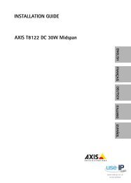
Figure 5.1 Network connection<br />
– Connect the camera to a 10/100 Base-T network.<br />
– <strong>Use</strong> screened UTP Category 5e cable with RJ45 connectors<br />
(the camera network socket is Auto MDIX compliant).<br />
– Power can be supplied to the camera via the Ethernet<br />
cable compliant with the Power-over-Ethernet<br />
(IEEE 802.3af) standard.<br />
The multicolored LED beside the Ethernet connection indicates<br />
Power (red), <strong>IP</strong> connection (green) and <strong>IP</strong> traffic (green<br />
flashing). It can be disabled in the Settings/<strong>Camera</strong> Settings/<br />
Install options menu.<br />
By default, power is supplied to the camera via the Ethernet<br />
cable, compliant with the Power-over-Ethernet standard.<br />
AR18-10-B006 | v1.1 | 2010.06 <strong>Installation</strong> and Operation Manual <strong>Bosch</strong> Security Systems
AUDIO IN AUDIO OUT<br />
Dinion <strong>IP</strong> <strong>Camera</strong> <strong>Installation</strong> | en 27<br />
5.2 Power connector<br />
ALARM<br />
1 4<br />
2 5<br />
3 6<br />
VIDEO<br />
E<br />
T<br />
H<br />
P<br />
o<br />
E<br />
12 VDC<br />
24 VAC<br />
–<br />
+<br />
DATA<br />
1 4<br />
2 5<br />
3 6<br />
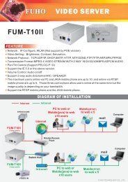
Figure 5.2<br />
Power connection<br />
5 mm<br />
0.2 in<br />
Connect power from a 24 VAC or 12 VDC class 2 power supply<br />
as follows:<br />
– <strong>Use</strong> AWG16 to 22 stranded wire or AWG16 to 26 solid<br />
wire; cut back 5 mm (0.2 in) of insulation.<br />
– Loosen the screws of the supplied 2-pole connector and<br />
insert the wires.<br />
– Tighten the screws and insert the 2-pole connector into<br />
the power socket of the camera.<br />
Note:<br />
For a DC supply the polarity is important. Incorrect polarity<br />
does not damage the camera but it will not switch on.<br />
<strong>Bosch</strong> Security Systems <strong>Installation</strong> and Operation Manual AR18-10-B006 | v1.1 | 2010.06
28 en | <strong>Installation</strong> Dinion <strong>IP</strong> <strong>Camera</strong><br />
5.3 Alarm and relay connector<br />
1<br />
Alarm<br />
4<br />
2<br />
3<br />
5<br />
6<br />
5 mm<br />
(0.2 in)<br />
Figure 5.3<br />
Alarm and relay connector pins<br />
Pin Alarm socket<br />
1 Alarm in 1<br />
2 Alarm in 2<br />
3 Relay out contact 1<br />
4 Ground<br />
5 Ground<br />
6 Relay out contact 2<br />
– Max. wire diameter AWG 22-28 for both stranded and<br />
solid; cut back 5 mm (0.2 in) of insulation.<br />
– Alarm output relay switching capability: Max voltage 30VAC<br />
or +40 VDC. Max 0.5 A continuous, 10 VA.<br />
– Alarm in: TTL logic, +5V nominal, +40 VDC max, DC coupled<br />
with 22 kOhm pull-up to +3.3 V.<br />
– Alarm in: configurable as active low or active high.<br />
– Max. 42 V allowed between camera ground and each of the<br />
relay pins.<br />
<strong>Use</strong> the alarm input to connect external alarm devices such as<br />
door contacts or sensors. A zero potential make-contact or<br />
switch can be used as the actuator (use a bounce-free contact<br />
system).<br />
<strong>Use</strong> the alarm relay output for switching external devices such<br />
as lamps or sirens.<br />
AR18-10-B006 | v1.1 | 2010.06 <strong>Installation</strong> and Operation Manual <strong>Bosch</strong> Security Systems
AUDIO IN AUDIO OUT<br />
Dinion <strong>IP</strong> <strong>Camera</strong> <strong>Installation</strong> | en 29<br />
5.4 Audio connectors<br />
GND<br />
Line<br />
ALARM<br />
1 4<br />
2 5<br />
3 6<br />
VIDEO<br />
E<br />
T<br />
H<br />
P<br />
o<br />
E<br />
12 VDC<br />
24 VAC<br />
–<br />
+<br />
1<br />
2<br />
3<br />
DATA<br />
4<br />
5<br />
6<br />
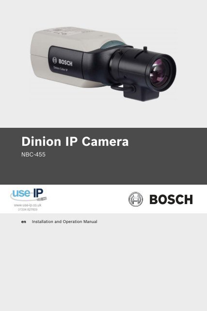
Figure 5.4 Audio connectors<br />
Connect audio devices to the Audio In and Audio Out<br />
connectors.<br />
The unit has full-duplex mono audio. The two-way<br />
communication can be used to connect a speaker or door<br />
intercom system. The audio input signal is transmitted in sync.<br />
with the video signal.<br />
Audio input: Line input level (not suitable for direct<br />
microphone signal); impedance 9 kOhm typical; 5.5 Vpp<br />
maximum input voltage.<br />
Audio output: Line output level (not suitable for direct speaker<br />
connection); impedance 16 Ohm minimum; 3 Vpp maximum<br />
output voltage.<br />
Wiring: Shielded audio connection cable is advised. Observe<br />
maximum cable lengths for audio line input and output levels.<br />
<strong>Bosch</strong> Security Systems <strong>Installation</strong> and Operation Manual AR18-10-B006 | v1.1 | 2010.06
AUDIO IN AUDIO OUT<br />
30 en | <strong>Installation</strong> Dinion <strong>IP</strong> <strong>Camera</strong><br />
5.5 Video service monitor connector<br />
ALARM<br />
1 4<br />
2 5<br />
3 6<br />
VIDEO<br />
E<br />
T<br />
H<br />
P<br />
o<br />
E<br />
12 VDC<br />
24 VAC<br />
–<br />
+<br />
1<br />
2<br />
3<br />
DATA<br />
4<br />
5<br />
6<br />
Figure 5.5 Video BNC connector<br />
1. Connect a service monitor to the composite video BNC<br />
connector to aid installation.<br />
2. Open the side panel on the camera and press the center<br />
button for longer than 2 seconds. This stops the <strong>IP</strong> video<br />
stream and enables the video analog output.<br />
AR18-10-B006 | v1.1 | 2010.06 <strong>Installation</strong> and Operation Manual <strong>Bosch</strong> Security Systems
Dinion <strong>IP</strong> <strong>Camera</strong> <strong>Installation</strong> | en 31<br />
5.6 Data connector<br />
1<br />
DATA<br />
4<br />
2<br />
3<br />
5<br />
6<br />
5 mm<br />
(0.2 in)<br />
Figure 5.6<br />
Data connector pins<br />
Pin Data socket<br />
1 Ground<br />
2 RxD / Rx+<br />
3 CTS / Rx-<br />
4 Ground<br />
5 TxD / Tx-<br />
6 RTS / Tx+<br />
The data connector is used to connect the control data coming<br />
out of the camera to external devices. RS485, RS422, and<br />
RS232 is supported by this data connection.<br />
Note:<br />
To ensure surge and electrostatic protection, keep the cable<br />
length between the camera and external device to less than 3<br />
meters.<br />
<strong>Bosch</strong> Security Systems <strong>Installation</strong> and Operation Manual AR18-10-B006 | v1.1 | 2010.06
32 en | <strong>Installation</strong> Dinion <strong>IP</strong> <strong>Camera</strong><br />
5.7 Lens mounting<br />
The camera accepts CS-mount or C-mount lenses. DC-iris<br />
lenses are recommended for best picture performance. The<br />
camera automatically detects the type of lens and optimizes<br />
performance accordingly. A spare male lens connector is<br />
provided.<br />
CAUTION!<br />
Lenses weighing more than 0.5 kg (1.1lbs) must be separately<br />
supported.<br />
<strong>Bosch</strong><br />
<strong>Bosch</strong><br />
Figure 5.7 Mounting a lens Figure 5.8 Lens connector<br />
Pin Video iris lens DC iris lens<br />
1 Supply (11.5V ±0.5, 50mA max.) Damp -<br />
2 Not used Damp +<br />
3 Video signal 1Vpp 1kOhm Drive +<br />
4 Ground Drive -<br />
Note<br />
If a short circuit is detected on the lens connector, the message<br />
LENS SHORT CIRCUIT is shown. The lens circuit is<br />
automatically disabled to avoid internal damage. Remove the<br />
lens connector and check the pin connections.<br />
AR18-10-B006 | v1.1 | 2010.06 <strong>Installation</strong> and Operation Manual <strong>Bosch</strong> Security Systems
Dinion <strong>IP</strong> <strong>Camera</strong> <strong>Installation</strong> | en 33<br />
5.8 Mounting the camera<br />
The camera can be mounted either from the top or from the<br />
bottom (1/4" 20 UNC thread).<br />
Figure 5.9<br />
Mounting a camera<br />
CAUTION!<br />
The CCD image sensors are highly sensitive and require special<br />
care for proper preformance and extended lifetime. Do not<br />
expose them, or point the camera/lens, to direct sunlight.<br />
Do not obstruct the free flow of air around the camera.<br />
<strong>Bosch</strong> Security Systems <strong>Installation</strong> and Operation Manual AR18-10-B006 | v1.1 | 2010.06
34 en | <strong>Installation</strong> Dinion <strong>IP</strong> <strong>Camera</strong><br />
5.9 Using the camera install menu<br />
Five keys, located behind the side door panel, are used for<br />
accessing the camera menu.<br />
<strong>Bosch</strong><br />
<strong>Bosch</strong><br />
To open the install menu press and hold the center key for<br />
approximately two seconds. The BNC video output is activated<br />
and the Install menu appears on the monitor.<br />
5.10 Back focus adjustment<br />
To optimize picture sharpness in both bright and low-level<br />
lighting, adjust the back focus. <strong>Use</strong> the camera's unique Lens<br />
Wizard. This ensures that the object of interest always remains<br />
in focus, even when focusing at the maximum lens iris opening<br />
(for example, at night).<br />
– When back focusing varifocal lenses, adjust to obtain a<br />
sharp picture in both wide-angle and tele positions for<br />
both far and near focus.<br />
– When back focusing zoom lenses, ensure the object of<br />
interest remains in focus throughout the entire zoom range<br />
of the lens.<br />
To adjust back focus:<br />
1. Slide open the door panel at the side of the camera.<br />
<strong>Bosch</strong><br />
2. Unlock the back focus locking button.<br />
AR18-10-B006 | v1.1 | 2010.06 <strong>Installation</strong> and Operation Manual <strong>Bosch</strong> Security Systems
Dinion <strong>IP</strong> <strong>Camera</strong> <strong>Installation</strong> | en 35<br />
3. Press and hold the center key for more than 2 seconds<br />
until the Install menu appears.<br />
4. Select Len Wizard and move cursor to the Set Back Focus<br />
Now item.<br />
5. Turn the back focus adjustment as required.<br />
<strong>Bosch</strong><br />
6. Lock the back focus locking button.<br />
<strong>Bosch</strong><br />
7. Press and hold the center key for more than 2 seconds<br />
until all the menus disappear.<br />
8. Close the side door panel.<br />
5.11 Lens adjustment<br />
5.11.1 DC-iris lens<br />
1. Unlock the back focus locking button.<br />
2. Access the Lens Wizard menu.<br />
3. Set Back Focus Now is highlighted in the menu.<br />
4. Turn the back focus adjustment as required.<br />
5. Lock the back focus locking button.<br />
6. Exit the menu.<br />
5.11.2 Manual-iris lens<br />
1. Unlock the back focus locking button.<br />
2. Adjust the lens to the maximum lens opening.<br />
3. Turn the back focus adjustment as required.<br />
4. Lock the back focus locking button.<br />
<strong>Bosch</strong> Security Systems <strong>Installation</strong> and Operation Manual AR18-10-B006 | v1.1 | 2010.06
AUDIO IN AUDIO OUT<br />
36 en | <strong>Installation</strong> Dinion <strong>IP</strong> <strong>Camera</strong><br />
5.11.3 Video-iris lens<br />
1. Unlock the back focus locking button.<br />
2. Access the Lens Wizard menu.<br />
3. Set Back Focus Now is highlighted in the menu.<br />
4. Turn the back focus adjustment as required.<br />
5. Lock the back focus locking button.<br />
6. Select Set LVL in the menu; the Level bar appears.<br />
7. Point the camera at the scene it will be mostly viewing.<br />
8. Adjust the level potentiometer located on the lens until the<br />
Level bar is in the central position.<br />
9. Exit the menu.<br />
The best performance with video iris lenses is obtained when<br />
the peak/average potentiometer of the lens matches the peak/<br />
average balance configuration setting.<br />
5.12 Reset button<br />
ALARM<br />
1 4<br />
2 5<br />
3 6<br />
VIDEO<br />
E<br />
T<br />
H<br />
P<br />
o<br />
E<br />
12 VDC<br />
24 VAC<br />
–<br />
+<br />
1<br />
2<br />
3<br />
DATA<br />
4<br />
5<br />
6<br />
Figure 5.10 Reset button<br />
With the power on, use a small pointed object to press and hold<br />
the reset button for more than 10 seconds to restore the<br />
factory defaults. This is useful to restore the default <strong>IP</strong> address<br />
or to restore a previous version of the firmware if uploading a<br />
new version fails.<br />
AR18-10-B006 | v1.1 | 2010.06 <strong>Installation</strong> and Operation Manual <strong>Bosch</strong> Security Systems
Dinion <strong>IP</strong> <strong>Camera</strong> <strong>Camera</strong> set-up | en 37<br />
6 <strong>Camera</strong> set-up<br />
The camera normally provides an optimal picture without the<br />
need for further adjustments. Configuration of the camera is<br />
carried out remotely via the network using a web browser.<br />
However, the camera also has a set-up menu in which basic<br />
installation settings (lens wizard, <strong>IP</strong> address) can be accessed.<br />
To view this menu, connect a monitor to the composite video<br />
output of the camera.<br />
6.1 <strong>Camera</strong> menu navigation<br />
Five keys are used for navigating through menu system.<br />
Up key<br />
Menu/Select key (center)<br />
Right key<br />
Down key<br />
Left key<br />
Figure 6.1<br />
Navigation<br />
– To open the install menu and enable the analog video<br />
output, press and hold the center key for approximately<br />
two seconds. This turns off the <strong>IP</strong> video stream.<br />
– <strong>Use</strong> the up or down keys to scroll through a menu.<br />
– <strong>Use</strong> the left or right keys to move through options or to set<br />
parameters.<br />
– When in a menu, quickly double-press the menu/select key<br />
to restore the selected item to its factory default.<br />
– To close all menus at once hold down the menu/select key<br />
until the menu display disappears or continually select the<br />
Exit item. (This turns the <strong>IP</strong> video stream back on.)<br />
Some menus automatically close after about two minutes; other<br />
menus have to be closed manually.<br />
<strong>Bosch</strong> Security Systems <strong>Installation</strong> and Operation Manual AR18-10-B006 | v1.1 | 2010.06
38 en | <strong>Camera</strong> set-up Dinion <strong>IP</strong> <strong>Camera</strong><br />
6.2 Install menu<br />
When the Install menu is opened, the MAC address of the unit<br />
is shown. This is factory set and cannot be changed. (To ensure<br />
that the correct MAC address is displayed, wait 20 seconds<br />
after power-up before opening the Install menu.)<br />
The items in the Install menu include the Mode selection, the<br />
Lens Wizard submenu, the Network submenu, and the Defaults<br />
submenu.<br />
Note:<br />
<strong>Camera</strong> parameter set-up is done via <strong>IP</strong>. See<br />
Section 9.6 <strong>Camera</strong> for the specific camera menus.<br />
6.2.1 Lens Wizard submenu<br />
Item Selection Description<br />
Lens type<br />
Detected<br />
Set Backfocus<br />
now<br />
Auto,<br />
Manual, DCiris,<br />
Video<br />
Auto: - automatically selects the type of<br />
lens.<br />
Manual, DC-iris, Video modes: select<br />
the matching lens type to force the<br />
camera to the correct lens mode.<br />
Shows the type of lens detected when<br />
auto lens detection is used.<br />
Select to fully open the iris. Follow the<br />
instructions below for setting the<br />
backfocus for your particular lens type.<br />
After focusing the object of interest<br />
remains in focus under bright and low<br />
light conditions.<br />
AR18-10-B006 | v1.1 | 2010.06 <strong>Installation</strong> and Operation Manual <strong>Bosch</strong> Security Systems
Dinion <strong>IP</strong> <strong>Camera</strong> <strong>Camera</strong> set-up | en 39<br />
Item Selection Description<br />
Set LVL<br />
EXIT<br />
Only for video-iris lenses.<br />
Adjust the level control on the lens to<br />
center the level detector indicator (see<br />
below).<br />
Returns to Install menu.<br />
<strong>Bosch</strong> Security Systems <strong>Installation</strong> and Operation Manual AR18-10-B006 | v1.1 | 2010.06
40 en | <strong>Camera</strong> set-up Dinion <strong>IP</strong> <strong>Camera</strong><br />
6.2.2 Network submenu<br />
To operate the camera in your network, a network-valid <strong>IP</strong><br />
address must be assigned. The factory default <strong>IP</strong> address is<br />
192.168.0.1<br />
Function Selection Description<br />
<strong>IP</strong> Address<br />
Subnet<br />
Mask<br />
Gateway<br />
DHCP<br />
Exit<br />
Enter an <strong>IP</strong> address for the camera. <strong>Use</strong><br />
LEFT/RIGHT to change position in the<br />
address, use UP/DOWN to select the digit.<br />
<strong>Use</strong> SELECT to exit the address edit<br />
screen.<br />
Enter the Subnet mask (default<br />
255.255.255.0).<br />
Enter a Gateway address.<br />
If the network has a DHCP server for<br />
dynamic <strong>IP</strong> address allocation, set this<br />
parameter to On to activate the automatic<br />
acceptance of DHCP-assigned <strong>IP</strong><br />
addresses.<br />
Return to the Install menu.<br />
The new <strong>IP</strong> address, subnet mask, and gateway address are set<br />
when leaving the menu. The camera reboots internally and the<br />
new values are set after a few seconds.<br />
6.2.3 Defaults submenu<br />
Item Selection Description<br />
Restore All No, Yes Restores all settings of the six modes<br />
to their default (factory) values. Select<br />
YES then press the Menu/Select<br />
button to restore all values.<br />
When completed the message<br />
RESTORED! is shown.<br />
AR18-10-B006 | v1.1 | 2010.06 <strong>Installation</strong> and Operation Manual <strong>Bosch</strong> Security Systems
Dinion <strong>IP</strong> <strong>Camera</strong> Browser connection | en 41<br />
7 Browser connection<br />
A computer with Microsoft Internet Explorer can be used to<br />
receive live images from the camera, control cameras, and<br />
replay stored sequences. The camera is configured over the<br />
network using the browser (or via the supplied Configuration<br />
Manager). The configuration options using the menu system of<br />
the camera itself are limited to setting up the lens and network.<br />
Note:<br />
The camera can also be connected to DIBOS 900 Series,<br />
VIDOS, <strong>Bosch</strong> Video Management System, and Divar 700 Series<br />
Digital Video Recorder, as well as third party video management<br />
systems.<br />
7.1 System requirements<br />
– Microsoft Internet Explorer version 7.0 or higher<br />
– Monitor: resolution at least 1024 × 768 pixels, 16 or 32 bit<br />
color depth<br />
– Sun JVM installed<br />
– Intranet or Internet network access<br />
The Web browser must be configured to enable Cookies to be<br />
set from the <strong>IP</strong> address of the unit.<br />
In Windows Vista, deactivate protected mode on the Security<br />
tab under Internet Options.<br />
Read the information in the System Requirements document<br />
on the product DVD supplied and, if necessary, install the<br />
required programs and controls.<br />
To play back live video images, an appropriate ActiveX must be<br />
installed on the computer. If necessary, the required software<br />
and controls can be installed from the product DVD provided.<br />
a. Insert the mini-DVD into the DVD-ROM drive of the<br />
computer. If the DVD does not start automatically,<br />
open the root directory of the DVD in Windows<br />
Explorer and double click MPEGAx.exe.<br />
b. Follow the on-screen instructions.<br />
<strong>Bosch</strong> Security Systems <strong>Installation</strong> and Operation Manual AR18-10-B006 | v1.1 | 2010.06
42 en | Browser connection Dinion <strong>IP</strong> <strong>Camera</strong><br />
7.2 Establishing the connection<br />
The camera must be assigned a valid <strong>IP</strong> address to operate on<br />
your network. The default address pre-set at the factory is<br />
192.168.0.1<br />
1. Start the Web browser.<br />
2. Enter the <strong>IP</strong> address of the camera as the URL.<br />
Note:<br />
If the connection is not established, the maximum number of<br />
possible connections may already have been reached.<br />
Depending on the device and network configuration, up to 25<br />
web browsers, or 50 VIDOS or <strong>Bosch</strong> VMS connections are<br />
supported.<br />
7.2.1 Password protection in camera<br />
A camera offers the option of limiting access across various<br />
authorization levels. If the camera is password-protected, a<br />
message to enter the password appears.<br />
1. Enter the user name and the associated password in the<br />
appropriate fields.<br />
2. Click OK. If the password is correct, the desired page is<br />
displayed.<br />
7.3 Protected network<br />
If a Radius server is used for network access control (802.1x<br />
authentication), the camera must be configured first. To<br />
configure the camera for a Radius network, connect it directly<br />
to a PC via a crossed network cable and configure the two<br />
parameters, Identity and Password. Only after these have been<br />
configured can communication with the camera via the network<br />
occur.<br />
AR18-10-B006 | v1.1 | 2010.06 <strong>Installation</strong> and Operation Manual <strong>Bosch</strong> Security Systems
Dinion <strong>IP</strong> <strong>Camera</strong> Browser connection | en 43<br />
7.4 Connecting to a hardware decoder<br />
A compatible H.264 hardware decoder with a monitor can be<br />
connected to the camera using an Ethernet network<br />
connection. <strong>Camera</strong>s are designed to automatically connect<br />
with other BV<strong>IP</strong> devices with the correct configuration. The<br />
units only need to be part of the same closed network. In this<br />
way it is possible to cover large distances with little installation<br />
or cabling effort.<br />
7.4.1 Alarm connection<br />
With the appropriate configuration, a connection between<br />
camera and decoder is established automatically when an alarm<br />
is triggered. After a short time, the live video image from the<br />
transmitter is shown on the connected monitor. In this case, no<br />
computer is needed to establish the connection<br />
Note:<br />
Make sure the devices are configured for the network<br />
environment and that the correct <strong>IP</strong> address for the remote<br />
location is set on the Alarm connections configuration page.<br />
<strong>Bosch</strong> Security Systems <strong>Installation</strong> and Operation Manual AR18-10-B006 | v1.1 | 2010.06
44 en | Browser connection Dinion <strong>IP</strong> <strong>Camera</strong><br />
7.5 Connection established<br />
When a connection is established, the LIVEPAGE is initially<br />
displayed. The application title bar displays three items:<br />
LIVEPAGE, RECORDINGS, SETTINGS.<br />
Note:<br />
The RECORDINGS link is only visible if a storage medium is<br />
available.<br />
Figure 7.1<br />
Livepage<br />
7.5.1 LIVEPAGE<br />
The LIVEPAGE is used to display and control the video stream.<br />
Refer to Section 10 Operation via the browser, page 107 for more<br />
information.<br />
7.5.2 RECORDINGS<br />
Click RECORDINGS in the application title bar to open the<br />
playback page. Refer to Section 10 Operation via the browser,<br />
page 107 for more information.<br />
7.5.3 SETTINGS<br />
Click SETTINGS in the application title bar to configure the<br />
camera and the application interface. A new page containing<br />
AR18-10-B006 | v1.1 | 2010.06 <strong>Installation</strong> and Operation Manual <strong>Bosch</strong> Security Systems
Dinion <strong>IP</strong> <strong>Camera</strong> Browser connection | en 45<br />
the configuration menu is opened. All settings are stored in the<br />
camera memory so that they are retained, even if the power is<br />
interrupted.<br />
Changes that influence the fundamental functioning of the unit<br />
(for example, firmware updates) can only be made using the<br />
configuration menu.<br />
The configuration menu tree allows all parameters of the unit to<br />
be configured. The configuration menu is divided into Basic<br />
Mode and Advanced Mode.<br />
Refer to Section 8 Basic Mode, page 46 for more information on<br />
basic settings; refer to Section 9 Advanced Mode, page 51 for<br />
more information on advanced settings.<br />
Note:<br />
It is recommended that only expert users or system<br />
administrators use the Advanced Mode.<br />
<strong>Bosch</strong> Security Systems <strong>Installation</strong> and Operation Manual AR18-10-B006 | v1.1 | 2010.06
46 en | Basic Mode Dinion <strong>IP</strong> <strong>Camera</strong><br />
8 Basic Mode<br />
8.1 Basic Mode menu tree<br />
The basic mode configuration menu allows a set of basic<br />
camera parameters to be configured.<br />
Basic Mode<br />
> Device Access<br />
> Date/Time<br />
> Network<br />
> Encoder Profile<br />
> Audio<br />
> Recording<br />
> System Overview<br />
To view the current settings:<br />
1. If necessary, click the Basic Mode menu to expand it. The<br />
sub-menus are displayed.<br />
2. Click a sub-menu. The corresponding page is opened.<br />
The settings are changed by entering new values or by selecting<br />
a pre-defined value in a list field.<br />
Saving changes<br />
After making changes in a window, click Set to send the new<br />
settings to the device and save them there.<br />
Clicking Set saves only the settings in the current window.<br />
Changes in any other windows are ignored.<br />
Click SETTINGS in the applications title bar to close the<br />
window without saving the changes.<br />
Note:<br />
Device time settings are lost after 1 hour without power if no<br />
central time server is selected.<br />
Note:<br />
When entering names do not use any special characters, for<br />
example &. Special characters are not supported by the internal<br />
recording management system.<br />
AR18-10-B006 | v1.1 | 2010.06 <strong>Installation</strong> and Operation Manual <strong>Bosch</strong> Security Systems
Dinion <strong>IP</strong> <strong>Camera</strong> Basic Mode | en 47<br />
8.2 Device Access<br />
8.2.1 <strong>Camera</strong> name<br />
Assign a name to assist in identification. This name simplifies<br />
the management of multiple devices in more extensive systems.<br />
The name is used for remote identification, for example, in the<br />
event of an alarm. Enter a name that makes it as easy as<br />
possible to identify the location unambiguously.<br />
8.2.2 Password<br />
A password prevents unauthorized access to the device. The<br />
device recognizes three authorization levels: service, user, and<br />
live.<br />
– service is the highest authorization level. Entering the<br />
correct password gives access to all the functions of the<br />
camera and allows all configuration settings to be<br />
changed.<br />
– user is the middle authorization level. This user can<br />
operate the device, play back recordings, and also control<br />
a camera but cannot change the configuration.<br />
– live is the lowest authorization level. It can only be used to<br />
view the live video image and switch between the different<br />
live image displays.<br />
<strong>Use</strong> the various authorization levels to limit access. Proper<br />
password protection is only guaranteed if all higher<br />
authorization levels are also protected with a password. For<br />
example, if a live password is assigned, a service and a user<br />
password should also be set. When assigning passwords,<br />
always start from the highest authorization level, service, and<br />
use different passwords.<br />
Password<br />
Define and change a separate password for each level while<br />
logged in as service or if the device is not protected by a<br />
password. Enter the password for the selected level.<br />
<strong>Bosch</strong> Security Systems <strong>Installation</strong> and Operation Manual AR18-10-B006 | v1.1 | 2010.06
48 en | Basic Mode Dinion <strong>IP</strong> <strong>Camera</strong><br />
Confirm password<br />
Re-enter the new password to ensure that there are no typing<br />
mistakes.<br />
The new password is only saved after clicking Set. Therefore,<br />
click Set immediately after entering and confirming the<br />
password, even if assigning a password at another level.<br />
8.3 Date/Time<br />
Device date, time and zone<br />
If there are multiple devices operating in the system or<br />
network, it is important to synchronize their internal clocks. For<br />
example, it is only possible to identify and correctly evaluate<br />
simultaneous recordings when all devices are operating on the<br />
same time.<br />
As the device time is controlled by the internal clock, it is not<br />
necessary to enter the day or date of the week. These are set<br />
automatically. The time zone in which the system is located is<br />
also set automatically.<br />
1. Click Sync to PC to apply the system time from your<br />
computer to the device.<br />
Time server <strong>IP</strong> address<br />
The camera can receive the time signal from a time server using<br />
various time server protocols and then use it to set the internal<br />
clock. The device polls the time signal automatically once every<br />
minute. Enter the <strong>IP</strong> address of a time server.<br />
Time server type<br />
Select the protocol that is supported by the selected time<br />
server. It is recommended to select the SNTP server protocol.<br />
This protocol provides high accuracy and is required for special<br />
applications and future function extensions. Select Time server<br />
if the server uses the RFC 868 protocol.<br />
Note:<br />
It is important to ensure that the date/time is correct for<br />
recording. An incorrect date/time setting could prevent correct<br />
recording.<br />
AR18-10-B006 | v1.1 | 2010.06 <strong>Installation</strong> and Operation Manual <strong>Bosch</strong> Security Systems
Dinion <strong>IP</strong> <strong>Camera</strong> Basic Mode | en 49<br />
8.4 Network<br />
<strong>Use</strong> the settings on this page to integrate the device into a<br />
network. Some changes only take effect after a reboot. In this<br />
case, the Set button changes to Set and Reboot.<br />
1. Make the desired changes.<br />
2. Click Set and Reboot.<br />
– The device is rebooted and the changed settings are<br />
activated. If the <strong>IP</strong> address, subnet mask, or gateway<br />
address is changed, then the device is only available<br />
under the new addresses after the reboot.<br />
DHCP<br />
If the network has a DHCP server for dynamic <strong>IP</strong> address<br />
allocation, set this parameter to On to activate the automatic<br />
acceptance of DHCP-assigned <strong>IP</strong> addresses.<br />
Note:<br />
Certain applications (for example, <strong>Bosch</strong> Video Management<br />
System) use the <strong>IP</strong> address for the unique assignment of the<br />
device. If using these applications, the DHCP server must<br />
support the fixed assignment between <strong>IP</strong> address and MAC<br />
address, and must be appropriately set up so that, once an <strong>IP</strong><br />
address is assigned, it is retained each time the system is<br />
rebooted.<br />
<strong>IP</strong> address<br />
Enter the desired <strong>IP</strong> address for the camera. The <strong>IP</strong> address<br />
must be valid for the network.<br />
Subnet mask<br />
Enter the appropriate subnet mask for the set <strong>IP</strong> address.<br />
Gateway address<br />
Enter the <strong>IP</strong> address of the gateway to establish a connection to<br />
a remote location in a different subnet. Otherwise, this field can<br />
remain empty (0.0.0.0).<br />
<strong>Bosch</strong> Security Systems <strong>Installation</strong> and Operation Manual AR18-10-B006 | v1.1 | 2010.06
50 en | Basic Mode Dinion <strong>IP</strong> <strong>Camera</strong><br />
8.5 Encoder Profile<br />
Select a profile for encoding the video signal. Pre-programmed<br />
profiles are available that give priority to different parameters.<br />
When a profile is selected, its details are displayed.<br />
8.6 Audio<br />
Switch the camera audio On or Off. Adjust the input and output<br />
levels with the sliders.<br />
8.7 Recording<br />
Record the images from the camera to a storage medium. For<br />
long-term authoritative images, it is essential to use a<br />
Divar 700 Series Digital Video Recorder or an appropriately<br />
sized iSCSI system.<br />
8.7.1 Storage medium<br />
1. Select the required storage medium from the list.<br />
2. Click Start to start recording or Stop to end recording.<br />
8.8 System Overview<br />
This page provides general information on the hardware and<br />
firmware system, including version numbers. No items can be<br />
changed on this page but they can be copied for information<br />
purposes when troubleshooting.<br />
AR18-10-B006 | v1.1 | 2010.06 <strong>Installation</strong> and Operation Manual <strong>Bosch</strong> Security Systems
Dinion <strong>IP</strong> <strong>Camera</strong> Advanced Mode | en 51<br />
9 Advanced Mode<br />
9.1 Advanced Mode menu tree<br />
The advanced mode configuration menu contains all camera<br />
parameters that can be configured.<br />
Advanced Mode<br />
> General<br />
> Web Interface<br />
> Encoder<br />
> <strong>Camera</strong><br />
> Recording<br />
> Alarm<br />
> Interfaces<br />
> Network<br />
> Service<br />
To view the current settings:<br />
1. Click the Advanced Mode menu to expand it. The<br />
associated menu sub-headings are displayed.<br />
2. Click a menu sub-heading to expand it.<br />
3. Click a sub-menu. The corresponding page is opened.<br />
The settings are changed by entering new values or by selecting<br />
a pre-defined value in a list field.<br />
Saving changes<br />
After making changes in a window, click Set to send the new<br />
settings to the device and save them there.<br />
Clicking Set saves only the settings in the current window.<br />
Changes in any other windows are ignored.<br />
Click SETTINGS in the applications title bar to close the<br />
window without saving the changes made.<br />
<strong>Bosch</strong> Security Systems <strong>Installation</strong> and Operation Manual AR18-10-B006 | v1.1 | 2010.06
52 en | Advanced Mode Dinion <strong>IP</strong> <strong>Camera</strong><br />
Note:<br />
Device time settings are lost after 1 hour without power if no<br />
central time server is selected.<br />
Note:<br />
When entering names do not use any special characters, for<br />
example &. Special characters are not supported by the internal<br />
recording management system.<br />
AR18-10-B006 | v1.1 | 2010.06 <strong>Installation</strong> and Operation Manual <strong>Bosch</strong> Security Systems
Dinion <strong>IP</strong> <strong>Camera</strong> Advanced Mode | en 53<br />
9.2 General<br />
General<br />
> Identification<br />
> Password<br />
> Date/Time<br />
> Display Stamping<br />
9.2.1 Identification<br />
<strong>Camera</strong> ID<br />
Each device should be assigned a unique identifier that can be<br />
entered here as an additional means of identification.<br />
<strong>Camera</strong> name<br />
Assign a name to assist in identification. This name simplifies<br />
the management of multiple devices in more extensive systems.<br />
The name is used for remote identification, for example, in the<br />
event of an alarm. Enter a name that makes it as easy as<br />
possible to identify the location unambiguously.<br />
Initiator extension<br />
Add text to an initiator name to make identification easier in<br />
large iSCSI systems. This text is added to the initiator name,<br />
separated from it by a full stop.<br />
9.2.2 Password<br />
A password prevents unauthorized access to the device. The<br />
device recognizes three authorization levels: service, user, and<br />
live.<br />
– service is the highest authorization level. Entering the<br />
correct password gives access to all the functions of the<br />
camera and allows all configuration settings to be<br />
changed.<br />
– user is the middle authorization level. This user can<br />
operate the device, play back recordings, and also control<br />
a camera but cannot change the configuration.<br />
<strong>Bosch</strong> Security Systems <strong>Installation</strong> and Operation Manual AR18-10-B006 | v1.1 | 2010.06
54 en | Advanced Mode Dinion <strong>IP</strong> <strong>Camera</strong><br />
– live is the lowest authorization level. It can only be used to<br />
view the live video image and switch between the different<br />
live image displays.<br />
<strong>Use</strong> the various authorization levels to limit access. Proper<br />
password protection is only guaranteed if all higher<br />
authorization levels are also protected with a password. For<br />
example, if a live password is assigned, a service and a user<br />
password should also be set. When assigning passwords,<br />
always start from the highest authorization level, service, and<br />
use different passwords.<br />
Password<br />
Define and change a separate password for each level while<br />
logged in as service or if the device is not protected by a<br />
password. Enter the password for the selected level.<br />
Confirm password<br />
Re-enter the new password to ensure that there are no typing<br />
mistakes.<br />
The new password is only saved after clicking Set. Therefore,<br />
click Set immediately after entering and confirming the<br />
password, even if assigning a password at another level.<br />
9.2.3 Date/Time<br />
Date format<br />
Select the required date format.<br />
Device date / Device time<br />
If there are multiple devices operating in your system or<br />
network, it is important to synchronize their internal clocks. For<br />
example, it is only possible to identify and correctly evaluate<br />
simultaneous recordings when all devices are operating on the<br />
same time.<br />
1. Enter the current date. Since the device time is controlled<br />
by the internal clock, it is not necessary to enter the day of<br />
the week – it is added automatically.<br />
AR18-10-B006 | v1.1 | 2010.06 <strong>Installation</strong> and Operation Manual <strong>Bosch</strong> Security Systems
Dinion <strong>IP</strong> <strong>Camera</strong> Advanced Mode | en 55<br />
2. Enter the current time or click Sync to PC to apply the<br />
system time from your computer to the device.<br />
Note:<br />
It is important to ensure that the date/time is correct for<br />
recording. An incorrect date/time setting could prevent correct<br />
recording.<br />
Device time zone<br />
Select the time zone in which the system is located.<br />
Daylight saving time<br />
The internal clock can switch automatically between normal<br />
and daylight saving time (DST). The device already contains the<br />
data for DST switch-overs up to the year 2015. <strong>Use</strong> this data or<br />
create alternative time saving data, if required.<br />
Note:<br />
If a table is not created, there is no automatic switching. When<br />
editing the table, note that values occur in linked pairs (DST<br />
start and end dates).<br />
First, check the time zone setting. If it is not correct, select the<br />
appropriate time zone for the system:<br />
1. Click Set.<br />
2. Click Details. A new window opens showing an empty<br />
table.<br />
3. Click Generate to fill the table with the preset values from<br />
the camera.<br />
4. Select the region or the city which is closest to the<br />
system's location from the list box below the table.<br />
5. Click one of the entries in the table to make changes. The<br />
entry is highlighted.<br />
6. Click Delete to remove the entry from the table.<br />
7. Choose other values from the list boxes under the table, to<br />
change the selected entry. Changes are immediate.<br />
8. If there are empty lines at the bottom of the table, for<br />
example after deletions, add new data by marking the row<br />
and selecting values from the list boxes.<br />
<strong>Bosch</strong> Security Systems <strong>Installation</strong> and Operation Manual AR18-10-B006 | v1.1 | 2010.06
56 en | Advanced Mode Dinion <strong>IP</strong> <strong>Camera</strong><br />
9. When finished, click OK to save and activate the table.<br />
Time server <strong>IP</strong> address<br />
The camera can receive the time signal from a time server using<br />
various time server protocols and then use it to set the internal<br />
clock. The device polls the time signal automatically once every<br />
minute. Enter the <strong>IP</strong> address of a time server.<br />
Time server type<br />
Select the protocol that is supported by the selected time<br />
server. It is recommended to select the SNTP server protocol.<br />
This protocol provides high accuracy and is required for special<br />
applications and future function extensions. Select Time server<br />
if the server uses the RFC 868 protocol.<br />
9.2.4 Display Stamping<br />
Various overlays or stamps in the video image provide<br />
important supplementary information. These overlays can be<br />
enabled individually and arranged on the image in a clear<br />
manner.<br />
<strong>Camera</strong> name stamping<br />
This field sets the position of the camera name overlay. It can<br />
be displayed at the Top, at the Bottom, or at a position of<br />
choice using the Custom option, or it can be set to Off for no<br />
overlay information.<br />
If the Custom option is selected, enter values in the X and Y<br />
position fields.<br />
Time stamping<br />
This field sets the position of the time and date overlay. It can<br />
be displayed at the Top, at the Bottom, or at a position of<br />
choice using the Custom option, or it can be set to Off for no<br />
overlay information.<br />
If the Custom option is selected, enter values in the X and Y<br />
position fields.<br />
Display milliseconds<br />
If necessary, display milliseconds for Time stamping. This<br />
information can be useful for recorded video images; however,<br />
AR18-10-B006 | v1.1 | 2010.06 <strong>Installation</strong> and Operation Manual <strong>Bosch</strong> Security Systems
Dinion <strong>IP</strong> <strong>Camera</strong> Advanced Mode | en 57<br />
it does increase the processor's computing time. Select Off if<br />
displaying milliseconds is not needed.<br />
Alarm mode stamping<br />
Select On for a text message to be overlaid in the event of an<br />
alarm. It can be displayed at a position of choice using the<br />
Custom option, or it can be set to Off for no overlay<br />
information.<br />
If the Custom option is selected, enter values in the X and Y<br />
position fields.<br />
Alarm message<br />
Enter the message to be displayed on the image in the event of<br />
an alarm. The maximum text length is 31 characters.<br />
Video watermarking<br />
Select On for the transmitted video images to be watermarked.<br />
After activation, all images are marked with a green W. A red W<br />
indicates that the sequence (live or saved) has been<br />
manipulated.<br />
<strong>Bosch</strong> Security Systems <strong>Installation</strong> and Operation Manual AR18-10-B006 | v1.1 | 2010.06
58 en | Advanced Mode Dinion <strong>IP</strong> <strong>Camera</strong><br />
9.3 Web Interface<br />
Web Interface<br />
> Appearance<br />
> LIVEPAGE Functions<br />
> Logging<br />
9.3.1 Appearance<br />
Adapt the appearance of the web interface and change the<br />
website language to meet your requirements. If necessary,<br />
replace the company's logo (top right) and the device name<br />
(top left) in the top part of the window with individual graphics.<br />
Either GIF or JPEG images can be used. The file paths must<br />
correspond to the access mode (for example,<br />
C:\Images\Logo.gif for access to local files or http://<br />
www.myhostname.com/images/logo.gif for access via the<br />
Internet/Intranet). For access via the Internet/Intranet, there<br />
must be a connection in order to display the image. The image<br />
files are not stored on the camera.<br />
To restore the original graphics, delete the entries in the<br />
Company logo and Device logo fields.<br />
Website language<br />
Select the language for the user interface here.<br />
Company logo<br />
Enter the path to a suitable image in this field. The image can<br />
be stored on a local computer, a local network, or at an Internet<br />
address.<br />
Device logo<br />
Enter the path for a suitable image for the device logo in this<br />
field. The image can be stored on a local computer, a local<br />
network, or at an Internet address.<br />
JPEG interval<br />
Specify the interval at which the individual images should be<br />
generated for the M-JPEG image on the Livepage.<br />
AR18-10-B006 | v1.1 | 2010.06 <strong>Installation</strong> and Operation Manual <strong>Bosch</strong> Security Systems
Dinion <strong>IP</strong> <strong>Camera</strong> Advanced Mode | en 59<br />
9.3.2 LIVEPAGE Functions<br />
In this window, adapt the Livepage functions to meet your<br />
requirements. Choose from a variety of different options for<br />
displaying information and controls.<br />
1. Mark the check boxes for the functions to be displayed on<br />
the Livepage. The selected elements are checked.<br />
2. Check the Livepage to see how the desired items are<br />
available.<br />
Transmit audio<br />
When selected, the audio from the camera (if on) is sent to the<br />
computer.<br />
Show alarm inputs<br />
The alarm inputs are displayed next to the video image as icons<br />
along with their assigned names. If an alarm is active, the<br />
corresponding icon changes color.<br />
Show relay outputs<br />
The relay output is shown next to the video image as an icon<br />
along with its assigned name. If a relay is switched, the icon<br />
changes color.<br />
Show VCA trajectories<br />
The trajectories (motion lines of objects) from the video<br />
content analysis are displayed in the live video image if a<br />
corresponding analysis type is activated.<br />
Show VCA metadata<br />
When video content analysis (VCA) is activated, additional<br />
information is displayed in the live video stream. For example,<br />
in Motion+ mode, the sensor areas for motion detection are<br />
marked.<br />
Show event log<br />
The event messages are displayed with the date and time in a<br />
field next to the video image.<br />
<strong>Bosch</strong> Security Systems <strong>Installation</strong> and Operation Manual AR18-10-B006 | v1.1 | 2010.06
60 en | Advanced Mode Dinion <strong>IP</strong> <strong>Camera</strong><br />
Show system log<br />
The system messages are displayed with the date and time in a<br />
field next to the video image and provide information about the<br />
establishment and termination of connections, etc.<br />
Allow snapshots<br />
Specify whether the icon for saving individual images should be<br />
displayed below the live image. Individual images can only be<br />
saved if this icon is visible.<br />
Allow local recording<br />
Specify whether the icon for saving video sequences on the<br />
local memory should be displayed below the live image. Video<br />
sequences can only be saved if this icon is visible.<br />
Path for JPEG and video files<br />
Enter the path for the storage location of individual images and<br />
video sequences saved from the Livepage. If necessary, click<br />
Browse to find a suitable folder.<br />
9.3.3 Logging<br />
Save event log<br />
Select this option to save event messages in a text file on the<br />
local computer. This file can be viewed, edited, and printed<br />
with any text editor or standard office software.<br />
File for event log<br />
Enter the path for saving the event log here. If necessary, click<br />
Browse to find a suitable folder.<br />
Save system log<br />
Select this option to save system messages in a text file on the<br />
local computer. This file can be viewed, edited, and printed<br />
with any text editor or standard office software.<br />
File for system log<br />
Enter the path for saving the system log here. If necessary, click<br />
Browse to find a suitable folder.<br />
AR18-10-B006 | v1.1 | 2010.06 <strong>Installation</strong> and Operation Manual <strong>Bosch</strong> Security Systems
Dinion <strong>IP</strong> <strong>Camera</strong> Advanced Mode | en 61<br />
9.4 Encoder<br />
Encoder<br />
> Privacy Masks<br />
> Encoder Profile<br />
> Encoder Streams<br />
> Audio<br />
9.4.1 Privacy Masks<br />
Four privacy mask areas can be defined. The activated masked<br />
areas are filled with the selected pattern in live view.<br />
1. Select the pattern to be used for all masks (Gray).<br />
2. Check the box of the mask you wish to activate.<br />
3. <strong>Use</strong> the mouse to define the area for each of the masks.<br />
9.4.2 Encoder Profile<br />
Adapt the video data transmission to the operating environment<br />
(network structure, bandwidth, data structures). The camera<br />
simultaneously generates two H.264 video streams and an<br />
M-JPEG stream (Tri-streaming). Select the compression<br />
settings of these streams individually, for example, one setting<br />
for transmissions to the Internet and one for LAN connections.<br />
The settings are made individually for each stream.<br />
Define profiles<br />
Eight definable profiles are available. The pre-programmed<br />
profiles give priority to different parameters.<br />
– High resolution 1<br />
High resolution (4CIF/D1) for high bandwidth connections<br />
– High resolution 2<br />
High resolution (4CIF/D1) with lower data rate<br />
– Low bandwidth<br />
High resolution (4CIF/D1) for low bandwidth connections<br />
– DSL<br />
High resolution (4CIF/D1) for DSL connections at<br />
500 kbps maximum<br />
<strong>Bosch</strong> Security Systems <strong>Installation</strong> and Operation Manual AR18-10-B006 | v1.1 | 2010.06
62 en | Advanced Mode Dinion <strong>IP</strong> <strong>Camera</strong><br />
– ISDN (2B)<br />
CIF resolution for ISDN connections at 100 kbps maximum<br />
– ISDN (1B)<br />
CIF resolution for ISDN connections at 50 kbps maximum<br />
– MODEM<br />
CIF resolution for analog modem connections at 22 kbps<br />
maximum<br />
– GSM<br />
CIF resolution for GSM connections<br />
Profile Configuration<br />
Profiles can be configured for use with the H.264 settings of<br />
encoder streams. Select a profile by clicking the appropriate<br />
tab. Change the name of a profile and individual parameter<br />
values within a profile.<br />
Profiles are rather complex. They include a number of<br />
parameters that interact with one another, so it is generally<br />
best to use the default profiles. Only change a profile if<br />
completely familiar with all the configuration options.<br />
The parameters as a group constitute a profile and are<br />
dependent on one another. If a setting outside the permitted<br />
range for a parameter is entered, the nearest valid value is<br />
substituted when the settings are saved.<br />
Profile name<br />
Enter a new name for the profile here.<br />
Target data rate<br />
To optimize utilization of the bandwidth in the network, limit<br />
the data rate for the camera. The target data rate should be set<br />
according to the desired picture quality for typical scenes with<br />
no excessive motion.<br />
For complex images or frequent changes of image content due<br />
to frequent movements, this limit can temporarily be exceeded<br />
up to the value entered in the Maximum data rate field.<br />
Maximum data rate<br />
This maximum data rate is not exceeded under any<br />
circumstances. Depending on the video quality settings for the<br />
AR18-10-B006 | v1.1 | 2010.06 <strong>Installation</strong> and Operation Manual <strong>Bosch</strong> Security Systems
Dinion <strong>IP</strong> <strong>Camera</strong> Advanced Mode | en 63<br />
I-frames and P-frames, this can result in individual images being<br />
skipped.<br />
The value entered here must be at least 10% higher than the<br />
value entered in the Target data rate field. If the value entered<br />
here is too low, it is automatically adjusted.<br />
Encoding interval<br />
The Encoding interval slider determines the interval at which<br />
images are encoded and transmitted. This can be particularly<br />
advantageous with low bandwidths. The image rate in ips<br />
(images per second) is displayed next to the slider.<br />
Video resolution<br />
Select the desired resolution for the video image. The following<br />
resolutions are available:<br />
– CIF<br />
352 × 288/240 pixels<br />
– 4CIF/D1<br />
704 × 576/480 pixels<br />
Expert Settings<br />
if necessary, use the expert settings to adapt the I-frame quality<br />
and the P-frame quality to specific requirements. The setting is<br />
based on the H.264 quantization parameter (QP).<br />
I-frame quality<br />
This setting adjusts the image quality of the I-frames. The basic<br />
setting Auto automatically adjusts the quality to the settings for<br />
the P-frame video quality. Alternatively, use the slider to set a<br />
value between 9 and 51. The value 9 represents the best image<br />
quality with, if necessary, a lower frame refresh rate depending<br />
on the settings for the maximum data rate. A value of 51 results<br />
in a very high refresh rate and lower image quality.<br />
P-frame quality<br />
This setting adjusts the maximum image quality of the P-frames.<br />
The basic setting Auto automatically adjusts to the optimum<br />
combination of movement and image definition (focus).<br />
Alternatively, use the slider to set a value between 9 and 51.<br />
<strong>Bosch</strong> Security Systems <strong>Installation</strong> and Operation Manual AR18-10-B006 | v1.1 | 2010.06
64 en | Advanced Mode Dinion <strong>IP</strong> <strong>Camera</strong><br />
The value 9 represents the best image quality with, if necessary,<br />
a lower frame refresh rate depending on the settings for the<br />
maximum data rate. A value of 51 results in a very high refresh<br />
rate and lower image quality.<br />
Default<br />
Click Default to return the profile to the factory default values.<br />
AR18-10-B006 | v1.1 | 2010.06 <strong>Installation</strong> and Operation Manual <strong>Bosch</strong> Security Systems
Dinion <strong>IP</strong> <strong>Camera</strong> Advanced Mode | en 65<br />
9.4.3 Encoder Streams<br />
Select H.264 Settings<br />
1. Select the codec algorithm for streams 1 and 2. The<br />
following algorithms are available<br />
– H.264 BP+ (HW decoder)<br />
– H.264 MP Low Latency<br />
2. Select the default profile for streams 1 and 2 from the<br />
eight profiles that have been defined.<br />
The algorithm properties have the following settings:<br />
H.264 BP+<br />
H.264 MP<br />
(HW decoder) Low Latency<br />
CABAC off on<br />
CAVLC on off<br />
GOP structure <strong>IP</strong> <strong>IP</strong><br />
I-frame distance 15 30<br />
Deblocking filter on on<br />
Recommended for Hardware<br />
Software decoders,<br />
decoders,<br />
PTZ and rapid<br />
Divar 700 Series image movements<br />
Preview >><br />
Previews of streams 1 and 2 can be shown.<br />
1. Click Preview >> to display a preview of the video for<br />
streams 1 and 2. the current profile is shown above the<br />
preview.<br />
2. Click 1:1 Live View below a preview to open a viewing<br />
window for that stream. Various additional items of<br />
information are shown across the top of the window.<br />
3. Click Preview
66 en | Advanced Mode Dinion <strong>IP</strong> <strong>Camera</strong><br />
JPEG stream<br />
Set the parmeters for the M-JPEG stream.<br />
– Select the Max. frame rate in images per second (<strong>IP</strong>S).<br />
– The Picture quality slider allows adjustment of the<br />
M-JPEG image quality from Low to High.<br />
Note:<br />
The JPEG resolution follows the highest resolution setting<br />
either in stream 1 or stream 2. For example, if stream 1 is 4CIF/<br />
D1 and stream 2 is CIF, the JPEG resolution will be 4CIF/D1.<br />
9.5 Audio<br />
Switch the camera audio On or Off. Adjust the input and output<br />
levels with the sliders.<br />
Note:<br />
The audio signals are sent in a separate data stream parallel to<br />
the video data, and so increase the network load. The audio<br />
data requires an additional bandwidth of approximately<br />
80 kbps for each connection. If you do not want any audio data<br />
to be transmitted, select Off.<br />
AR18-10-B006 | v1.1 | 2010.06 <strong>Installation</strong> and Operation Manual <strong>Bosch</strong> Security Systems
Dinion <strong>IP</strong> <strong>Camera</strong> Advanced Mode | en 67<br />
9.6 <strong>Camera</strong><br />
<strong>Camera</strong><br />
> ALC<br />
> Enhance<br />
> Color<br />
> Installer Options<br />
If the camera is in monochrome mode, all color-related menu<br />
items are disabled and cannot be accessed.<br />
9.6.1 ALC<br />
ALC level<br />
Adjust the video output level (-15 to 0 to +15).<br />
Shutter<br />
– Fixed - fixed mode is used with manual iris lenses. The<br />
shutter speed is set to 1/50 [1/60].<br />
– AES (auto-shutter) - the camera automatically sets the<br />
optimum shutter speed. The camera tries to maintain the<br />
selected shutter speed (1/60 [1/50], 1/100, 1/120, 1/250,<br />
1/500, 1/1000, 1/2000, 1/5000, 1/10K) as long as the light<br />
level of the scene permits.<br />
– FL - flickerless mode avoids interference from light sources<br />
(recommended for video iris or DC iris lenses only).<br />
Actual shutter<br />
Displays the actual shutter value from the camera to help<br />
compare lighting levels and optimum shutter speed during setup.<br />
Gain<br />
When the gain mode is On, the camera automatically sets the<br />
gain to the lowest possible value needed for a good picture.<br />
Actual gain<br />
Displays the actual gain value from the camera to help compare<br />
gain level with lighting levels and picture performance.<br />
<strong>Bosch</strong> Security Systems <strong>Installation</strong> and Operation Manual AR18-10-B006 | v1.1 | 2010.06
68 en | Advanced Mode Dinion <strong>IP</strong> <strong>Camera</strong><br />
NightSense<br />
NightSense extends the low-light performance of the camera.<br />
– In Auto mode, the camera automatically moves slowly to<br />
monochrome in low-light conditions.<br />
– In Forced mode, the camera remains in high-sensitivity<br />
monochrome operation.<br />
If NightSense is active, some noise or spots may appear in the<br />
picture. This is normal camera behavior. NightSense may cause<br />
some motion blur on moving objects.<br />
9.6.2 Enhance<br />
Back Light Compensation (Auto black)<br />
When ON, the video level is optimized for the center of the<br />
image. Parts outside this area may be underexposed or<br />
overexposed (this is normal).<br />
Auto black<br />
Auto black ON automatically increases the visibility of details.<br />
9.6.3 Color<br />
White balance<br />
– ATW: Auto tracking white balance allows the camera to<br />
continually adjust for optimal color reproduction.<br />
– AWB hold: Puts ATW on hold and saves the color settings.<br />
Red Gain<br />
Offsets factory white point alignment (reducing red introduces<br />
more cyan).<br />
Blue Gain<br />
Offsets factory white point alignment (reducing blue introduces<br />
more yellow).<br />
It is only necessary to change the white point offset for special<br />
scene conditions.<br />
AR18-10-B006 | v1.1 | 2010.06 <strong>Installation</strong> and Operation Manual <strong>Bosch</strong> Security Systems
Dinion <strong>IP</strong> <strong>Camera</strong> Advanced Mode | en 69<br />
9.6.4 Installer Options<br />
Synchronization<br />
Select the Synchronization method for the camera:<br />
– Line lock to lock to the power supply frequency;<br />
– Internal for free running camera operation.<br />
Ticker bar<br />
Switches a ticker bar on the live image on or off.<br />
<strong>Camera</strong> buttons<br />
Disable the <strong>Camera</strong> buttons on the camera to prevent<br />
unauthorized change of the camera settings.<br />
<strong>Camera</strong> LED<br />
Disable the <strong>Camera</strong> LED on the camera to switch it off.<br />
Show test pattern<br />
Select On to show a video test signal.<br />
Pattern<br />
Select the desired test pattern to help with installation and<br />
fault-finding.<br />
Restore all defaults<br />
Click Restore all defaults to restore the factory defaults for the<br />
camera. A confirmation screen appears. Allow 5 seconds for the<br />
camera to optimize the picture after a mode reset.<br />
Note:<br />
The default <strong>IP</strong> address is restored. Connect to the camera again<br />
using this address.<br />
<strong>Bosch</strong> Security Systems <strong>Installation</strong> and Operation Manual AR18-10-B006 | v1.1 | 2010.06
70 en | Advanced Mode Dinion <strong>IP</strong> <strong>Camera</strong><br />
9.7 Recording<br />
Recording<br />
> Storage Management<br />
> Recording Profiles<br />
> Retention Time<br />
> Recording Scheduler<br />
> Recording Status<br />
Record the images from the camera to an appropriately<br />
configured iSCSI system. For long-term authoritative images<br />
use an appropriately sized iSCSI system.<br />
A Video Recording Manager (VRM) can control all recording<br />
when accessing an iSCSI system. The VRM is an external<br />
program for configuring recording tasks for video servers. For<br />
further information, contact your local customer service at<br />
<strong>Bosch</strong> Security Systems.<br />
9.7.1 Storage Management<br />
Device manager<br />
If the VRM option is activated, the VRM Video Recording<br />
Manager manages all recording and no further settings can be<br />
configured here.<br />
Note:<br />
Activating or deactivating VRM causes the current settings to be<br />
lost; they can only be restored through reconfiguration.<br />
Recording media<br />
Select the required recording media to activate them and then<br />
configure the recording parameters.<br />
iSCSI Media<br />
If an iSCSI system is selected as the storage medium, a<br />
connection to the desired iSCSI system is needed to set the<br />
configuration parameters.<br />
AR18-10-B006 | v1.1 | 2010.06 <strong>Installation</strong> and Operation Manual <strong>Bosch</strong> Security Systems
Dinion <strong>IP</strong> <strong>Camera</strong> Advanced Mode | en 71<br />
The storage system selected must be available on the network<br />
and completely set up. Amongst other things, it must have an <strong>IP</strong><br />
address and be divided into logical drives (LUN).<br />
1. Enter the <strong>IP</strong> address of the required iSCSI destination in<br />
the iSCSI <strong>IP</strong> address field.<br />
2. If the iSCSI destination is password protected, enter this<br />
into the Password field.<br />
3. Click the Read button. The connection to the <strong>IP</strong> address is<br />
established. The Storage overview field displays the<br />
logical drives.<br />
Activating and Configuring Storage Media<br />
The storage overview displays the available storage media.<br />
Select individual media or iSCSI drives and transfer these to the<br />
Managed storage media list. Activate the storage media in this<br />
list and configure them for storage.<br />
Note:<br />
Each storage medium can only be associated with one user. If a<br />
storage medium is already being used by another user,<br />
decouple the user and connect the drive to the camera. Before<br />
decoupling, make absolutely sure that the previous user no<br />
longer needs the storage medium.<br />
1. In the Storage overview section, double-click the required<br />
storage medium, an iSCSI LUN or one of the other<br />
available drives. The medium is then added to the<br />
Managed storage media list. Newly added media is<br />
indicated in the Status column by the status Not active.<br />
2. Click Set to activate all media in the Managed storage<br />
media list. These are indicated in the Status column by the<br />
status Online.<br />
3. Check the box in the Rec. 1 or Rec. 2 column to specify<br />
which data stream should be recorded on the storage<br />
media selected. Rec. 1 stores stream 1, Rec. 2 stores<br />
stream 2.<br />
4. Check the boxes for the Overwrite older recordings<br />
option to specify which older recordings can be<br />
<strong>Bosch</strong> Security Systems <strong>Installation</strong> and Operation Manual AR18-10-B006 | v1.1 | 2010.06
72 en | Advanced Mode Dinion <strong>IP</strong> <strong>Camera</strong><br />
overwritten once the available memory capacity has been<br />
used. Recording 1 corresponds to stream 1, Recording 2<br />
corresponds to stream 2.<br />
Note:<br />
If older recordings are not allowed to be overwritten when the<br />
available memory capacity has been used, the recording in<br />
question is stopped. Specify limitations for overwriting old<br />
recordings by configuring the retention time.<br />
Formatting Storage Media<br />
Delete all recordings on a storage medium at any time. Check<br />
the recordings before deleting and back up important<br />
sequences on the computer's hard drive.<br />
1. Click a storage medium in the Managed storage media list<br />
to select it.<br />
2. Click Edit below the list. A new window opens.<br />
3. Click Formatting to delete all recordings in the storage<br />
medium.<br />
4. Click OK to close the window.<br />
Deactivating Storage Media<br />
Deactivate any storage medium from the Managed storage<br />
media list. It is then no longer used for recordings.<br />
1. Click a storage medium in the Managed storage media list<br />
to select it.<br />
2. Click Remove below the list. The storage medium is<br />
deactivated and removed from the list.<br />
AR18-10-B006 | v1.1 | 2010.06 <strong>Installation</strong> and Operation Manual <strong>Bosch</strong> Security Systems
Dinion <strong>IP</strong> <strong>Camera</strong> Advanced Mode | en 73<br />
9.7.2 Recording Profiles<br />
Define up to ten different recording profiles here, then assign<br />
these to individual days or times of day on the Recording<br />
Scheduler page. Modify the names of the recording profiles on<br />
the tabs in the Recording Scheduler page.<br />
1. Click a tab to edit the corresponding profile.<br />
2. If necessary, click Default to return all settings to their<br />
defaults.<br />
3. Click Copy Settings to copy the currently visible settings<br />
to other profiles. A window opens to select the target<br />
profiles for the copied settings.<br />
4. For each profile, click Set to save.<br />
Stream profile settings<br />
Select the profile setting that is to be used for each data stream<br />
when recording. This selection is independent of the selection<br />
for live data stream transmission. (The properties of the<br />
profiles are defined on the Encoder Profile page.)<br />
Recording includes<br />
Specify whether, in addition to video data, audio or metadata<br />
(for example alarms or VCA data) should also be recorded.<br />
Including metadata could make subsequent searches of<br />
recordings easier but it requires additional memory capacity.<br />
Without metadata, it is not possible to include video content<br />
analysis in recordings.<br />
Standard recording<br />
Select the mode for standard recordings:<br />
– Continuous: the recording proceeds continuously. If the<br />
maximum memory capacity is reached, older recordings<br />
will automatically be overwritten.<br />
– Pre-alarm: recording takes place in the pre-alarm time,<br />
during the alarm and during the post-alarm time only.<br />
– Off: no automatic recording takes place.<br />
<strong>Bosch</strong> Security Systems <strong>Installation</strong> and Operation Manual AR18-10-B006 | v1.1 | 2010.06
74 en | Advanced Mode Dinion <strong>IP</strong> <strong>Camera</strong><br />
Stream<br />
Select the data stream to be used for standard recordings. (You<br />
can select the data stream for alarm recordings separately and<br />
independently of this setting.)<br />
Alarm recording<br />
Select the Pre-alarm time from the list box.<br />
Select the Post-alarm time from the list box.<br />
Select the Alarm stream to use for alarm recording. The<br />
encoding interval for alarm recording can be selected from the<br />
predefined profiles.<br />
Alarm triggers<br />
Select the alarm type (Alarm input/ Motion/Audio alarm /<br />
Video loss alarm) that is to trigger a recording. Select the<br />
Virtual alarm sensors that are to trigger a recording, via RCP+<br />
commands or alarm scripts, for example.<br />
9.7.3 Retention Time<br />
Specify the retention times for recordings. If the available<br />
memory capacity of a medium has been used, older recordings<br />
are only overwritten if the retention time entered here has<br />
expired.<br />
Make sure that the retention time corresponds with the<br />
available memory capacity. A rule of thumb for the memory<br />
requirement is as follows: 1 GB per hour retention time with<br />
4CIF for complete frame rate and high image quality.<br />
Enter the required retention time in hours or days for each<br />
recording. Recording 1 corresponds to Stream 1, Recording 2<br />
corresponds to Stream 2.<br />
AR18-10-B006 | v1.1 | 2010.06 <strong>Installation</strong> and Operation Manual <strong>Bosch</strong> Security Systems
Dinion <strong>IP</strong> <strong>Camera</strong> Advanced Mode | en 75<br />
9.7.4 Recording Scheduler<br />
The recording scheduler allows you to link the created<br />
recording profiles to the days and times at which the camera's<br />
images are to be recorded in the event of an alarm. Schedules<br />
can be defined for weekdays and for holidays.<br />
Weekdays<br />
Assign as many time periods (in 15-minute intervals) as needed<br />
for any day of the week. Move the mouse cursor over the table —<br />
the time is displayed.<br />
1. Click the profile to be assigned in the Time periods box.<br />
2. Click a field in the table and, while holding down the left<br />
mouse button, drag the cursor across all of the fields to be<br />
assigned to the selected profile.<br />
3. <strong>Use</strong> the right mouse button to deselect any of the intervals.<br />
4. Click Select All to select all of the intervals to be assigned<br />
to the selected profile.<br />
5. Click Clear All to deselect all of the intervals.<br />
6. When finished, click Set to save the settings to the device.<br />
Holidays<br />
Define holidays whose settings will override the settings for the<br />
normal weekly schedule.<br />
1. Click the Holidays tab. Days that have already been<br />
defined are shown in the table.<br />
2. Click Add. A new window opens.<br />
3. Select the desired date from the calendar. Drag the mouse<br />
to select a range of dates. These are handled as a single<br />
entry in the table.<br />
4. Click OK to accept the selection(s). The window closes.<br />
5. Assign the defined holidays to the recording profile as<br />
described above.<br />
Delete user-defined holidays at any time.<br />
1. Click Delete in the Holidays tab. A new window opens.<br />
2. Click the date to be deleted.<br />
3. Click OK. The selection is removed from the table and the<br />
window is closed.<br />
4. Repeat for any other dates to be deleted.<br />
<strong>Bosch</strong> Security Systems <strong>Installation</strong> and Operation Manual AR18-10-B006 | v1.1 | 2010.06
76 en | Advanced Mode Dinion <strong>IP</strong> <strong>Camera</strong><br />
Profile names<br />
Change the names of the recording profiles listed in the Time<br />
periods box.<br />
1. Click a profile.<br />
2. Click Rename.<br />
3. Enter the new name and click Rename again.<br />
Activate recording<br />
After completing configuration, activate the recording schedule<br />
and start recording. Once activated, the Recording Profiles and<br />
the Recording Scheduler are deactivated and the configuration<br />
cannot be modified. Terminate recording at any time to modify<br />
the configuration.<br />
1. Click Start to activate the recording schedule.<br />
2. Click Stop to deactivate the recording schedule.<br />
Recordings that are currently running are interrupted and<br />
the configuration can be modified.<br />
Recording status<br />
The graphic indicates the recording activity. An animated<br />
graphic is seen when recording is taking place.<br />
9.7.5 Recording Status<br />
Details of the recording status are displayed here for<br />
information. These settings cannot be changed.<br />
AR18-10-B006 | v1.1 | 2010.06 <strong>Installation</strong> and Operation Manual <strong>Bosch</strong> Security Systems
Dinion <strong>IP</strong> <strong>Camera</strong> Advanced Mode | en 77<br />
9.8 Alarm<br />
Alarm<br />
> Alarm Connections<br />
> VCA<br />
> Audio Alarm<br />
> Alarm E-Mail<br />
> Alarm Task Editor<br />
9.8.1 Alarm Connections<br />
Select the response of the camera when an alarm occurs. In the<br />
event of an alarm, the device can automatically connect to a<br />
pre-defined <strong>IP</strong> address. The device can contact up to ten <strong>IP</strong><br />
addresses in the order listed until a connection is established.<br />
Connect on alarm<br />
Select On so that the camera automatically connects to a predefined<br />
<strong>IP</strong> address in the event of an alarm. Select Follows<br />
input 1 so that the device maintains the connection for as long<br />
as an alarm exists.<br />
Number of destination <strong>IP</strong> address<br />
Specify the numbers of the <strong>IP</strong> addresses to be contacted in the<br />
event of an alarm. The device contacts the remote locations one<br />
after the other in the numbered sequence until a connection is<br />
made.<br />
Destination <strong>IP</strong> address<br />
For each number, enter the corresponding <strong>IP</strong> address for the<br />
desired remote station.<br />
Destination password<br />
If the remote station is password protected, enter the<br />
password here.<br />
Only ten passwords can be defined here. Define a general<br />
password if more than ten connections are required, for<br />
example, when connections are initiated by a controlling<br />
<strong>Bosch</strong> Security Systems <strong>Installation</strong> and Operation Manual AR18-10-B006 | v1.1 | 2010.06
78 en | Advanced Mode Dinion <strong>IP</strong> <strong>Camera</strong><br />
system such as VIDOS or <strong>Bosch</strong> Video Management System.<br />
The camera connects to all remote stations protected by the<br />
same general password. To define a general password:<br />
1. Select 10 in the Number of destination <strong>IP</strong> address list<br />
box.<br />
2. Enter 0.0.0.0 in the Destination <strong>IP</strong> address field.<br />
3. Enter the password in the Destination password field.<br />
4. Set the user password of all the remote stations to be<br />
accessed using this password.<br />
Setting destination 10 to the <strong>IP</strong>-address 0.0.0.0 overrides its<br />
function as the tenth address to try.<br />
Video transmission<br />
If the device is operated behind a firewall, select TCP (HTTP<br />
port) as the transfer protocol. For use in a local network, select<br />
UDP.<br />
Please note that in some circumstances, in the event of an<br />
alarm, a larger bandwidth must be available on the network for<br />
additional video images (if Multicast operation is not possible).<br />
To enable Multicast operation, select the UDP option for the<br />
Video transmission parameter here and on the Network page.<br />
Remote port<br />
Select a browser port, depending on the network configuration.<br />
The ports for HTTPS connections are only available if the On<br />
option in SSL encryption is selected.<br />
Video output<br />
If it is known which device is being used as the receiver, select<br />
the analog video output to which the signal should be switched.<br />
If the destination device is unknown, it is advisable to select the<br />
First available option. In this case, the image is placed on the<br />
first free video output. This is an output on which there is no<br />
signal. The connected monitor only displays images when an<br />
alarm is triggered. If a particular video output is selected and a<br />
split image is set for this output on the receiver, select the<br />
decoder from Decoder in the receiver that is to be used to<br />
display the alarm image. Refer to the destination device<br />
AR18-10-B006 | v1.1 | 2010.06 <strong>Installation</strong> and Operation Manual <strong>Bosch</strong> Security Systems
Dinion <strong>IP</strong> <strong>Camera</strong> Advanced Mode | en 79<br />
documentation concerning image display options and available<br />
video outputs.<br />
Decoder<br />
Select a decoder of the receiver to display the alarm image. The<br />
decoder selected has an impact on the position of the image in<br />
a split screen.<br />
SSL encryption<br />
SSL encryption protects data used for establishing a<br />
connection, such as the password. By selecting On, only<br />
encrypted ports are available for the Remote port parameter.<br />
SSL encryption must be activated and configured on both sides<br />
of a connection. The appropriate certificates must also have<br />
been uploaded. Configure and activate encryption for media<br />
data (video, metadata) on the Encryption page.<br />
Auto-connect<br />
Select On to automatically re-established a connection to one<br />
of the previously specified <strong>IP</strong> addresses after each reboot,<br />
connection breakdown, or network failure.<br />
Audio<br />
Select On to transmit the audio stream with an alarm<br />
connection.<br />
<strong>Bosch</strong> Security Systems <strong>Installation</strong> and Operation Manual AR18-10-B006 | v1.1 | 2010.06
80 en | Advanced Mode Dinion <strong>IP</strong> <strong>Camera</strong><br />
9.8.2 Video Content Analyses (VCA)<br />
The camera has integrated VCA which can detect and analyze<br />
changes in the signal using image processing algorithms. Such<br />
changes can be due to movements in the camera's field of view.<br />
Select various VCA configurations and adapt these to your<br />
application, as required. The Silent MOTION+ configuration is<br />
active by default. In this configuration, metadata is created to<br />
facilitate searches of recordings, however, no alarm is<br />
triggered.<br />
1. Select a VCA configuration and make the required settings.<br />
2. If necessary, click the Default button to return all settings<br />
to their default values.<br />
Note:<br />
If there is not enough computing power, priority is given to live<br />
images and recordings. This can lead to impairment of the VCA<br />
system. Observe the processor load and optimize the encoder<br />
settings or the VCA settings if necessary, or turn off VCA<br />
completely.<br />
AR18-10-B006 | v1.1 | 2010.06 <strong>Installation</strong> and Operation Manual <strong>Bosch</strong> Security Systems
Dinion <strong>IP</strong> <strong>Camera</strong> Advanced Mode | en 81<br />
9.8.3 VCA configuration- Profiles<br />
Configure two profiles with different VCA configurations. Save<br />
profiles on your computer's hard drive and load saved profiles<br />
from there. This can be useful if testing a number of different<br />
configurations. Save a functioning configuration and test new<br />
settings. <strong>Use</strong> the saved configuration to restore the original<br />
settings at any time.<br />
1. Select a VCA profile and enter the required settings.<br />
2. If necessary, click Default to return all settings to default<br />
values.<br />
3. Click the Save... to save the profile settings to another file.<br />
A new window opens in which to specify the file name and<br />
where to save it.<br />
4. Click Load... to load a saved profile. A new window opens<br />
in which to select the profile file and specify where to save<br />
the file.<br />
To rename a profile:<br />
1. To rename the file, click the icon to the right of the list field<br />
and enter the new profile name in the field.<br />
2. Click the icon again. The new profile name is saved.<br />
The current alarm status is displayed for information purposes.<br />
Aggregation time (s)<br />
Set an aggregation time of between 0 and 20 seconds. The<br />
aggregation time always starts when an alarm event occurs. It<br />
extends the alarm event by the value set. This prevents alarm<br />
events that occur in quick succession from triggering several<br />
alarms and successive events in a rapid sequence. No further<br />
alarm is triggered during the aggregation time.<br />
The post-alarm time set for alarm recordings only starts once<br />
the aggregation time has expired.<br />
Analysis type<br />
Select the required analysis algorithm. By default, only Motion+<br />
is available — this offers a motion detector and essential<br />
recognition of tampering.<br />
<strong>Bosch</strong> Security Systems <strong>Installation</strong> and Operation Manual AR18-10-B006 | v1.1 | 2010.06
82 en | Advanced Mode Dinion <strong>IP</strong> <strong>Camera</strong><br />
Metadata is always created for a video content analysis, unless<br />
this was explicitly excluded. Depending on the analysis type<br />
selected and the relevant configuration, additional information<br />
overlays the video image in the preview window next to the<br />
parameter settings. With the Motion+ analysis type, for<br />
example, the sensor fields in which motion is recorded are<br />
marked with rectangles.<br />
Note:<br />
Additional analysis algorithms with comprehensive functions,<br />
such as IVMD and IVA, are available from <strong>Bosch</strong> Security<br />
Systems.<br />
Motion detector<br />
Motion detection is available for the Motion+ analysis type. For<br />
the detector to function, the following conditions must be met:<br />
– Analysis must be activated.<br />
– At least one sensor field must be activated.<br />
– The individual parameters must be configured to suit the<br />
operating environment and the desired responses.<br />
– The sensitivity must be set to a value greater than zero.<br />
Note:<br />
Reflections of light (from glass surfaces, etc.), lights switching<br />
on and off, or changes in the light level caused by cloud<br />
movement on a sunny day can trigger unintended responses<br />
from the motion detector and generate false alarms. Run a<br />
series of tests at different times of the day and night to ensure<br />
that the video sensor is operating as intended. For indoor<br />
surveillance, ensure constant lighting of the areas during the<br />
day and at night.<br />
Sensitivity<br />
Sensitivity is available for the Motion+ analysis type. The basic<br />
sensitivity of the motion detector can be adjusted for the<br />
environmental conditions to which the camera is subject. The<br />
sensor reacts to variations in the brightness of the video image.<br />
The darker the observation area, the higher the value that must<br />
be selected.<br />
AR18-10-B006 | v1.1 | 2010.06 <strong>Installation</strong> and Operation Manual <strong>Bosch</strong> Security Systems
Dinion <strong>IP</strong> <strong>Camera</strong> Advanced Mode | en 83<br />
Minimum object size<br />
Specify the number of sensor fields that a moving object must<br />
cover to generate an alarm. This setting prevents objects that<br />
are too small from triggering an alarm. A minimum value of 4 is<br />
recommended. This value corresponds to four sensor fields.<br />
Debounce time 1 s<br />
The debounce time prevents very brief alarm events from<br />
triggering individual alarms. If the Debounce time 1 s option is<br />
activated, an alarm event must last at least 1 second to trigger<br />
an alarm.<br />
Selecting the area<br />
Select the areas of the image to be monitored by the motion<br />
detector. The video image is subdivided into square sensor<br />
fields. Activate or deactivate each of these fields individually. To<br />
exclude particular regions of the camera's field of view from<br />
monitoring due to continuous movement (by a tree in the wind,<br />
for example), the relevant fields can be deactivated.<br />
1. Click Select Area to configure the sensor fields. A new<br />
window opens.<br />
2. If necessary, click Clear All first to clear the current<br />
selection (fields marked red).<br />
3. Left-click the fields to be activated. Activated fields are<br />
marked red.<br />
4. If necessary, click Select All to select the entire videoframe<br />
for monitoring.<br />
5. Right-click any fields to deactivate.<br />
6. Click OK to save the configuration.<br />
7. Click the close button (X) in the window title bar to close<br />
the window without saving the changes.<br />
Tamper detection<br />
Detect tampering of cameras and video cables by means of<br />
various options. Run a series of tests at different times of the<br />
day and night to ensure that the video sensor is operating as<br />
intended.<br />
<strong>Bosch</strong> Security Systems <strong>Installation</strong> and Operation Manual AR18-10-B006 | v1.1 | 2010.06
84 en | Advanced Mode Dinion <strong>IP</strong> <strong>Camera</strong><br />
Sensitivity and Trigger delay (s) can only be changed if<br />
Reference check is selected.<br />
Sensitivity<br />
The basic sensitivity of the tamper detection can be adjusted<br />
for the environmental conditions to which the camera is<br />
subject. The algorithm reacts to the differences between the<br />
reference image and the current video image. The darker the<br />
observation area, the higher the value that must be selected.<br />
Trigger delay (s)<br />
Set delayed alarm triggering here. The alarm is only triggered<br />
after a set time interval in seconds has elapsed and then only if<br />
the triggering condition still exists. If the original condition has<br />
been restored before this time interval elapses, the alarm is not<br />
triggered. This avoids false alarms triggered by short-term<br />
changes, for example, cleaning activities in the direct field of<br />
vision of the camera.<br />
Global change (slider)<br />
Set how large the global change in the video image must be for<br />
an alarm to be triggered. This setting is independent of the<br />
sensor fields selected under Select Area. Set a high value if<br />
fewer sensor fields need to change to trigger an alarm. With a<br />
low value, it is necessary for changes to occur simultaneously in<br />
a large number of sensor fields to trigger an alarm. This option<br />
allows detection, independently of motion alarms, manipulation<br />
of the orientation or location of a camera resulting from turning<br />
the camera mount bracket, for example.<br />
Global change<br />
Activate this function if the global change, as set with the<br />
Global change slide control, should trigger an alarm.<br />
Scene too bright<br />
Activate this function if tampering associated with exposure to<br />
extreme light (for instance, shining a flashlight directly on the<br />
objective) should trigger an alarm. The average brightness of<br />
the scene provides a basis for recognition.<br />
AR18-10-B006 | v1.1 | 2010.06 <strong>Installation</strong> and Operation Manual <strong>Bosch</strong> Security Systems
Dinion <strong>IP</strong> <strong>Camera</strong> Advanced Mode | en 85<br />
Scene too dark<br />
Activate this function if tampering associated with covering the<br />
objective (for instance, by spraying paint on it) should trigger<br />
an alarm. The average brightness of the scene provides a basis<br />
for recognition.<br />
Scene too noisy<br />
Activate this function if tampering associated with EMC<br />
interference (noisy scene as the result of a strong interference<br />
signal in the vicinity of the video lines) should trigger an alarm.<br />
Reference check<br />
Save a reference image that can be continuously compared with<br />
the current video image. If the current video image in the<br />
marked areas differs from the reference image, an alarm is<br />
triggered. This detects tampering that would otherwise not be<br />
detected, for example, if the camera is turned.<br />
1. Click Reference to save the currently visible video- image<br />
as a reference.<br />
2. Click Select Area and select the areas in the reference<br />
image that are to be monitored.<br />
3. Check the box Reference check to activate the on-going<br />
check. The stored reference image is displayed in black<br />
and white below the current video image, and the selected<br />
areas are marked in yellow.<br />
4. Select the Disappearing edges or Appearing edges option<br />
to specify the reference check once again.<br />
Disappearing edges<br />
The area selected in the reference image should contain a<br />
prominent structure. If this structure is concealed or moved,<br />
the reference check triggers an alarm. If the selected area is too<br />
homogenous, so that concealing and moving the structure<br />
would not trigger an alarm, then an alarm is triggered<br />
immediately to indicate the inadequate reference image.<br />
<strong>Bosch</strong> Security Systems <strong>Installation</strong> and Operation Manual AR18-10-B006 | v1.1 | 2010.06
86 en | Advanced Mode Dinion <strong>IP</strong> <strong>Camera</strong><br />
Appearing edges<br />
Select this option if the selected area of the reference image<br />
includes a largely homogenous surface. If structures appear in<br />
this area, then an alarm is triggered.<br />
Selecting the area<br />
Select the image areas in the reference image that are to be<br />
monitored. The video image is subdivided into square fields.<br />
Activate or deactivate each of these fields individually.<br />
Select only those areas for reference monitoring in which no<br />
movement takes place and that are always evenly lit, as false<br />
alarms could otherwise be triggered.<br />
1. Click Select Area to configure the sensor fields. A new<br />
window opens.<br />
2. If necessary, click Clear All first to clear the current<br />
selection (fields marked yellow).<br />
3. Left-click the fields to be activated. Activated fields are<br />
marked yellow.<br />
4. If necessary, click Select All to select the entire videoframe<br />
for monitoring.<br />
5. Right-click any fields to deactivate.<br />
6. Click OK to save the configuration.<br />
7. Click the close button (X) in the window title bar to close<br />
the window without saving the changes.<br />
AR18-10-B006 | v1.1 | 2010.06 <strong>Installation</strong> and Operation Manual <strong>Bosch</strong> Security Systems
Dinion <strong>IP</strong> <strong>Camera</strong> Advanced Mode | en 87<br />
9.8.4 VCA configuration - Scheduled<br />
A scheduled configuration allows you to link a VCA profile with<br />
the days and times at which the video content analysis is to be<br />
active. Schedules can be defined for weekdays and for holidays.<br />
Weekdays<br />
Link any number of 15-minute intervals with the VCA profiles for<br />
each day of the week. Moving the mouse cursor over the table<br />
displays the time below it. This aids orientation.<br />
1. Click the profile to link in the Time periods field.<br />
2. Click in a field in the table, hold down the mouse button<br />
and drag the cursor over all the periods to be assigned to<br />
the selected profile.<br />
3. <strong>Use</strong> the right mouse button to deselect any of the intervals.<br />
4. Click Select All to link all time intervals to the selected<br />
profile.<br />
5. Click Clear All to deselect all of the intervals.<br />
6. When finished, click Set to save the settings in the device.<br />
Holidays<br />
Define holidays on which a profile should be active that are<br />
different to the standard weekly schedule.<br />
1. Click the Holidays tab. Any days that have already been<br />
selected are shown in the table.<br />
2. Click Add. A new window opens.<br />
3. Select the desired date from the calendar. Select several<br />
consecutive calendar days by holding down the mouse<br />
button. These will later be displayed as a single entry in the<br />
table.<br />
4. Click OK to accept the selection. The window closes.<br />
5. Assign the individual holidays to the VCA profiles, as<br />
described above.<br />
Deleting Holidays<br />
Delete defined holidays at any time:<br />
1. Click Delete. A new window opens.<br />
2. Click the date to delete.<br />
<strong>Bosch</strong> Security Systems <strong>Installation</strong> and Operation Manual AR18-10-B006 | v1.1 | 2010.06
88 en | Advanced Mode Dinion <strong>IP</strong> <strong>Camera</strong><br />
3. Click OK. The item is deleted from the table and the<br />
window closes.<br />
4. The process must be repeated for deleting additional days.<br />
AR18-10-B006 | v1.1 | 2010.06 <strong>Installation</strong> and Operation Manual <strong>Bosch</strong> Security Systems
Dinion <strong>IP</strong> <strong>Camera</strong> Advanced Mode | en 89<br />
9.8.5 VCA configuration - Event triggered<br />
This configuration allows you to stipulate that the video content<br />
analysis is only to be activated when triggered by an event. As<br />
long as no trigger is activated, the Silent MOTION+<br />
configuration in which metadata is created is active; this<br />
metadata facilitates searches of recordings, but does not<br />
trigger an alarm.<br />
Trigger<br />
Select a physical alarm or a virtual alarm as a trigger. A virtual<br />
alarm is created using software, with RCP+ commands or alarm<br />
scripts, for example.<br />
Trigger active<br />
Select the VCA configuration here that is to be enabled via an<br />
active trigger. A green check mark to the right of the list field<br />
indicates that the trigger is active.<br />
Trigger inactive<br />
Select the VCA configuration here that is to be activated if the<br />
trigger is not active. A green check mark to the right of the list<br />
field indicates that the trigger is inactive.<br />
Delay (s)<br />
Select the delay period for the reaction of the video content<br />
analysis to trigger signals. The alarm is only triggered after a set<br />
time interval in seconds has elapsed and then only if the<br />
triggering condition still exists. If the original condition has<br />
been restored before this time interval elapses, the alarm is not<br />
triggered. A delay period may be useful in avoiding false alarms<br />
or frequent triggering. During the delay period, the Silent<br />
MOTION+ configuration is always enabled.<br />
<strong>Bosch</strong> Security Systems <strong>Installation</strong> and Operation Manual AR18-10-B006 | v1.1 | 2010.06
90 en | Advanced Mode Dinion <strong>IP</strong> <strong>Camera</strong><br />
9.8.6 Audio Alarm<br />
Create alarms based on audio signals. Configure signal<br />
strengths and frequency ranges so that false alarms, for<br />
example, machine noise or background noise, are avoided.<br />
Set up normal audio transmission before configuring the audio<br />
alarm.<br />
Audio alarm<br />
Select On for the device to generate audio alarms.<br />
Name<br />
The name makes it easier to identify the alarm in extensive<br />
video monitoring systems, for example with the VIDOS and<br />
<strong>Bosch</strong> Video Management System programs. Enter a unique and<br />
clear name here.<br />
Signal Ranges<br />
Exclude particular signal ranges in order to avoid false alarms.<br />
For this reason the total signal is divided into 13 tonal ranges<br />
(mel scale). Check or uncheck the boxes below the graphic to<br />
include or exclude individual ranges.<br />
Threshold<br />
Set up the threshold on the basis of the signal visible in the<br />
graphic Set the threshold using the slide control or,<br />
alternatively, move the white line directly in the graphic using<br />
the mouse.<br />
Sensitivity<br />
<strong>Use</strong> this setting to adapt the sensitivity to the sound<br />
environment and effectively suppress individual signal peaks. A<br />
high value represents a high level of sensitivity.<br />
AR18-10-B006 | v1.1 | 2010.06 <strong>Installation</strong> and Operation Manual <strong>Bosch</strong> Security Systems
Dinion <strong>IP</strong> <strong>Camera</strong> Advanced Mode | en 91<br />
9.8.7 Alarm E-Mail<br />
As an alternative to automatic connecting, alarm states can also<br />
be documented by e-mail. This makes it possible to notify a<br />
recipient who does not have a video receiver. In this case, the<br />
camera automatically sends an e-mail to a user-defined e-mail<br />
address.<br />
Send alarm e-mail<br />
Select On for the device to automatically send an alarm e-mail<br />
in the event of an alarm.<br />
Mail server <strong>IP</strong> address<br />
Enter the <strong>IP</strong> address of a mail server that operates on the SMTP<br />
standard (Simple Mail Transfer Protocol). Outgoing e-mails are<br />
sent to the mail server via the address entered. Otherwise,<br />
leave the box blank (0.0.0.0).<br />
SMTP user name<br />
Enter a registered user name for the chosen mail server.<br />
SMTP password<br />
Enter the required password for the registered user name.<br />
Format<br />
Select the data format of the alarm message.<br />
– Standard (with JPEG): e-mail with JPEG image file<br />
attachment.<br />
– SMS: e-mail in SMS format to an e-mail-to-SMS gateway<br />
(for example, to send an alarm by cellphone) without an<br />
image attachment.<br />
When a cellphone is used as the receiver, make sure to activate<br />
the e-mail or SMS function, depending on the format, so that<br />
these messages can be received. Obtain information on<br />
operating your cellphone from your cellphone provider.<br />
Attach JPEG from camera<br />
Check the box to specify that JPEG images are sent from the<br />
camera.<br />
<strong>Bosch</strong> Security Systems <strong>Installation</strong> and Operation Manual AR18-10-B006 | v1.1 | 2010.06
92 en | Advanced Mode Dinion <strong>IP</strong> <strong>Camera</strong><br />
Destination address<br />
Enter the e-mail address for alarm e-mails here. The maximum<br />
address length is 49 characters.<br />
Sender name<br />
Enter a unique name for the e-mail sender, for example, the<br />
location of the device. This makes it easier to identify the origin<br />
of the e-mail.<br />
Test e-mail<br />
Click Send Now to test the e-mail function. An alarm e-mail is<br />
immediately created and sent.<br />
AR18-10-B006 | v1.1 | 2010.06 <strong>Installation</strong> and Operation Manual <strong>Bosch</strong> Security Systems
Dinion <strong>IP</strong> <strong>Camera</strong> Advanced Mode | en 93<br />
9.8.8 Alarm Task Editor<br />
Editing scripts on this page overwrites all settings and entries<br />
on the other alarm pages. This procedure cannot be reversed.<br />
To edit this page, you should have programming knowledge and<br />
be familiar with the information in the Alarm Task Script<br />
Language document and the English language. The document<br />
can be found on the product DVD supplied.<br />
As an alternative to the alarm settings on the various alarm<br />
pages, enter the desired alarm functions in script form here.<br />
This will overwrite all settings and entries on the other alarm<br />
pages.<br />
1. Click Examples under the Alarm Task Editor field to see<br />
some script examples. A new window opens.<br />
2. Enter new scripts in the Alarm Task Editor field or change<br />
existing scripts in line with your requirements.<br />
3. When finished, click Set to transmit the scripts to the<br />
device. If the transfer was successful, the message Script<br />
successfully parsed. is displayed over the text field. If it<br />
was not successful, an error message is displayed with<br />
further information.<br />
<strong>Bosch</strong> Security Systems <strong>Installation</strong> and Operation Manual AR18-10-B006 | v1.1 | 2010.06
94 en | Advanced Mode Dinion <strong>IP</strong> <strong>Camera</strong><br />
9.9 Interfaces<br />
Interfaces<br />
> Alarm input<br />
> Relay<br />
> COM1<br />
9.9.1 Alarm input<br />
Configure the alarm triggers for the camera.<br />
Select N.C. (Normally Closed) if the alarm is to be triggered by<br />
closing the contact.<br />
Select N.O. (Normally Open) if the alarm is to be triggered by<br />
opening the contact.<br />
Name<br />
Enter a name for the alarm input. This is then displayed below<br />
the icon for the alarm input on the LIVEPAGE (if configured).<br />
Action<br />
Select the camera mode to switch to when alarm input 1 is<br />
triggered. See Section 9.8.8 Alarm Task Editor, page 93, for<br />
information on alarm actions based on alarm inputs.<br />
9.9.2 Relay<br />
Configure the switching behavior of the relay output.<br />
Select different events that automatically activate an output.<br />
For example, turn on a floodlight by triggering a motion alarm<br />
and then turn the light off again when the alarm has stopped.<br />
Idle state<br />
Select Open for the relay to operate as an N.O. contact, or<br />
select Closed if the relay is to operate as an N.C. contact.<br />
Select<br />
Select External device or Motion+/IVA to trigger the relay.<br />
AR18-10-B006 | v1.1 | 2010.06 <strong>Installation</strong> and Operation Manual <strong>Bosch</strong> Security Systems
Dinion <strong>IP</strong> <strong>Camera</strong> Advanced Mode | en 95<br />
Relay name<br />
The relay can be assigned a name here. The name is shown on<br />
the button next to Trigger relay. The LIVEPAGE can also be<br />
configured to display the name next to the relay icon.<br />
Trigger relay<br />
Click the button to switch the relay manually (for example, for<br />
testing purposes or to operate a door opener).<br />
9.9.3 COM1<br />
Configure the data connector for the camera.<br />
Serial port function<br />
Select a controllable unit from the list. If you wish to use the<br />
serial port to transmit transparent data, select Transparent.<br />
Select Terminal if you wish to operate the unit from a terminal.<br />
After selecting a unit, the remaining parameters in the window<br />
are set automatically and should not be changed.<br />
<strong>Camera</strong> ID<br />
If necessary, enter the ID of the peripheral you wish to control<br />
(for example a dome camera or pan/tilt head).<br />
Baud rate<br />
Select the value for the transmission rate in bps.<br />
Data bits<br />
The number of data bits per character cannot be changed.<br />
Stop bits<br />
Select the number of stop bits per character.<br />
Parity check<br />
Select the type of parity check.<br />
Interface mode<br />
Select the desired protocol for the serial interface.<br />
<strong>Bosch</strong> Security Systems <strong>Installation</strong> and Operation Manual AR18-10-B006 | v1.1 | 2010.06
96 en | Advanced Mode Dinion <strong>IP</strong> <strong>Camera</strong><br />
9.10 Network<br />
Network<br />
> Network<br />
> Advanced<br />
> Multicasting<br />
> JPEG Posting<br />
> Encryption<br />
9.10.1 Network<br />
The settings on this page are used to integrate the device into a<br />
network. Some changes only take effect after a reboot. In this<br />
case Set changes to Set and Reboot.<br />
1. Make the desired changes.<br />
2. Click Set and Reboot.<br />
The device is rebooted and the changed settings are activated.<br />
If the <strong>IP</strong> address, subnet mask, or gateway address is changed,<br />
then the device is only available under the new addresses after<br />
the reboot.<br />
Automatic <strong>IP</strong> assignment<br />
If a DHCP server is employed in the network for the dynamic<br />
assignment of <strong>IP</strong> addresses, activate acceptance of <strong>IP</strong><br />
addresses automatically assigned to the device.<br />
Certain applications (VIDOS, <strong>Bosch</strong> Video Management System,<br />
Archive Player, Configuration Manager) use the <strong>IP</strong> address for<br />
the unique assignment of the device. If using these<br />
applications, the DHCP server must support the fixed<br />
assignment between <strong>IP</strong> address and MAC address, and must be<br />
appropriately set up so that, once an <strong>IP</strong> address is assigned, it<br />
is retained each time the system is rebooted.<br />
<strong>IP</strong> address<br />
Enter the desired <strong>IP</strong> address for the camera. The <strong>IP</strong> address<br />
must be valid for the network.<br />
AR18-10-B006 | v1.1 | 2010.06 <strong>Installation</strong> and Operation Manual <strong>Bosch</strong> Security Systems
Dinion <strong>IP</strong> <strong>Camera</strong> Advanced Mode | en 97<br />
Subnet mask<br />
Enter the appropriate subnet mask for the set <strong>IP</strong> address.<br />
Gateway address<br />
For the device to establish a connection to a remote location in<br />
a different subnet, enter the <strong>IP</strong> address of the gateway here.<br />
Otherwise, this field can remain empty (0.0.0.0).<br />
DNS server address<br />
The device is easier to access if it is listed on a DNS server. For<br />
example, to establish an Internet connection to the camera, it is<br />
sufficient to enter the name given to the device on the DNS<br />
server as a URL in the browser. Enter the DNS server's <strong>IP</strong><br />
address. Servers are supported for secure and dynamic DNS.<br />
Details >><br />
Video transmission<br />
If the device is used behind a firewall, TCP (Port 80) should be<br />
selected as the transmission protocol. For use in a local<br />
network, choose UDP.<br />
Multicast operation is only possible with the UDP protocol. The<br />
TCP protocol does not support multicast connections. The MTU<br />
value in UDP mode is 1514 bytes.<br />
HTTP browser port<br />
Select a different HTTP browser port from the list if required.<br />
The default HTTP port is 80. To limit connection to HTTPS,<br />
deactivate the HTTP port. To do this, activate the Off option.<br />
HTTPS browser port<br />
To limit browser access to encrypted connections, choose an<br />
HTTPS port from the list. The standard HTTPS port is 443.<br />
Select the Off option to deactivate HTTPS ports and limit<br />
connections to unencrypted ports.<br />
The camera uses the TLS 1.0 protocol. Ensure that the browser<br />
has been configured to support this protocol. Also ensure that<br />
Java application support is activated (in the Java Plug-in<br />
Control Panel of the Windows Control Panel).<br />
<strong>Bosch</strong> Security Systems <strong>Installation</strong> and Operation Manual AR18-10-B006 | v1.1 | 2010.06
98 en | Advanced Mode Dinion <strong>IP</strong> <strong>Camera</strong><br />
To limit connections to SSL encryption, set the Off option in<br />
the HTTP browser port, the RCP+ port, and Telnet support. This<br />
deactivates all unencrypted connections allowing connections<br />
on the HTTPS port only.<br />
Configure and activate encryption for media data (video, audio,<br />
metadata) on the Encryption page.<br />
RCP+ port 1756<br />
Activating RCP+ port 1756 allows unencrypted connections on<br />
this port. To allow only encrypted connections, set the Off<br />
option to deactivate the port.<br />
Telnet support<br />
Activating Telenet support allows unencrypted connections on<br />
this port. To allow only encrypted connections, set the Off<br />
option to deactivate telnet support, making telnet connections<br />
impossible.<br />
Interface mode ETH<br />
If necessary, select the Ethernet link type for interface ETH.<br />
Depending on the device connected, it may be necessary to<br />
select a special operation type.<br />
Network MSS (Byte)<br />
Set the maximum segment size for the <strong>IP</strong> packet's user data<br />
here. This gives the option to adjust the size of the data packets<br />
to the network environment and to optimize data transmission.<br />
Please comply with the MTU value of 1,514 bytes in UDP mode.<br />
iSCSI MSS (Byte)<br />
Specify a higher MSS value for a connection to the iSCSI<br />
system than for the other data traffic via the network. The<br />
potential value depends on the network structure. A higher<br />
value is only useful if the iSCSI system is located in the same<br />
subnet as the camera.<br />
AR18-10-B006 | v1.1 | 2010.06 <strong>Installation</strong> and Operation Manual <strong>Bosch</strong> Security Systems
Dinion <strong>IP</strong> <strong>Camera</strong> Advanced Mode | en 99<br />
Enable DynDNS<br />
DynDNS.org is a DNS hosting service that stores <strong>IP</strong> addresses in<br />
a database ready for use. It allows selecting the device via the<br />
Internet using a host name, without having to know the current<br />
<strong>IP</strong> address of the device. Enable this service here. To do this,<br />
obtain an account with DynDNS.org and register the required<br />
host name for the device on that site.<br />
Note:<br />
Information about the service, registration process and<br />
available host names can be found at DynDNS.org.<br />
Host name<br />
Enter the host name registered on DynDNS.org for the device<br />
here.<br />
<strong>Use</strong>r name<br />
Enter the user name registered at DynDNS.org here.<br />
Password<br />
Enter the password registered at DynDNS.org here.<br />
Force registration now<br />
Force the registration by transferring the <strong>IP</strong> address to the<br />
DynDNS server. Entries that change frequently are not provided<br />
in the Domain Name System. It is a good idea to force the<br />
registration when setting up the device for the first time. Only<br />
use this function when necessary and no more than once a day,<br />
to avoid the possibility of being blocked by the service provider.<br />
To transfer the <strong>IP</strong> address of the device, click the Register<br />
button.<br />
Status<br />
The status of the DynDNS function is displayed here for<br />
information purposes; these settings cannot be changed.<br />
<strong>Bosch</strong> Security Systems <strong>Installation</strong> and Operation Manual AR18-10-B006 | v1.1 | 2010.06
100 en | Advanced Mode Dinion <strong>IP</strong> <strong>Camera</strong><br />
9.10.2 Advanced<br />
The settings on this page are used to set advanced settings the<br />
network. Some changes only take effect after a reboot. In this<br />
case Set changes to Set and Reboot.<br />
1. Make the desired changes.<br />
2. Click Set and Reboot.<br />
The device is rebooted and the changed settings are activated.<br />
SNMP<br />
The camera supports the SNMP V2 (Simple Network<br />
Management Protocol) for managing and monitoring network<br />
components, and can send SNMP messages (traps) to <strong>IP</strong><br />
addresses. It supports SNMP MIB II in the unified code.<br />
If On is selected for the SNMP parameter and a SNMP host<br />
address is not entered, the device does not send the traps<br />
automatically and will only reply to SNMP requests. If one or<br />
two SNMP host addresses are entered, SNMP traps are sent<br />
automatically. Select Off to deactivate the SNMP function.<br />
1. SNMP host address / 2. SNMP host address<br />
To send SNMP traps automatically, enter the <strong>IP</strong> addresses of<br />
one or two target devices here.<br />
SNMP traps<br />
To choose which traps are sent:<br />
1. Click Select. A dialog box appears.<br />
2. Click the check boxes of the appropriate traps.<br />
3. Click Set to close the window and send all of the checked<br />
traps.<br />
Authentication (802.1x)<br />
To configure Radius server authentication, connect the camera<br />
directly to a computer using a network cable. If a Radius server<br />
controls access rights over the network, select On to activate<br />
authentication to communicate with the device.<br />
1. Enter the user name that the Radius server uses for the<br />
camera in the Identity field.<br />
2. Enter the Password that the Radius server expects from<br />
the camera.<br />
AR18-10-B006 | v1.1 | 2010.06 <strong>Installation</strong> and Operation Manual <strong>Bosch</strong> Security Systems
Dinion <strong>IP</strong> <strong>Camera</strong> Advanced Mode | en 101<br />
RTSP port<br />
If necessary, select a different port for the exchange of the<br />
RTSP data from the list. The standard RTSP port is 554. Select<br />
Off to deactivate the RTSP function.<br />
9.10.3 Multicasting<br />
In addition to a one-to-one connection between a camera and a<br />
single receiver (unicast), the camera can enable multiple<br />
receivers to receive the video signal simultaneously. This is<br />
either done by duplicating the data stream in the device and<br />
then distributing it to multiple receivers (multi-unicast), or by<br />
distributing an individual data stream in the network itself to<br />
multiple receivers in a defined group (multicast). Enter a<br />
dedicated multicast address and port for each stream. Then<br />
switch between the streams by clicking the associated tabs.<br />
The prerequisite for multicast operation is a multicast-capable<br />
network that uses the UDP and IGMP protocols. Other group<br />
membership protocols are not supported. The TCP protocol<br />
does not support multicast connections.<br />
A special <strong>IP</strong> address (class D address) must be configured for<br />
multicast operation in a multicast-enabled network. The<br />
network must support group <strong>IP</strong> addresses and the Internet<br />
Group Management Protocol (IGMP V2). The address range is<br />
from 225.0.0.0 to 239.255.255.255. The multicast address can<br />
be the same for multiple streams. However, it is then necessary<br />
to use a different port in each case so that multiple data<br />
streams are not sent simultaneously using the same port and<br />
multicast address. The settings must be made individually for<br />
each stream.<br />
Enable<br />
Enable simultaneous data reception on several receivers that<br />
need to activate the multicast function. To do this, check the<br />
box and then enter the multicast address.<br />
Multicast Address<br />
Enter a valid multicast address to be operated in multicast<br />
mode (duplication of the data stream in the network). With the<br />
<strong>Bosch</strong> Security Systems <strong>Installation</strong> and Operation Manual AR18-10-B006 | v1.1 | 2010.06
102 en | Advanced Mode Dinion <strong>IP</strong> <strong>Camera</strong><br />
setting 0.0.0.0 the encoder for the stream operates in multiunicast<br />
mode (copying of data stream in device). The camera<br />
supports multi-unicast connections for up to five<br />
simultaneously-connected receivers.<br />
Duplication of data places a heavy demand on the CPU and can<br />
lead to impairment of the image quality under certain<br />
circumstances.<br />
Port<br />
Enter the port address for the stream here.<br />
Streaming<br />
Click the checkbox to activate multicast streaming mode. An<br />
activated stream is marked with a check. (Streaming is typically<br />
not required for standard multicast operation.)<br />
Multicast packet TTL<br />
A value can be entered to specify how long the multicast data<br />
packets are active on the network. If multicast is to be run via a<br />
router, the value must be greater than 1.<br />
9.10.4 JPEG Posting<br />
Save individual JPEG images on an FTP server at specific<br />
intervals. If required, retrieve these images at a later date to<br />
reconstruct alarm events. JPEG resolution corresponds to the<br />
highest setting from the two data streams.<br />
File name<br />
Select how file names are created for the individual images that<br />
are transmitted.<br />
– Overwrite: The same file name is always used and any<br />
existing file will be overwritten by the current file.<br />
– Increment: A number from 000 to 255 is added to the file<br />
name and automatically incremented by 1. When it reaches<br />
255, it starts again from 000.<br />
– Date/time suffix: The date and time are automatically<br />
added to the file name. When setting this parameter,<br />
ensure that the date and time of the device are always set<br />
AR18-10-B006 | v1.1 | 2010.06 <strong>Installation</strong> and Operation Manual <strong>Bosch</strong> Security Systems
Dinion <strong>IP</strong> <strong>Camera</strong> Advanced Mode | en 103<br />
correctly . For eample, the file snap011005_114530.jpg<br />
was stored on October 1, 2005 at 11.45 and 30 seconds.<br />
Posting interval<br />
Enter the interval in seconds at which the images are sent to an<br />
FTP server. Enter zero for no images to be sent.<br />
FTP server <strong>IP</strong> address<br />
Enter the <strong>IP</strong> address of the FTP server on which to save the<br />
JPEG images.<br />
FTP server login<br />
Enter your login name for the FTP server.<br />
FTP server password<br />
Enter the password that gives access to the FTP server.<br />
Path on FTP server<br />
Enter an exact path to post the images on the FTP server.<br />
9.10.5 Encryption<br />
If an encryption license is installed, this submenu gives access<br />
to the encryption parameters.<br />
<strong>Bosch</strong> Security Systems <strong>Installation</strong> and Operation Manual AR18-10-B006 | v1.1 | 2010.06
104 en | Advanced Mode Dinion <strong>IP</strong> <strong>Camera</strong><br />
9.11 Service<br />
Service<br />
> Maintenance<br />
> Licenses<br />
> System Overview<br />
9.11.1 Maintenance<br />
CAUTION!<br />
Before starting a firmware update, make sure to select the<br />
correct upload file. Uploading the wrong files can result in the<br />
device no longer being addressable, requiring it to be replaced.<br />
Do not interrupt the firmware installation. Even changing to<br />
another page or closing the browser window leads to<br />
interruption. Interruption may lead to faulty coding of the Flash<br />
memory. This can result in the device no longer being<br />
addressable, requiring it to be replaced.<br />
Firmware<br />
The camera functions and parameters can be updated by<br />
uploading new firmware. To do this, the latest firmware<br />
package is transferred to the device via the network. The<br />
firmware is installed there automatically. Thus, a camera can be<br />
serviced and updated remotely without requiring a technician<br />
to make changes to the device on site. The latest firmware can<br />
be obtained from your customer service center or from the<br />
<strong>Bosch</strong> Security Systems download area.<br />
To update the firmware:<br />
1. First, store the firmware file on your hard disk.<br />
2. Enter the full path for the firmware file in the field or click<br />
Browse to locate and select the file.<br />
3. Click Upload to begin transferring the file to the device.<br />
The progress bar allows monitoring of the transfer.<br />
AR18-10-B006 | v1.1 | 2010.06 <strong>Installation</strong> and Operation Manual <strong>Bosch</strong> Security Systems
Dinion <strong>IP</strong> <strong>Camera</strong> Advanced Mode | en 105<br />
The new firmware is unpacked and the Flash memory is<br />
reprogrammed. The time remaining is shown by the message<br />
going to reset Reconnecting in ... seconds. When the upload is<br />
completed successfully, the device reboots automatically.<br />
If the operating status LED lights up red, the upload has failed<br />
and must be repeated. To perform the upload, switch to a<br />
special page:<br />
1. In the address bar of your browser, enter /main.htm after<br />
the device <strong>IP</strong> address, for example:<br />
192.168.0.10/main.htm<br />
2. Repeat the upload.<br />
Configuration<br />
Save configuration data for the camera to a computer and load<br />
saved configuration data from a computer to the device.<br />
To save the camera settings:<br />
1. Click Download; a dialog box appears.<br />
2. Follow the instructions to save the current settings.<br />
To load configuration data from the computer to the device:<br />
1. Enter the full path of the file to upload or click Browse to<br />
select the desired file.<br />
2. Make certain that the file to be loaded comes from the<br />
same device type as the device to be reconfigured.<br />
3. Click Upload to begin transmission to the device. The<br />
progress bar allows monitoring of the transfer.<br />
Once the upload is complete, the new configuration is<br />
activated. The time remaining is shown by the message going to<br />
reset Reconnecting in ... seconds. When the upload is<br />
completed successfully, the device reboots automatically.<br />
SSL certificate<br />
To work with an SSL connection, both sides of the connection<br />
must have the appropriate certificates. Upload one or more<br />
certificate files, one at a time, to the camera.<br />
1. Enter the full path of the file to upload or click Browse to<br />
locate the file.<br />
2. Click Upload to start the file transfer.<br />
<strong>Bosch</strong> Security Systems <strong>Installation</strong> and Operation Manual AR18-10-B006 | v1.1 | 2010.06
106 en | Advanced Mode Dinion <strong>IP</strong> <strong>Camera</strong><br />
Once all files have been successfully uploaded, the device must<br />
be rebooted. In the address field of the browser, enter /reset<br />
after the camera's <strong>IP</strong> address, for example:<br />
192.168.0.10/reset<br />
The new SSL certificate is valid.<br />
Maintenance log<br />
Download an internal maintenance log from the device to send<br />
it to Customer Service for support purposes. Click Download<br />
and select a storage location for the file.<br />
9.11.2 Licenses<br />
This window is for the activation of additional functions by<br />
entering activation codes. An overview of installed licenses is<br />
shown.<br />
9.11.3 System Overview<br />
This window is for information only and cannot be modified.<br />
Keep this information at hand when seeking technical support.<br />
Select the text on this page with a mouse and copy it so that it<br />
can be pasted into an e-mail if required.<br />
AR18-10-B006 | v1.1 | 2010.06 <strong>Installation</strong> and Operation Manual <strong>Bosch</strong> Security Systems
Dinion <strong>IP</strong> <strong>Camera</strong> Operation via the browser | en 107<br />
10 Operation via the browser<br />
10.1 Livepage<br />
After the connection is established, the Livepage is initially<br />
displayed. It shows the live video image on the right of the<br />
browser window. Depending on the configuration, various text<br />
overlays may be visible on the live video image. Other<br />
information may also be shown next to the live video image on<br />
the Livepage. The display depends on the settings on the<br />
LIVEPAGE Functions page.<br />
Figure 10.1<br />
Livepage<br />
10.1.1 Processor load<br />
When accessing the camera with a browser, the processor load<br />
and network information is available in the upper right of the<br />
window next to the <strong>Bosch</strong> logo.<br />
Move the mouse cursor over the icons to display numerical<br />
values. This information can help with problem solving or when<br />
fine tuning the device.<br />
<strong>Bosch</strong> Security Systems <strong>Installation</strong> and Operation Manual AR18-10-B006 | v1.1 | 2010.06
108 en | Operation via the browser Dinion <strong>IP</strong> <strong>Camera</strong><br />
10.1.2 Image selection<br />
View the image on a full screen.<br />
– Click the Stream 1, Stream 2 or M-JPEG tab below the<br />
video image to switch between the different displays for<br />
the camera image.<br />
10.1.3 View Control<br />
If the data port is set-up to control a PTZ device, a View Control<br />
tab is shown and activated. <strong>Use</strong> the controls to position the<br />
camera and to adjust zoom, focus and iris. Six pre-set positions<br />
can be defined and selected.<br />
Move the mouse cursor over the video image; additional options<br />
for controlling peripherals are displayed with the mouse cursor.<br />
10.1.4 Digital I/O<br />
Depending on the configuration of the unit, the alarm input and<br />
the relay output are displayed next to the camera image. The<br />
alarm symbol is for information and indicates the input status<br />
of the alarm input: Active 1 = Symbol lights, Active 0 = Symbol<br />
not lit.<br />
The relay on the camera allows the operation of a device (for<br />
example, a light or a door opener).<br />
– To operate, click the relay symbol. The symbol is red when<br />
the relay is activated.<br />
10.1.5 System Log / Event Log<br />
The System Log field contains information about the operating<br />
status of the camera and the connection. These messages can<br />
be saved automatically in a file. Events such as the triggering or<br />
end of alarms are shown in the Event Log field. These messages<br />
can be saved automatically in a file.<br />
To delete the entries from the fields, click the icon in the top<br />
right-hand corner of the relevant field.<br />
10.1.6 Saving snapshots<br />
Individual images from the video sequence that is currently<br />
being shown on the Livepage can be saved in JPEG format on<br />
the computer's hard drive.<br />
AR18-10-B006 | v1.1 | 2010.06 <strong>Installation</strong> and Operation Manual <strong>Bosch</strong> Security Systems
Dinion <strong>IP</strong> <strong>Camera</strong> Operation via the browser | en 109<br />
– Click the camera icon to save single images.<br />
The storage location depends on the configuration of the<br />
camera.<br />
10.1.7 Recording video sequences<br />
Sections of the video sequence that is currently being shown on<br />
the Livepage can be saved on the computer's hard drive. The<br />
sequences are recorded at the resolution specified in the<br />
encoder configuration. The storage location depends on the<br />
configuration of the camera.<br />
1. Click the recording icon to record video sequences.<br />
– Saving begins immediately. The red dot on the icon<br />
indicates that a recording is in progress.<br />
2. Click the recording icon again to stop recording.<br />
Play back saved video sequences using the Player from<br />
<strong>Bosch</strong> Security Systems.<br />
10.1.8 Running recording program<br />
The hard drive icon below the camera images on the Livepage<br />
changes during an automatic recording.<br />
The icon lights up and displays a moving graphic to<br />
indicate a running recording. If no recording is taking place, a<br />
static icon is displayed.<br />
10.1.9 Audio communication<br />
Audio can be sent and received via the Livepage if the active<br />
monitor and the remote station of the camera support audio.<br />
1. Press and hold the F12 key to send an audio signal to the<br />
camera.<br />
2. Release the key to stop sending audio.<br />
All connected users receive audio signals sent from the camera<br />
but only the user who first pressed the F12 key can send audio<br />
signals; others must wait for the first user to release the key.<br />
<strong>Bosch</strong> Security Systems <strong>Installation</strong> and Operation Manual AR18-10-B006 | v1.1 | 2010.06
110 en | Operation via the browser Dinion <strong>IP</strong> <strong>Camera</strong><br />
10.2 Recordings page<br />
Access the Recordings page for playing back recorded video<br />
sequences from the Livepage as well as from the Settings<br />
menu. The Recordings link is only visible if a storage medium<br />
has been selected.<br />
1. Click Recordings in the navigation bar in the upper section<br />
of the window. The playback page appears and playback<br />
begins immediately.<br />
2. Select Recording 1 or 2 in the drop-down menu. (The<br />
contents for 1 and 2 are identical, only the quality and<br />
locaction may be different.)<br />
10.2.1 Controlling playback<br />
A time bar below the video image allows quick orientation. The<br />
time interval associated with the sequence is displayed in the<br />
bar in gray. A green arrow above the bar indicates the position<br />
of the image currently being played back within the sequence.<br />
The time bar offers various options for navigation in and<br />
between sequences.<br />
– Change the time interval displayed by clicking the plus or<br />
minus icons. The display can span a range from two<br />
months to a few seconds.<br />
– If required, drag the green arrow to the point in time at<br />
which the playback should begin.<br />
– Red bars indicate the points in time where alarms were<br />
triggered. Drag the green arrow to navigate to these points<br />
quickly.<br />
AR18-10-B006 | v1.1 | 2010.06 <strong>Installation</strong> and Operation Manual <strong>Bosch</strong> Security Systems
Dinion <strong>IP</strong> <strong>Camera</strong> Operation via the browser | en 111<br />
Control playback by means of the buttons below the video<br />
image. The buttons have the following functions:<br />
Start/Pause playback<br />
Jump to start of active sequence or to previous sequence<br />
Jump to start of the next video sequence in the list<br />
Slide control<br />
Continuously select playback speed by means of the speed<br />
regulator:<br />
Bookmarks<br />
In addition, set markers in the sequences, so-called bookmarks,<br />
and jump directly to these. These bookmarks are indicated as<br />
small yellow arrows above the time interval. <strong>Use</strong> the bookmarks<br />
as follows:<br />
Jump to the previous bookmark<br />
Set bookmark<br />
Jump to the following bookmark<br />
Bookmarks are only valid while in the Recordings page; they are<br />
not saved with the sequences. All bookmarks are deleted when<br />
you leave the page.<br />
Trick mode<br />
View recordings frame by frame in trick mode by using a mouse<br />
with a scroll wheel. To do this, place the mouse cursor in the<br />
timeline below the timescale and turn the scroll wheel.<br />
Playback is automatically stopped (paused) during scrolling.<br />
Trick mode requires significantly higher memory capacity and<br />
computing power.<br />
<strong>Bosch</strong> Security Systems <strong>Installation</strong> and Operation Manual AR18-10-B006 | v1.1 | 2010.06
112 en | Troubleshooting Dinion <strong>IP</strong> <strong>Camera</strong><br />
11 Troubleshooting<br />
11.1 Function test<br />
The camera offers a variety of configuration options. Therefore,<br />
check that it works properly after installation and configuration.<br />
This is the only way to ensure that the camera will function as<br />
intended in the event of an alarm.<br />
Your check should include the following functions:<br />
– Can the camera be called up remotely<br />
– Does the camera transmit all the data required<br />
– Does the camera respond as desired to alarm events<br />
– Is it possible to control peripheral devices, if necessary<br />
AR18-10-B006 | v1.1 | 2010.06 <strong>Installation</strong> and Operation Manual <strong>Bosch</strong> Security Systems
Dinion <strong>IP</strong> <strong>Camera</strong> Troubleshooting | en 113<br />
11.2 Resolving problems<br />
The following table is intended to help identify the causes of<br />
malfunctions and correct them where possible.<br />
Malfunction Possible causes Solution<br />
No image<br />
transmission to<br />
remote location.<br />
No connection<br />
established, no<br />
image transmission.<br />
Defective camera.<br />
Faulty cable connections.<br />
Incorrect encoder stream<br />
property set for<br />
connection to hardware<br />
decoder.<br />
The unit's configuration.<br />
Faulty installation.<br />
Wrong <strong>IP</strong> address.<br />
Faulty data transmission<br />
within the LAN.<br />
The maximum number of<br />
connections has been<br />
reached.<br />
Connect a local monitor<br />
to the camera and check<br />
the camera function.<br />
Check all cables, plugs,<br />
contacts and<br />
connections.<br />
Select the H.264 BP+<br />
(HW decoder) option on<br />
the Encoder Streams<br />
configuration page.<br />
Check all configuration<br />
parameters.<br />
Check all cables, plugs,<br />
contacts and<br />
connections.<br />
Check the <strong>IP</strong> addresses<br />
(terminal program).<br />
Check the data<br />
transmission with ping.<br />
Wait until there is a free<br />
connection and call the<br />
transmitter again.<br />
<strong>Bosch</strong> Security Systems <strong>Installation</strong> and Operation Manual AR18-10-B006 | v1.1 | 2010.06
114 en | Troubleshooting Dinion <strong>IP</strong> <strong>Camera</strong><br />
Malfunction Possible causes Solution<br />
No audio<br />
transmission to<br />
remote station.<br />
The unit does not<br />
report an alarm.<br />
Control of cameras<br />
or other units is not<br />
possible.<br />
Hardware fault.<br />
Faulty cable connections.<br />
Incorrect configuration.<br />
The audio voice<br />
connection is already in<br />
use by another receiver.<br />
Alarm source is not<br />
selected.<br />
No alarm response<br />
specified.<br />
The cable connection<br />
between the serial<br />
interface and the<br />
connected unit is not<br />
correct.<br />
The interface parameters<br />
do not match those of the<br />
other unit connected.<br />
Check that all connected<br />
audio units are operating<br />
correctly.<br />
Check all cables, plugs,<br />
contacts and<br />
connections.<br />
Check audio parameters<br />
on the Audio<br />
configuration and<br />
LIVEPAGE Functions<br />
pages.<br />
Wait until the connection<br />
is free and then call the<br />
sender again.<br />
Select possible alarm<br />
sources on the Alarm<br />
sources configuration<br />
page.<br />
Specify the desired alarm<br />
response on the Alarm<br />
connections<br />
configuration page; if<br />
necessary change the <strong>IP</strong><br />
address.<br />
Check all cable<br />
connections and ensure<br />
all plugs are properly<br />
fitted.<br />
Make sure that the<br />
settings of all units<br />
involved are compatible.<br />
AR18-10-B006 | v1.1 | 2010.06 <strong>Installation</strong> and Operation Manual <strong>Bosch</strong> Security Systems
Dinion <strong>IP</strong> <strong>Camera</strong> Troubleshooting | en 115<br />
Malfunction Possible causes Solution<br />
The unit is not<br />
operational after a<br />
firmware upload.<br />
Placeholder with a<br />
red cross instead of<br />
the ActiveX<br />
components.<br />
Web browser<br />
contains empty<br />
fields.<br />
The POWER LED<br />
flashes red.<br />
Power failure during<br />
programming by firmware<br />
file.<br />
Incorrect firmware file.<br />
JVM not installed on your<br />
computer or not<br />
activated.<br />
Active proxy server in<br />
network.<br />
Firmware upload failed.<br />
Have the unit checked by<br />
Customer Service and<br />
replace if necessary.<br />
Enter the <strong>IP</strong> address of<br />
the unit followed by /<br />
main.htm in your Web<br />
browser and repeat the<br />
upload.<br />
Install Sun JVM from the<br />
product CD.<br />
Create a rule in the local<br />
computer's proxy<br />
settings to exclude local<br />
<strong>IP</strong> addresses.<br />
Repeat firmware upload.<br />
11.3 Customer service<br />
If a fault cannot be resolved, please contact your supplier or<br />
system integrator, or go directly to <strong>Bosch</strong> Security Systems<br />
Customer Service.<br />
The version numbers of the internal processors can be viewed<br />
on a special page. Please note this information before<br />
contacting Customer Service.<br />
1. In the address bar of your browser, after the unit <strong>IP</strong><br />
address, enter: /version<br />
for example: 192.168.0.80/version<br />
2. Write down the information or print out the page.<br />
<strong>Bosch</strong> Security Systems <strong>Installation</strong> and Operation Manual AR18-10-B006 | v1.1 | 2010.06
116 en | Maintenance Dinion <strong>IP</strong> <strong>Camera</strong><br />
12 Maintenance<br />
12.1 Testing the network connection<br />
The ping command can be used to check the connection<br />
between two <strong>IP</strong> addresses. This allows testing whether a device<br />
is active in the network.<br />
1. Open the DOS command prompt.<br />
2. Type ping followed by the <strong>IP</strong> address of the device.<br />
If the device is found, the response appears as " Reply from ... ",<br />
followed by the number of bytes sent and the transmission time<br />
in milliseconds. Otherwise, the device cannot be accessed via<br />
the network. This might be because:<br />
– The device is not properly connected to the network.<br />
Check the cable connections in this case.<br />
– The device is not correctly integrated into the network.<br />
Check the <strong>IP</strong> address, subnet mask, and gateway address.<br />
12.2 Communication with Terminal Program<br />
Data Terminal<br />
If a camera cannot be found in the network or the connection to<br />
the network is interrupted, you can connect a data terminal to<br />
the camera for initial setup and for setting important<br />
parameters. The data terminal consists of a computer with a<br />
terminal program.<br />
You require a serial transmission cable with a 9-pin Sub-D plug<br />
to connect to the computer.<br />
HyperTerminal, a communications accessory included with<br />
Microsoft Windows, can be used as the terminal program.<br />
1. Disconnect the camera from the Ethernet network before<br />
working with the terminal program.<br />
2. Connect the serial interface of the camera using any<br />
available serial interface on the computer.<br />
AR18-10-B006 | v1.1 | 2010.06 <strong>Installation</strong> and Operation Manual <strong>Bosch</strong> Security Systems
Dinion <strong>IP</strong> <strong>Camera</strong> Maintenance | en 117<br />
Configuring the Terminal<br />
Before the terminal program can communicate with the camera,<br />
the transmission parameters must be matched. Make the<br />
following settings for the terminal program:<br />
– 19,200 bps<br />
– 8 data bits<br />
– No parity check<br />
– 1 stop bit<br />
– No protocol<br />
Command Inputs<br />
After the connection has been established, you must log on to<br />
the camera to access the main menu. Other submenus and<br />
functions can be accessed using the on-screen commands.<br />
1. If necessary, turn off the local echo so that entered values<br />
are not repeated on the display.<br />
2. Enter one command at a time.<br />
3. When you have entered a value, such as the <strong>IP</strong> address,<br />
check the characters you have entered before pressing<br />
Enter to transfer the values to the camera.<br />
Assigning an <strong>IP</strong> Address<br />
Before you can operate a camera in your network you must first<br />
assign it an <strong>IP</strong> address that is valid for your network.<br />
The following default address is preset at the factory:<br />
192.168.0.1<br />
1. Start a terminal program such as HyperTerminal.<br />
2. Enter the user name service. The terminal program<br />
displays the main menu.<br />
3. Enter command 1 to open the <strong>IP</strong> menu.<br />
4. Enter 1 again. The terminal program displays the current <strong>IP</strong><br />
address and prompts you to enter a new <strong>IP</strong> address.<br />
5. Enter the desired <strong>IP</strong> address and press Enter. The terminal<br />
program displays the new <strong>IP</strong> address.<br />
6. <strong>Use</strong> the displayed commands for any additional settings<br />
you require.<br />
<strong>Bosch</strong> Security Systems <strong>Installation</strong> and Operation Manual AR18-10-B006 | v1.1 | 2010.06
118 en | Maintenance Dinion <strong>IP</strong> <strong>Camera</strong><br />
Note:<br />
You must reboot to activate the new <strong>IP</strong> address, a new subnet<br />
mask or a gateway <strong>IP</strong> address.<br />
Reboot<br />
Briefly interrupt the power supply to the camera for a reboot<br />
(disconnect the power supply unit from the mains supply and<br />
switch on again after a few seconds).<br />
Additional Parameters<br />
You can use the terminal program to check other basic<br />
parameters and modify them where necessary. <strong>Use</strong> the onscreen<br />
commands in the various submenus to do this.<br />
12.3 Repairs<br />
CAUTION!<br />
Never open the casing of the unit. The unit does not contain any<br />
user serviceable parts. Ensure that all maintenance or repair<br />
work is performed only by qualified personnel (electrical<br />
engineering or network technology specialists). In case of<br />
doubt, contact your dealer's technical service center.<br />
12.3.1 Transfer and disposal<br />
The camera should only be passed on together with this<br />
installation guide. The unit contains environmentally hazardous<br />
materials that must be disposed of according to law. Defective<br />
or superfluous devices and parts should be disposed of<br />
professionally or taken to your local collection point for<br />
hazardous materials.<br />
AR18-10-B006 | v1.1 | 2010.06 <strong>Installation</strong> and Operation Manual <strong>Bosch</strong> Security Systems
Dinion <strong>IP</strong> <strong>Camera</strong> Technical Data | en 119<br />
13 Technical Data<br />
13.1 Specifications<br />
Type number <strong>NBC</strong>-<strong>455</strong><br />
Imager<br />
1/3-inch CCD sensor<br />
Active pixels (PAL) 752x582<br />
Active pixels (NTSC) 768x494<br />
Rated supply voltage 12 VDC, 450 mA (IVA: 550 mA)<br />
24 VAC, 450 mA (IVA: 550 mA)<br />
PoE 48 VDC, 200 mA (IVA: 250 mA)<br />
Power consumption ≤6 W<br />
Minimum illumination 0.30 lx color, 30 IRE<br />
0.12 lx NightSense, 30 IRE<br />
Color/NightSense Auto, Forced<br />
Dynamic range 50 dB (10-bit image processing)<br />
SNR<br />
> 50 dB<br />
BLC<br />
Center window weighting<br />
AGC<br />
AGC On (20 dB) or Off<br />
White Balance ATW, AWB hold (2500 to 10000K)<br />
AutoBlack<br />
Automatic continuous, Off<br />
Shutter<br />
AES (1/60 [1/50] to 1/150000) automatic,<br />
flickerless or fixed<br />
Privacy Masking Four independent areas, fully programmable; gray<br />
Video Motion Analysis Motion+, Intelligent Video Analysis (option)<br />
Test pattern<br />
generator<br />
Color bars 100%, Greyscale 11-step, Sawtooth 2H,<br />
Checker board, Cross hatch, UV plane<br />
Synchronization Internal, Line Lock<br />
ALC lens<br />
Video or DC iris auto detect<br />
Controls<br />
OSD with softkey operation, Web browser<br />
Control feedback Actual shutter, Actual gain<br />
<strong>Bosch</strong> Security Systems <strong>Installation</strong> and Operation Manual AR18-10-B006 | v1.1 | 2010.06
120 en | Technical Data Dinion <strong>IP</strong> <strong>Camera</strong><br />
LAN interface<br />
Video encoding<br />
protocols<br />
Video data rate<br />
Image resolutions<br />
(PAL/NTSC)<br />
Group of pictures<br />
Image refresh rate<br />
Field/image-based<br />
coding<br />
Network protocols<br />
Encryption<br />
1 × Ethernet 10/100 Base-T, automatic adaptation,<br />
half/full duplex, RJ-45<br />
H.264 (ISO/IEC 14496-10), M-JPEG, JPEG<br />
9,600 KBit/s... 6 MBit/s<br />
4CIF: 704 × 576/480 pixels (25/30 <strong>IP</strong>S)<br />
CIF: 352 × 288/240 pixels (25/30 <strong>IP</strong>S)<br />
I, <strong>IP</strong><br />
1 to 50/60 fields/s, adjustable (PAL/NTSC)<br />
Telnet, RTP, HTTP, ARP,TCP, UDP, <strong>IP</strong>, ICMP, DHCP,<br />
IGMPv2, 802.1x, HTTPS, IGMPv3, SNMPv2, UPnP<br />
TLS 1.0, SSL, AES (optional)<br />
Alarm input (2)<br />
Relay output (1)<br />
Audio input (Line in)<br />
Audio output (Line<br />
out)<br />
Audio standard G.711<br />
Audio signal-to-noise<br />
ratio<br />
Data port<br />
Non-isolated closing contact<br />
TTL logic, +5V nominal, +40 VDC max, DC coupled<br />
with 22 kOhm pull-up to +3.3<br />
Maximum voltage 30 VAC or +40 VDC.<br />
Maximum 0.5 A continuous, 10 VA<br />
5.5 Vpp maximum, impedance 9 kOhm typical<br />
3 Vpp maximum, impedance 10 kOhm typical<br />
300 Hz to 3.4 kHz at 8 kHz sampling rate<br />
> 50 dB<br />
RS-232/422/485<br />
Lens mount<br />
Tripod mount<br />
Dimensions (H x W L)<br />
without lens<br />
Weight without lens<br />
C/CS compatible<br />
Bottom and top 1/4" 20 UNC<br />
58 x 66 x 122 mm (2.28 x 2.60 x 4.80 in)<br />
524 g (1.155 lb)<br />
AR18-10-B006 | v1.1 | 2010.06 <strong>Installation</strong> and Operation Manual <strong>Bosch</strong> Security Systems
Dinion <strong>IP</strong> <strong>Camera</strong> Technical Data | en 121<br />
Operating<br />
temperature<br />
Operating<br />
temperature (IVA)<br />
-20 °C to +50 °C (-4 °F to +122 °F)<br />
-20 °C to +45 °C (-4 °F to +113 °F)<br />
<strong>Bosch</strong> Security Systems <strong>Installation</strong> and Operation Manual AR18-10-B006 | v1.1 | 2010.06
122 en | Technical Data Dinion <strong>IP</strong> <strong>Camera</strong><br />
13.1.1 Dimensions<br />
118<br />
85 (3.346)<br />
(4.646)<br />
34 (1.339)<br />
1/4"-20 UNC<br />
Dinion2X D/N <strong>IP</strong><br />
1/4"-20 UNC<br />
48<br />
(1.889)<br />
122<br />
(4.803)<br />
66 (2.598)<br />
58<br />
(2.283)<br />
Figure 13.1<br />
Side and front dimensions<br />
mm (in)<br />
AR18-10-B006 | v1.1 | 2010.06 <strong>Installation</strong> and Operation Manual <strong>Bosch</strong> Security Systems
Dinion <strong>IP</strong> <strong>Camera</strong> Technical Data | en 123<br />
13.1.2 Accessories<br />
Recommended lenses<br />
LTC 3364/50 Varifocal Lens<br />
– 1/3-inch, 2.8 – 10 mm, DC-iris, CS-mount F1.4-360, 4-pin<br />
LTC 3374/21 Varifocal Lens<br />
– 1/3-inch, 5– 50 mm, DC-iris, CS-mount F1.4-360, 4-pin<br />
LTC 3364/60 Varifocal Lens<br />
– 1/3-inch, 3.5– 8 mm, DC-iris, CS-mount F1.4-360, 4-pin<br />
LTC 3364/41 Varifocal Lens<br />
– 1/3-inch, 2.8– 12 mm, DC-iris, CS-mount F1.4-360, 4-pin<br />
LTC 3374/50 Varifocal Lens I<br />
– 1/3-inch, 5– 50 mm, DC-iris, C-mount F1.7-360, 4-pin<br />
LTC 3361/50 Varifocal Lens<br />
– 1/3-inch, 2.8 – 10 mm, manual-iris, CS-mount F1.4 – close<br />
LTC 3371/21 Varifocal Lens<br />
– 1/3-inch, 5– 50 mm, manual-iris, CS-mount F1.4 – close<br />
LTC 3361/32 Varifocal Lens<br />
– 1/3-inch, 3.0– 8 mm, manual-iris, CS-mount F1.0 – close<br />
LTC 3361/41 Varifocal Lens<br />
– 1/3-inch, 2.8– 12 mm, manual-iris, CS-mount F1.4 – close<br />
Power transformers<br />
UPA-2410-60 Power Supply<br />
– 120 VAC, 60 Hz, 24 VAC, 10 VA Out<br />
UPA-2430-60 Power Supply<br />
– 120 VAC, 60 Hz, 24 VAC, 30 VA Out<br />
UPA-2450-60 Power Supply<br />
– 120 VAC, 60 Hz, 24 VAC, 50 VA Out<br />
UPA-2420-50 Power Supply<br />
– 220 VAC, 50 Hz, 24 VAC, 20 VA Out<br />
UPA-2450-50 Power Supply<br />
– 220 VAC, 50 Hz, 24 VAC, 50 VA Out<br />
Contact your <strong>Bosch</strong> representative for the latest available<br />
accessories.<br />
<strong>Bosch</strong> Security Systems <strong>Installation</strong> and Operation Manual AR18-10-B006 | v1.1 | 2010.06
124 en | Glossary Dinion <strong>IP</strong> <strong>Camera</strong><br />
Glossary<br />
0…9<br />
10/100Base-TIEEE-802.3 specification for 10 or 100 Mbps Ethernet.<br />
802.1x The IEEE 802.1x standard provides a general method for<br />
authentication and authorization in IEEE-802 networks.<br />
Authentication is carried out via the authenticator, which<br />
checks the transmitted authentication information using an<br />
authentication server (see RADIUS server) and approves or<br />
denies access to the offered services (LAN, VLAN or WLAN)<br />
accordingly.<br />
A<br />
ARP<br />
Address Resolution Protocol: a protocol for mapping MAC and<br />
<strong>IP</strong> addresses.<br />
B<br />
Baud<br />
bps<br />
Unit of measure for the speed of data transmission<br />
Bits per second, the actual data rate.<br />
CF CompactFlash: interface standard, for digital storage media<br />
amongst other things. <strong>Use</strong>d in computers in the form of CF<br />
cards, digital cameras and Personal Digital Assistants (PDA).<br />
CIF Common Intermediate Format: video format with 352 × 288/<br />
240 pixels.<br />
C<br />
D<br />
DHCP<br />
DNS<br />
Dynamic Host Configuration Protocol: uses an appropriate<br />
server to enable dynamic assignment of an <strong>IP</strong> address and other<br />
configuration parameters to computers on a network (Internet<br />
or LAN).<br />
Domain Name Service: A service that stores domain names and<br />
translates them into Internet Protocol (<strong>IP</strong>) addresses.<br />
AR18-10-B006 | v1.1 | 2010.06 <strong>Installation</strong> and Operation Manual <strong>Bosch</strong> Security Systems
Dinion <strong>IP</strong> <strong>Camera</strong> Glossary | en 125<br />
F<br />
FTP<br />
Full duplex<br />
File Transfer Protocol: <strong>Use</strong>d to transfer files between<br />
computers on a network, such as the Internet.<br />
Simultaneous data transmission in both directions (sending and<br />
receiving).<br />
G<br />
GBIC<br />
GoP<br />
GigaBit Interface Converter: applied in network technology to<br />
render interfaces flexible, for converting an electrical interface<br />
into an optical interface, for example. This enables flexible<br />
operation of an interface as a Gigabit Ethernet via twisted-pair<br />
cables or fiber optic cables.<br />
Group of Pictures: In MPEG video encoding, a group of pictures,<br />
or GoP, specifies the order in which intra-frames and interframes<br />
are arranged.<br />
H<br />
H.264 Standard for high-efficiency video compression, based on the<br />
predecessors MPEG-1, MPEG-2 and MPEG-4. H.264 typically<br />
achieves a coding efficiency around three times as high as<br />
MPEG-2. This means that comparable quality can be achieved at<br />
around a third of MPEG-2 data quantity.<br />
HTTP Hypertext Transfer Protocol: protocol for transmitting data over<br />
a network.<br />
HTTPS Hypertext Transfer Protocol Secure: encrypts and authenticates<br />
communication between Web server and browser.<br />
I<br />
ICMP<br />
ID<br />
Internet Control Message Protocol: One of the core protocols of<br />
the Internet protocol suite. It is chiefly used by networked<br />
computers' operating systems to send error messages<br />
indicating, for instance, that a requested service is not available<br />
or that a host or router could not be reached.<br />
Identification: a machine readable character string.<br />
<strong>Bosch</strong> Security Systems <strong>Installation</strong> and Operation Manual AR18-10-B006 | v1.1 | 2010.06
126 en | Glossary Dinion <strong>IP</strong> <strong>Camera</strong><br />
IEEE Institute of Electrical and Electronics Engineers: The world's<br />
leading professional association for the advancement of<br />
technology.<br />
IGMP Internet Group Management Protocol: A communications<br />
protocol used to manage the membership of Internet Protocol<br />
multicast groups.<br />
Internet ProtocolThe main protocol used on the Internet, normally in<br />
conjunction with the Transfer Control Protocol (TCP): TCP/<strong>IP</strong>.<br />
<strong>IP</strong><br />
See Internet Protocol.<br />
<strong>IP</strong> address A 4-byte number uniquely defining each unit on the Internet. It<br />
is usually written in dotted decimal notation, for example<br />
"209.130.2.193"<br />
iSCSI Internet Small Computer System Interface: Protocol that<br />
manages storage via a TCP/<strong>IP</strong> network. iSCSI enables access to<br />
stored data from everywhere in the network.<br />
ISDN Integrated Services Digital Network: Comprised of digital<br />
telephony and data-transport services offered by regional<br />
telephone carriers. ISDN involves the digitization of the<br />
telephone network, which permits voice, data, text, graphics,<br />
music, video, and other source material to be transmitted over<br />
existing telephone wires.<br />
J<br />
JPEG<br />
Joint Photographic Experts Group: The name of the committee<br />
that created a standard for encoding still images.<br />
K<br />
Kbps<br />
Kilobits per second: the actual data rate.<br />
L<br />
LAN<br />
LUN<br />
Local Area Network: A communications network serving users<br />
within a limited geographical area such as a building or<br />
university campus. It is controlled by a network operating<br />
system and uses a transfer protocol.<br />
Logical Unit Number: logical drive in iSCSI storage systems.<br />
AR18-10-B006 | v1.1 | 2010.06 <strong>Installation</strong> and Operation Manual <strong>Bosch</strong> Security Systems
Dinion <strong>IP</strong> <strong>Camera</strong> Glossary | en 127<br />
M<br />
MAC<br />
MIB<br />
MPEG-4<br />
MSS<br />
Media Access Control: A quasi-unique identifier attached to<br />
most network adapters (NICs). It is a number that acts like a<br />
name for a particular network adapter.<br />
Management Information Base: a collection of information for<br />
remote servicing using the SNMP protocol.<br />
A further development of MPEG-2 designed for transmitting<br />
audiovisual data at very low transfer rates (for example over the<br />
Internet).<br />
Maximum Segment Size: maximum byte figure for the user data<br />
in a data packet.<br />
N<br />
Net mask<br />
NTP<br />
A mask that explains which part of an <strong>IP</strong> address is the network<br />
address and which part is the host address. It is usually written<br />
in dotted decimal notation, for example "255.255.255.192"<br />
Network Time Protocol: a standard for synchronizing computer<br />
system clocks via packet-based communication networks. NTP<br />
uses the connectionless network protocol UDP. This was<br />
developed specifically for enabling time to be reliably<br />
transmitted over networks with variable packet runtime (Ping).<br />
O<br />
OF<br />
Optical Fiber: now used predominantly as the transmission<br />
medium for line-borne telecommunication processes (glass<br />
fiber cable).<br />
P<br />
Parameters Values used for configuration.<br />
Q<br />
QCIF<br />
Quarter CIF: video format with 176 × 144/120 pixels (see CIF).<br />
<strong>Bosch</strong> Security Systems <strong>Installation</strong> and Operation Manual AR18-10-B006 | v1.1 | 2010.06
128 en | Glossary Dinion <strong>IP</strong> <strong>Camera</strong><br />
R<br />
RADIUS serverRemote Authentication Dial-In <strong>Use</strong>r Service: a client/server<br />
protocol for the authentication, authorization and accounting of<br />
users with dial-up connections on a computer network. RADIUS<br />
is the de-facto standard for central authentication of dial-up<br />
connections via Modem, ISDN, VPN, Wireless LAN (see 802.1x)<br />
and DSL.<br />
RFC 868 A Request For Comment protocol for synchronizing computer<br />
clocks over the Internet.<br />
RS232/RS422/RS485 Recommended standards for serial data transmission.<br />
A communication interface for third party control, firmware<br />
upgrades, and service purposes for camera and DVR products.<br />
RTP Realtime Transport Protocol: a transfer protocol for real-time<br />
video and audio.<br />
S<br />
SFP Small Form-factor Pluggable: small, standardized module for<br />
network connections, designed as a plug connector for highspeed<br />
network connections.<br />
SNIA Storage Networking Industry Association: association of<br />
companies for defining the iSCSI standard.<br />
SNMP Simple Network Management Protocol: a protocol for network<br />
management, for managing and monitoring network<br />
components.<br />
SNTP Simple Network Time Protocol: a simplified version of NTP (see<br />
NTP).<br />
SSL Secure Sockets Layer: an encryption protocol for data<br />
transmission in <strong>IP</strong>-based networks. The predecessor to TLS (see<br />
TLS).<br />
Subnet maskSee Net mask.<br />
T<br />
TCP<br />
Telnet<br />
Transfer Control Protocol<br />
Login protocol with which users can access a remote computer<br />
(Host) on the Internet or local area network (LAN) connections.<br />
AR18-10-B006 | v1.1 | 2010.06 <strong>Installation</strong> and Operation Manual <strong>Bosch</strong> Security Systems
Dinion <strong>IP</strong> <strong>Camera</strong> Glossary | en 129<br />
TLS<br />
TTL<br />
Transport Layer Security: TLS 1.0 and 1.1 and the standard<br />
advanced developments of SSL 3.0 (see SSL).<br />
Time-To-Live: life cycle of a data packet in station transfers.<br />
U<br />
UDP<br />
URL<br />
UTP<br />
<strong>Use</strong>r Datagram Protocol: One of the core protocols of the<br />
Internet Protocol suite.<br />
Uniform Resource Locator: Previously Universal Resource<br />
Locator. The unique address for a file that is accessible on the<br />
Internet.<br />
Unshielded Twisted Pair: A variant of twisted pair cabling, UTP<br />
cable is not surrounded by any shielding.<br />
W<br />
WAN<br />
Wide Area Network: A long distance link used to extend or<br />
connect remotely located local area networks.<br />
<strong>Bosch</strong> Security Systems <strong>Installation</strong> and Operation Manual AR18-10-B006 | v1.1 | 2010.06
130 en | Glossary Dinion <strong>IP</strong> <strong>Camera</strong><br />
AR18-10-B006 | v1.1 | 2010.06 <strong>Installation</strong> and Operation Manual <strong>Bosch</strong> Security Systems
<strong>Bosch</strong> Security Systems<br />
www.boschsecurity.com<br />
© <strong>Bosch</strong> Security Systems, 2010