Make-Up Air Units, Direct-Fired Gas (Models FCBT, BIBT) - Aerovent
Make-Up Air Units, Direct-Fired Gas (Models FCBT, BIBT) - Aerovent Make-Up Air Units, Direct-Fired Gas (Models FCBT, BIBT) - Aerovent
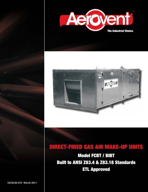
® The Industrial Choice. DIRECT-FIRED GAS AIR MAKE-UP UNITS Model FCBT / BIBT Built to ANSI Z83.4 & Z83.18 Standards ETL Approved CATALOG 872 March 2011
- Page 2 and 3: Introduction What is make-up air Ma
- Page 4 and 5: Construction Features The BT series
- Page 6 and 7: Standard Temperature Controls Two s
- Page 8 and 9: Sequence of Operation - Gas Burner
- Page 10 and 11: Performance Data Model FCBT Forward
- Page 12 and 13: Single Fan Model FCBT - Size 110-12
- Page 14 and 15: Single Fan Model FCBT - Size 127-13
- Page 16 and 17: Single Fan Model BIBT Direct-Fired
- Page 18 and 19: Accessories - Single Fan Assemblies
- Page 20 and 21: Twin Fan Model FCBT-DW Direct-Fired
- Page 22 and 23: Accessories - Twin Fan Assemblies V
- Page 24 and 25: Pressure Drop Curves for Accessorie
- Page 26 and 27: Pressure Drop Curves for Accessorie
- Page 28: PROPELLER FANS | TUBEAXIAL & VANEAX
®<br />
The Industrial Choice.<br />
DIRECT-FIRED GAS AIR MAKE-UP UNITS<br />
Model <strong>FCBT</strong> / <strong>BIBT</strong><br />
Built to ANSI Z83.4 & Z83.18 Standards<br />
ETL Approved<br />
CATALOG 872 March 2011
Introduction<br />
What is make-up air<br />
<strong>Make</strong>-up air is outside air tempered and introduced<br />
into a building to eliminate negative pressure and<br />
provide a positive operating pressure within a facility.<br />
Why do you need make-up air<br />
Fans and blowers used in spray booths, hoods,<br />
ovens, dust collectors, ventilators, and other plant<br />
equipment exhaust air to the outside. Without a controlled<br />
introduction of “make-up” air an air-starved<br />
environment will result.<br />
When do you know you need make-up air<br />
<strong>Make</strong>-up air is required when:<br />
• Gravity stacks from unit heaters and processes<br />
backvent.<br />
• Exhaust systems do not perform at rated volume<br />
leading to poor control of contaminants.<br />
• The perimeter of the building is cold due to a high<br />
infiltration rate.<br />
• There are several indrafts at exterior doors, windows,<br />
and building openings.<br />
• Exterior doors are hard to open.<br />
• Heating systems are not able to maintain uniform<br />
comfort conditions throughout the building. The<br />
outer core area is cold due to infiltration while the<br />
center core is overheated.<br />
How much does make-up air cost<br />
<strong>Make</strong>-up air doesn’t cost money. It actually saves<br />
money by:<br />
• Extending the life of heat exchangers on combustion<br />
equipment.<br />
• Providing more uniform temperatures throughout<br />
the building, reducing overheated areas and cold<br />
drafty areas.<br />
• Allowing exhaust systems to operate at designed<br />
capacity, reducing the need for additional equipment.<br />
• Minimizing the damage to materials from contaminates<br />
which may exist in the the local atmosphere.<br />
• Reducing employee turnover and absenteeism<br />
because of better health conditions and plant<br />
cleanliness.<br />
• Improving products with fewer rejects because<br />
furnaces operate at designed conditions.<br />
How much make-up air do you need<br />
The recommended procedure to determine the<br />
amount of make-up air needed is to total the CFM<br />
capacity of all the exhaust fans and blowers in the<br />
plant and add 10% to create a positive pressure<br />
situation.<br />
If the data is not available, the following equations<br />
can be used as a means of determining how much<br />
make-up air is required.<br />
Paint Spray Booth: 125 to 175 CFM per square foot<br />
of face opening.<br />
Oven Exhaust: One air change per minute of oven<br />
volume in cubic feet.<br />
Fume Exhaust: CFM = area of discharge pipe in<br />
square feet x velocity (3,000 fpm average).<br />
Roof Ventilator: CFM = area of discharge pipe in<br />
square feet x velocity (3,000 fpm average).<br />
Dust Collector: Area of discharge pipe in square feet<br />
x velocity (4,000 fpm average).<br />
Canopy Hoods: 100 to 300 CFM per square foot of<br />
hood open area.<br />
Combustion <strong>Air</strong> For Furnaces: CFM = fuel consumed<br />
in Btu per hour divided by 6,000.<br />
Drying, Baking, or Curing Ovens: 100 CFM per<br />
square foot of both cross sections.<br />
Pickling or Cleaning Tanks: 150 CFM per square foot<br />
of door opening or 200 CFM per square foot of hood<br />
face opening.<br />
Contents<br />
Introduction.........................2<br />
Application Considerations................3<br />
Construction Features ..................4<br />
Accessories.........................5<br />
Standard Temperature Controls.............6<br />
Control Panel .......................7<br />
Pipetrain ..........................7<br />
Sequence of Operation – <strong>Gas</strong> Burner.........8<br />
Typical Specifications...................9<br />
Performance Data – Forward Curved ........ 10<br />
Performance Data – Backward Inclined....... 11<br />
Dimensional Data .................. 12-23<br />
Pressure Drop Curves for Accessories ..... 24-27<br />
©2004 <strong>Aerovent</strong>, Twin City Fan Companies, Ltd.<br />
Catalog illustrations cover the general appearance of products at the time of publication<br />
and we reserve the right to make changes in design and construction at any time without notice.<br />
2 <strong>Aerovent</strong> Catalog 872
Application Considerations<br />
<strong>Air</strong> Balance<br />
Exhaust fans cannot work properly without an adequate supply of air. If provision for air supply is not made,<br />
the vacuum created reduces the effectiveness of mechanical ventilation. Negative pressure also causes excessive<br />
infiltration, making it difficult to heat properly. These conditions can be corrected by replacing the exhausted<br />
air with clean, fresh, pretreated air. The primary purpose of make-up air is to temper outside air and supply it<br />
in sufficient quantities to bring about the condition of balanced ventilation.<br />
Depending upon the quantity of make-up air in relation to the exhaust, the heating system will shut down<br />
during the working day allowing the make-up air system to handle the entire load. The heating system then<br />
functions only to maintain satisfactory temperatures at nighttime and other plant shutdown periods.<br />
When you add an air make-up system to an existing plant it is necessary to make a detailed analysis of<br />
the overall situation in order to determine what the relationship might be between the heat added by make-up<br />
air and that supplied from the plant heating system. Where exhaust systems already exist, the installation of<br />
make-up air usually will not increase the heating load and can bring about a reduction of overall heating costs.<br />
This may be understood by considering that infiltrated air, warmed at least partially by the plant heating system,<br />
is ultimately mixed with room air and exhausted through the ventilating fans. Infiltration of unheated air results<br />
in a decline of heating efficiency. Most heating systems are not adequately rated to cope with infiltration when<br />
appreciable negative pressures exist. <strong>Air</strong> make-up units provide a systematic method of heating entering air<br />
and supplying it in controlled quantity. With the proper balance of supply and exhaust, infiltration is eliminated<br />
and negative pressures are equalized. By properly tempering supply air, the heating system is relieved of this<br />
abnormal load. The results are uniform space heating, effective ventilation, and improved comfort.<br />
Heating<br />
Experience with fresh air heating systems has shown that<br />
it is practical and economically sound to heat industrial<br />
plants and even warehouses with fresh air. The question<br />
of whether to use 100% fresh air or recirculate some portion<br />
is debatable, and engineers are using both methods<br />
in their applications.<br />
When direct-fired systems were first used some authorities<br />
felt that positive exhaust was necessary to assure a<br />
balance and prevent the possibility of products of combustion<br />
buildup. It is now generally recognized that air<br />
can be supplied into most buildings having no mechanical<br />
exhaust and in quantities sufficient to heat them without<br />
building up a positive pressure of more than a few<br />
hundredths of an inch water gauge. It is the reverse of<br />
infiltration and this principle can be used to design fresh<br />
air plant heating.<br />
The standard air make-up unit is used for industrial<br />
space heating with 100% outside air or with a fixed percentage of recirculation, and in some designs with a<br />
combination of these. Your <strong>Aerovent</strong> representative can assist you in determining application requirements for<br />
general air make-up and for fresh air heating. They can supply detailed information as it may apply to specific<br />
conditions.<br />
®<br />
3 <strong>Aerovent</strong> Catalog 872
Construction Features<br />
The BT series direct-fired gas air make-up unit is a complete air supply system in a self-contained package with<br />
fan, burner, and controls. The unit is ready for connection to the gas line and power source. These systems<br />
are for use in industrial or commercial applications where supplying tempered outside air is required.<br />
Standard Features<br />
• Heavy duty forward curved or backward inclined<br />
DWDI centrifugal blower with pillow block bearings<br />
• ANSI and FM approved gas manifold design<br />
• Heavy duty 14 gauge steel housing<br />
• Enamel paint<br />
• Large access door for internal accessibility<br />
• Lifting eyes for ease of unit installation<br />
• Venturi monitored airflow supervision<br />
• 0 to 92 degree temperature rise<br />
• 120 volt fused control circuit with 230/460 to 120<br />
volt control transformer<br />
• Number-coded wires and terminal strips<br />
• Dual fuel burner (Maxon)<br />
• Factory assembled and tested<br />
• Weatherproof control enclosure<br />
• Remote operating station<br />
• Unit support/mounting channels<br />
• Maxitrol Series 14 temperature control<br />
• Honeywell series 7800 flame safeguard protection<br />
• Flame rod<br />
• Safety shutoff valves<br />
• Discharge temperature sensor<br />
• Drives rated for 150% of motor nameplate rating<br />
• High temperature limit<br />
• Single point gas and electrical connections<br />
• Non-recycle system with low fire start protection<br />
with main flame supervision<br />
• 25:1 temperature control modulation<br />
• Pilot gas pressure regulator<br />
• High and low gas pressure switch<br />
4 <strong>Aerovent</strong> Catalog 872
Accessories<br />
80/20 Recirculating<br />
The 80/20 recirculating system allows 80% recirculation<br />
and is designed to insure that a minimum of<br />
20% of the designed performance is outside air.<br />
Recirculated air is not allowed to flow across the<br />
burner. Manual setpoint is standard. Room pressure<br />
control available as an option.<br />
V-Bank Filter Section<br />
The standard filter is a 2" Farr 30/30 disposable type<br />
with washable as an option.<br />
MODULATING<br />
PROFILE<br />
BURNER<br />
RETURN AIR<br />
DAMPER<br />
Additional Options<br />
• V-bank filter section<br />
• Intake hood with bird screen<br />
• 90 degree discharge elbow<br />
• Roof curb<br />
• Curb mount construction<br />
• Inlet bird screen<br />
• Modulating room temperature control (Maxitrol<br />
Series 44)<br />
• IRI pipe train manifolds<br />
• <strong>Direct</strong>ional discharge grille, single and double<br />
deflection<br />
• Circuit analyzer<br />
• Insulated construction<br />
• Vertical support stand<br />
• Two speed operation<br />
• UV flame scanner<br />
• Mild weather thermostat<br />
• Service platform<br />
• Main gas regulator<br />
• Vibration isolators (unit mount)<br />
• Tamper proof remote station<br />
• Reset module<br />
• Disconnect switch<br />
• OSHA Belt guard<br />
• Motor operated damper (inlet or discharge)<br />
• Freeze protection thermostat<br />
• Door switch interlock<br />
• Painted unit and accessories<br />
• Extended grease lines<br />
®<br />
5 <strong>Aerovent</strong> Catalog 872
Standard Temperature Controls<br />
Two standard systems<br />
for temperature control<br />
are available offering<br />
a choice of functions<br />
for the regulation<br />
of air temperature.<br />
The outlet temperature<br />
control (OTC) system<br />
senses only the discharge<br />
air temperature<br />
at the unit. The sensing<br />
device is located in the<br />
airstream. It averages<br />
the temperature and<br />
sends a signal to the<br />
servomechanism in the<br />
Tamper-proof<br />
control system<br />
modulating regulator. The regulator in turn modulates<br />
the gas pressure in the burner manifold, and the gas<br />
flow is varied to maintain the air temperature constant<br />
at the sensor. The OTC system is used where the<br />
volume of air supplied is relatively small compared to<br />
the volume of the building, which usually means that<br />
it is not intended for the air make-up unit to pick up<br />
an appreciable part of the building heating.<br />
In most installations, room temperature control is<br />
desirable. Two controllers are available for this operation.<br />
The simplest and least expensive control is a<br />
thermostat added to the OTC system (OTC-RO) and<br />
located to sense the room temperature. The contacts<br />
close on a call for heat and cause an increase in<br />
the discharge air temperature. The air make-up unit<br />
delivers air at the higher temperature until the room<br />
thermostat is satisfied; full control is then returned<br />
to the discharge sensor. The limited amount of temperature<br />
increase eliminates excessive discharge air<br />
temperature. The temperature setting is usually 5°<br />
below the outlet temperature set point.<br />
The modulating room temperature control (MRTC)<br />
is slightly more sophisticated. Instead of a thermostat,<br />
a thermistor is used to sense the room temperature.<br />
The signal actuates the modulating regulator<br />
to provide an incremental increase or decrease of<br />
the discharge temperature, providing closer control<br />
and preventing an abrupt change in the temperature<br />
of the air at the outlet of the unit or outlets of a<br />
distribution system. In the room temperature control<br />
system the discharge air temperature sensor performs<br />
a limiting function so that the discharge air cannot<br />
exceed a reasonable temperature. The discharge air<br />
temperature can be set to suit the individual requirements<br />
at the time of installation.<br />
The air temperature controllers are combined with<br />
the operation selector switch and indicator lights–all<br />
mounted in a remote operating station. The OTC<br />
unit can be mounted in any convenient location and<br />
contains a summer-off-winter selector switch and<br />
indicator lamps showing that power is on, the fan is<br />
running, and there is a flame on the burner. There is<br />
also a knob for setting the discharge temperature of<br />
the air make-up unit.<br />
The OTC-RO control station contains all of these<br />
controls and indicators in addition to a room temperature<br />
thermostat. The MRTC remote operating<br />
station has a thermistor on top instead of the on-off<br />
thermostat. The OTC-RO or MRTC remote operating<br />
stations should be mounted in a location where the<br />
desired room temperature is best sensed. This will be<br />
a matter of judgment, made at the time of installation.<br />
The circuit design can include an optional mild<br />
weather thermostat. This thermostat senses the outside<br />
temperature and, at a predetermined setting,<br />
will cause the burner to be shut off completely while<br />
allowing the fan to run. This makes it possible to<br />
have year-round operation with the selector switch<br />
set to the winter position and the mild weather<br />
thermostat set to a desirable “heat off” temperature<br />
(65°F). When the outside temperature is above 65°<br />
the heat will be off. When it is below 65° the burner<br />
will be in operation and the temperature regulated<br />
according to the modulating control.<br />
Outlet Temperature Control (OTC)<br />
Modulating Room Temperature Control (MRTC)<br />
6 <strong>Aerovent</strong> Catalog 872
Control Panel<br />
The main control panel is designed with the service<br />
technician in mind. The panel is licensed to carry the<br />
UL label under the 508 listing. The panel meets all<br />
standards of the National Electric Code and includes<br />
as standard:<br />
• Step-down control transformer<br />
• Motor starter with overloads<br />
• Ignition transformer<br />
• Honeywell 7800 series primary flame safe-guard<br />
system<br />
• Maxitrol temperature controller<br />
• Purge and reset timers<br />
The incorporation of the Honeywell series 7800 flame<br />
relay offers the customer the following options:<br />
• Remote relay reset (reset lockout from remote<br />
panel)Fault history (readout of six most recent<br />
faults from LED readout for troubleshooting flame<br />
failures)<br />
Pipetrain<br />
Liquid-tight conduit is used for all interconnecting<br />
wiring. Piping is in accordance with ANSI standard<br />
along with IRI and FM.<br />
• Motorized safety shutoff valve<br />
• Blocking valve<br />
• Pilot solenoid<br />
• High/Low gas pressure switch<br />
• Pilot regulator<br />
• Manual pilot shutoff valve<br />
• Maxitrol MR 212 modulating valve<br />
• Vent valve as required by IRI<br />
• Adjustable pilot orifice<br />
7 <strong>Aerovent</strong> Catalog 872
Sequence of Operation – <strong>Gas</strong> Burner<br />
Remote Station Selector Switch starts and stops all unit functions. In “winter” position, operates<br />
fan and burner control system in proper sequence. In “summer” position, operates fan only. Serves<br />
also as manual reset.<br />
Remote Station Indicator Lamp shows when selector is in either operating position.<br />
Mild Weather Thermostat causes unit to automatically shift from winter to summer, whichever is<br />
required, according to outside temperature (adjustable) (optional).<br />
Reset Timer allows timed bypass of the freeze protection thermostat, permitting unit to start when<br />
the temperature is below the set point of the freeze protection thermostat (optional with low limit).<br />
Freeze Protection Thermostat causes complete unit shutdown if discharge air temperature falls<br />
dangerously low (optional).<br />
Stop Relay causes complete unit shutdown in the event of any malfunction in the flame safety or<br />
fan starter circuit (optional with low limit).<br />
Damper Motor opens damper when selector switch is turned on (optional).<br />
Damper End Switch starts the fan when damper reaches open position (optional).<br />
Fan Starter provides fan motor protection station, shows damper open and fan on.<br />
Fan On Indicator at remote operating station, shows damper open and fan on.<br />
Purge Timer provides 7-second prepurge time.<br />
Low <strong>Gas</strong> Pressure Switch causes shutdown in event of insufficient gas pressure. (Manual reset on<br />
the switch.)<br />
High <strong>Gas</strong> Pressure Switch causes shutdown in event of excessive gas pressure. (Manual reset on<br />
the switch.)<br />
<strong>Air</strong>flow Switch senses air velocity pressure and will cause complete unit shutdown if airflow drops<br />
below requirement for satisfactory combustion.<br />
High Limit Thermostat causes complete shutdown if discharge air temperature exceeds set point.<br />
(Manual reset on the switch.)<br />
Combustion Safeguard Relay controls ignition, pilot and safety shut-off valve. Supervises main flame,<br />
closes SSOV instantly upon power or flame failure, causes complete shutdown in case of unproven pilot<br />
or flame failure after ignition of the main flame. (Optional remote manual reset from operating station.)<br />
Indicator Lamp at remote station, shows burner on.<br />
Low Fire Start integral with modulating valve.<br />
Modulator/Regulator Valve<br />
FULLY MODULATING TEMPERATURE CONTROL SYSTEMS<br />
A Outlet Temperature Control System (OTC) holds constant outlet temperature adjustable at the<br />
remote operating station and has outdoor temperature compensation.<br />
Discharge <strong>Air</strong> Temperature Thermostat actuates the modulating regulator to hold average outlet temperature<br />
to control point. Remotely adjustable.<br />
B Outlet Control System with room override (OTC-RO) (optional) maintains room temperature to<br />
remote thermostat setting and is discharge temperature compensated. Primarily used for morning<br />
warmup or when overhead doors open.<br />
Room Thermostat resets the discharge air thermostat according to room requirements holding the<br />
room temperature to the control point. (Adjustable)<br />
Discharge <strong>Air</strong> Temperature Thermostat automatically limits extreme changes in discharge temperature.<br />
(Adjustable)<br />
C Modulated Room Temperature Control (MRTC) (optional) maintains room temperature within very<br />
narrow limits, provides extreme accuracy and rapid response to small temperature changes.<br />
8 <strong>Aerovent</strong> Catalog 872
Typical Specifications<br />
<strong>Models</strong> <strong>FCBT</strong> forward curved and <strong>Models</strong> <strong>BIBT</strong> backward inclined direct-fired gas centrifugal DW air make-up<br />
units shall be manufactured by <strong>Aerovent</strong>, Minneapolis, Minnesota and shall be of the size and capacity as<br />
indicated on drawings and schedules.<br />
WHEEL — Wheels shall be double width with forward curved blades or backward inclined blades. The forward<br />
curved wheels feature die-formed blades assembled in heavy end rings and center plate. Wheels shall be statically<br />
and dynamically balanced and furnished with straight bore hubs.<br />
HOUSING — Housings shall be of 14 gauge steel, of modular construction where sections are mechanically<br />
fastened. Housings shall be equipped with a visual burner inspection port, access door, lifting eyes, and unit<br />
support frame for mounting.<br />
GAS PIPETRAIN — Pipetrain shall consist of SSOV valve, pilot valve, vent valve (IRI only), blocking valve, highlow<br />
gas pressure switches with manual resets, heavy duty plug cocks, pressure gauge and modulating regulator<br />
out of the airstream. Piping shall conform to FM or IRI standards. Please specify when ordering.<br />
. .............. . ......<br />
CONTROL CABINET — A control cabinet shall house the fan motor magnetic starter with manual reset overload<br />
relays, control transformer, Honeywell solid-state flame sensing relay, non-recycle timer, fuse and terminal<br />
strips. Unit shall include a remote control station with summer-winter-off selection switch, power on, fan on,<br />
burner on lights, and discharge temperature selector. The temperature control system shall be of solid-state<br />
design manufactured by the Maxitrol Company to modulate the burner in accordance with the remote control<br />
station setting. All controls on the unit are to be wired to the respective points in the cabinet with liquid-tight<br />
conduit and in accordance with the National Electric Code. The unit shall also include high temperature limit,<br />
airflow switch, and positive low fire start.<br />
. . . .....<br />
FLAME DETECTOR — A flam rod flame detector shall be incorporated into the unit to supervise both the pilot<br />
and main burner flame.<br />
. . .<br />
BURNER — The burner is a Maxon with 25:1 turndown ratio. The manifold body is heavy duty cast iron, fully<br />
treated for rust resistance. The mixing plates are type 430 stainless steel.<br />
UNITS SHALL COME COMPLETE WITH:<br />
• V-Bank Filter Cabinet<br />
• Roof Curb<br />
• Inlet Hood with Vanes<br />
• Mild Weather Control<br />
• Inlet Hood less Vanes<br />
• Freeze Protection Thermostat<br />
• 90 Degree Discharge Elbow • Inlet Bird Screen<br />
• Filtered Inlet Hood<br />
• Circuit Analyzer<br />
• <strong>Direct</strong>ional Discharge Grille • OSHA Belt Guard<br />
• Vibration Isolators<br />
• Reset Module<br />
• Tamperproof Control Station • Service Platform<br />
• Push-to-Test Lights<br />
• Insulated Construction<br />
• Curb Mounting<br />
• UV Flame Detection<br />
• Digital Temperature Controls<br />
• Door Switch Interlock<br />
• Vertical Support Stand<br />
• Two Speed Operation<br />
• Main <strong>Gas</strong> Regulator<br />
• Disconnect Switch<br />
• Extended Grease Lines<br />
• Modulating Room Temperature<br />
Controls<br />
TESTING — Unit(s) shall be guaranteed by the manufacturer to deliver at the rated performance levels. Unit(s)<br />
shall be completely packaged and test fired at the factory before shipment.<br />
®<br />
9 <strong>Aerovent</strong> Catalog 872
Performance Data<br />
Model <strong>FCBT</strong> Forward Curved Centrifugal DW<br />
<strong>Direct</strong>-<strong>Fired</strong> <strong>Gas</strong> <strong>Air</strong> <strong>Make</strong>-<strong>Up</strong> <strong>Units</strong><br />
Catalog Numbering System<br />
Assign catalog number by using the numbering system<br />
outlined in the example at right. Fan type, fan<br />
size, RPM, and HP are found in the rating tables.<br />
Definitions<br />
Btu/Hr is sensible heat release. To determine cfh gas<br />
input, divide Btu by the net heat value of the fuel.<br />
CFM is net volume at discharge at 70°F.<br />
External Static Pressure is pressure available for<br />
addition of ducts.<br />
Forward Curved<br />
DW <strong>Air</strong> <strong>Make</strong>-<strong>Up</strong><br />
Fan Size<br />
Fan RPM<br />
Motor HP<br />
<strong>FCBT</strong> - 118 - 943 - 7 1 /2<br />
AMU<br />
MODEL<br />
FAN<br />
MODEL<br />
CFM<br />
OUT-<br />
LET<br />
VE-<br />
LOC-<br />
ITY<br />
BTU/<br />
HR<br />
ISP<br />
EXTERNAL STATIC PRESSURE<br />
1/4" 1/2"H 3/4" 1" 1 1/4" 1 1/2" 1 3/4" 2"<br />
RPM BHP RPM BHP RPM BHP RPM BHP RPM BHP RPM BHP RPM BHP RPM BHP<br />
<strong>FCBT</strong> 110 VFC 16 4000 1446 0.875 666 1.25 740 1.53 808 1.83 869 2.12 928 2.43 984 2.73 1038 3.04 1089 3.35<br />
<strong>FCBT</strong> 115 VFC 16 5000 1807 0.875 665 1.62 735 1.94 800 2.26 862 2.61 920 2.96 975 3.32 1027 3.7 1076 4.07<br />
<strong>FCBT</strong> 115 VFC 16 6000 2168 0.875 675 2.14 739 2.47 799 2.81 858 3.19 914 3.57 967 3.96 1019 4.37 1069 4.8<br />
<strong>FCBT</strong> 118 VFC 18 7500 2152 0.875 622 2.62 672 2.97 721 3.36 767 3.74 812 4.15 857 4.59 902 5.05 948 5.56<br />
<strong>FCBT</strong> 120 VFC 20 10000 2283 0.875 571 3.72 615 4.19 657 4.67 698 5.18 737 5.71 774 6.23 812 6.81 849 7.39<br />
<strong>FCBT</strong> 122 VFC 22 12500 2271 0.875 510 4.65 549 5.22 587 5.84 623 6.46 658 7.12 692 7.8 725 8.49 759 9.26<br />
<strong>FCBT</strong> 127 VFC 28 15000 1728 0.875 391 5.08 430 6.02 467 7.02 501 8.01 532 8.97 562 9.97 590 10.95 619 12.04<br />
<strong>FCBT</strong> 127 VFC 28 17500 2016 0.875 400 6.49 435 7.44 469 8.47 502 9.57 534 10.73 564 11.89 592 13.02 619 14.18<br />
<strong>FCBT</strong> 130A VFC 28 20000 2304 0.875 412 8.27 445 9.27 476 10.32 507 11.49 536 12.63 566 13.95 594 15.24 621 16.55<br />
<strong>FCBT</strong> 130A VFC 28 22500 2592 0.875 427 10.41 457 11.51 487 12.64 516 13.86 543 15.04 570 16.32 597 17.7 623 19.09<br />
<strong>FCBT</strong> 130B VFC 32 25000 2290 0.875 365 9.52 391 10.63 417 11.88 442 13.18 467 14.66 491 16.2 514 17.74 537 19.35<br />
<strong>FCBT</strong> 130B VFC 32 30000 2749 0.875 391 13.86 415 15.13 438 16.43 460 17.76 482 19.23 503 20.69 524 22.27 545 23.99<br />
<strong>FCBT</strong> 136 VFC 36 35000 2547 0.875 336 14.72 358 16.18 380 17.86 401 19.57 421 21.3 441 23.19 461 25.28 480 27.38<br />
<strong>FCBT</strong> 136 VFC 36 40000 2910 0.875 355 19.5 376 21.27 396 22.97 416 24.87 435 26.87 453 28.64 471 30.65 489 32.8<br />
<strong>FCBT</strong> 140 VFC 40 50000 2894 0.875 322 24.87 341 27.15 358 29.07 376 31.45 393 33.82 409 36.11 425 38.58 441 41.21<br />
<strong>FCBT</strong> 222 VFC-2 22 25000 2271 0.875 536 10.02 577 11.26 616 12.53 654 13.88 691 15.32 726 16.73 761 18.24 796 19.84<br />
<strong>FCBT</strong> 222 VFC-2 22 30000 2726 0.875 569 14.32 607 15.8 643 17.26 678 18.8 711 20.29 744 21.9 776 23.54 806 25.13<br />
<strong>FCBT</strong> 225 VFC-2 25 35000 2534 0.875 491 15.33 527 17.14 560 18.87 592 20.66 623 22.51 653 24.42 682 26.37 711 28.46<br />
<strong>FCBT</strong> 227 VFC-2 28 40000 2304 0.875 432 17.7 467 19.91 500 22.21 532 24.66 563 27.19 594 29.95 624 32.81 653 35.73<br />
<strong>FCBT</strong> 227 VFC-2 28 45000 2592 0.875 448 22.32 480 24.76 512 27.29 542 29.83 571 32.48 599 35.18 626 37.9 654 41.01<br />
<strong>FCBT</strong> 230 VFC-2 28 50000 2880 0.875 467 27.72 497 30.62 525 33.19 554 35.96 582 33.77 608 41.49 634 44.44 660 47.59<br />
<strong>FCBT</strong> 230 VFC-2 28 55000 3168 0.875 491 34.48 515 37.03 542 40.14 568 43.11 594 46.03 620 49.07 645 52.16 669 55.26<br />
<strong>FCBT</strong> 233 VFC-2 32 60000 2749 0.875 410 29.69 435 32.36 460 35.34 483 38.19 506 41.32 529 44.7 551 48.08 572 51.5<br />
<strong>FCBT</strong> 233 VFC-2 32 65000 2978 0.875 425 35.28 450 38.57 473 41.47 495 44.39 517 47.64 538 50.86 559 54.33 580 58.03<br />
<strong>FCBT</strong> 236 VFC-2 36 70000 2547 0.875 353 31.7 376 34.82 399 38.4 421 42.07 442 45.77 463 49.84 484 54.34<br />
<strong>FCBT</strong> 236 VFC-2 36 75000 2728 0.875 363 36.7 385 39.92 407 43.55 428 47.28 449 51.35 469 55.41 489 59.79<br />
<strong>FCBT</strong> 240 VFC-2 40 100000 2894 0.875 338 53.43 358 58.35 376 62.54 395 67.73 412 72.37 429 77.4 446 82.81<br />
Performance ratings of the base units include the effects of appurtenances in the airstream (i.e. burner section).<br />
Performance ratings do not include the effects of optional accessories in the airstream (i.e. filter cabinet). See pages 24-27 for pressure losses.<br />
Power rating (bhp) does not include drive losses.<br />
Performance ratings are based on units with ducted discharge... . . . .<br />
10 <strong>Aerovent</strong> Catalog 872
Performance Data<br />
Model <strong>BIBT</strong> Backward Inclined Centrifugal DW<br />
<strong>Direct</strong>-<strong>Fired</strong> <strong>Gas</strong> <strong>Air</strong> <strong>Make</strong>-<strong>Up</strong> <strong>Units</strong><br />
Catalog Numbering System<br />
Assign catalog number by using the numbering system<br />
outlined in the example at right. Fan type, fan<br />
size, RPM, and HP are found in the rating tables.<br />
Definitions<br />
Btu/Hr is sensible heat release. To determine cfh gas<br />
input, divide Btu by the net heat value of the fuel.<br />
CFM is net volume at discharge at 70°F.<br />
External Static Pressure is pressure available for<br />
addition of ducts.<br />
Backward Inclined<br />
DW <strong>Air</strong> <strong>Make</strong>-<strong>Up</strong><br />
Fan Size<br />
Fan RPM<br />
Motor HP<br />
<strong>BIBT</strong> - 116 - 2179 - 5<br />
AMU<br />
MODEL<br />
FAN<br />
MODEL<br />
CFM<br />
OUT-<br />
LET<br />
VE-<br />
LOC-<br />
ITY<br />
BTU/<br />
HR<br />
ISP<br />
EXTERNAL STATIC PRESSURE<br />
1/4" 1/2"H 3/4" 1" 1 1/4" 1 1/2" 1 3/4" 2"<br />
RPM BHP RPM BHP RPM BHP RPM BHP RPM BHP RPM BHP RPM BHP RPM BHP<br />
<strong>BIBT</strong> 116 VBC 16 4000 1446 0.875 1247 1.12 1319 1.31 1387 1.5 1453 1.7 1514 1.9 1574 2.1 1632 2.31 1691 2.52<br />
<strong>BIBT</strong> 116 VBC 16 5000 1807 0.875 1399 1.61 1464 1.83 1527 2.06 1586 2.29 1643 2.53 1699 2.77 1753 3.02 1805 3.26<br />
<strong>BIBT</strong> 116 VBC 16 6000 2168 0.875 1566 2.27 1624 2.52 1680 2.78 1735 3.05 1788 3.32 1839 3.59 1889 3.88 1937 4.16<br />
<strong>BIBT</strong> 116 VBC 16 7500 2711 0.875 1836 3.86 1884 3.97 1932 4.27 1979 4.57 2025 4.89 2071 5.22 2115 5.54 2159 5.88<br />
<strong>BIBT</strong> 122 VBC 22 10000 1817 0.875 1005 3.25 1051 3.69 1095 4.15 1137 4.61 1178 5.09 1217 5.57 1255 6.05 1292 6.55<br />
<strong>BIBT</strong> 122 VBC 22 13000 2362 0.875 1190 5.45 1228 5.97 1266 6.52 1302 7.07 1338 7.64 1373 8.23 1408 8.84 1441 9.43<br />
<strong>BIBT</strong> 125 VBC 25 15000 2143 0.875 1009 5.81 1040 6.34 1072 6.92 1104 7.53 1136 8.17 1167 8.82 1197 9.46 1227 10.12<br />
<strong>BIBT</strong> 125 VBC 25 18000 2571 0.875 1157 8.77 1184 9.41 1211 10.05 1237 10.68 1264 11.37 1290 12.06 1317 12.8 1343 13.54<br />
<strong>BIBT</strong> 128 VBC 28 19500 2247 0.875 917 7.82 944 8.51 972 9.26 999 10.02 1027 10.84 1054 11.67 1080 12.49 1106 13.34<br />
<strong>BIBT</strong> 128 VBC 28 22000 2535 0.875 1004 10.27 1029 11.06 1053 11.82 1077 12.62 1102 13.48 1126 14.34 1151 15.26 1175 16.2<br />
<strong>BIBT</strong> 132 VBC 32 25000 2290 0.875 830 10.28 854 11.75 878 12.09 902 13.07 926 14.1 950 15.16 973 16.22 996 17.3<br />
<strong>BIBT</strong> 132 VBC 32 29500 2703 0.875 942 15.02 963 16.06 984 17.12 1004 18.15 1024 19.21 1045 20.37 1065 21.52 1086 22.76<br />
<strong>BIBT</strong> 136 VBC 36 34000 2474 0.875 784 15.39 804 16.58 824 17.81 844 19.08 864 20.42 884 21.81 903 23.17 923 24.66<br />
<strong>BIBT</strong> 136 VBC 36 40000 2910 0.875 892 22.59 910 24.05 927 25.44 944 26.85 961 28.28 978 29.74 995 31.26 1012 32.83<br />
<strong>BIBT</strong> 140 VBC 40 50000 2894 0.875 797 28.2 813 30.03 828 31.74 844 33.59 859 35.35 874 37.16 889 39.03 904 40.96<br />
<strong>BIBT</strong> 222 VBC-2 22 25000 2271 0.875 1216 10.79 1257 11.87 1298 13.02 1337 14.18 1413 16.61 1450 17.86 1485 19.1<br />
<strong>BIBT</strong> 222 VBC-2 22 30000 2726 0.875 1424 17.37 1460 18.67 1494 19.94 1528 21.29 1562 22.69 1595 24.1 1627 25.51<br />
<strong>BIBT</strong> 225 VBC-2 25 35000 2500 0.875 1189 17.69 1218 19.01 1246 20.31 1275 21.7 1303 23.11 1332 24.62 1361 26.19 1389 27.76<br />
<strong>BIBT</strong> 228 VBC-2 28 40000 2304 0.875 981 17.79 1009 19.31 1037 20.89 1065 22.57 1093 24.31 1121 26.13 1149 28.01 1176 29.88<br />
<strong>BIBT</strong> 228 VBC-2 28 45000 2592 0.875 1073 23.28 1098 24.95 1123 26.65 1148 28.4 1173 30.22 1198 32.12 1224 34.17 1248 36.11<br />
<strong>BIBT</strong> 228 VBC-2 28 50000 2880 0.875 1167 29.87 1191 31.84 1214 33.73 1236 35.57 1259 37.52 1281 39.44 1304 41.52 1326 43.57<br />
<strong>BIBT</strong> 228 VBC-2 28 55000 3168 0.875 1263 37.71 1285 39.89 1307 42.07 1328 44.16 1348 46.17 1369 48.3 1389 50.37<br />
<strong>BIBT</strong> 232 VBC-2 32 60000 2749 0.875 1003 33.65 1024 35.87 1046 38.21 1067 40.48 1088 42.82 1109 45.25 1130 47.77 1151 50.37<br />
<strong>BIBT</strong> 232 VBC-2 32 65000 2978 0.875 1070 40.73 1091 43.33 1111 45.81 1130 48.18 1150 50.71 1169 53.17 1189 55.83<br />
<strong>BIBT</strong> 236 VBC-2 36 70000 2547 0.875 842 35.41 863 38.11 883 40.74 903 43.46 923 46.29 944 49.4 964 52.46 984 55.62<br />
<strong>BIBT</strong> 236 VBC-2 36 75000 2728 0.875 889 41.62 909 44.56 928 47.38 947 50.25 965 53.05 984 56.12<br />
<strong>BIBT</strong> 240 VBC-2 40 100000 2894 0.875 837 60.67 854 64.64 870 68.39 886 72.17<br />
Performance ratings of the base units include the effects of appurtenances in the airstream (i.e. burner<br />
section).<br />
Performance ratings do not include the effects of optional accessories in the airstream (i.e. filter cabinet).<br />
See pages 24-27 for pressure losses.<br />
Power rating (bhp) does not include drive losses.<br />
Performance ratings are based on units with ducted discharge.<br />
®<br />
11 <strong>Aerovent</strong> Catalog 872
Single Fan Model <strong>FCBT</strong> – Size 110-122<br />
<strong>Direct</strong>-<strong>Fired</strong> <strong>Gas</strong> <strong>Air</strong> <strong>Make</strong>-up Unit<br />
Horizontal Configuration - 100% Outside <strong>Air</strong><br />
1 3 /4<br />
B<br />
1 3 /4.INLET.FLANGE<br />
1 3 /4<br />
F<br />
9*<br />
D*<br />
2<br />
31<br />
CONTROL.ROOM<br />
31.WIDE.x.10.DEEP<br />
L<br />
9*<br />
50<br />
PIPING.ROOM<br />
50.WIDE.x.18.DEEP<br />
1 3 /4<br />
J<br />
R<br />
D*<br />
1<br />
G<br />
H<br />
H<br />
3 1 /8<br />
1 3 /4<br />
A<br />
P<br />
B<br />
L<br />
D*<br />
3 1 /8<br />
1<br />
10.GA..CURB.CHANNEL<br />
CURB.CHANNEL.DETAIL<br />
18<br />
10<br />
3<br />
9*<br />
FAN.DOOR<br />
OPP.SIDE<br />
28H.x.37W<br />
E<br />
3<br />
D<br />
1 3 /4<br />
PIPING.DOOR<br />
28H.x.37W<br />
ELECTRICAL.ROOM<br />
32H.x.28W<br />
MOTOR<br />
NOTES:<br />
1. * Designates damper dimension when ordered.<br />
2. Pipe train size varies with unit.<br />
3. Birdscreen is optional.<br />
4. 16 gauge housing.<br />
5. Discharge position: 1 FRONT 2 UP 3 DOWN<br />
6. D = Damper dimension when ordered and flange on down discharge.<br />
7. P and R = Discharge opening when damper is not ordered.<br />
8. Damper is shipped loose on down discharge units.<br />
SIZE A B D E F G H J L P R<br />
APPROX.<br />
WTS. (LB)<br />
<strong>FCBT</strong>-110 24.25 58.50 24.00 18.93 1.25 39.00 6.25 36.00 81.00 13.62 11.38 1,067<br />
<strong>FCBT</strong>-115 24.25 58.50 24.00 25.81 1.25 39.00 8.62 36.00 81.00 18.62 15.88 1,148<br />
<strong>FCBT</strong>-118 24.25 58.50 24.00 30.75 1.25 39.00 8.62 36.00 81.00 21.88 18.68 1,148<br />
<strong>FCBT</strong>-120 36.75 73.50 30.00 37.31 1.25 51.00 11.25 48.00 108.00 22.75 24.75 1,595<br />
<strong>FCBT</strong>-122 36.75 73.50 30.00 40.81 1.25 51.00 12.25 48.00 108.00 27.25 27.25 1,620<br />
DIMENSIONS ARE NOT TO BE USED FOR CONSTRUCTION.<br />
Vertical Configuration - 100% Outside <strong>Air</strong><br />
E<br />
R<br />
A<br />
D*<br />
P<br />
CENTER<br />
LINE<br />
D*<br />
L<br />
FAN.DOOR<br />
ON.OPP.SIDE<br />
37H.x.28W<br />
MOTOR<br />
9*<br />
R<br />
H D*<br />
1<br />
2<br />
9*<br />
3<br />
D*<br />
9*<br />
H<br />
R<br />
1 3 /4.FLANGE.TYP.<br />
CONTROL.ROOM<br />
31.IN..HIGH.x.10.IN..DEEP<br />
DOOR.28H.x.32W<br />
PIPING.ROOM<br />
50.IN..HIGH.x.18.IN..DEEP<br />
DOOR.37H.x.28W<br />
MOUNTING.FLANGE<br />
R27610A<br />
NOTES:<br />
1. * Designates damper dimension when ordered.<br />
2. Pipe train size varies with unit.<br />
3. Birdscreen is optional.<br />
4. 16 gauge housing.<br />
5. Discharge position: 1 LHORZ<br />
. . 2 UP<br />
. . 3 RHORZ<br />
6. D = Damper dimension when ordered.<br />
7. P and R = Discharge opening when damper<br />
is not ordered.<br />
1 3 /4<br />
C<br />
(INSIDE)<br />
B<br />
1 3 /4<br />
1 3 /4<br />
1 3 /4<br />
K<br />
(INSIDE)<br />
J<br />
1 3 /4<br />
1 3 /4<br />
BIRDSCREEN<br />
(OPTIONAL)<br />
SIZE A B C D E F G H J K L P R<br />
APPROX.<br />
WTS. (LB)<br />
<strong>FCBT</strong>-110 24.25 58.50 56.00 24.00 18.93 2.25 39.00 1.25 36.00 33.50 81.00 13.62 11.38 1,067<br />
<strong>FCBT</strong>-115 24.25 58.50 56.00 24.00 25.81 2.25 39.00 1.25 36.00 33.50 81.00 18.62 15.88 1,148<br />
<strong>FCBT</strong>-118 24.25 58.50 56.00 24.00 30.75 2.25 39.00 1.25 36.00 33.50 81.00 21.88 18.68 1,148<br />
<strong>FCBT</strong>-120 36.75 73.50 71.00 30.00 37.31 3.25 51.00 1.25 48.00 45.50 108.00 22.75 24.75 1,595<br />
<strong>FCBT</strong>-122 36.75 73.50 71.00 30.00 40.81 3.25 51.00 1.25 48.00 45.50 108.00 27.25 27.25 1,620<br />
DIMENSIONS ARE NOT TO BE USED FOR CONSTRUCTION.<br />
12 <strong>Aerovent</strong> Catalog 872<br />
R27608
Single Fan Model <strong>FCBT</strong> – Size 110-122<br />
<strong>Direct</strong>-<strong>Fired</strong> <strong>Gas</strong> <strong>Air</strong> <strong>Make</strong>-up Unit<br />
Horizontal Configuration - 80/20 Recirculation<br />
1 3 /4.FLANGE.TYP.<br />
1 3 /4 B<br />
1 3 /4<br />
F<br />
9*<br />
D*<br />
2<br />
31<br />
CONTROL.ROOM<br />
31.WIDE.x.10.DEEP<br />
L<br />
9*<br />
50<br />
PIPING.ROOM<br />
50.WIDE.x.18.DEEP<br />
1 3 /4<br />
J<br />
R<br />
D*<br />
1<br />
G<br />
H<br />
H<br />
A<br />
P<br />
D*<br />
M<br />
INLET<br />
10<br />
18<br />
28<br />
N<br />
18<br />
3<br />
9*<br />
FAN.DOOR<br />
OPP.SIDE<br />
28H.x.37W<br />
CONTROL<br />
SIDE<br />
1 3 /4.TYP.<br />
E<br />
3 1 /8<br />
1 3 /4<br />
3<br />
D<br />
B<br />
L<br />
3 1 /8<br />
1 3 /4<br />
1<br />
10.GA..CURB.CHANNEL<br />
CURB.CHANNEL.DETAIL<br />
4<br />
N<br />
18 PIPING.DOOR<br />
28H.x.37W<br />
ELECTRICAL.ROOM<br />
32H.x.28W<br />
MOTOR<br />
NOTES:<br />
1. * Designates damper dimension when ordered.<br />
2. Pipe train size varies with unit.<br />
3. Birdscreen is optional.<br />
4. 16 gauge housing.<br />
5. Discharge position: 1 FRONT 2 UP 3 DOWN<br />
6. D = Damper dim. when ordered and flange on down discharge.<br />
7. P and R = Discharge opening when damper is not ordered.<br />
8. Damper is shipped loose on down discharge units.<br />
SIZE A B D E F G H J L M N P R<br />
APPROX.<br />
WTS. (LB)<br />
<strong>FCBT</strong>-110 24.25 58.50 24.00 18.93 1.25 39.00 6.25 36.00 81.00 24.00 12.00 13.62 11.38 1,067<br />
<strong>FCBT</strong>-115 24.25 58.50 24.00 25.81 1.25 39.00 8.62 36.00 81.00 24.00 12.00 18.62 15.88 1,148<br />
<strong>FCBT</strong>-118 24.25 58.50 24.00 30.75 1.25 39.00 8.62 36.00 81.00 24.00 12.00 21.88 18.68 1,148<br />
<strong>FCBT</strong>-120 36.75 73.50 30.00 37.31 1.25 51.00 11.25 48.00 108.00 36.00 18.00 22.75 24.75 1,595<br />
<strong>FCBT</strong>-122 36.75 73.50 30.00 40.81 1.25 51.00 12.25 48.00 108.00 36.00 18.00 27.25 27.25 1,620<br />
DIMENSIONS ARE NOT TO BE USED FOR CONSTRUCTION.<br />
Vertical Configuration - 80/20 Recirculation<br />
R27611<br />
E<br />
R<br />
A<br />
D*<br />
P<br />
CENTER<br />
LINE<br />
D*<br />
9*<br />
H<br />
FAN.DOOR<br />
ON.OPP.SIDE<br />
37H.x.28W<br />
1<br />
R<br />
D*<br />
2<br />
9*<br />
3<br />
9*<br />
H<br />
D* R<br />
NOTES:<br />
1. * Designates damper dimension when ordered.<br />
2. Pipe train size varies with unit.<br />
3. Birdscreen is optional.<br />
4. 16 gauge housing.<br />
5. Discharge position: 1 LHORZ 2 UP 3 RHORZ<br />
6. D = Damper dimension when ordered.<br />
7. P and R = Discharge opening when damper is.. .<br />
not ordered.<br />
8. Return air position: 4 LEFT 5 RIGHT<br />
N<br />
28<br />
L<br />
MOTOR<br />
4<br />
N<br />
1 3 /4.FLANGE.TYP.<br />
CONTROL.ROOM<br />
31.IN..HIGH.x.10.IN..DEEP<br />
DOOR.28H.x.32W<br />
PIPING.ROOM<br />
50.IN..HIGH.x.18.IN..DEEP<br />
DOOR.37H.x.28W<br />
5<br />
MOUNTING.FLANGE<br />
18<br />
1 3 /4<br />
M<br />
C<br />
(INSIDE)<br />
B<br />
1 3 /4<br />
TYP.<br />
K<br />
1 3 1 3 /4<br />
/4<br />
RETURN.AIR<br />
(INSIDE)<br />
1 3 /4 DAMPER<br />
J<br />
1 3 /4<br />
BIRDSCREEN<br />
(OPTIONAL)<br />
SIZE A B C D E F G H J K L M N P R<br />
APPROX.<br />
WTS. (LB)<br />
<strong>FCBT</strong>-110 24.25 58.50 56.00 24.00 18.93 2.25 39.00 1.25 36.00 33.50 81.00 24.00 12.00 13.62 11.38 1,067<br />
<strong>FCBT</strong>-115 24.25 58.50 56.00 24.00 25.81 2.25 39.00 1.25 36.00 33.50 81.00 24.00 12.00 18.62 15.88 1,148<br />
<strong>FCBT</strong>-118 24.25 58.50 56.00 24.00 30.75 2.25 39.00 1.25 36.00 33.50 81.00 24.00 12.00 21.88 18.68 1,148<br />
<strong>FCBT</strong>-120 36.75 73.50 71.00 30.00 37.31 3.25 51.00 1.25 48.00 45.50 108.00 36.00 18.00 22.75 24.75 1,595<br />
<strong>FCBT</strong>-122 36.75 73.50 71.00 30.00 40.81 3.25 51.00 1.25 48.00 45.50 108.00 36.00 18.00 27.25 27.25 1,620<br />
DIMENSIONS ARE NOT TO BE USED FOR CONSTRUCTION.<br />
13 <strong>Aerovent</strong> Catalog 872<br />
R27609
Single Fan Model <strong>FCBT</strong> – Size 127-136<br />
<strong>Direct</strong>-<strong>Fired</strong> <strong>Gas</strong> <strong>Air</strong> <strong>Make</strong>-up Unit<br />
Horizontal Configuration - 100% Outside <strong>Air</strong><br />
1 3 /4 INLET FLANGE<br />
1 3 /4 B<br />
1 3 /4<br />
*9<br />
H<br />
R<br />
*D<br />
2<br />
L<br />
Y<br />
1 1 /2 TYP*<br />
FLANGE<br />
W<br />
BURNER<br />
SECTION<br />
1 3 /4<br />
*9<br />
VENTILATION<br />
LOUVERS<br />
J<br />
R<br />
*D<br />
1<br />
G<br />
H<br />
A<br />
P<br />
*D<br />
3<br />
*12<br />
U x V ACCESS<br />
PANEL<br />
E<br />
3<br />
D<br />
1 1 /2<br />
3<br />
PIPETRAIN<br />
CONTROL ROOM<br />
ELECTRICAL<br />
CONTROL ROOM<br />
MOTOR<br />
NOTES:<br />
1. * Designates damper dimension when ordered.<br />
2. Discharge position: 1 FRONT 2 UP 3 DOWN<br />
3. Damper is shipped loose on down discharge units.<br />
DISCHARGE FLANGE<br />
DOWN DISCHARGE ONLY<br />
(D SQUARE)<br />
SIZE A B D<br />
E<br />
APPROX.<br />
G H J L P R U V W Y<br />
UP/DN HORZ<br />
WTS. (LB)<br />
<strong>FCBT</strong>-127 36.75 73.50 36.00 50.75 40.94 63.13 2.00 60.13 84.00 26.75 34.25 40.00 40.00 60.00 144.00 2,500<br />
<strong>FCBT</strong>-130-A 36.75 73.50 42.00 54.75 44.12 63.13 2.00 60.13 84.00 28.75 36.75 40.00 40.00 60.00 144.00 2,550<br />
<strong>FCBT</strong>-130-B 48.75 97.50 42.00 54.75 44.12 63.13 2.00 60.13 84.00 36.75 36.75 40.00 40.00 60.00 144.00 2,600<br />
<strong>FCBT</strong>-136 48.75 97.50 48.00 59.00 50.50 63.13 2.00 60.13 96.00 42.75 42.94 40.00 40.00 60.00 156.00 2,950<br />
DIMENSIONS ARE NOT TO BE USED FOR CONSTRUCTION.<br />
R27224H<br />
Vertical Configuration - 100% Outside <strong>Air</strong><br />
E<br />
R<br />
A<br />
D*<br />
P<br />
CL<br />
Y<br />
9*<br />
H<br />
MOTOR<br />
ELECTRICAL<br />
CONTROL<br />
ROOM<br />
R<br />
D*<br />
3<br />
D* R<br />
U x V<br />
ACCESS<br />
D* L PANEL 1<br />
1 3 /4 FLANGE TYP.<br />
2<br />
9*<br />
9*<br />
H<br />
FAN<br />
SECTION<br />
BURNER<br />
SECTION<br />
NOTES:<br />
1. * Designates damper dimension when<br />
ordered.<br />
2. Pipe train size varies with unit.<br />
3. Birdscreen is optional.<br />
4. 16 gauge housing.<br />
5. Discharge position: 1 LHORZ<br />
. . 2 UP<br />
. . 3 RHORZ<br />
6. D = Damper dimension when ordered.<br />
7. P and R = Discharge opening when<br />
damper is not ordered.<br />
W<br />
1 3 /4<br />
C<br />
(INSIDE)<br />
B<br />
1 3 /4<br />
1 3 /4<br />
PIPETRAIN<br />
CONTROL<br />
ROOM<br />
1 3 /4<br />
K<br />
(INSIDE)<br />
J<br />
1 3 /4<br />
1 3 /4<br />
1 3 /4 MOUNTING FLANGE<br />
BIRDSCREEN<br />
(OPTIONAL)<br />
SIZE A B C D E H J K L P R U V W Y<br />
APPROX.<br />
WTS. (LB)<br />
<strong>FCBT</strong>-127 36.75 73.50 70.00 36.00 50.75 2.00 60.13 56.63 84.00 26.75 34.25 40.00 40.00 60.00 144.00 2,500<br />
<strong>FCBT</strong>-130-A 36.75 73.50 70.00 42.00 54.75 2.00 60.13 56.63 84.00 28.75 36.75 40.00 40.00 60.00 144.00 2,550<br />
<strong>FCBT</strong>-130-B 48.75 97.50 94.00 42.00 54.75 2.00 60.13 56.63 84.00 36.75 36.75 40.00 40.00 60.00 144.00 2,600<br />
<strong>FCBT</strong>-136 48.75 97.50 94.00 48.00 59.00 2.00 60.13 56.63 96.00 42.75 42.94 40.00 40.00 60.00 156.00 2,950<br />
DIMENSIONS ARE NOT TO BE USED FOR CONSTRUCTION.<br />
R27305H<br />
14 <strong>Aerovent</strong> Catalog 872
Single Fan Model <strong>FCBT</strong> – Size 127-136<br />
<strong>Direct</strong>-<strong>Fired</strong> <strong>Gas</strong> <strong>Air</strong> <strong>Make</strong>-up Unit<br />
Horizontal Configuration - 80/20 Recirculation<br />
1 3 /4 B<br />
1 3 /4<br />
1 3 /4.INLET.FLANGE<br />
R<br />
H D*<br />
9*<br />
2<br />
L<br />
Y<br />
1 3 /4.TYP.*<br />
FLANGE<br />
W<br />
ELECTRICAL<br />
CONTROL<br />
ROOM BURNER<br />
SECTION<br />
1 3 /4<br />
9*<br />
J<br />
R<br />
U<br />
D*<br />
1<br />
G<br />
H<br />
A<br />
1 3 /4<br />
TYP.<br />
INLET<br />
NOTES:<br />
1. * Designates damper dimension when ordered.<br />
2. Pipe train size varies with unit.<br />
3. Birdscreen is optional.<br />
4. 16 gauge housing.<br />
5. Discharge position: 1 FRONT 2 UP 3 DOWN<br />
M<br />
P<br />
D*<br />
28<br />
12* H 3<br />
6 24<br />
3<br />
PIPETRAIN<br />
D<br />
3 MOTOR 4 CONTROL<br />
ROOM<br />
U.x.V.ACCESS<br />
E<br />
6 PANEL<br />
1 3 B<br />
RETURN<br />
/4<br />
Y<br />
AIR.DAMPER<br />
DISCHARGE.FLANGE 3 1 /8<br />
DOWN.DISC..ONLY<br />
N<br />
CONTROL (D.SQUARE)<br />
SIDE<br />
3 1 /8<br />
1 3 /4<br />
DIMENSIONS ARE NOT TO BE USED FOR CONSTRUCTION.<br />
Vertical Configuration - 80/20 Recirculation<br />
E<br />
6<br />
R<br />
A<br />
D*<br />
P<br />
CENTER<br />
LINE<br />
D*<br />
L<br />
Y<br />
9*<br />
U.x.V.ACCESS<br />
PANEL<br />
H<br />
MOTOR<br />
6<br />
1<br />
R<br />
D*<br />
2<br />
9*<br />
3<br />
9*<br />
H<br />
D* R<br />
1<br />
10.GA..CURB.CHANNEL<br />
CURB.CHANNEL.DETAIL<br />
6. D = Damper dim. when ordered and flange on down discharge.<br />
7. P and R = Discharge opening when damper is not ordered.<br />
8. Damper is shipped loose on down discharge units.<br />
9. Unit built as one piece.<br />
SIZE A B D<br />
E<br />
APPROX.<br />
G H J L M N P R U V W Y<br />
UP/DN HORZ WTS. (LB)<br />
<strong>FCBT</strong>-127 36.75 73.50 36.00 50.75 40.94 63.13 2.00 60.13 84.00 36.00 24.00 26.75 34.25 40.00 40.00 60.00 144.00 2,600<br />
<strong>FCBT</strong>-130-A 36.75 73.50 42.00 54.75 44.12 63.13 2.00 60.13 84.00 36.00 24.00 28.75 36.75 40.00 40.00 60.00 144.00 2,650<br />
<strong>FCBT</strong>-130-B 48.75 97.50 42.00 54.75 44.12 63.13 2.00 60.13 84.00 60.00 24.00 36.75 36.75 40.00 40.00 60.00 144.00 2,700<br />
<strong>FCBT</strong>-136 48.75 97.50 48.00 59.00 50.50 63.13 2.00 60.13 96.00 60.00 24.00 42.75 42.94 40.00 40.00 60.00 156.00 3,100<br />
1 3 /4.FLANGE.TYP<br />
FAN.SECTION<br />
ELECTRICAL<br />
CONTROL<br />
ROOM<br />
R27315G<br />
NOTES:<br />
1. * Designates damper dimension when<br />
ordered.<br />
2. Pipe train size varies with unit.<br />
3. Birdscreen is optional.<br />
4. 16 gauge housing.<br />
5. Discharge position: 1 LHORZ 2 UP<br />
3 RHORZ<br />
6. D = Damper dimension when ordered.<br />
7. P and R = Discharge opening when<br />
damper is not ordered.<br />
8. Return air position: 4 LEFT 5 RIGHT<br />
9. Fan and burner sections split for shipping.<br />
24<br />
28<br />
W<br />
M<br />
C<br />
(INSIDE)<br />
1 3 /4<br />
1 3 /4 B<br />
1 3 /4<br />
1 3 /4.<br />
TYP.<br />
4 24<br />
5<br />
RETURN.AIR<br />
DAMPER<br />
PIPETRAIN<br />
BURNER.SECTION<br />
CONTROL.ROOM<br />
K<br />
(INSIDE)<br />
1 3 /4<br />
1 3 /4 F<br />
1 3 /4<br />
BIRDSCREEN<br />
(OPTIONAL)<br />
SIZE A B C D E H J K L M N P R U V W Y<br />
APPROX.<br />
WTS. (LB)<br />
<strong>FCBT</strong>-127 36.75 73.50 70.00 36.00 50.75 2.00 60.12 56.63 84.00 36.00 24.00 26.75 34.25 40.00 40.00 60.00 144.00 2,325<br />
<strong>FCBT</strong>-130-A 36.75 73.50 70.00 42.00 54.75 2.00 60.12 56.63 84.00 36.00 24.00 28.75 36.25 40.00 40.00 60.00 144.00 2,475<br />
<strong>FCBT</strong>-130-B 48.75 97.50 94.00 42.00 54.75 2.00 60.12 56.63 84.00 60.00 24.00 36.75 36.75 40.00 40.00 60.00 144.00 2,550<br />
<strong>FCBT</strong>-136 48.75 97.50 94.00 48.00 59.00 2.00 60.12 56.63 96.00 60.00 24.00 42.75 42.94 40.00 40.00 60.00 156.00 2,987<br />
DIMENSIONS ARE NOT TO BE USED FOR CONSTRUCTION.<br />
R27317H<br />
15 <strong>Aerovent</strong> Catalog 872
Single Fan Model <strong>BIBT</strong><br />
<strong>Direct</strong>-<strong>Fired</strong> <strong>Gas</strong> <strong>Air</strong> <strong>Make</strong>-up Unit<br />
Horizontal Configuration - 100% Outside <strong>Air</strong><br />
1 3 /4<br />
H<br />
J<br />
R<br />
A<br />
B<br />
P<br />
D*<br />
1 3 /4 INLET FLANGE<br />
3<br />
1 3 /4<br />
H<br />
D*<br />
U<br />
12*<br />
U x V ACCESS<br />
PANEL<br />
1<br />
9*<br />
R<br />
D*<br />
2<br />
E<br />
3<br />
D<br />
L<br />
1 1 /2<br />
9*<br />
Y<br />
1 3 /4 TYP*<br />
FLANGE<br />
3<br />
W<br />
BURNER<br />
SECTION<br />
PIPETRAIN<br />
CONTROL ROOM<br />
ELECTRICAL<br />
CONTROL ROOM<br />
MOTOR<br />
DISCHARGE FLANGE<br />
DOWN DISCHARGE ONLY<br />
(D SQUARE)<br />
G<br />
1 3 /4<br />
NOTES:<br />
1. * Designates damper dimension when ordered.<br />
2. Pipe train size varies with unit.<br />
3. Birdscreen is optional.<br />
4. 16 gauge housing.<br />
5. Discharge position: 1 FRONT<br />
. . 2 UP<br />
. . 3 DOWN<br />
6. D = Damper dimension when ordered and<br />
flange on down discharge.<br />
7. P and R = Discharge opening when damper<br />
is not ordered.<br />
8. Damper is shipped loose on down discharge<br />
units.<br />
SIZE A B D E G H J L P R U V W Y<br />
APPROX.<br />
WTS. (LB)<br />
<strong>BIBT</strong>-116 29.25 58.50 24.00 31.88 39.00 5.38 36.00 — 20.00 20.00 30.00 30.00 — 81.00 1,275<br />
<strong>BIBT</strong>-122 36.75 73.50 30.00 43.44 51.00 5.81 48.00 — 28.19 28.19 40.00 40.00 — 108.00 1,850<br />
<strong>BIBT</strong>-125 36.75 73.50 36.00 48.18 63.13 9.06 60.13 84.00 31.56 31.56 40.00 40.00 60.00 144.00 2,500<br />
<strong>BIBT</strong>-128 48.75 97.50 42.00 54.19 63.13 3.06 60.13 84.00 35.38 35.38 40.00 40.00 60.00 144.00 2,550<br />
<strong>BIBT</strong>-132 48.75 97.50 42.00 59.38 63.13 2.00 60.13 96.00 40.00 39.69 40.00 40.00 60.00 156.00 2,675<br />
<strong>BIBT</strong>-135 48.75 97.50 48.00 66.12 71.00 5.13 68.00 96.00 44.81 44.50 40.00 40.00 60.00 156.00 3,100<br />
DIMENSIONS ARE NOT TO BE USED FOR CONSTRUCTION.<br />
R27225D<br />
Vertical Configuration - 100% Outside <strong>Air</strong><br />
E<br />
R<br />
A<br />
D*<br />
P<br />
C L<br />
D*<br />
L<br />
Y<br />
U x V<br />
ACCESS<br />
PANEL<br />
H<br />
MOTOR<br />
9*<br />
1<br />
R<br />
D*<br />
2<br />
3<br />
9*<br />
9*<br />
3<br />
H<br />
D* R<br />
1 3 /4 TYP<br />
FLANGE<br />
FAN<br />
SECTION<br />
NOTES:<br />
1. * Designates damper dimension when ordered.<br />
2. Pipe train size varies with unit.<br />
3. Birdscreen is optional.<br />
4. 16 gauge housing.<br />
5. Discharge position: 1 LHORZ<br />
. . 2 UP<br />
. . 3 RHORZ<br />
6. D = Damper dimension when ordered.<br />
7. P and R = Discharge opening when damper is<br />
not ordered.<br />
ELECTRICAL<br />
CONTROL<br />
ROOM<br />
BURNER<br />
SECTION<br />
W<br />
1 3 /4 MOUNTING<br />
FLANGE<br />
1 3 /4<br />
C<br />
(INSIDE)<br />
B<br />
1 3 /4<br />
BIRDSCREEN<br />
(OPTIONAL)<br />
PIPETRAIN<br />
CONTROL<br />
ROOM<br />
K<br />
(INSIDE)<br />
J<br />
1 3 /4<br />
1 3 /4<br />
SIZE A B C D E H J K L P R U V W Y<br />
APPROX.<br />
WTS. (LB)<br />
<strong>BIBT</strong>-116 29.25 58.50 55.00 24.00 30.63 2.00 36.00 33.50 — 20.00 20.00 30.00 30.00 — 81.00 1,275<br />
<strong>BIBT</strong>-122 36.75 73.50 70.00 30.00 42.19 2.00 48.00 45.50 — 28.19 28.19 40.00 40.00 — 108.00 1,850<br />
<strong>BIBT</strong>-125 36.75 73.50 70.00 36.00 46.94 2.00 60.13 57.63 84.00 31.56 31.56 40.00 40.00 60.00 144.00 2,500<br />
<strong>BIBT</strong>-128 36.75 97.50 94.00 42.00 52.94 2.00 60.13 57.63 84.00 35.38 35.38 40.00 40.00 60.00 144.00 2,550<br />
<strong>BIBT</strong>-132 48.75 97.50 94.00 42.00 58.13 2.00 60.13 57.63 96.00 40.00 39.69 40.00 40.00 60.00 156.00 2,675<br />
<strong>BIBT</strong>-135 48.75 97.50 94.00 48.00 64.88 2.00 68.00 65.50 96.00 44.81 44.50 40.00 40.00 60.00 156.00 3,100<br />
DIMENSIONS ARE NOT TO BE USED FOR CONSTRUCTION.<br />
R27306C<br />
16 <strong>Aerovent</strong> Catalog 872
Single Fan Model <strong>BIBT</strong><br />
<strong>Direct</strong>-<strong>Fired</strong> <strong>Gas</strong> <strong>Air</strong> <strong>Make</strong>-up Unit<br />
Horizontal Configuration - 80/20 Recirculation<br />
1 3 /4<br />
H<br />
J<br />
R<br />
A<br />
M<br />
1 3 /4.INLET.FLANGE<br />
B 1 3 2<br />
/4<br />
H<br />
P<br />
D*<br />
INLET<br />
28<br />
3<br />
U.x.V.ACCESS<br />
PANEL<br />
4<br />
N<br />
D*<br />
12*<br />
CONTROL<br />
SIDE<br />
1 3 /4.TYP.<br />
1<br />
9*<br />
R<br />
D*<br />
2<br />
E<br />
3<br />
D<br />
L<br />
3 1 /8<br />
1 3 /4<br />
9*<br />
Y<br />
1 3 /4.TYP*<br />
FLANGE<br />
6<br />
3<br />
1 1 /2<br />
B<br />
Y<br />
3 1 /8<br />
W<br />
ELECTRICAL<br />
CONTROL<br />
ROOM<br />
BURNER<br />
SECTION<br />
20<br />
1<br />
10.GA..CURB.CHANNEL<br />
CURB.CHANNEL.DETAIL<br />
4<br />
MOTOR<br />
G<br />
1 3 /4<br />
PIPETRAIN<br />
CONTROL.ROOM<br />
DISCHARGE.FLANGE<br />
DOWN.DISC..ONLY<br />
(D.SQUARE)<br />
DIMENSIONS ARE NOT TO BE USED FOR CONSTRUCTION.<br />
Vertical Configuration - 80/20 Recirculation<br />
A<br />
D*<br />
P<br />
CENTER<br />
LINE<br />
H<br />
9*<br />
R<br />
D*<br />
2<br />
NOTES:<br />
1. * Designates damper dimension when<br />
ordered.<br />
2. Pipe train size varies with unit.<br />
3. Birdscreen is optional.<br />
4. 16 gauge housing.<br />
5. Discharge position: 1 FRONT<br />
. . 2 UP<br />
. . 3 DOWN<br />
6. D = Damper dimension when ordered and<br />
flange on down discharge.<br />
7. P and R = Discharge opening when damper<br />
is not ordered.<br />
8. Damper is shipped loose on down discharge<br />
units.<br />
9. One piece construction.<br />
SIZE A B D E G H J L M N P R U V W Y<br />
APPROX.<br />
WTS. (LB)<br />
<strong>BIBT</strong>-116 29.25 58.50 24.00 30.63 39.00 5.38 36.00 54.00 24.00 12.00 20.00 20.00 30.00 30.00 — 81.00 1,375<br />
<strong>BIBT</strong>-122 36.75 73.50 30.00 42.19 51.00 5.81 48.00 66.00 36.00 18.00 28.19 28.19 40.00 40.00 — 108.00 1,950<br />
<strong>BIBT</strong>-125 36.75 73.50 36.00 46.94 63.13 9.06 60.13 84.00 36.00 24.00 31.56 31.56 40.00 40.00 60.00 144.00 2,600<br />
<strong>BIBT</strong>-128 48.75 97.50 42.00 52.94 63.13 3.06 60.13 84.00 60.00 24.00 35.38 35.38 40.00 40.00 60.00 144.00 2,550<br />
<strong>BIBT</strong>-132 48.75 97.50 42.00 58.13 63.13 2.00 60.13 96.00 60.00 24.00 40.00 39.69 40.00 40.00 60.00 156.00 2,775<br />
<strong>BIBT</strong>-135 48.75 97.50 48.00 64.88 71.00 5.13 68.00 96.00 60.00 24.00 44.81 44.50 40.00 40.00 60.00 156.00 3,200<br />
9*<br />
9*<br />
H<br />
R27308D<br />
E<br />
R<br />
D*<br />
L<br />
U.x.V.ACCESS<br />
PANEL<br />
1<br />
3<br />
D* R<br />
4<br />
1 3 /4<br />
N<br />
B<br />
BIRDSCREEN<br />
(OPTIONAL)<br />
NOTES:<br />
1. * Designates damper dimension when ordered.<br />
2. Pipe train size varies with unit.<br />
3. Birdscreen is optional.<br />
4. 16 gauge housing.<br />
5. Discharge position: 1 LHORZ 2 UP 3 RHORZ<br />
M<br />
C<br />
(INSIDE)<br />
28<br />
W<br />
1 3 /4<br />
Y<br />
MOTOR<br />
ELECTRICAL<br />
CONTROL.ROOM<br />
6<br />
4 20<br />
1 3 /4.TYP.<br />
4<br />
PIPETRAIN<br />
CONTROL.ROOM<br />
K<br />
(INSIDE)<br />
J<br />
5<br />
1 3 /4.FLANGE.TYP.<br />
FAN<br />
SECTION<br />
4<br />
BURNER.SECTION<br />
RETURN.AIR.DAMPER<br />
1 3 /4.MOUNTING<br />
FLANGE<br />
1 3 /4<br />
1 3 /4<br />
6. D = Damper dimension when ordered.<br />
7. P and R = Discharge opening when damper is not ordered.<br />
8. Return air position: 4 LEFT 5 RIGHT<br />
9. Sizes 116 & 122 are built as one piece.<br />
SIZE A B C D E H J K L M N P R U V W Y<br />
APPROX.<br />
WTS. (LB)<br />
<strong>BIBT</strong>-116 29.25 58.50 55.00 24.00 30.63 2.00 36.00 32.50 54.00 24.00 12.00 20.00 20.00 30.00 30.00 60.00 114.00 1,375<br />
<strong>BIBT</strong>-122 36.75 73.50 70.00 30.00 42.19 2.00 48.00 44.50 66.00 36.00 18.00 28.19 28.19 40.00 40.00 60.00 126.00 1,950<br />
<strong>BIBT</strong>-125 36.75 73.50 70.00 36.00 46.94 2.00 60.13 56.63 84.00 36.00 24.00 31.56 31.56 40.00 40.00 60.00 144.00 2,600<br />
<strong>BIBT</strong>-128 48.75 97.50 94.00 42.00 52.94 2.00 60.13 56.63 84.00 60.00 24.00 35.38 35.38 40.00 40.00 60.00 144.00 2,650<br />
<strong>BIBT</strong>-132 48.75 97.50 94.00 42.00 58.13 2.00 60.13 56.63 96.00 60.00 24.00 40.00 39.69 40.00 40.00 60.00 156.00 2,775<br />
<strong>BIBT</strong>-135 48.75 97.50 94.00 48.00 64.88 2.00 68.00 66.50 96.00 60.00 24.00 44.81 44.50 40.00 40.00 60.00 156.00 3,200<br />
DIMENSIONS ARE NOT TO BE USED FOR CONSTRUCTION.<br />
R27309C<br />
17 <strong>Aerovent</strong> Catalog 872
Accessories – Single Fan Assemblies<br />
V-Bank Filter Cabinet<br />
Standard filter is a disposable type with washable as an option.<br />
1 3 /4 B<br />
1 3 /4<br />
1 3 /4<br />
J<br />
G<br />
D<br />
1 3 /4<br />
3<br />
BASED ON:<br />
“F” FILTERS, 20 x 25 x 2<br />
1600 CFM PER FILTER<br />
A<br />
5 /16 DIA. HOLES<br />
8 5 /8 C TO C - 7 /8 FROM EDGE<br />
36<br />
AIR FILTERS<br />
SIZE A B D F G J<br />
APPROX.<br />
WTS. (LB)<br />
115, 116 & 118 62.00 58.50 37.75 6 39.00 36.00 225<br />
120, 122 FC & 122 BI 77.00 73.50 49.75 9 51.00 48.00 325<br />
125, 127, 130A 77.00 73.50 57.75 15 63.13 60.13 350<br />
128, 130B 101.00 97.50 61.88 25 63.13 60.13 400<br />
132 & 136 101.00 97.50 61.88 25 63.13 60.13 400<br />
135 101.00 97.50 69.75 25 71.00 68.00 425<br />
DIMENSIONS ARE NOT TO BE USED FOR CONSTRUCTION.<br />
R27228E<br />
Inlet Hood with Removable Bird Screen<br />
1 3 /4 B<br />
1 3 /4<br />
V<br />
16 GA.<br />
D<br />
J<br />
U<br />
W°<br />
5 /16 DIA. HOLES<br />
8 5 /8 C TO C - 7 /8 FROM EDGE<br />
4<br />
A<br />
SIZE A B D J U V W°<br />
APPROX.<br />
WTS. (LB)<br />
115, 116, 118 62.00 58.50 39.50 36.00 18.00 35.00 30 180<br />
120, 122 FC, 122 BI 77.00 73.50 51.50 48.00 24.00 45.50 30 265<br />
125, 127, 130A 77.00 73.50 63.63 60.13 30.06 56.00 30 300<br />
128, 130B 101.00 97.50 63.63 60.13 30.06 56.00 30 350<br />
132 & 136 101.00 97.50 63.63 60.13 30.06 56.00 30 350<br />
135 101.00 97.50 71.50 68.00 34.00 62.88 45 400<br />
DIMENSIONS ARE NOT TO BE USED FOR CONSTRUCTION.<br />
R27226E<br />
18 <strong>Aerovent</strong> Catalog 872
Accessories – Single Fan Assemblies<br />
<strong>Direct</strong>ional Discharge Grille<br />
B<br />
A<br />
6<br />
D<br />
E<br />
C<br />
NOTES:<br />
1. Grilles are single or double deflection per order.<br />
2. Assembly requires support from the top or bottom.<br />
3. Single deflection grilles are 80% open area.<br />
4. Double deflection grilles are 65% open area.<br />
F<br />
5 /16 DIA. HOLES<br />
8 5 /8 C TO C - 7 /8 FROM EDGE<br />
1 3 /4 MOUNTING<br />
FLANGE<br />
A<br />
A<br />
B<br />
H x J GRILLES<br />
(3) REQ'D.<br />
SIZE A B C D E F H J<br />
APPROX.<br />
WTS. (LB)<br />
115, 116, 118 24.00 27.50 48.00 36.00 12.00 65.56 21.00 21.00 280<br />
120, 122 FC, 122 BI 30.00 33.50 60.00 45.00 15.00 81.97 27.00 27.00 305<br />
125, 127 36.00 39.50 64.00 48.00 16.00 87.44 33.00 29.00 280<br />
128, 130A, 130B, 132 42.00 45.50 64.00 48.00 16.00 87.44 39.00 29.00 305<br />
135, 136 48.00 51.50 96.00 72.00 24.00 131.13 45.00 45.00 459<br />
DIMENSIONS ARE NOT TO BE USED FOR CONSTRUCTION.<br />
R27310C<br />
<strong>Air</strong> Distributor<br />
GRILLE<br />
TYP. 4 SIDES<br />
E<br />
3 /8 DIA. HOLES<br />
8 5 /8 C TO C - 7 /8 FROM EDGE<br />
7/8 TYP.<br />
D<br />
B<br />
SQ.<br />
A<br />
SQ.<br />
3 1 /8<br />
C<br />
F<br />
SQ.<br />
NOTES:<br />
1. Grilles are single or double deflection per order.<br />
2. Single deflection grilles are 80% open area.<br />
3. Double deflection grilles are 65% open area.<br />
SIZE<br />
NOMINAL<br />
APPROX.<br />
A B C D E F<br />
SIZE<br />
WTS. (LB)<br />
115, 116, 118 21 x 21 27.50 24.00 20.50 20.50 36.00 26.00 88<br />
120, 122 FC, 122 BI 27 x 27 33.50 30.00 26.50 26.50 36.00 32.00 114<br />
125, 127 33 x 29 39.50 36.00 28.50 32.50 46.00 38.00 142<br />
128, 130A, 130B, 132 39 x 29 45.50 42.00 28.50 38.50 46.00 44.00 197<br />
135, 136 45 x 45 51.50 48.00 44.50 44.50 56.00 50.00 243<br />
DIMENSIONS ARE NOT TO BE USED FOR CONSTRUCTION.<br />
R27312C<br />
19 <strong>Aerovent</strong> Catalog 872
Twin Fan Model <strong>FCBT</strong>-DW<br />
<strong>Direct</strong>-<strong>Fired</strong> <strong>Gas</strong> <strong>Air</strong> <strong>Make</strong>-up Unit<br />
Horizontal Configuration - 100% Outside <strong>Air</strong><br />
1 3 /4 A<br />
1 3 /4<br />
*C *F<br />
H<br />
*9<br />
*D R L<br />
2<br />
Y<br />
1 3 /4 TYP.<br />
FLANGE<br />
60<br />
BURNER<br />
SECTION<br />
1 3 /4<br />
*9<br />
J<br />
R<br />
*D<br />
1<br />
G<br />
H<br />
P K P 3 *12<br />
NOTES:<br />
1. * Designates damper dimension when ordered.<br />
2. Discharge position: 1 FRONT 2 UP 3 DOWN<br />
3. Damper is shipped loose on down discharge units.<br />
U x V<br />
ACCESS<br />
PANEL<br />
3<br />
D<br />
E<br />
1 3 /4 TYP.<br />
3<br />
MOTOR<br />
DISCHARGE<br />
FLANGE<br />
DOWN DISC.<br />
ONLY (D x C)<br />
PIPETRAIN<br />
CONROL ROOM<br />
ELECTRICAL<br />
CONTROL<br />
ROOM<br />
SIZE A B C D<br />
E<br />
APPROX.<br />
F G H J K L P R U V Y<br />
HORIZ UP/DN<br />
WTS. (LB)<br />
<strong>FCBT</strong>-222 136.50 30.00 78.00 30.00 33.88 40.88 29.25 51.00 2.12 48.00 22.00 84.00 27.25 27.25 40.00 40.00 144.00 2,900<br />
<strong>FCBT</strong>-225 136.50 24.50 96.00 36.00 38.00 46.13 20.25 59.00 2.12 48.00 25.00 84.00 31.25 31.25 40.00 40.00 144.00 3,365<br />
<strong>FCBT</strong>-227 156.00 30.25 108.00 36.00 42.31 50.88 24.00 63.13 2.12 60.13 27.00 84.00 34.25 34.25 40.00 40.00 144.00 4,063<br />
<strong>FCBT</strong>-230 156.00 26.25 108.00 42.00 45.56 54.94 24.00 63.13 2.19 60.13 30.00 84.00 36.75 36.75 40.00 40.00 144.00 4,586<br />
<strong>FCBT</strong>-233 171.50 29.50 120.00 48.00 52.13 59.19 25.75 63.13 2.19 60.13 33.00 96.00 39.75 42.94 40.00 40.00 156.00 5,134<br />
<strong>FCBT</strong>-236 171.50 25.00 132.00 48.00 52.13 59.19 19.75 63.13 2.19 60.13 36.00 96.00 42.75 42.94 40.00 40.00 156.00 5,773<br />
DIMENSIONS ARE NOT TO BE USED FOR CONSTRUCTION.<br />
R27300G<br />
Vertical Configuration - 100% Outside <strong>Air</strong><br />
A<br />
*C<br />
*F<br />
U x V<br />
ACCESS<br />
PANEL<br />
*9<br />
*D<br />
2<br />
U<br />
*9<br />
*9<br />
H<br />
E<br />
E<br />
3<br />
*D R<br />
R<br />
1 3 /4 TYP.<br />
D<br />
1<br />
L<br />
P K P B<br />
MOTOR<br />
Y<br />
ELECTRICAL<br />
CONTROL ROOM<br />
PIPING<br />
CONTROL ROOM<br />
60<br />
BURNER<br />
SECTION<br />
1 3 /4<br />
1 3 /4 1 3 /4<br />
BIRD SCREEN<br />
J<br />
G<br />
NOTES:<br />
1. * Designates damper dimension when ordered.<br />
2. Discharge position: 1 LHORZ 2 UP 3 RHORZ<br />
SIZE A B C D E F G H J K L P R U V Y<br />
APPROX.<br />
WTS. (LB)<br />
<strong>FCBT</strong>-222 136.50 30.00 78.00 30.00 40.94 29.25 51.50 2.12 48.00 22.00 84.00 27.25 27.25 40.00 40.00 144.00 2,900<br />
<strong>FCBT</strong>-225 136.50 24.50 96.00 36.00 46.19 20.25 51.50 2.12 48.00 25.00 84.00 31.25 31.25 40.00 40.00 144.00 3,365<br />
<strong>FCBT</strong>-227 156.00 30.25 108.00 36.00 50.94 24.00 63.63 2.12 60.13 27.00 84.00 34.25 34.25 40.00 40.00 144.00 4,063<br />
<strong>FCBT</strong>-230 156.00 26.25 108.00 42.00 54.94 24.00 63.63 2.12 60.13 30.00 84.00 36.75 36.75 40.00 40.00 144.00 4,586<br />
<strong>FCBT</strong>-233 171.50 29.50 120.00 48.00 55.00 25.75 63.63 2.19 60.13 33.00 96.00 39.75 42.94 40.00 40.00 156.00 5,134<br />
<strong>FCBT</strong>-236 171.50 25.00 132.00 48.00 59.25 19.75 63.63 2.19 60.13 36.00 96.00 42.75 42.94 40.00 40.00 156.00 5,773<br />
DIMENSIONS ARE NOT TO BE USED FOR CONSTRUCTION.<br />
R27307J<br />
20 <strong>Aerovent</strong> Catalog 872
Twin Fan Model <strong>FCBT</strong>-DW<br />
<strong>Direct</strong>-<strong>Fired</strong> <strong>Gas</strong> <strong>Air</strong> <strong>Make</strong>-up Unit<br />
Horizontal Configuration - 80/20 Recirculation<br />
1 3 /4<br />
A<br />
C*<br />
F*<br />
1 3 /4<br />
9*<br />
H<br />
R<br />
D*<br />
2<br />
L<br />
Y<br />
1 1 /2.TYP.<br />
FLANGE<br />
60<br />
ELECTRICAL<br />
CONTROL<br />
ROOM BURNER<br />
SECTION<br />
1 3 /4<br />
9*<br />
J<br />
R<br />
U<br />
D*<br />
1<br />
G<br />
H<br />
4<br />
P<br />
K<br />
M<br />
FAN.SIDE<br />
P<br />
12*<br />
3<br />
6 24<br />
B 3 3 MOTOR 4<br />
D<br />
U.x.V.ACCESS<br />
E<br />
DISCHARGE<br />
PANEL<br />
1 1 /2.TYP.<br />
FLANGE<br />
28<br />
DOWN.DISC.<br />
ONLY.(D.x.C)<br />
PIPETRAIN<br />
CONTROL<br />
ROOM<br />
RETURN<br />
AIR.DAMPER<br />
1 3 /4.TYP.<br />
24<br />
RETURN.AIR.DAMPER<br />
INLET.SIDE<br />
VIEW.OF.BOTTOM.OF.BURNER.SECTION<br />
SHOWING.LOCATION.OF.RETURN.AIR.DAMPER<br />
60<br />
CONTROL.SIDE<br />
NOTES:<br />
1. * Designates damper dimension when ordered.<br />
2. Pipe train size varies with unit.<br />
3. Birdscreen is optional.<br />
4. 16 gauge housing.<br />
5. Discharge position: 1 FRONT 2 UP 3 DOWN<br />
6. Discharge flange is standard on down discharge only.<br />
SIZE A B C D<br />
E<br />
APPROX.<br />
F G H J K L M P R U V Y<br />
HORZ UP/DN<br />
WTS. (LB)<br />
<strong>FCBT</strong>-222 136.50 30.00 78.00 30.00 33.88 40.88 29.25 51.00 2.12 48.00 22.00 84.00 78.00 27.25 27.25 40.00 40.00 144.00 2,639<br />
<strong>FCBT</strong>-225 136.50 24.50 96.00 36.00 38.00 46.13 20.25 51.00 2.12 48.00 25.00 84.00 78.00 31.25 31.25 40.00 40.00 144.00 3,059<br />
<strong>FCBT</strong>-227 156.00 30.25 108.00 36.00 42.31 50.88 24.00 63.13 2.12 60.13 27.00 84.00 108.00 34.25 34.25 40.00 40.00 144.00 3,694<br />
<strong>FCBT</strong>-230 156.00 26.25 108.00 42.00 45.56 54.94 24.00 63.13 2.19 60.13 30.00 84.00 108.00 36.75 36.75 40.00 40.00 144.00 4,169<br />
<strong>FCBT</strong>-233 171.50 29.50 120.00 48.00 52.13 59.19 25.75 63.13 2.19 60.13 33.00 96.00 132.00 39.75 42.94 40.00 40.00 156.00 4,668<br />
<strong>FCBT</strong>-236 171.50 25.00 132.00 48.00 52.13 59.19 19.75 63.13 2.19 60.13 36.00 96.00 132.00 42.75 42.94 40.00 40.00 156.00 5,249<br />
DIMENSIONS ARE NOT TO BE USED FOR CONSTRUCTION.<br />
R27314F<br />
Vertical Configuration - 80/20 Recirculation<br />
A<br />
C*<br />
F*<br />
U.x.V.ACCESS<br />
PANEL<br />
H<br />
9*<br />
U<br />
D*<br />
2<br />
9*<br />
9*<br />
H<br />
E<br />
R<br />
1 3 /4.TYP.<br />
E<br />
D<br />
1<br />
3<br />
D* R<br />
L<br />
P<br />
K<br />
1 3 /4 1 3 /4<br />
BIRDSCREEN.ON.INLET.(OPTIONAL)<br />
M<br />
28<br />
RETURN.AIR.DAMPER<br />
P<br />
B<br />
24<br />
4<br />
1 3 /4.TYP.<br />
6<br />
MOTOR<br />
4 5<br />
4<br />
4<br />
1 3 /4<br />
J<br />
G<br />
PIPING<br />
CONTROL<br />
ROOM<br />
ELECTRICAL<br />
CONTROL<br />
ROOM<br />
BURNER<br />
SECTION<br />
60<br />
Y<br />
NOTES:<br />
1. * Designates damper dimension when<br />
ordered.<br />
2. Pipe train size varies with unit.<br />
3. Birdscreen is optional.<br />
4. 16 gauge housing.<br />
5. Discharge position: 1 LHORZ<br />
. . 2 UP<br />
. . 3 RHORZ<br />
6. Return air position: 4 LEFT 5 RIGHT<br />
SIZE A B C D E F G H J K L M P R U V Y<br />
APPROX.<br />
WTS. (LB)<br />
<strong>FCBT</strong>-222 136.50 30.00 78.00 30.00 40.88 29.25 51.50 2.12 48.00 22.00 84.00 78.00 27.25 27.25 40.00 40.00 144.00 2,639<br />
<strong>FCBT</strong>-225 136.50 24.50 96.00 36.00 46.13 20.25 51.50 2.12 48.00 25.00 84.00 78.00 31.25 31.25 40.00 40.00 144.00 3,059<br />
<strong>FCBT</strong>-227 156.00 30.25 108.00 36.00 50.88 24.00 63.63 2.12 60.13 27.00 84.00 108.00 34.25 34.25 40.00 40.00 144.00 3,694<br />
<strong>FCBT</strong>-230 156.00 26.25 108.00 42.00 54.94 24.00 63.63 2.19 60.13 30.00 84.00 108.00 36.75 36.75 40.00 40.00 144.00 4,169<br />
<strong>FCBT</strong>-233 171.50 29.50 120.00 48.00 59.19 25.75 63.63 2.19 60.13 33.00 96.00 132.00 39.75 42.94 40.00 40.00 156.00 4,668<br />
<strong>FCBT</strong>-236 171.50 25.00 132.00 48.00 59.19 19.75 63.63 2.19 60.13 36.00 96.00 132.00 42.75 42.94 40.00 40.00 156.00 5,249<br />
DIMENSIONS ARE NOT TO BE USED FOR CONSTRUCTION.<br />
R27316F<br />
21 <strong>Aerovent</strong> Catalog 872
Accessories – Twin Fan Assemblies<br />
V-Bank Filter Cabinet<br />
Standard filter is a disposable type with washable as an option.<br />
1 3 /4 B<br />
1 3 /4<br />
J<br />
G<br />
D<br />
3<br />
A<br />
36<br />
BASED ON:<br />
“F” FILTERS, 20 x 25 x 2<br />
1500 CFM PER FILTER<br />
5 /16 MTG. HOLES 8 5 /8 C TO C<br />
7 /8 FROM EDGE<br />
AIR FILTERS<br />
SIZE A B D F G J<br />
APPROX.<br />
WTS. (LB)<br />
<strong>FCBT</strong>-222 140.00 136.50 49.75 28 52.75 48.00 618<br />
<strong>FCBT</strong>-225 140.00 136.50 49.75 28 52.75 48.00 618<br />
<strong>FCBT</strong>-227 159.50 156.00 61.88 40 64.88 60.13 727<br />
<strong>FCBT</strong>-230 159.50 156.00 61.88 40 64.88 60.13 727<br />
<strong>FCBT</strong>-233 175.00 171.50 61.88 49 64.88 60.13 795<br />
<strong>FCBT</strong>-236 175.00 171.50 61.88 49 64.88 60.13 795<br />
DIMENSIONS ARE NOT TO BE USED FOR CONSTRUCTION.<br />
R27304E<br />
Inlet Hood with Removable Bird Screen<br />
V<br />
1 3 /4<br />
B<br />
1 3 /4<br />
14 GA.<br />
D<br />
J<br />
W°<br />
U<br />
REMOVABLE<br />
BIRDSCREEN<br />
5 /16 DIA. HOLES SPACED<br />
8 5 /8 C TO C - 7 /8 FROM EDGE<br />
4<br />
A<br />
SIZE A B D J U V W°<br />
APPROX.<br />
WTS. (LB)<br />
<strong>FCBT</strong>-222 140.00 136.50 51.50 48.00 24.00 45.50 30 375<br />
<strong>FCBT</strong>-225 140.00 136.50 51.50 48.00 24.00 45.50 30 375<br />
<strong>FCBT</strong>-227 159.50 156.00 63.63 60.13 30.06 56.00 30 425<br />
<strong>FCBT</strong>-230 159.50 156.00 63.63 60.13 30.06 56.00 30 425<br />
<strong>FCBT</strong>-233 175.00 171.50 63.63 60.13 30.06 56.00 30 560<br />
<strong>FCBT</strong>-236 175.00 171.50 63.63 60.13 30.06 56.00 30 560<br />
DIMENSIONS ARE NOT TO BE USED FOR CONSTRUCTION.<br />
R27303F<br />
22 <strong>Aerovent</strong> Catalog 872
Accessories – Twin Fan Assemblies<br />
<strong>Air</strong> Distributor<br />
C<br />
B<br />
A<br />
3 /8.MOUNTING.HOLES<br />
TO.MATCH.DAMPER.OR<br />
MOUNTING.FLANGE<br />
F<br />
E<br />
D<br />
NOTES:<br />
1. Grilles are available as single or double deflection.<br />
2. Single deflection grilles are 80% open area.<br />
3. Double deflection grilles are 65% open area.<br />
K<br />
H<br />
J<br />
G<br />
G<br />
J<br />
3 1 /8<br />
SIZE<br />
NOMINAL<br />
APPROX.<br />
A B C D E F G H J K<br />
SIZE<br />
WTS. (LB)<br />
222 27 x 23 33.50 32.00 30.00 81.50 80.00 78.00 22.50 26.50 8.25 44.00 298<br />
225 33 x 29 39.50 38.00 36.00 99.50 98.00 96.00 28.50 32.50 9.75 44.00 380<br />
227 33 x 33 39.50 38.00 36.00 111.50 110.00 108.00 32.50 32.50 9.75 44.00 418<br />
230 39 x 33 45.50 44.00 42.00 111.50 110.00 108.00 32.50 38.50 10.75 58.00 553<br />
233 45 x 37 51.50 50.00 48.00 123.50 122.00 120.00 36.50 44.50 11.75 58.00 637<br />
236 45 x 41 51.50 50.00 48.00 135.50 134.00 132.00 40.50 44.50 12.75 58.00 686<br />
DIMENSIONS ARE NOT TO BE USED FOR CONSTRUCTION.<br />
<strong>Direct</strong>ional Discharge Grille<br />
B<br />
A<br />
R27313B<br />
C<br />
D<br />
E<br />
NOTES:<br />
1. Grilles are single or double deflection per order.<br />
2. Assembly requires support from the top or bottom.<br />
2. Single deflection grilles are 80% open area.<br />
3. Double deflection grilles are 65% open area.<br />
F<br />
5 /16 HOLES, 8 5 /8 C TO C<br />
7 /8 FROM EDGE<br />
B<br />
1 3 /4 MOUNTING FLANGE<br />
G<br />
G<br />
H<br />
J x K GRILLES<br />
(5 REQ'D.)<br />
SIZE A B C D E F G H J K<br />
APPROX.<br />
WTS. (LB)<br />
222 78.00 81.50 52.00 39.00 13.00 123.00 30.00 33.50 27.00 23.00 604<br />
225 96.00 99.50 64.00 48.00 16.00 151.44 36.00 39.50 33.00 29.00 517<br />
227 108.00 111.50 72.00 54.00 18.00 170.38 36.00 39.50 33.00 33.00 758<br />
230 108.00 111.50 72.00 54.00 18.00 170.38 42.00 45.50 39.00 33.00 801<br />
233 120.00 123.50 80.00 60.00 20.00 189.25 48.00 51.50 45.00 37.00 971<br />
236 132.00 135.50 88.00 66.00 22.00 208.25 48.00 51.50 45.00 41.00 1,138<br />
DIMENSIONS ARE NOT TO BE USED FOR CONSTRUCTION.<br />
R27311B<br />
23 <strong>Aerovent</strong> Catalog 872
Pressure Drop Curves for Accessories<br />
Single Fan<br />
0.35<br />
V-Bank Filter Cabinet<br />
0.30<br />
115, 116,<br />
118<br />
120, 122*<br />
RESISTANCE IN INCHES W.G.<br />
0.25<br />
0.20<br />
0.15<br />
0.10<br />
125, 127,<br />
128, 130A<br />
130B<br />
132, 135,<br />
136<br />
0.05<br />
0<br />
0 5000 10000 15000 20000 25000 30000 35000 40000 45000<br />
CFM<br />
Twin Fan<br />
0.70<br />
222<br />
0.60<br />
225<br />
227 230<br />
RESISTANCE IN INCHES W.G.<br />
0.50<br />
0.40<br />
0.30<br />
0.20<br />
233<br />
236<br />
0.10<br />
0<br />
0 20000 40000 60000 80000 100000 120000<br />
CFM<br />
24 <strong>Aerovent</strong> Catalog 872
Pressure Drop Curves for Accessories<br />
Single Fan<br />
0.25<br />
Parallel Blade Discharge Damper<br />
0.20<br />
115, 116, 118<br />
120<br />
122*<br />
125, 127<br />
128, 130A,<br />
130B, 132 135, 136<br />
RESISTANCE IN INCHES W.G.<br />
0.15<br />
0.10<br />
0.05<br />
0<br />
0 5000 10000 15000 20000 25000 30000 35000 40000 45000<br />
CFM<br />
Twin Fan<br />
0.25<br />
0.20<br />
222<br />
RESISTANCE IN INCHES W.G.<br />
0.15<br />
0.10<br />
225<br />
227<br />
230<br />
233<br />
236<br />
0.05<br />
0<br />
0 20000 40000 60000 80000 100000 120000<br />
CFM<br />
25 <strong>Aerovent</strong> Catalog 872
Pressure Drop Curves for Accessories<br />
Single Fan<br />
<strong>Direct</strong>ional Discharge Grille<br />
0.40<br />
0.35<br />
115, 116, 118<br />
RESISTANCE IN INCHES W.G.<br />
0.30<br />
0.25<br />
0.20<br />
0.15<br />
0.10<br />
120, 122*<br />
125, 127<br />
128, 130A, 130B, 132<br />
135, 136<br />
0.05<br />
0<br />
0 5000 10000 15000 20000 25000 30000 35000 40000 45000 50000<br />
CFM<br />
Twin Fan<br />
0.30<br />
0.25<br />
222<br />
RESISTANCE IN INCHES W.G.<br />
0.20<br />
0.15<br />
0.10<br />
225<br />
227 230<br />
233<br />
236<br />
0.05<br />
0<br />
0 10000 20000 30000 40000 50000 60000 70000 80000 90000<br />
CFM<br />
26 <strong>Aerovent</strong> Catalog 872
Pressure Drop Curves for Accessories<br />
Single Fan<br />
0.25<br />
<strong>Air</strong> Distributor<br />
0.20<br />
115, 116, 118<br />
RESISTANCE IN INCHES W.G.<br />
0.15<br />
0.10<br />
120, 122*<br />
125, 127<br />
128, 130A,<br />
130B, 132<br />
135, 136<br />
0.05<br />
0<br />
0 5000 10000 15000 20000 25000 30000 35000 40000 45000 50000<br />
CFM<br />
Twin Fan<br />
0.35<br />
0.30<br />
222<br />
RESISTANCE IN INCHES W.G.<br />
0.25<br />
0.20<br />
0.15<br />
0.10<br />
225<br />
227<br />
230<br />
233<br />
236<br />
0.05<br />
0<br />
0 20000 40000 60000 80000 100000 120000<br />
CFM<br />
27 <strong>Aerovent</strong> Catalog 872
PROPELLER FANS | TUBEAXIAL & VANEAXIAL FANS | CENTRIFUGAL FANS & BLOWERS | ROOF VENTILATORS<br />
INDUSTRIAL AIR HANDLERS | AIR MAKE-UP | FIBERGLASS FANS | CUSTOM FANS<br />
®<br />
AEROVENT<br />
A Twin City Fan Company<br />
WWW.AEROVENT.COM<br />
5959 Trenton Lane N | Minneapolis, MN 55442 | Phone: 763-551-7500 | Fax: 763-551-7501<br />
.5MWG11/13


