You also want an ePaper? Increase the reach of your titles
YUMPU automatically turns print PDFs into web optimized ePapers that Google loves.
Braem<br />
Table 1 Materials used<br />
Brand name Manufacturer Type Primer Adhesive Light-curing resin<br />
Batch Exp Date Batch Exp Date Batch Exp Date<br />
Fuji II LC Capsules GC Europe glass-ionomer cement 301241 2005-01<br />
Syntac Vivadent 3-step etch and rinse G01297 2006-05 G04548 2006-08 G03430 2009-01<br />
Optibond FL Kerr 3-step etch and rinse 403204 2006-01 402145 2005-06<br />
Optibond Solo Plus Kerr 2-step etch and rinse 3-1325 2005-11<br />
Prime & Bond NT <strong>Dentsply</strong> DeTrey 2-step etch and rinse 0503000835 2008-02<br />
XP Bond <strong>Dentsply</strong> DeTrey 2-step etch and rinse 503004020 2005-11<br />
Adper ScotchBond 1 XT 3M ESPE 3-step etch and rinse 4AG 20040424 2007-02<br />
Clearfil SE Bond Kuraray 2-step SE 41460 2008-02<br />
Clearfil Protect Bond Kuraray 2-step SE 61112 2005-12<br />
Xeno III <strong>Dentsply</strong> DeTrey 1-step SE 2 components 0512000738 2007-11<br />
Adper Prompt-L-Pop 3M ESPE 1 step SE 2 components 175425 2005-09<br />
G-Bond GC Europe 1 step SE 1 component 0406161 2006-06<br />
iBond Heraeus-Kulzer 1 step SE 1 component 010082 2008-08<br />
at 5°C prior to cutting, which was done within 30 days after<br />
extraction.<br />
After removal of the roots and pulp tissue, the teeth were<br />
glued on a cubic clamp and a first cut (Microslice 2, Metals<br />
Research; Cambridge, UK) was made parallel to the occlusal<br />
surface to remove the occlusal enamel. Next, the clamp was<br />
rotated 90 degrees and a first series of parallel cuts 3 mm<br />
apart was made perpendicular to the surface. The clamp<br />
was then again rotated 90 degrees and a new series of cuts<br />
was made in an identical way. As a result, cubic samples are<br />
created that are broken off the remains of the tooth in order<br />
to make sure that perpendicularly cut tubules will be used<br />
in the test.<br />
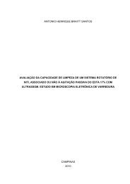
The dentin cube was then positioned in the center of the<br />
base of the test jig with the test surface against a Plexiglas<br />
plate (Fig 1), immobilized by slight pressure. A light-curing<br />
glass-ionomer cement (Fuji II LC capsules, GC Europe; Haasrode,<br />
Belgium) was mixed for 10 s followed by 3 s in a RotoMix<br />
device (3M ESPE; Seefeld, Germany), applied without<br />
prior conditioning of the dentin, and light cured for 20 s each<br />
at the bottom and top surfaces using a QTH light source<br />
(Luxor, ICI; Manchester, UK) with an output of at least 520<br />
mW/cm 2 . Output was checked with a radiometer (Optilux<br />
Model 100, SDS Kerr; Danury, CT, USA).<br />
The dentin test surface was prepared using a small piece<br />
of 600-grit grinding paper, cleaned with compressed air and<br />
water, and thereafter visually inspected under a light microscope.<br />
The test surface was then treated according to the<br />
manufacturer’s instructions for the respective materials.<br />
When separate acid etching was required, a phosphoric acid<br />
gel was used (Scotchbond etching gel, 3M ESPE), except<br />
when a proprietary etchant is included with the adhesive, as<br />
is the case for Prime & Bond NT. Polyacrylic acid (GC Conditioner,<br />
GC Europe) was used in case of the resin-modified<br />
glass-ionomer cement.<br />
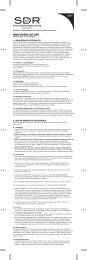
Once the final adhesive layer was finished for the dentin<br />
bonding, or the dentin was conditioned prior to the application<br />
of the resin-modified glass-ionomer cement, a perforated<br />
(diameter 1 mm) Mylar strip (0.05 mm thick) was accurately<br />
centered on top of the prepared sample and the upper<br />
part of the test jig was fixed (Fig 2). A first portion of the<br />
restorative was applied without touching the cavity walls and<br />
light cured. Next the remainder of the cavity was filled and<br />
cured incrementally.<br />
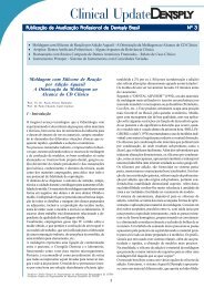
The test jig was then transferred to the fatigue machine<br />
and the screws removed (Fig 3). This method prevents the<br />
adhesive interface from being unintentionally touched or<br />
loaded by any means prior to testing.<br />
Fatigue Testing<br />
The present method is a modification of a previously described<br />
setup. 2 All testing was carried out at 35°C under<br />
load-controlled conditions, at a test frequency of 2 Hz.<br />
First, the quasi-static microshear strength (τ) was determined<br />
by measuring the maximal force at failure divided by<br />
the bonding surface area, which was measured under a light<br />
microscope prior to testing.<br />
During the fatigue test, the specimens were subjected to<br />
cyclic loading. Tests were conducted sequentially, with the<br />
initial stress set at about 50% of the microshear strength of<br />
250 The Journal of Adhesive Dentistry