EMER-FLEX COUPLING
EMER-FLEX COUPLING
EMER-FLEX COUPLING

You also want an ePaper? Increase the reach of your titles
YUMPU automatically turns print PDFs into web optimized ePapers that Google loves.
<strong>EMER</strong>-<strong>FLEX</strong> <strong>COUPLING</strong>
CONTENTS<br />
INDEX<br />
PRODUCT FEATURES<br />
PRODUCT STRUCTURE<br />
PRODUCT APPLICATIONS<br />
PRODUCT SELECTION<br />
MODEL LIST<br />
NEF-HUB<br />
NES Series<br />
P. 2<br />
P. 3-4<br />
P. 5-6<br />
P. 7-8<br />
P. 9-10<br />
P. 11<br />
P. 12<br />
P. 13-14<br />
NEF Series<br />
Spacer Type<br />
Long Spacer Type<br />
Stocked Long Spacer Type<br />
Short Spacer Type<br />
Single Type<br />
Clamping Method<br />
Power-Lock Method<br />
NEH Series<br />
Other Series<br />
INSTALLATION<br />
BORE SPECIFICATIONS<br />
P. 15-16<br />
P. 17-18<br />
P. 19<br />
P. 20<br />
P. 21-22<br />
P. 23-25<br />
P. 26-31<br />
P. 32-33<br />
P. 34-36<br />
P. 37-40<br />
P. 41-45<br />
1
INDEX<br />
PRODUCT SERIES LIST<br />
NES Series<br />
NEF<br />
Spacer Type<br />
Rough or keyed bore<br />
NEF<br />
Long Spacer Type<br />
Rough or keyed bore<br />
NEF<br />
Single Type<br />
Rough or keyed bore<br />
<br />
NES Series products are small disk couplings<br />
that use extra super duralumin.<br />
Both spacer-type and single-type couplings are<br />
available.<br />
<br />
With Spacer Type, two disk sets absorb angular<br />
misalignment, parallel misalignment and axial<br />
displacement.<br />
<br />
Long Spacer Type acts as a floating shaft when<br />
the distance between shaft ends is large.<br />
<br />
With Single Type, a single disk absorbs angular<br />
misalignment and axial displacement.<br />
NEF<br />
Clamping Method<br />
<br />
Refer to the page noted above when using the<br />
clamping method to connect to shafts (friction<br />
coupling by tightening one bolt).<br />
NEF<br />
Power-Lock Method<br />
<br />
Refer to the page noted above when using the<br />
Power-Lock method to connect to shafts.<br />
NEH Series<br />
<br />
NEH Series products are large-size, spacer type<br />
couplings.<br />
Other Series<br />
<br />
Tsubaki can manufacture a coupling to suit most any application, such as our G Type products that are compatible with gear couplings.<br />
2
<strong>EMER</strong>-<strong>FLEX</strong> <strong>COUPLING</strong><br />
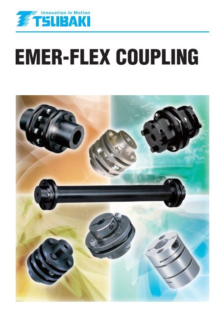
In order to make the <strong>EMER</strong>-<strong>FLEX</strong> <strong>COUPLING</strong> the ultimate disk coupling, Tsubaki optimized its design using finite element analysis. This coupling will<br />
meet all of your needs with no lubrication, no backlash, and with improved torsional stiffness for greater precision. This adds up to excellent flexible coupling<br />
performance for reliable torque transmission and absorption of shaft misalignment. Tsubaki offers a full line-up of <strong>EMER</strong>-<strong>FLEX</strong> couplings, from the smallsize<br />
precision NES Series offering a minimum of 0.7N·m torque transmission to the large size NEH Series delivering up to 176000N·m torque transmission.<br />
Our easy-to-select and convenient wide range of models include the Long Spacer Type, which functions as a floating shaft; the U-Type that enables spacer<br />
mounting and dismounting without disassembling the disk connecting section; the G-Type, which can replace gear couplings and other types that use various<br />
shaft coupling methods (Power-Lock, keyway, clamp, etc.) These <strong>EMER</strong>-<strong>FLEX</strong> couplings are ready to meet all of your next-generation coupling needs.<br />
Low moment of inertia<br />
(Square hub for Power-Lock)<br />
The original TSUBAKI design<br />
eliminates unnecessary flange<br />
portions.<br />
6<br />
<br />
Torsional Stiffness Curve<br />
Disk (Supports high torsional<br />
stiffness)<br />
Torsion Angle (degree)<br />
<br />
<br />
<br />
<br />
<br />
<br />
<br />
2<br />
<br />
<br />
<br />
0<br />
NEF10<br />
NEF18<br />
NEF25<br />
Strength analysis is used to determine<br />
the optimum shape.<br />
Torque<br />
3
PRODUCT FEATURES<br />
<br />
Finish–Bored Couplings<br />
Single-Type and Spacer-Type<br />
couplings with pre-machined,<br />
standard diameter shaft bores<br />
(new JIS key standard type)<br />
are always in stock and<br />
available for fast deliveries.<br />
<br />
Long Service Life<br />
With the anti-wear parts,<br />
the Emer-flex Couplings<br />
have an amazingly long<br />
useable life.<br />
<br />
Floating Shaft Function<br />
Long Spacer Type acts<br />
as a floating shaft,<br />
allowing the transmittance<br />
of power from a drive unit<br />
at some distance, without<br />
the use of bearings.<br />
<strong>EMER</strong>-<strong>FLEX</strong><br />
<br />
Lubrication Free<br />
<br />
Large Disk Bore<br />
<br />
Excellent Environmental Durability<br />
With no sliding or moving<br />
parts, there are no friction<br />
faces and lubrication is<br />
unnecessary.<br />
The disk bore in <strong>EMER</strong>-<br />
<strong>FLEX</strong> couplings can handle<br />
even the largest of shaft<br />
diameters. This enables<br />
various flexible installations<br />
(with shaft mounted in the<br />
disk, etc.).<br />
Because the Emerflex is an<br />
all-metal coupling without<br />
lubrication, it can stand up<br />
to high temperatures. The<br />
unit surface is also<br />
specially treated so it can<br />
withstand virtually any<br />
environment.<br />
<br />
No Backlash<br />
<br />
Original TSUBAKI Disk Design<br />
<br />
Easy Installation<br />
Torque is transmitted by<br />
friction connections, so there<br />
is no backlash and minimum<br />
hysteresis. This makes the<br />
Emerflex suitable for servo<br />
motor and other applications<br />
that need high-precision<br />
power transmissions.<br />
Our original disk design<br />
achieves high torsional<br />
stiffness and axial flexibility.<br />
The Power-Lock Type is equipped with an anti-rotation<br />
hole in the pressure flange, so tightening bolts is made<br />
easy, with no shaft rotation. With the U-Type couplings<br />
(Unit Spacer Type), the spacer can be mounted and<br />
dismounted without<br />
disassembling the disk<br />
connecting section.<br />
<br />
High Torsional Stiffness<br />
<br />
Axial Flexibility<br />
<br />
Quick Delivery<br />
With high torsional stiffness,<br />
elastic deformation is greatly<br />
reduced so even slight<br />
rotation movement is<br />
precisely transmitted to<br />
driven side.<br />
When the motor shaft<br />
expands due to heat<br />
generated during operation,<br />
the coupling absorbs the<br />
expansion and does not<br />
generate unnecessary thrust<br />
power against bearing.<br />
In addition to our product<br />
inventory with standard<br />
shaft bore diameters,<br />
Tsubaki can offer<br />
products with other shaft<br />
bore diameters with<br />
short delivery times.<br />
<br />
Low Moment of Inertia<br />
<br />
Excellent with Servo Motors<br />
<br />
Standardized Power-Lock Types<br />
We have eliminated<br />
unnecessary flange portions,<br />
and offer a unique square<br />
hub, resulting in minimum<br />
moment of inertia. With the<br />
NES Series, the hub and<br />
spacer are made of extra<br />
super duralumin, which<br />
considerably reduces weight.<br />
A new production method<br />
makes this coupling strong<br />
and lightweight. With the<br />
addition of the NES Series,<br />
we have couplings that are<br />
suitable for small to large<br />
servo motor.<br />
All Emerflex couplings<br />
come standard with a<br />
Power-Lock. So each<br />
is provided with a<br />
pressure plate and<br />
pressure bolt.<br />
4
PRODUCT STRUCTURE<br />
NEF Series<br />
Spacer Type<br />
Spacer<br />
U-nut<br />
Washer A<br />
Disk<br />
Washer B<br />
Washer A<br />
Washer B<br />
Reamer bolt<br />
Hub<br />
Single Type<br />
Power-Lock Type<br />
U-nut<br />
Disk<br />
Disk<br />
Washer B<br />
Washer A<br />
Reamer bolt<br />
Washer A<br />
Pressure bolt<br />
Washer B<br />
U-nut<br />
Hub<br />
Pressure<br />
flange<br />
Power-Lock<br />
Reamer bolt<br />
Hub<br />
NES Series<br />
NEH Series<br />
Overload<br />
washer<br />
Collar<br />
Bush<br />
Washer<br />
Washer<br />
The disk, bush and collar<br />
are all integrated.<br />
Disk<br />
Hexagon socket<br />
head bolt<br />
Disk set<br />
U-nut<br />
Overload<br />
washer<br />
Hub<br />
Spacer<br />
Reamer bolt<br />
Washer<br />
Spacer<br />
Washer<br />
Hub<br />
5
NEF Series<br />
Long Spacer Type<br />
Spacer<br />
<strong>EMER</strong>-<strong>FLEX</strong><br />
Washer A<br />
Washer B<br />
U-nut<br />
Washer B<br />
Hub<br />
U-nut<br />
Reamer bolt<br />
Washer A<br />
Disk<br />
NEH Series<br />
Long Spacer Type<br />
Overload<br />
washer<br />
Collar<br />
Bush<br />
U-nut<br />
Hub<br />
Overload<br />
washer<br />
The disk, bush and collar are all integrated.<br />
Disk set<br />
Reamer bolt<br />
Spacer<br />
6
PRODUCT APPLICATIONS<br />
NC machining centers<br />
Lifters<br />
Servo motor<br />
Emer-Flex Coupling<br />
Emer-Flex Coupling<br />
Table<br />
Ball screw<br />
LINIPOWER Jack<br />
Emer-Flex Coupling<br />
(Power-Lock Type)<br />
Windmills<br />
Printing presses<br />
Generator<br />
Emer-Flex Coupling<br />
Gear box<br />
Gear box<br />
Emer-Flex Coupling<br />
Speed increaser<br />
Robots<br />
Elevator-type vertical parking lots<br />
Servo motor<br />
Roller chain<br />
Emer-Flex Coupling<br />
Bevel helical reduction gear<br />
Emer-Flex Coupling<br />
Ball screw<br />
Emer-Flex Coupling<br />
NES Series<br />
7
Example of Mounting<br />
<strong>EMER</strong>-<strong>FLEX</strong><br />
Example of Mounting<br />
8
PRODUCT SELECTION<br />
1. Correct torque calculation<br />
1-1. When connecting to a servo motor or stepping motor<br />
To determine the correct torque, multiply the maximum torque of the servo motor or<br />
stepping motor by the service factor (SF) corresponding to the type of load listed in the<br />
table below.<br />
Service Factor (SF) Table<br />
Type of Load<br />
Service Factor (SF)<br />
Constant Load<br />
1.2<br />
Mid-Level Variable Load<br />
1-2. When connecting to a general-purpose motor<br />
To determine the correct torque, multiply the load torque calculated with the following<br />
formula by the service factor (SF) corresponding to the type of load listed in the table on<br />
the right.<br />
⎧<br />
⎫<br />
⎨<br />
⎬<br />
⎩ ⎭<br />
<br />
TLoad torque<br />
PTransmission power<br />
nRotation speed<br />
TCorrect torque<br />
N·m {kgf·m}<br />
kW<br />
r/min<br />
N·m {kgf·m}<br />
1.4<br />
Heavy Variable Load<br />
1.5<br />
Service Factor (SF) Table<br />
Type of Load<br />
General-Purpose Motor / Gas Turbine<br />
Low Moment<br />
of Inertia<br />
High Moment<br />
of Inertia<br />
Type of Motor<br />
2. Shaft Diameter<br />
Make sure that the target shaft diameter does not exceed the allowable mounting shaft diameter for the coupling.<br />
With the Power-Lock, check the power lock size, quantity and transmission torque.<br />
With the clamp type, make sure that the correct torque determined in Item (1) does not exceed the allowable transmission torque for the clamp.<br />
3. Maximum Rotation Speed for Long Spacer Types<br />
When using the Long Spacer Type coupling at a high speed rotation, the rotation speed must be checked in order to avoid the resonance point.<br />
When selecting the Long Spacer Type coupling, make sure that the maximum dimension “J” and the rotation speed for each model are not exceeded.<br />
If the operating rotation speed exceeds the specified value, a larger model number must be selected.<br />
If the operating rotation speed is not within the following range, or if the selection of a larger model number is not an option, a “High-Speed Type<br />
Long Spacer” coupling can be manufactured as one solution. (See p. 36)<br />
Engine<br />
4-Cylinder 6-Cylinder 8-Cylinder<br />
Constant Load 1.51.75 1.752.0 2.54.0 2.02.5 1.52.0<br />
Mid-Level Variable Load 2.02.5 2.53.0 4.05.0 2.53.5 2.03.0<br />
Heavy Variable Load 3.04.5 4.56.0 4.55.5 3.04.0 2.53.5<br />
* If an impact load is expected, determine the correct torque by multiplying the<br />
maximum torque rated for the motor by an impact factor of 1 to 2.5.<br />
* When clamp or power lock method is used, do not allow torque that is larger than<br />
the shaft bore friction transmission torque (see p. 25 and p. 31), including the<br />
starting torque, even for an instant.<br />
Model No.<br />
Operating Rotation Speed<br />
r/min<br />
3600<br />
Long Spacer Maximum Length (Dimension “J”)<br />
Unit: mm<br />
2000 1800 1500 1200 1000 900 750 720 600 500 400 300 200 150<br />
NEF 04W<br />
NEF 10W<br />
NEF 18W<br />
NEF 25W<br />
NEF 45W<br />
NEF 80W<br />
NEF130W<br />
NEF210W<br />
NEF340W<br />
NEF540W<br />
NEF700W<br />
NEH 09W<br />
NEH 14W<br />
NEH 20W<br />
NEH 30W<br />
NEH 41W<br />
980 1310 1380 1510 1680 1840 1940 2130 2170 2380 2610 2910 3360 4120 4750<br />
1120 1500 1580 1730 1940 2120 2230 2450 2500 2730 2990 3350 3860 4730 5460<br />
1180 1580 1660 1820 2040 2230 2350 2570 2620 2870 3150 3520 4060 4970 5740<br />
1310 1760 1850 2030 2260 2480 2610 2860 2920 3190 3500 3910 4510 5520<br />
1440 1930 2030 2230 2490 2720 2870 3140 3210 3510 3840 4290 4960<br />
1560 2090 2200 2410 2690 2950 3100 3400 3470 3800 4160 4650 5360<br />
1780 2380 2510 2750 3070 3360 3540 3870 3950 4330 4740 5290<br />
1890 2520 2660 2910 3250 3560 3750 4100 4190 4580 5020 5610<br />
2024 2720 2870 3130 3500 3830 4040 4420 4510 4930 5400<br />
2180 2910 3070 3360 3750 4100 4320 4730 4820 5280 5780<br />
2270 3030 3190 3490 3890 4260 4490 4910 5010 5490<br />
2190 2930 3090 3380 3780 4130 4360 4770 4870 5330 5830<br />
2190 2930 3090 3380 3780 4130 4360 4770 4870 5330 5830<br />
2400 3200 3380 3690 4130 4520 4760 5210 5320 5820<br />
2570 3430 3610 3960 4420 4840 5100 5580 5690<br />
2650 3540 3730 4080 4560 4990 5260 5760 5870<br />
9
4. Precautions for Connecting a Servo Motor Drive System<br />
Depending on the natural frequency and electric control status of the system as a whole, a ball screw drive system using a servo motor may generate<br />
large vibration or abnormal sound caused by oscillation due to the characteristics of the servo motor. In this case, adjust the torsional stiffness and<br />
moment of inertia of the overall drive system to increase the torsional natural frequency, or adjust the servo gain with the electric control tuning<br />
function of the servo motor.<br />
5. Select the <strong>EMER</strong>-<strong>FLEX</strong> Coupling that Meets the above Requirements, 1 through 4, from the<br />
Transmission Capacity Table.<br />
<strong>EMER</strong>-<strong>FLEX</strong><br />
Dynamic Balance Adjustment<br />
Normally, because <strong>EMER</strong>-<strong>FLEX</strong> couplings provide a well-balanced design, they need no particular balance adjustment. However, when the coupling<br />
is used at a high rotation speed, or when a long spacer is used, balance adjustment may be required.<br />
In this case, inform us of your desired operating rotation speed, JIS balance rating, dimension “J”, or spacer length so that we can perform your<br />
balance adjustment.<br />
For dynamic balance adjustment, we use the following two methods:<br />
1) Drilling the spacer flange end face, and<br />
2) Mounting a balance weight to the spacer pipe periphery. (The spacer with a balance weight is shown below. The balance weight mounting position<br />
and quantity vary depending on operating conditions. Be careful not to interfere with the balance weight during rotation.)<br />
When requesting a balance adjustment, specify either method 1) or 2) above.<br />
Balance weight<br />
A Spacer Mounted with a Balance weight<br />
Notes for Large Distance between Shaft<br />
Ends<br />
For large distance between shaft ends, Tsubaki offers a Long Spacer<br />
Type that can be used in a floating state without the need for an<br />
intermediate shaft bearing. We recommend this type of coupling if it fits<br />
your application needs.<br />
If an intermediate shaft bearing is being used instead of the Long Spacer<br />
Type coupling for reasons of convenience, fasten the intermediate shaft<br />
with a bearing to prevent the intermediate shaft from floating. In this<br />
case, it is recommended that the Spacer-Type disk coupling be used.<br />
Long Spacer Type<br />
Spacer Type + Fixed intermediate shaft + Spacer Type<br />
If the distance between shafts is short and an intermediate shaft is used<br />
in a floating condition, be sure to use the Single-Type coupling.<br />
Never use the Spacer-Type coupling under such conditions; it is very<br />
dangerous due to the marked floating tendency of the intermediate<br />
shaft.<br />
Single Type + Floating intermediate shaft + Single Type<br />
Spacer Type + Floating intermediate shaft + Spacer Type<br />
Pay special attention to the above when replacing gear couplings or roller chain couplings with disk couplings.<br />
10
MODEL LIST<br />
Model No.<br />
NES07<br />
NES15<br />
NES20<br />
NES30<br />
NES50<br />
NES70<br />
NES100<br />
NES250<br />
NES800<br />
NES1300<br />
NEF02<br />
NEF04<br />
NEF10<br />
NEF18<br />
NEF25<br />
NEF45<br />
NEF80<br />
NEF130<br />
NEF210<br />
NEF340<br />
NEF540<br />
NEF700<br />
NEH09<br />
NEH14<br />
NEH20<br />
NEH30<br />
NEH41<br />
NEH55<br />
Type<br />
Allowable<br />
Torque<br />
Nm<br />
{kfm}<br />
0.7<br />
{ 0.07 }<br />
1.5<br />
{ 0.15 }<br />
2<br />
{ 0.2 }<br />
3<br />
{ 0.31}<br />
5<br />
{ 0.51}<br />
7<br />
{ 0.71}<br />
10<br />
{ 1 }<br />
25<br />
{ 2.6 }<br />
80<br />
{ 8.2 }<br />
130<br />
{ 13 }<br />
19.6<br />
{ 2 }<br />
39.2<br />
{ 4 }<br />
98<br />
{ 10 }<br />
176<br />
{ 18 }<br />
245<br />
{ 25 }<br />
441<br />
{ 45 }<br />
784<br />
{ 80 }<br />
1270<br />
{ 130 }<br />
2060<br />
{ 210 }<br />
3330<br />
{ 340 }<br />
5290<br />
{ 540 }<br />
6860<br />
{ 700 }<br />
8820<br />
{ 900 }<br />
13700<br />
{ 1400 }<br />
19600<br />
{ 2000 }<br />
29400<br />
{ 3000 }<br />
40200<br />
{ 4100 }<br />
53900<br />
{ 5500 }<br />
Keyway Max.<br />
Bore Diameter<br />
Standard Extended-<br />
Hub Dia. Hub<br />
Rough<br />
Bore<br />
(Spacer<br />
Type)<br />
Rough<br />
Bore<br />
(Single<br />
Type)<br />
Standard<br />
Length<br />
(Long Spacer<br />
Type)<br />
Long<br />
Spacer<br />
Type<br />
Type of Hub<br />
Extended-<br />
Dia. Hub<br />
<br />
<br />
<br />
<br />
<br />
<br />
<br />
<br />
<br />
<br />
<br />
20 25<br />
<br />
<br />
23 28 <br />
<br />
32 40 <br />
35 42 <br />
42 48 <br />
50 60 <br />
60 70 <br />
74 80 <br />
83 90 <br />
95 110 <br />
109 120 <br />
118 130 <br />
111 (158) <br />
111<br />
133<br />
152<br />
165<br />
187<br />
(158)<br />
(182)<br />
(206)<br />
(224)<br />
<br />
<br />
<br />
<br />
<br />
<br />
<br />
<br />
<br />
<br />
<br />
Standard<br />
Hub<br />
<br />
<br />
<br />
<br />
<br />
Long<br />
Hub<br />
Square<br />
Hub<br />
Keyway<br />
<br />
<br />
<br />
<br />
<br />
Bore Machining<br />
G-Type A-Hub<br />
Power-<br />
U-Type<br />
Tapered Bore Type<br />
Clamp<br />
Lock 11,16<br />
<br />
<br />
<br />
<br />
<br />
<br />
<br />
<br />
<br />
<br />
<br />
<br />
<br />
<br />
<br />
<br />
<br />
<br />
<br />
<br />
<br />
<br />
NEH70<br />
68600<br />
{ 7000 }<br />
205<br />
<br />
<br />
<br />
<br />
<br />
NEH90<br />
88200<br />
{ 9000 }<br />
231<br />
<br />
<br />
<br />
<br />
<br />
NEH110<br />
107800<br />
{ 11000 }<br />
254<br />
<br />
<br />
<br />
<br />
<br />
NEH135<br />
132300<br />
{ 13500 }<br />
263<br />
<br />
<br />
<br />
<br />
<br />
NEH150<br />
147000<br />
{ 15000 }<br />
275<br />
<br />
<br />
<br />
<br />
<br />
NEH180<br />
176400<br />
{ 18000 }<br />
289<br />
<br />
<br />
<br />
<br />
<br />
Values in parentheses for the NEH09 to NEH41 apply to the A-hub and U-types.<br />
Standard<br />
Custom-made<br />
11
DIMENSIONS<br />
<br />
NEF Series Hub Dimensions<br />
Extended-Diameter Hubs<br />
If the target shaft diameter exceeds the maximum shaft bore diameter of the standard hub regardless of there being sufficient leeway in the<br />
transmission capacity, you may select the extended-diameter hub that provides a larger boss diameter (dimension “H”). This way you can avoid<br />
increasing the model size.<br />
Long Hubs<br />
If the key surface pressure is too high with the standard hub, you may select the long hub that provides a longer dimension “B”, which lowers the key<br />
surface pressure.<br />
Square Hubs<br />
The square hub is used as a combination with the EL Series Power-Lock Type coupling and the pressure flange set. The pressure bolt tap has been<br />
machined into the hub.<br />
<strong>EMER</strong>-<strong>FLEX</strong><br />
Standard Hub / Long Hub<br />
Extended-Dia. Hub<br />
Square Hub<br />
Max. bore dia.<br />
Max. bore dia.<br />
Max. bore dia.<br />
H<br />
DIMENSIONS<br />
Model No.<br />
Unit: mm<br />
B H Max. Bore Dia.<br />
Rough Bore<br />
K Standard Hub<br />
Standard Hub Extended-<br />
Standard Hub / Long Hub Extended-Dia. Hub Square Hub<br />
Extended- Long Hub Square Hub<br />
Long Hub Dia. Hub<br />
Square Hub d<br />
Dia. Hub<br />
Keyway Power-Lock Keyway Power-Lock Power-Lock<br />
NEF02<br />
NEF04<br />
NEF10<br />
NEF18<br />
NEF25<br />
NEF45<br />
NEF80<br />
NEF130<br />
NEF210<br />
NEF340<br />
NEF540<br />
NEF700<br />
57<br />
67.5<br />
81<br />
93<br />
104<br />
126<br />
143<br />
168<br />
194<br />
214<br />
246<br />
276<br />
20<br />
25.4<br />
25.4<br />
28.7<br />
33.5<br />
41.1<br />
47.8<br />
57.2<br />
63.5<br />
76.2<br />
88.9<br />
101.6<br />
—<br />
40<br />
40<br />
45<br />
50<br />
60<br />
70<br />
85<br />
120<br />
140<br />
140<br />
150<br />
*<br />
Note: Only the standard hub can be used with the NEF02.<br />
—<br />
—<br />
25.4<br />
28.7<br />
33.5<br />
—<br />
—<br />
—<br />
—<br />
—<br />
—<br />
—<br />
32<br />
34<br />
46<br />
51<br />
61<br />
71<br />
84<br />
106<br />
118<br />
137<br />
156<br />
169<br />
* Note 1<br />
45<br />
50<br />
66<br />
66<br />
78<br />
92<br />
104<br />
129<br />
147<br />
166<br />
191<br />
209<br />
—<br />
—<br />
47<br />
49<br />
60<br />
—<br />
—<br />
—<br />
—<br />
—<br />
—<br />
—<br />
8<br />
8<br />
10<br />
12<br />
15<br />
15<br />
15<br />
25<br />
25<br />
45<br />
50<br />
50<br />
20<br />
23<br />
32<br />
35<br />
42<br />
50<br />
60<br />
74<br />
83<br />
95<br />
109<br />
118<br />
—<br />
—<br />
—<br />
—<br />
—<br />
35<br />
45<br />
65<br />
71<br />
85<br />
—<br />
—<br />
25<br />
28<br />
40<br />
42<br />
48<br />
60<br />
70<br />
80<br />
90<br />
110<br />
120<br />
130<br />
20<br />
22<br />
30<br />
35<br />
42<br />
50<br />
60<br />
75<br />
85<br />
100<br />
110<br />
120<br />
—<br />
—<br />
35<br />
35<br />
42<br />
—<br />
—<br />
—<br />
—<br />
—<br />
—<br />
—<br />
Hub for Taper Shaft Bore<br />
For a 16 taper shaft bore, the following four types of hubs are available in stock:<br />
NEF04 Hub-16T NEF04 Hub-L16T NEF10 Hub-16T NEF10 Hub-L16T<br />
Dimension ÒAÓ<br />
Dimension ÒAÓ<br />
Dimension<br />
ÒDÓ<br />
Dimension ÒDÓ<br />
Taper<br />
Servo motor shaft<br />
Servo motor shaft<br />
Servo motor shaft<br />
Servo motor shaft<br />
12
TRANSMISSION CAPACITY / DIMENSIONS<br />
<br />
Small-Size, Precision: NES Series<br />
High torsional stiffness<br />
The high torsional stiffness enables the couplings to provide excellent trackability for<br />
servo motors, making the NES Series perfect for precision control applications.<br />
Compact & low moment of inertia<br />
NES Series couplings employ extra super duralumin in the hub and the spacer, resulting<br />
in a compact body. With the reduced outer diameter, this type also lowers the moment of<br />
inertia.<br />
RoHS compliant<br />
The NES Series offers environmentally conscious designs that comply with the RoHS<br />
Directive.<br />
Shipment of fully assembled parts <br />
NES Series couplings are shipped as a complete assembly (with finished bores), so the<br />
coupling can be directly mounted to your equipment.<br />
NES Spacer Type Couplings<br />
X<br />
Reference Number System (Example)<br />
K<br />
D<br />
D<br />
NES30W - N10C X N12C<br />
O<br />
Y<br />
B<br />
E<br />
J<br />
A<br />
E<br />
B<br />
Series<br />
Size<br />
Spacer Type<br />
Bore Diameter (mm)<br />
<br />
Clamp<br />
Type of Hub<br />
N: Standard Hub<br />
*<br />
Indicate the smaller bore diameter first.<br />
Model No.<br />
NES07W<br />
NES15W<br />
NES20W<br />
NES30W<br />
NES50W<br />
NES70W<br />
NES100W<br />
NES250W<br />
NES800W<br />
NES1300W<br />
Notes<br />
Allowable<br />
Torque<br />
Nm<br />
{kfm}<br />
Cross-section X-O-Y<br />
(Note 5) (Note 1) (Notes 4, 6) Torsional Stiffness<br />
(Note 3) (Note 2) (Note 2) (Note 2)<br />
Clamp Bore Dia.<br />
Dimensions<br />
Nm/rad<br />
Moment<br />
mm<br />
Allowable Misalignment<br />
D mm<br />
{kfm/rad}<br />
Weight of Inertia GD 2<br />
0.7<br />
{0.07}<br />
1.5<br />
{0.15}<br />
2.0<br />
{0.20}<br />
3.0<br />
{0.31}<br />
5.0<br />
{0.51}<br />
7.0<br />
{0.71}<br />
10<br />
{1.0}<br />
25<br />
{2.6}<br />
80<br />
{8.2}<br />
130<br />
{13}<br />
Max.<br />
Rotation<br />
speed Bore Dia.<br />
r/min Range<br />
18000<br />
18000<br />
18000<br />
18000<br />
18000<br />
18000<br />
15000<br />
10000<br />
10000<br />
10000<br />
4-6<br />
4-8<br />
5-10<br />
6-16<br />
6-16<br />
8-20<br />
8-22<br />
10-25<br />
14-30<br />
20-35<br />
Standard<br />
Bore Dia.<br />
Refer to the ÒStandard bore diameter and the transmission torque<br />
for each bore diameterÓ table (on the next page).<br />
A B E K J<br />
18.9<br />
26<br />
31.7<br />
35.6<br />
40<br />
45.5<br />
48.1<br />
59<br />
70.9<br />
97.9<br />
7.5<br />
8.9<br />
11<br />
11.8<br />
12.5<br />
15<br />
15.7<br />
20<br />
23.5<br />
31.5<br />
0.85<br />
1.1<br />
1.1<br />
1.5<br />
1.5<br />
1.75<br />
2.6<br />
3<br />
4.7<br />
5.2<br />
16<br />
19<br />
24<br />
31<br />
34<br />
37<br />
44<br />
55<br />
64<br />
82<br />
12<br />
15<br />
3.9<br />
8.2<br />
9.7<br />
15.5<br />
16.7<br />
19<br />
23.9<br />
34.9<br />
Whole<br />
Coupling<br />
Disk<br />
Only<br />
210 600<br />
{21} {61}<br />
420 1300<br />
{43} {130}<br />
1000 2800<br />
{100} {290}<br />
1600 4200<br />
{160} {430}<br />
2100 6500<br />
{210} {660}<br />
4600 9500<br />
{470} {970}<br />
6200 15000<br />
{630} {1500}<br />
11000 22000<br />
{1100} {2200}<br />
23000 39000<br />
{2300} {4000}<br />
46000 110000<br />
{4700} {11000}<br />
Axial<br />
Spring<br />
Constant<br />
N/mm<br />
{kf/mm}<br />
87<br />
{8.9}<br />
47<br />
{4.8}<br />
43<br />
{4.4}<br />
24<br />
{2.4}<br />
25<br />
{2.6}<br />
29<br />
{3.0}<br />
33<br />
{3.4}<br />
11<br />
{1.1}<br />
27<br />
{2.8}<br />
33<br />
{3.4}<br />
Angular<br />
Misalignment<br />
deg<br />
1.4<br />
2.0<br />
2.0<br />
2.0<br />
2.0<br />
2.0<br />
2.0<br />
2.0<br />
2.0<br />
2.0<br />
Parallel<br />
Misalignment<br />
mm<br />
0.05<br />
0.12<br />
0.15<br />
0.18<br />
0.24<br />
0.24<br />
0.25<br />
0.28<br />
0.34<br />
0.52<br />
Axial<br />
Displacement<br />
mm<br />
0.24<br />
0.36<br />
0.60<br />
0.80<br />
0.80<br />
0.90<br />
1.1<br />
1.4<br />
1.4<br />
1.8<br />
g<br />
9<br />
17<br />
32<br />
53<br />
76<br />
97<br />
160<br />
320<br />
510<br />
1200<br />
km 2<br />
{kfcm 2 }<br />
{0.01}<br />
0.3210 -6<br />
1100 10 -6 {45}<br />
0.9010 -6<br />
2.7 10 -6<br />
8.0 10 -6<br />
{0.04}<br />
{0.11}<br />
{0.32}<br />
14 10 -6 {0.54}<br />
21 10 -6 {0.84}<br />
47 10 -6 {1.9}<br />
140 10 -6 {5.7}<br />
320 10 -6 {13}<br />
1. The maximum rotation speed does not take dynamic balance into consideration.<br />
2. The weight, moment of inertia and GD 2 are the values at maximum bore diameter.<br />
3. The allowable misalignment is based on the assumption that other errors are Ò0Ó.<br />
4. Bore diameters other than the standard diameters specified on p. 14 can be manufactured upon request.<br />
5. Depending on the bore diameter, the allowable torque of the coupling may not be satisfied. Refer to the ÒStandard Bore Diameter and Transmission Torque for Each Bore<br />
DiameterÓ table (on the next page).<br />
6. The recommended tolerance of the mounting shaft is rated at Òh7Ó. A shaft diameter of 35 corresponds to a servo motor shaft with a tolerance of (+0.010 to 0).<br />
13
NES Single Type Couplings<br />
K<br />
D<br />
D<br />
O<br />
X<br />
Y<br />
Reference Number System (Example)<br />
NES30S - N10C X N12C<br />
<strong>EMER</strong>-<strong>FLEX</strong><br />
E<br />
B B<br />
A<br />
Cross-section X-O-Y<br />
Series<br />
Size<br />
Single Type<br />
Bore Diameter (mm)<br />
Indicated as Ò6.3Ó for a<br />
6.35 bore diameter<br />
and Ò9.5Ó for a 9.525<br />
<br />
bore diameter.<br />
Type of Hub<br />
N: Standard Hub<br />
*<br />
Indicate the smaller bore diameter first.<br />
Clamp<br />
Model No.<br />
NES07S<br />
NES15S<br />
NES20S<br />
NES30S<br />
NES50S<br />
NES70S<br />
NES100S<br />
NES250S<br />
NES800S<br />
NES1300S<br />
Notes<br />
(Note 5) (Note 1) (Notes 4, 6) Torsional Stiffness<br />
(Note 3) (Note 2) (Note 2) (Note 2)<br />
Clamp Bore Dia.<br />
Dimensions<br />
Nm/rad<br />
Moment<br />
mm<br />
Allowable Misalignment<br />
D mm<br />
{kfm/rad}<br />
Weight of Inertia GD 2<br />
Allowable Max.<br />
Torque Rotation<br />
Nm Speed<br />
{kfm} r/min<br />
0.7<br />
{0.07}<br />
1.5<br />
{0.15}<br />
2.0<br />
{0.20}<br />
3.0<br />
{0.31}<br />
5.0<br />
{0.51}<br />
7.0<br />
{0.71}<br />
10<br />
{1.0}<br />
25<br />
{2.6}<br />
80<br />
{8.2}<br />
130<br />
{13}<br />
18000<br />
18000<br />
18000<br />
18000<br />
18000<br />
18000<br />
15000<br />
10000<br />
10000<br />
10000<br />
Bore Dia.<br />
Range<br />
4-6<br />
4-8<br />
5-10<br />
6-16<br />
6-16<br />
8-20<br />
8-22<br />
10-25<br />
14-30<br />
20-35<br />
Standard<br />
Bore Dia.<br />
Refer to the ÒStandard bore diameter and the transmission torque<br />
for each bore diameterÓ table below.<br />
15.85<br />
18.9<br />
23.1<br />
25.1<br />
26.5<br />
31.75<br />
34<br />
43<br />
A B E K<br />
51.7<br />
68.2<br />
11<br />
7.5<br />
8.9<br />
11.8<br />
12.5<br />
15<br />
15.7<br />
20<br />
23.5<br />
31.5<br />
0.85<br />
1.1<br />
1.1<br />
1.5<br />
1.5<br />
1.75<br />
2.6<br />
3<br />
4.7<br />
5.2<br />
16<br />
19<br />
24<br />
31<br />
34<br />
37<br />
44<br />
55<br />
64<br />
82<br />
Whole<br />
coupling<br />
Disk<br />
only<br />
430 1200<br />
{44} {120}<br />
780 2600<br />
{80} {270}<br />
1800 5600<br />
{180} {570}<br />
3700 8400<br />
{380} {860}<br />
4500 13000<br />
{460} {1300}<br />
7400 19000<br />
{760} {1900}<br />
10000 30000<br />
{1000} {3000}<br />
19000 44000<br />
{1900} {4500}<br />
39000 78000<br />
{4000} {8000}<br />
77000 220000<br />
{7900} {22000}<br />
Axial<br />
Spring<br />
Constant<br />
N/mm<br />
{kf/mm}<br />
170<br />
{17}<br />
93<br />
{9.5}<br />
86<br />
{8.8}<br />
48<br />
{4.9}<br />
51<br />
{5.2}<br />
58<br />
{5.9}<br />
65<br />
{6.6}<br />
21<br />
{2.1}<br />
52<br />
{5.3}<br />
65<br />
{6.6}<br />
Angular<br />
Misalignment<br />
deg<br />
0.7<br />
1.0<br />
1.0<br />
1.0<br />
1.0<br />
1.0<br />
1.0<br />
1.0<br />
1.0<br />
1.0<br />
Parallel<br />
Misalignment<br />
mm<br />
0.02 0.12<br />
0.02 0.18<br />
0.02 0.30<br />
0.02 0.40<br />
0.02 0.40<br />
0.02 0.45<br />
0.02 0.55<br />
0.02 0.70<br />
0.02 0.70<br />
0.02 0.90<br />
7<br />
12<br />
23<br />
37<br />
49<br />
66<br />
110<br />
220<br />
350<br />
790<br />
{0.01}<br />
0.2610 -6<br />
770 10 -6 {31}<br />
0.6310 -6<br />
1.9 10 -6<br />
5.5 10 -6<br />
8.8 10 -6<br />
{0.03}<br />
{0.08}<br />
{0.22}<br />
{0.35}<br />
14 10 -6 {0.57}<br />
32 10 -6 {1.3}<br />
100 10 -6 {4.1}<br />
220 10 -6 {8.7}<br />
1. The maximum rotation speed does not take dynamic balance into consideration.<br />
2. The weight, moment of inertia and GD 2 are the values at maximum bore diameter.<br />
3. The allowable misalignment is based on the assumption that other errors are Ò0Ó.<br />
4. Bore diameters other than the standard diameters specified below can be manufactured upon request.<br />
5. Depending on the bore diameter, the allowable torque of the coupling may be limited. Refer to the ÒStandard Bore Diameter and Transmission Torque for Each Bore<br />
DiameterÓ table below.<br />
6. The recommended tolerance of the mounting shaft is rated at Òh7Ó. A shaft diameter of 35 corresponds to a servo motor shaft with a tolerance of (+0.010 to 0).<br />
Unit: N·m<br />
Axial<br />
Displacement<br />
mm<br />
g<br />
km 2<br />
{kfcm 2 }<br />
Standard Bore Diameter and Transmission Torque for Each Bore Diameter<br />
Bore Diameter<br />
(mm)<br />
Model No.<br />
4<br />
5<br />
6<br />
6.35<br />
7<br />
8<br />
9<br />
9.525<br />
10<br />
11<br />
12<br />
14<br />
15<br />
16<br />
17<br />
18<br />
19<br />
20<br />
22<br />
24<br />
25<br />
28<br />
30<br />
32<br />
35<br />
NES07<br />
NES15<br />
NES20<br />
NES30<br />
NES50<br />
NES70<br />
NES100<br />
NES250<br />
NES800<br />
NES1300<br />
0.7<br />
1.3<br />
0.7<br />
1.5<br />
2<br />
0.7<br />
1.5<br />
2<br />
3<br />
5<br />
1.5<br />
2<br />
3<br />
5<br />
1.5<br />
2<br />
3<br />
5<br />
1.5<br />
2<br />
3<br />
5<br />
7<br />
10<br />
2<br />
3<br />
5<br />
7<br />
10<br />
2<br />
3<br />
5<br />
7<br />
10<br />
2<br />
3<br />
5<br />
7<br />
10<br />
25<br />
3<br />
5<br />
7<br />
10<br />
25<br />
3<br />
5<br />
7<br />
10<br />
25<br />
3<br />
5<br />
7<br />
10<br />
25<br />
80<br />
3<br />
5<br />
7<br />
10<br />
25<br />
80<br />
3<br />
5<br />
7<br />
10<br />
25<br />
80<br />
7<br />
10<br />
25<br />
80<br />
7<br />
10<br />
25<br />
80<br />
7<br />
10<br />
25<br />
80<br />
7<br />
10<br />
25<br />
80<br />
107<br />
10<br />
25<br />
80<br />
118<br />
25<br />
80<br />
130<br />
25<br />
80<br />
130<br />
80<br />
130<br />
80<br />
130<br />
130 130<br />
14
TRANSMISSION CAPACITY / DIMENSIONS<br />
<br />
NEF Series: Spacer Type Couplings<br />
The NEF Series Spacer Type coupling incorporates two sets of<br />
disk kits, enabling absorption of all misalignments.<br />
This type of coupling provides the widest application range.<br />
NEF02W - N X N<br />
Note: The spacer shape is different<br />
from that of other sizes. The<br />
standard hub and extendeddiameter<br />
hub are in stock.<br />
Contact us for long hubs.<br />
1<br />
Standard HubStandard Hub NEFW -N XN Extended-Dia. HubStandard Hub NEFW -K XN<br />
Standard hub Reamer bolt Washer A Washer B<br />
Disk U-nut Spacer Set screw<br />
Standard hub Extended-dia. hub Reamer bolt Washer A<br />
Washer B Disk U-nut Spacer Set screw<br />
Long HubStandard Hub NEFW -L XN Extended-Dia. HubExtended-Dia. Hub NEFW -K XK<br />
Long hub Standard hub Reamer bolt Washer A<br />
Washer B Disk U-nut Spacer Set screw<br />
Extended-dia. hub Reamer bolt Washer A Washer B<br />
Disk U-nut Spacer Set screw<br />
Extended-Dia. HubLong Hub NEFW -K XL Long HubLong Hub NEFW -L XL<br />
Extended-dia. hub Long hub Reamer bolt Washer A<br />
Washer B Disk U-nut Spacer Set screw<br />
Long hub Reamer bolt Washer A Washer B<br />
Disk U-nut Spacer Set screw<br />
15
Spacer Type<br />
Model No.<br />
Allowable<br />
Torque<br />
Nm{kfm}<br />
Max.<br />
Rotation<br />
Speed<br />
r/min<br />
Rough<br />
Bore<br />
d<br />
Keyway<br />
Standard<br />
Stock Bore<br />
Dia. Range<br />
Keyway Max. Shaft Dia.<br />
Standard<br />
Hub<br />
Long<br />
Hub<br />
Extended-<br />
Dia. Hub<br />
Torsional Stiffness<br />
Nm/rad{kfm/rad}<br />
Axial Spring<br />
Constant<br />
N/mm{kf/mm}<br />
Unit: mm<br />
A1 A2 A3<br />
NEF02W 19.6{ 2} 20000 8 14-25 20 25 1.0010 4 { 0.1010 4 } 34.3{ 3.5} 44 63 <br />
NEF04W 39.2{ 4} 20000 8 11-22 23 23 29 1.1810 4 { 0.1210 4 } 20.6{ 2.1} 49.5 86.8 101.4 116<br />
NEF10W 98 { 10} 20000 10 12-30 32 32 40 3.9210 4 { 0.4 10 4 } 29.4{ 3 } 63 89.8 104.4 119<br />
NEF18W 176 { 18} 18000 12 14-35 35 35 42 7.8410 4 { 0.8 10 4 } 63.7{ 6.5} 71 104.4 120.7 137<br />
NEF25W 245 { 25} 15000 15 18-42 42 42 48 12.7 10 4 { 1.3 10 4 } 78.4{ 8 } 82 120 136.5 153<br />
NEF45W 441 { 45} 13000 15 25-50 50 50 60 21.6 10 4 { 2.2 10 4 } 109 {11.1} 96 144.2 163.1 182<br />
NEF80W 784 { 80} 12000 15 30-60 60 60 70 39.2 10 4 { 4.0 10 4 } 153 {15.6} 111 164.6 186.8 209<br />
NEF130W 1270 {130} 10000 25 35-70 74 74 80 73.5 10 4 { 7.5 10 4 } 177 {18.1} 134 192.4 220.2 248<br />
NEF210W 2060 {210} 8000 25 83 83 90 11.3 10 5 {11.5 10 4 } 225 {23 } 153 216 272.5 329<br />
NEF340W 3330 {340} 7500 45 95 95 110 16.2 10 5 {16.5 10 4 } 235 {24 } 172 249.4 313.2 377<br />
NEF540W 5290 {540} 3400 50 109 109 120 21.4 10 5 {21.8 10 4 } 274 {28 } 198 286.8 337.9 389<br />
NEF700W 6860 {700} 3100 70 118 118 130 29.1 10 5 {29.7 10 4 } 294 {30 } 218 337.2 385.6 434<br />
PCD<br />
<strong>EMER</strong>-<strong>FLEX</strong><br />
Model No. B BL E F H HL J K DD N No Ni T T'<br />
Notes<br />
Allowable Misalignment<br />
Angular Parallel<br />
Misalignment Misalignment<br />
de mm<br />
1. See p. 12 for extended diameter and long hub dimensions.<br />
With the long hub, the overall length is extended because dimension “B” is lengthened.<br />
2. All stocked models are manufactured with pilot bores.<br />
Models NEF04W through NEF130W have been stocked with shaft bores machined within the above standard stock bore diameter range. (New JIS key, normal type)<br />
3. The maximum rotation speed depends on the transmission capacity of the coupling.<br />
No balance adjustment has been conducted.<br />
4. The weight, moment of inertia and GD 2 are the values at maximum bore diameter (keyway). For the extended-diameter hub and the long hub, add the individual values listed below.<br />
5. Spacer lengths other than the standard length can be manufactured. For details on the Long Spacer Type, see p. 17.<br />
6. The allowable axial displacement is based on the assumption that the angular misalignment is “0”.<br />
7. Check the key surface pressure in accordance with your operating conditions (see p. 18). The hub material is S45C.<br />
Axial<br />
Displacement<br />
(Note)<br />
Weight<br />
k<br />
Moment of Inertia<br />
k m 2 GD 2<br />
{kf cm 2 }<br />
NEF02W 20 4.9 5.5 32 45 23 57 21 24 24 11 2 0.3 1.6 0.45 1.66 10 -4 { 6.64 }<br />
NEF04W 25.4 40 6.1 7.5 34 50 36 67.5 29 25 33 25 15.5 0.9 2 0.5 1.6 1.1 5.3 10 -4 { 21.4 }<br />
NEF10W 25.4 40 6.6 7.5 46 66 39 81 37 37 46 37 16 1.4 2 0.55 2.0 1.4 12 10 -4 { 47 }<br />
NEF18W 28.7 45 8.3 9 51 66 47 93 39 38 48 38 23 6.7 2 0.6 2.4 2.3 25 10 -4 { 100 }<br />
NEF25W 33.5 50 11.2 9 61 78 53 104 45 47 58 47 21 4.5 2 0.7 2.8 3.0 41 10 -4 { 166 }<br />
NEF45W 41.1 60 11.7 11.5 71 92 62 126 51 58 69 58 23 4.1 2 0.8 3.2 6.6 110 10 -4 { 440 }<br />
NEF80W 47.8 70 11.7 14 84 104 69 143 61 71 81 71 29.5 7.3 2 0.9 3.6 10.3 200 10 -4 { 800 }<br />
NEF130W 57.2 85 16.8 14 106 129 78 168 73 92 102 92 20 -7.8 2 1.0 5.0 16.1 447 10 -4 { 1787 }<br />
NEF210W 63.5 120 17.0 16.5 118 147 89 194 84 103 114 103 32.5 -24 2 1.2 5.4 23.2 931 10 -4 { 3722 }<br />
NEF340W 76.2 140 21.6 16.5 137 166 97 214 97 118 132 118 19.5 -44.3 2 1.3 6.6 40.2 1478 10 -4 { 5912 }<br />
NEF540W 88.9 140 23.9 19 156 191 109 246 110 135 151 135 24.5 -15.6 2 1.4 7.6 55 3014 10 -4 {12055 }<br />
NEF700W 101.6 150 27.2 25.5 169 209 134 276 120 146 164 146 40 -8.4 2 1.8 8.0 60 5972 10 -4 {23889 }<br />
Reference Number System (Example)<br />
NEF18W - N30J X K40E<br />
Model No.<br />
Type<br />
S: Single Type<br />
W: Spacer Type<br />
Bore Diameter<br />
(Rough bore: R)<br />
Type of Hub<br />
N: Standard Hub<br />
K: Extended-dia. Hub<br />
L: Long Hub<br />
B: Square Hub<br />
* See p. 12.<br />
*1: Indicate the smaller bore diameter first.<br />
*2: Indicate the rough bore (symbol “R”) first.<br />
Shaft Coupling Method<br />
J: Keyway of new JIS<br />
normal type<br />
E: Keyway of old JIS<br />
Type 2<br />
C: Clamp (See p. 23)<br />
P2: Power-Lock (See p. 26)<br />
* The number indicates the<br />
number of power locks.<br />
T: Taper Shaft Bore (See p. 45)<br />
16<br />
Increase in Weight, Moment of Inertia and GD 2 per<br />
Extended-Diameter Hub / Long Hub<br />
Extended-Dia. Hub<br />
Long Hub<br />
Model No.<br />
Weight Moment of GD<br />
k<br />
2<br />
Inertia km 2 {k fcm 2 } Weight k<br />
Moment of GD 2<br />
Inertia km 2 {k fcm 2 }<br />
NEF02W 0.027 0.1810 -4 { 0.74} <br />
NEF04W 0.046 0.3410 -4 { 1.35} 0.056 0.1210 -4 { 0.47}<br />
NEF10W 0.15 1.3 10 -4 { 5.18} 0.20 0.7710 -4 { 3.08}<br />
NEF18W 0.042 1.1 10 -4 { 4.19} 0.14 0.6710 -4 { 2.69}<br />
NEF25W 0.13 3.0 10 -4 { 11.3 } 0.20 1.3 10 -4 { 5.41}<br />
NEF 45W 0.14 5.8 10 -4 { 23.2 } 0.30 2.8 10 -4 { 11.2 }<br />
NEF80W 0.16 11 10 -4 { 42.6 } 0.47 6.4 10 -4 { 25.6 }<br />
NEF130W 0.67 36 10 -4 { 144 } 0.99 20 10 -4 { 82.1 }<br />
NEF210W 1.09 73 10 -4 { 289 } 2.45 64 10 -4 { 254 }<br />
NEF340W 0.90 118 10 -4 { 473 } 3.85 132 10 -4 { 533 }<br />
NEF540W 2.31 273 10 -4 {1089 } 3.91 178 10 -4 { 710 }<br />
NEF700W 2.91 431 10 -4 {1724 } 4.41 236 10 -4 { 929 }
TRANSMISSION CAPACITY / DIMENSIONS<br />
<br />
Long Spacer Type<br />
The NEF Series Long Spacer Type of coupling enables the use of a floating shaft when there is some distance between devices. Depending on the<br />
spacer length, the Long Spacer Type of coupling can also absorb a large amount of eccentricity. This coupling is suitable for line shaft drives to miter<br />
gearboxes.<br />
N1<br />
N2<br />
N3<br />
Torsional Stiffness Calculation for Vertical Long Spacer Type<br />
If dimension “J” for each coupling size exceeds the value listed in the following table when a<br />
Long Spacer Type is installed vertically, a thrust supporter is required as shown on the right.<br />
Unit: mm<br />
Model No. Dimension “J” Model No. Dimension “J” Model No. Dimension “J”<br />
NEF04W 319 NEF130W 1910<br />
NEF10W 408 NEF210W 1924<br />
NEF18W 1171 NEF340W 2143<br />
NEF25W 1429 NEF540W 1542<br />
NEF45W 1386 NEF700W 1463<br />
NEF80W 1505 NEH09W 1153<br />
NEH14W 1767<br />
NEH20W 1277<br />
NEH30W 1747<br />
NEH41W 1355<br />
Vertical Long Spacer Type<br />
Thrust supporter<br />
Formula for Torsional Stiffness<br />
Calculation of Vertical Long Spacer Type<br />
Use the following formula to calculate the torsional<br />
stiffness of vertical Long Spacer Type coupling.<br />
T10 4<br />
JJ1K1K2<br />
Nm/rad<br />
Unit:<br />
{kfm/rad}<br />
Model No. J1 K1 K2<br />
NEF04W 63 0.0489 32.0<br />
NEF10W 64 0.0472 22.2<br />
NEF18W 74 0.0617 22.5<br />
NEF25W 89.4 0.0475 19.2<br />
NEF45W 105.6 0.0435 20.0<br />
NEF80W 119 0.0501 20.0<br />
NEF130W 148 0.0302 17.3<br />
NEF210W 161 0.0333 18.3<br />
NEF340W 195.6 0.0317 20.6<br />
NEF540W 225.6 0.0276 49.5<br />
NEF700W 257.6 0.0286 47.1<br />
NEH09W 258 0.0360 17.0<br />
NEH14W 292 0.0560 16.3<br />
NEH20W 330 0.0374 15.4<br />
NEH30W 373 0.0374 14.3<br />
NEH41W 390 0.0354 15.8<br />
J: The dimension “J” given in the external drawing (distance between<br />
hub end faces) in mm.<br />
T: The allowable torque given in the transmission capacity table<br />
in Nm{kfm}<br />
Substitute the constants given in the above table for J1, K1 and K2.<br />
Approx. Weight of Long Spacer Type Coupling / Moment of<br />
Inertia and GD 2 Calculation Formulae<br />
Weight Moment of Inertia, GD 2<br />
Model No. W1 W2 J1 G1 d1 G2 d2<br />
NEF04W 0.04 1.3 6.3 16 8.7 4 2.17<br />
NEF10W 0.05 2.0 6.4 48 16.3 12 4.063<br />
NEF18W 0.06 3.1 7.4 100 18.9 25 4.72<br />
NEF25W 0.08 4.4 8.9 171 26.4 43 6.59<br />
NEF45W 0.10 8.0 10.6 446 41.3 112 10.33<br />
NEF80W 0.11 13.6 11.9 872 55.1 218 13.78<br />
NEF130W 0.18 22.7 14.8 2137 88.3 534 22.06<br />
NEF210W 0.21 31.6 16.1 4066 113.6 1017 28.41<br />
NEF340W 0.25 52.7 19.6 6722 161.7 1681 40.42<br />
NEF540W 0.36 68.8 22.6 14363 208.4 3591 52.09<br />
NEF700W 0.38 78.4 25.8 26687 241.9 6672 60.47<br />
NEH09W 0.44 64.8 25.8 22086 217.5 5522 54.38<br />
NEH14W 0.44 72.4 29.2 24107 217.5 6027 54.38<br />
NEH20W 0.65 109 33 47625 311.0 11906 77.74<br />
NEH30W 0.75 150 37.3 82770 407.5<br />
NEH41W 0.95 201 39 125437 461.2<br />
31359 115.3<br />
Use the following formula to calculate the<br />
weight of the Long Spacer Type (at<br />
maximum bore diameter).<br />
Unit: k<br />
WeightW1JJ1W2<br />
J: Dimension “J” (distance between hub end faces) in<br />
mm.<br />
Substitute the constants given in the above table for J1,<br />
W1, W2, d1, d2, G1 and G2.<br />
* This formula applies to cases where dimension “J” exceeds “J1” (Unit: cm).<br />
Use the following formulae to calculate the<br />
moment of inertia and GD 2 (at maximum<br />
bore diameter).<br />
GD 2 W1d1JJ1G1<br />
Unit: kfcm 2<br />
Moment of inertiaW1d2JJ1G2<br />
Unit: kcm 2<br />
20693 101.87<br />
17
Unit: mm<br />
Model No.<br />
Type<br />
(Number<br />
of Bolts)<br />
Allowable Torque<br />
Nm{kfm}<br />
Rough<br />
Bore<br />
d<br />
Max.<br />
Bore Dia.<br />
(Keyway)<br />
B DD E H K N1 N2 N3 A J<br />
NEF 04W 4 39.2{ 4} 8 23 25.4 29 6.1 34 67.5 17 27 32<br />
Allowable Misalignment<br />
Angular<br />
Parallel<br />
Axial<br />
Misalignment<br />
Misalignment<br />
Displacement<br />
de <br />
2 1.6<br />
NEF 10W 4 98 { 10} 10 32 25.4 37 6.6 46 81 26 36 42 2 2.0<br />
<strong>EMER</strong>-<strong>FLEX</strong><br />
NEF 18W 4 176 { 18} 12 35 28.7 39 8.3 51 93 30 40 46 2 2.4<br />
NEF 25W 4 245 { 25} 15 42 33.5 45 11.2 61 104 38 50 56 2 2.8<br />
NEF 45W 4 441 { 45} 15 50 41.1 51 11.7 71 126 48 60 68 2 3.2<br />
NEF 80W 4 784 { 80} 15 60 47.8 61 11.7 84 143 61 70 80 2 3.6<br />
NEF130W 4 1270 { 130} 25 74 57.2 73 16.8 106 168 76 92 102 2 5.0<br />
NEF210W 4 2060 { 210} 25 83 63.5 84 17 118 194 90 103 115 2 5.4<br />
NEF340W 4 3330 { 340} 45 95 76.2 97 21.6 137 214 110 120 132 2 6.6<br />
NEF540W 4 5290 { 540} 50 109 88.9 110 23.9 156 246 125 134 154 2 7.6<br />
NEF700W 4 6860 { 700} 70 118 101.6 120 27.2 169 276 136 145.2 165.2 2 8.0<br />
NEH 09W 6 8820 { 900} 70 111 110 144 19 161 276 127 135 159 2BJ 1.4 3.2<br />
NEH 14W 8 13700 { 1400} 70 111 127 155 19 161 276 127 135 159 1 2.1<br />
NEH 20W 8 19600 { 2000} 75 133 146 178 19 193 308 150 160.7 190.7 1 2.4<br />
Required length (Max 6000)<br />
(JE)sin<br />
NEH 30W 8 29400 { 3000} 75 152 165 201 21.5 218 346 175 186.3 216.3 1 2.8<br />
NEH 41W 8 40200 { 4100} 120 165 171 218 24 240 375 187 196 232 1 2.8<br />
NEH 55W 8 53900 { 5500} 130 187 225 252 29.5 272 445 207 227.4 267.4 1 3.6<br />
NEH 70W 8 68600 { 7000} 150 205 247 275 31.3 297 470 209 230 280 1 3.8<br />
NEH 90W 8 88200 { 9000} 150 231 278 304 32.0 334 511 247 273.9 323.9 1 4.3<br />
NEH110W 8 107800 {11000} 190 254 305 343 32.5 364 556 277 305.6 355.6 1 4.8<br />
NEH135W 8 132300 {13500} 190 263 317 350 34.0 382 587 304 331 381 1 5.0<br />
NEH150W 8 147000 {15000} 210 275 331 368 34.5 399 629 304 331 381 1 5.6<br />
NEH180W 8 176400 {18000} 210 289 347 380 35.5 419 654 319 344.6 406.4 1 5.7<br />
Notes<br />
1. All sizes are custom-made.<br />
2. When placing an order, specify dimension “J”. Consult with us if your required dimension is 6000 mm or greater.<br />
3. When the Long Spacer Type is used at a high rotation speed, or if dimension “J” is extremely long, balance adjustment or a critical speed check may be required. See p. 9.<br />
4. Contact us to vertically install a Long Spacer Type coupling.<br />
5. The NEF10W, 18W and 25W Power-Lock Type couplings use the square hub for power lock. (See p. 12)<br />
6. Refer to the following description and check the key surface pressure in accordance with your operating conditions. The hub material is S45C.<br />
Required length<br />
(Max 4000)<br />
Installation (Example)<br />
Roller table<br />
Roller<br />
Roller<br />
Pillow block<br />
<strong>EMER</strong>-<strong>FLEX</strong> coupling<br />
Miter gearbox<br />
<strong>EMER</strong>-<strong>FLEX</strong> coupling<br />
Miter<br />
gearbox<br />
Reference Number System (Example)<br />
NEF25W - N35JV X N40E - J1000<br />
Model No.<br />
Spacer Type<br />
Type of Hub<br />
N: Standard Hub<br />
Indicates the<br />
K: Extended-Dia. Hub lower-side bore<br />
L: Long Hub<br />
diameter of the<br />
B: Square Hub<br />
vertical Long<br />
* See p. 12.<br />
Spacer Type<br />
coupling.<br />
Bore Diameter<br />
(Rough bore: R)<br />
*1: Indicate the smaller bore diameter first.<br />
*2: Indicate the rough bore (symbol “R”) first.<br />
Dimension ÒJÓ<br />
J: Long Spacer<br />
JS: Long Spacer (standard<br />
length) (See p. 19)<br />
JT: Single Plate Spacer<br />
(See p. 20)<br />
Shaft Coupling Method<br />
J: Keyway of new JIS normal type<br />
E: Keyway of old JIS Type 2<br />
C: Clamp (See p. 23)<br />
P2: Power-Lock (See p. 26)<br />
T: Taper Shaft Bore (See p. 45)<br />
*[Reference] Key Surface Pressure Calculation<br />
P 19600T N/mm 2 <br />
DtB<br />
(T = Operating torque (N·m), D = Bore diameter (mm), t = Key height (mm), B = Effective key length (mm))<br />
D<br />
B<br />
t<br />
18
TRANSMISSION CAPACITY / DIMENSIONS<br />
<br />
Long Spacer Type (standard lengths)<br />
We maintain a stock of NEF Series Long Spacer Type couplings at ISO standard lengths available for a quick delivery. The spacer offers a wellbalanced<br />
design with reduced thickness, suitable for back pullout type pumps, fans and compressors. This type of coupling can also be combined<br />
with the extended-diameter hub, long hub, and clamp types.<br />
Long Spacer Type (standard length)<br />
Long Spacer Types in Stock<br />
F<br />
Model No.<br />
Spacer Length, Dimension “J” (mm)<br />
100 127 140 180 200 250<br />
N<br />
No<br />
NEF10W-<br />
JS<br />
<br />
<br />
NEF18W-<br />
JS<br />
<br />
<br />
Do<br />
PCD<br />
NEF25W-<br />
JS<br />
<br />
Reference Number System (Example)<br />
NEF25W - N35J X N40E - JS140<br />
NEF45W-<br />
JS<br />
NEF80W-<br />
JS<br />
<br />
<br />
Model No.<br />
Spacer Type<br />
Bore Diameter<br />
(Rough bore: R)<br />
Type of Hub<br />
N: Standard Hub<br />
K: Extended-Dia. Hub<br />
Shaft coupling method<br />
L: Long Hub<br />
B: Square Hub<br />
* See p. 12.<br />
*1: Indicate the smaller bore diameter first.<br />
*2: Indicate the rough bore (symbol “R”) first.<br />
Dimension ÒJÓ<br />
JS: Long Spacer Type<br />
(standard length)<br />
J: Keyway of new JIS normal type<br />
E: Keyway of old JIS Type 2<br />
C: Clamp (See p. 23)<br />
P2: Power-Lock (See p. 26)<br />
T: Taper Shaft Bore (See p. 45)<br />
NEF130W-<br />
JS<br />
NEF210W-<br />
JS<br />
NEF340W-<br />
JS<br />
<br />
<br />
Note) Refer to the dimension table for dimension “J”.<br />
Dimension “J” indicates the distance between hub end faces.<br />
Actual spacer length = J – 2E<br />
Unit: mm<br />
Allowable Rough Max.<br />
Model No. Torque Bore Bore Dia. B DD E H K A F N No T PCD Weight Moment<br />
Allowable Misalignment<br />
GD<br />
of Inertia<br />
2<br />
Angular Axial Parallel<br />
N · m{k f · m} d (Keyway)<br />
k<br />
{kf<br />
cm<br />
k cm 2 } Misalignment<br />
Misalignment<br />
2 Displacement<br />
(de)<br />
<br />
JS100<br />
150.8<br />
1.7 12.8 { 51} 2 1.63<br />
NEF 10W<br />
98{ 10} 10 32 25.4 37 6.6 46 81<br />
7.5 37 46 16 63<br />
±2.0<br />
JS140 190.8 1.9 13.5 { 54} 2 2.32<br />
NEF 18W<br />
JS100<br />
157.4<br />
2.6 25.8 { 103} 2 1.60<br />
176{ 18} 12 35 28.7 39 8.3 51 93<br />
9 38 48 23 71<br />
±2.4<br />
JS140 197.4 2.8 26.8 { 107} 2 2.30<br />
JS100 167 3.3 42.3 { 169} 2 1.55<br />
NEF 25W JS127 245{ 25} 15 42 33.5 45 11.2 61 104 194 9 47 58 21 82 3.5 43.8 { 175} 2 ±2.8 2.02<br />
NEF 45W<br />
NEF 80W<br />
NEF130W<br />
NEF210W<br />
JS140 207 3.6 44.3 { 177} 2 2.25<br />
JS100<br />
182.2<br />
6.9 97.5 { 390} 2 1.54<br />
JS127 209.2 7.2 100 { 400} 2 2.01<br />
JS140 222.2 7.3 101 { 404} 2 2.24<br />
441{ 45} 15 50 41.1 51 11.7 71 126<br />
11.5 58 69 23 96<br />
±3.2<br />
JS180 262.2 7.6 104.5 { 418} 2 2.94<br />
JS200 282.2 7.8 106.3 { 425} 2 3.28<br />
JS250 332.2 8.2 110.8 { 443} 2 4.16<br />
JS127<br />
222.6<br />
10.8 201.8 { 807} 2 2.01<br />
JS140 235.6 11 203.5 { 814} 2 2.24<br />
JS180 784{ 80} 15 60 47.8 61 11.7 84 143 275.6 14 71 81 29.5 111 11.3 208.8 { 835} 2 ±3.6 2.94<br />
JS200 295.6 11.5 211.5 { 846} 2 3.28<br />
JS250 345.6 12 218.3 { 873} 2 4.16<br />
JS127<br />
241.4<br />
16.7 420.8 {1683} 2 1.92<br />
JS140 254.4 16.8 424.5 {1698} 2 2.15<br />
JS180 1270{130} 25 74 57.2 73 16.8 106 168 294.4 14 92 102 20 134 17.3 435.8 {1743} 2 ±5.0 2.85<br />
JS200 314.4 17.6 441.5 {1766} 2 3.20<br />
JS250 364.4 18.2 455.5 {1822} 2 4.07<br />
JS140<br />
267<br />
24 851.5 {3406} 2 2.15<br />
JS180 2060{210} 25 83 63.5 84 17 118 194 307 16.5 103 114 32.5 153 24.5 868.8 {3475} 2 ±5.4 2.84<br />
JS200 327 24.8 877.5 {3510} 2 3.19<br />
JS180 332.4 42 1427.3 {5709} 2 2.76<br />
NEF340W 3330{340} 45 95 76.2 97 21.6 137 214<br />
16.5 118 132 19.5 172<br />
±6.6<br />
JS200 352.4<br />
42.4 1444 {5776} 2 3.11<br />
<br />
<br />
19
Using the Long Spacer Type Couplings in Stock<br />
The following methods are available if the Long Spacer Type couplings in stock do not fit your equipment interface.<br />
When the required Long Spacer is slightly longer than the<br />
product in stock...<br />
h<br />
Use the long hub on both sides.<br />
When the required long spacer is slightly shorter than the<br />
product in stock...<br />
h<br />
Extend both shafts from the hubs.<br />
The disk’s bore diameter can be made to fit the maximum shaft<br />
diameter of either the standard or the long hub.<br />
<strong>EMER</strong>-<strong>FLEX</strong><br />
Single Plate Spacer Type<br />
The NEF Series Single Plate Spacer Type reduces the distance between hub end faces (dimension “J”) and is suitable for applications where the<br />
distance between shaft ends is short, or where the overall length must be shortened.<br />
PCD<br />
H<br />
d<br />
K<br />
B<br />
E<br />
J<br />
A<br />
E<br />
B<br />
T<br />
Unit: mm<br />
Model No.<br />
NEF04W<br />
NEF10W<br />
NEF18W<br />
NEF25W<br />
NEF45W<br />
NEF80W<br />
NEF130W<br />
NEF210W<br />
NEF340W<br />
NEF540W<br />
NEF700W<br />
Allowable Torque N·m{kgf·m} Rough bore d Max. Bore Dia. (Keyway)<br />
39.2 { 4} 8 23<br />
98 { 10} 10 32<br />
176 { 18} 12 35<br />
245 { 25} 15 42<br />
441 { 45} 15 50<br />
784 { 80} 15 60<br />
1270 {130} 25 74<br />
2060 {210} 25 83<br />
3330 {340} 45 95<br />
5290 {540} 50 109<br />
6860 {700} 70 118<br />
PCD<br />
49.5<br />
63<br />
71<br />
82<br />
96<br />
111<br />
134<br />
153<br />
172<br />
198<br />
218<br />
A<br />
79<br />
79.6<br />
94.3<br />
107.2<br />
128.5<br />
148.9<br />
174<br />
197.5<br />
228.8<br />
265.8<br />
309.2<br />
B<br />
25.4<br />
25.4<br />
28.7<br />
33.5<br />
41.1<br />
47.8<br />
57.2<br />
63.5<br />
76.2<br />
88.9<br />
101.6<br />
E<br />
6.1<br />
6.6<br />
8.3<br />
11.2<br />
11.7<br />
11.7<br />
16.8<br />
17<br />
21.6<br />
23.9<br />
27.2<br />
H<br />
34<br />
46<br />
51<br />
61<br />
71<br />
84<br />
106<br />
118<br />
137<br />
156<br />
169<br />
J<br />
28.2<br />
28.8<br />
36.9<br />
40.2<br />
46.3<br />
53.3<br />
59.6<br />
70.5<br />
76.4<br />
88<br />
106<br />
K<br />
67.5<br />
81<br />
93<br />
104<br />
126<br />
143<br />
168<br />
194<br />
214<br />
246<br />
276<br />
T<br />
15.5<br />
16<br />
23<br />
21<br />
23<br />
29.5<br />
20<br />
32.5<br />
19.5<br />
24.5<br />
40<br />
Reference Number System (Example)<br />
NEF25W - N35J X N40E - JT40.2<br />
Model No.<br />
Spacer Type<br />
Bore Diameter<br />
(Rough bore: R)<br />
Dimension ÒJÓ<br />
JT : Single Plate Spacer<br />
Type of Hub<br />
N: Standard Hub<br />
Shaft Coupling Method<br />
K: Extended-Dia. Hub<br />
L: Long Hub<br />
B: Square Hub<br />
* See p. 12.<br />
J: Keyway of new JIS normal type<br />
E: Keyway of old JIS Type 2<br />
C: Clamp (See p. 23)<br />
P2: Power-Lock (See p. 26)<br />
T: Taper Shaft Bore (See p. 45)<br />
*1: Indicate the smaller bore diameter first.<br />
*2: Indicate the rough bore (symbol “R”) first.<br />
20
TRANSMISSION CAPACITY / DIMENSIONS<br />
<br />
NEF Series: Single Type Couplings<br />
The NEF Series Single Type employs a single disk set, enabling absorption of angular eccentricity only. This type cannot absorb parallel<br />
misalignment, so it is recommended only for applications that enable precision centering of the servo motor for NC machining centers, NC wood<br />
machining tools, etc.<br />
Under general centering conditions, use of the Spacer Type is recommended.<br />
Standard HubStandard Hub<br />
NEFS -N XN<br />
Extended-Dia. HubStandard Hub<br />
NEFS -K XN<br />
Standard hub Reamer bolt Washer A Washer B<br />
Disk U-nut Spacer<br />
Standard hub Extended-dia. hub Reamer bolt Washer A<br />
Washer B Disk U-nut Set screw<br />
Long HubStandard Hub<br />
NEFS -L XN<br />
Extended-Dia. HubExtended-Dia. Hub<br />
NEFS -K XK<br />
Long hub Standard hub Reamer bolt Washer A<br />
Washer B Disk U-nut Set screw<br />
Extended-dia. hub Reamer bolt Washer A Washer B<br />
Disk U-nut Set screw<br />
Extended-Dia. HubLong Hub<br />
NEFS -K XL<br />
Long HubLong Hub<br />
NEFS -L XL<br />
Extended-dia. hub Long hub Reamer bolt Washer A<br />
Washer B Disk U-nut Set screw<br />
Long hub Reamer bolt Washer A Washer B<br />
Disk U-nut Set screw<br />
21
Single<br />
Unit: mm<br />
Model No.<br />
Allowable<br />
Torque<br />
Nm{kfm}<br />
Max. Rotation<br />
Speed<br />
r/min<br />
Rough<br />
Bore<br />
d<br />
Standard<br />
Stock Bore<br />
Dia. Range<br />
Keyway Max. Shaft Dia.<br />
Standard<br />
Hub<br />
Long<br />
Hub<br />
Extended-<br />
Dia. Hub<br />
Torsional Stiffness<br />
Nm/rad{kfm/rad}<br />
Axial Spring<br />
Constant<br />
N/mm{kf/mm}<br />
NEF02S 19.6{ 2} 20000 8 1425 20 25 1.9610 4 { 0.2 10 4 } 68.6{ 7.0} 44.9 <br />
NEF04S 39.2{ 4} 20000 8 1122 23 23 29 2.4510 4 { 0.2510 4 } 40.2{ 4.1} 56.9 71.5<br />
NEF10S 98 { 10} 20000 10 1230 32 32 40 8.8210 4 { 0.9 10 4 } 58.8{ 6 } 57.4 72<br />
NEF18S 176 { 18} 18000 12 1435 35 35 42 15.7 10 4 { 1.6 10 4 } 127 {13 } 65.7 82<br />
NEF25S 245 { 25} 15000 15 1842 42 42 48 25.5 10 4 { 2.6 10 4 } 157 {16 } 78.2 94.7<br />
NEF45S 441 { 45} 13000 15 2550 50 50 60 44.1 10 4 { 4.5 10 4 } 219 {22.3} 93.9 112.8<br />
NEF80S 784 { 80} 12000 15 3060 60 60 70 78.4 10 4 { 8 10 4 } 307 {31.3} 107.3 129.5<br />
NEF130S 1270{130} 10000 25 3570 74 74 80 14.7 10 5 {15 10 4 } 355 {36.2} 131.2 159<br />
NEF210S 2060{210} 8000 25 83 83 90 22.5 10 5 {23 10 4 } 441 {45 } 144 200.5<br />
NEF340S 3330{340} 7500 45 95 95 110 32.3 10 5 {33 10 4 } 470 {48 } 174 237.8<br />
NEF540S 5290{540} 3400 50 109 109 120 43.1 10 5 {44 10 4 } 549 {56 } 201.7 252.8<br />
NEF700S 6860{700} 3100 50 118 118 130 58.8 10 5 {60 10 4 } 588 {60 } 230.4 278.8<br />
A1<br />
A2<br />
<strong>EMER</strong>-<strong>FLEX</strong><br />
Model No. A3 B BL E H HL K T<br />
Allowable Misalignment<br />
Angular<br />
Misalignment<br />
de<br />
Axial<br />
Displacement<br />
(Note)<br />
Weight<br />
k<br />
Moment of Inertia<br />
k m 2 GD 2<br />
{kf cm 2 }<br />
NEF02S 20 4.9 32 45 57 11 1 0.8 0.33 1.23 10 4 { 4.9}<br />
NEF04S 86.1 25.4 40 6.1 34 50 67.5 15.5 1 0.8 0.6 2 10 4 { 8 }<br />
NEF10S 86.6 25.4 40 6.6 46 66 81 16 1 1.0 0.8 6 10 4 { 25 }<br />
NEF18S 98.3 28.7 45 8.3 51 66 93 23 1 1.2 1.3 13 10 4 { 53 }<br />
NEF25S 111.2 33.5 50 11.2 61 78 104 19 1 1.4 1.8 22 10 4 { 89 }<br />
NEF45S 131.7 41.1 60 11.7 71 92 126 23 1 1.6 4.3 56 10 4 { 224 }<br />
NEF80S 151.7 47.8 70 11.7 84 104 143 29.5 1 1.8 6.9 110 10 4 { 440 }<br />
NEF130S 186.8 57.2 85 16.8 106 129 168 20 1 2.5 11.5 270 10 4 { 1080 }<br />
NEF210S 257 63.5 120 17.0 118 147 194 32.5 1 2.7 16.4 520 10 4 { 2080 }<br />
NEF340S 301.6 76.2 140 21.6 137 166 214 19.5 1 3.3 28.0 880 10 4 { 3520 }<br />
NEF540S 303.9 88.9 140 23.9 156 191 246 24.5 1 3.8 33 1750 10 4 { 7000 }<br />
NEF700S 327.2 101.6 150 27.2 169 209 276 40 1 4.0 37 3250 10 4 { 13000 }<br />
Notes<br />
1. See p. 12 for extended diameter and long hub dimensions.<br />
With the long hub, the overall length is extended because dimension “B” is lengthened.<br />
2. All stocked models are manufactured with pilot bores.<br />
Models NEF04W through NEF130W have been stocked with shaft bores machined within the above standard stock bore diameter range. (New JIS key, normal type)<br />
3. The maximum rotation speed depends on the transmission capacity of the coupling.<br />
No balance adjustment has been conducted.<br />
4. The weight, moment of inertia and GD 2 are the values at maximum bore diameter (keyway). For the extended-diameter hub and the long hub, add the individual values listed below.<br />
5. The allowable axial displacement is based on the assumption that the angular misalignment is “0”.<br />
6. Check the key surface pressure in accordance with your operating conditions (see p. 18). The hub material is S45C.<br />
Reference Number System (Example)<br />
NEF18S - N30J X K40E<br />
Model No.<br />
Single Type<br />
Shaft Coupling Method<br />
J: Keyway of new JIS normal type<br />
E: Keyway of old JIS Type 2<br />
Bore Diameter C: Clamp (See p. 23)<br />
Type of Hub (Rough bore: R) P2: Power-Lock (See p. 26)<br />
N: Standard Hub<br />
K: Extended-Dia. Hub<br />
L: Long Hub<br />
B: Square Hub<br />
T: Taper Shaft Bore (See p. 45)<br />
*1: Indicate the smaller bore diameter first.<br />
*2: Indicate the rough bore (symbol “R”) first.<br />
22
TRANSMISSION CAPACITY / DIMENSIONS<br />
<br />
NEF Clamp Method: Spacer Type Couplings<br />
The NEF Clamp Method enables friction coupling to a shaft, with one bolt tightened in each hub.<br />
Compared to the Power-Lock Method (see p. 26) that also employs friction coupling, these couplings can reduce axial dimension, saving installation space.<br />
The Spacer Type can absorb all types of misalignment, while the Single Type coupling can handle all misalignments except parallel misalignment.<br />
Spacer Type<br />
NEF02W standard hub<br />
NEF04/10/18/25/45W standard hub<br />
NEF10/18/25W square hub<br />
NEF02W extended-diameter hub<br />
NEF04/45W extended-diameter hub<br />
Spacer Type<br />
Notes<br />
Model No.<br />
Allowable Torque<br />
Nm{kfm}<br />
Max. Rotation<br />
Speed<br />
r/min<br />
Standard Stock Bore Diameter<br />
Max. Bore<br />
Dia.<br />
Torsional Stiffness<br />
Nm/rad {kfm/rad}<br />
Axial Spring Constant<br />
N/mm {kf/mm}<br />
NEF02W 19.6{ 2} 20000 !0!2!5!81920222425 25 1.0010 4 {0.1010 4 } 34.3 { 3.5} 63.0 20<br />
NEF04W 39.2{ 4} 20000 !2!4!5!6!71920222425 26 1.1810 4 {0.1210 4 } 20.6 { 2.1} 86.8 25.4<br />
NEF10W 98 {10} 20000 !5!8@0@2¤4¤5¤8‹0‹5 35 3.9210 4 {0.4 10 4 } 29.4 { 3 } 89.8 25.4<br />
NEF18W 176 {18} 18000 !9@2@5¤8‹0‹2‹5 35 7.8410 4 {0.8 10 4 } 63.7 { 6.5} 104.4 28.7<br />
NEF25W 245 {25} 15000 @5#0‹2‹5‹8›0›2 42 12.7 10 4 {1.3 10 4 } 78.4 { 8 } 120 33.5<br />
NEF45W 441 {45} 13000 #0#8$0$2455055 55 21.6 10 4 {2.2 10 4 } 109 {11.1} 144.2 41.1<br />
Model No. E H HL HS J K U T<br />
A<br />
Unit: mm<br />
1. The maximum rotation speed depends on the transmission capacity of the coupling.<br />
No balance adjustment has been conducted.<br />
2. The circled standard stock bore diameters are for the standard hubs, the diameters in squares are for the square hub, and unmarked diameters are for the extended-diameter hubs.<br />
3. The weight, moment of inertia and GD 2 are the values at maximum bore diameter for the round hub. Values in parentheses for the NEF02/04/45 apply to the extended-diameter hub. Values in<br />
parentheses for the NEF10/18/25 apply to the square hub.<br />
4. The allowable axial displacement is based on the assumption that the angular misalignment is “0”.<br />
5. To prevent the clamp bolt from loosening, the square hub type uses a U-nut, while other types use a NYLOCK bolt.<br />
Weight<br />
k<br />
Moment of Inertia<br />
kcm 2 GD 2<br />
{kfcm 2 }<br />
B<br />
Allowable Misalignment<br />
Angular<br />
Misalignment Parallel Axial<br />
de<br />
Misalignment Displacement<br />
NEF02W 4.9 32 45 23 57 11 0.45(0.46) 1.68( 1.90) 6.72( 7.61) 2 0.3 1.6<br />
NEF04W 6.1 34 50 36 67.5 15.5 1.28(1.29) 5.2 ( 5.7 ) 20.9 ( 22.7 ) 2 0.5 1.6<br />
NEF10W 6.6 46 47 39 81 66 16 1.52(1.35) 11.7 ( 11.0 ) 46.7 ( 44.0 ) 2 0.55 2.0<br />
NEF18W 8.3 51 49 47 93 68 23 2.45(2.24) 24.8 ( 23.6 ) 99.1 ( 94.3 ) 2 0.6 2.4<br />
NEF25W 11.2 61 60 53 104 78.3 19 3.3 (3.0 ) 40.8 ( 38.5 ) 163 (154 ) 2 0.7 2.8<br />
NEF45W 11.7 71 92 62 126 23 6.9 (7.0 ) 95.8 (104 ) 383 (416 ) 2 0.8 3.2<br />
23
NEF Clamp Method: Single Type Couplings<br />
Single Type<br />
NEF02S/04S/10S/18S/25S/45S standard hub<br />
/04S/45S extended-diameter hub<br />
NEF02S/04S/45S extended-diameter hub<br />
8S/25S<br />
NEF10S/18S/25S<br />
square hub<br />
square hub<br />
<strong>EMER</strong>-<strong>FLEX</strong><br />
Single Type<br />
Notes<br />
Model No.<br />
Allowable Torque<br />
Nm{kfm}<br />
Max. Rotation<br />
Speed<br />
r/min<br />
Standard Stock Bore Diameter<br />
Model No. E H HL HS K U T<br />
Max. Bore<br />
Dia.<br />
Weight<br />
k<br />
Torsional Stiffness<br />
Nm/rad {kfm/rad}<br />
Axial Spring Constant<br />
N/mm {kf/mm}<br />
NEF02S 19.6{ 2} 20000 !0!2!5!81920222425 25 1.9610 4 {0.2 10 4 } 68.6{ 7.0} 44.9 20<br />
NEF04S 39.2{ 4} 20000 !2!4!5!6!71920222425 26 2.4510 4 {0.2510 4 } 40.2{ 4.1} 56.9 25.4<br />
NEF10S 98 {10} 20000 !5!8@0@2¤4¤5¤8‹0‹5 35 8.8210 4 {0.9 10 4 } 58.8{ 6 } 57.4 25.4<br />
NEF18S 176 {18} 18000 !9@2@5¤8‹0‹2‹5 35 15.7 10 4 {1.6 10 4 } 127 {13 } 65.7 28.7<br />
NEF25S 245 {25} 15000 @5#0‹2‹5‹8›0›2 42 25.5 10 4 {2.6 10 4 } 157 {16 } 78.2 33.5<br />
NEF45S 441 {45} 13000 #0#8$0$2455055 55 44.1 10 4 {4.5 10 4 } 219 {22.3} 93.9 41.1<br />
Moment of Inertia<br />
kcm 2 GD 2<br />
kfcm 2<br />
NEF02S 4.9 32 45 57 11 0.33(0.39) 1.23( 1.56) 4.9 ( 6.24) 1 0.8<br />
NEF04S 6.1 34 50 67.5 15.5 0.78(0.79) 2.78( 3.23) 11.1 ( 12.9) 1 0.8<br />
NEF10S 6.6 46 47 81 66 16 0.92(0.80) 6.43( 5.85) 25.7 ( 23.4) 1 1.0<br />
NEF18S 8.3 51 49 93 68 23 1.45(1.24) 13.5 ( 12.2) 54.1 ( 48.8) 1 1.2<br />
NEF25S 11.2 61 60 104 78.3 19 2.1 (1.8 ) 23 ( 20.9) 92 ( 83.4) 1 1.4<br />
NEF45S 11.7 71 92 126 23 4.6 (4.7 ) 57.5 ( 65.8) 230 ( 263) 1 1.6<br />
A<br />
Unit: mm<br />
B<br />
Allowable Misalignment<br />
Angular<br />
Misalignment Axial<br />
Displacement<br />
de<br />
1. The maximum rotation speed depends on the transmission capacity of the coupling.<br />
No balance adjustment has been conducted.<br />
2. The circled standard stock bore diameters are for the standard hubs, the diameters in squares are for the square hub, and unmarked diameters are for the extended-diameter hubs.<br />
3. The weight, moment of inertia and GD 2 are the values at maximum bore diameter for the round hub. Values in parentheses for the NEF02/04/45 apply to the extended-diameter hub. Values in<br />
parentheses for the NEF10/18/25 apply to the square hub.<br />
4. The allowable axial displacement is based on the assumption that the angular misalignment is “0”.<br />
5. To prevent the clamp bolt from loosening, the square hub type uses a U-nut, while other types use a NYLOCK bolt.<br />
Reference Number System (Example)<br />
NEF18W - N25C X B30C<br />
Model No.<br />
Type<br />
S: Single Type<br />
W: Spacer Type<br />
Type of Hub<br />
N: Standard Hub<br />
K: Extended-Dia. Hub<br />
L: Long Hub<br />
B: Square Hub<br />
* See p. 12.<br />
Bore Diameter<br />
(Rough bore: R)<br />
Shaft Coupling Method<br />
J: Keyway of new JIS normal type (See p. 15)<br />
E: Keyway of old JIS Type 2 (See p. 15)<br />
C: Clamp<br />
P2: Power-Lock (See p. 26)<br />
*The number indicates the number of<br />
Power-Locks.<br />
T: Taper Shaft Bore (See p. 45)<br />
*1: Indicate the smaller bore diameter first.<br />
*2: Indicate the rough bore (symbol “R”) first.<br />
24
TRANSMISSION CAPACITY / DIMENSIONS<br />
<br />
NEF Clamp Method<br />
Clamp Transmission Torque<br />
When coupling to a shaft, the clamp bolt should be tightened using a torque wrench to the appropriate torque listed below. Depending on the bolt size<br />
and bore diameter, the clamp transmission torque may be less than the allowable torque of the coupling. In this case, the clamp transmission torque<br />
represents the coupling transmission torque, so take caution in selecting the torque.<br />
Clamp Shaft Bore Diameter and Torque<br />
Model No.<br />
Bore Diameter mm<br />
35<br />
10 11 12 14 15 16 17 18 19 20 22 24 25 28 30 32<br />
* Note: For 35 bore diameters, the recommended shaft bore tolerance is (+0.010 to 0) or (+0.010 to -0.015). Bolt Size M4 M4 M4 M4 M4 M4 M4 M4 M4 M4 M4 M4 M4<br />
Tightening Torque 4.02 4.02 4.02 4.02 4.02 4.02 4.02 4.02 4.02 4.02 4.02 4.02 4.02<br />
NEF02 N-m {kf-m} {0.41} {0.41} {0.41} {0.41} {0.41} {0.41} {0.41} {0.41} {0.41} {0.41} {0.41} {0.41} {0.41}<br />
Transmission Torque 18.6 27.9 26.8 32.5 37.2 39.2 40.9 44.3 54.5 56.5 59.8 62.6 64.2<br />
N-m {kf-m} {1.90} {2.85} {2.73} {3.32} {3.80} {4.00} {4.17} {4.52} {5.56} {5.77} {6.10} {6.39} {6.55}<br />
Bolt Size M4 M4 M4 M4 M4 M4 M4 M4 M4 M4 M4<br />
Tightening Torque<br />
4.02 4.02 4.02 4.02 4.02 4.02 4.02 4.02 4.02 4.02 4.02<br />
NEF04 N-m {kf-m}<br />
{0.41} {0.41} {0.41} {0.41} {0.41} {0.41} {0.41} {0.41} {0.41} {0.41} {0.41}<br />
Transmission Torque<br />
17.6 30.1 34.3 37.2 40.2 42.1 54.9 57.8 62.0 65.7 68.0<br />
N-m {kf-m}<br />
{1.8} {3.07} {3.5} {3.8} {4.1} {4.3} {5.6} {5.9} {6.33} {6.7} {6.94}<br />
Bolt Size M6 M6 M6 M6 M6 M6 M6 M6 M6 M6 M6 M6 M5<br />
Tightening Torque<br />
13.7 13.7 13.7 13.7 13.7 13.7 13.7 13.7 13.7 13.7 13.7 13.7<br />
NEF10 N-m {kf-m}<br />
{1.40} {1.40} {1.40} {1.40} {1.40} {1.40} {1.40} {1.40} {1.40} {1.40} {1.40} {1.40}<br />
Transmission Torque<br />
85 94 103 110 113 119 127 163 177 181 189 182<br />
N-m {kf-m}<br />
{8.68} {9.60} {10.5} {11.3} {11.5} {12.1} {13.0} {16.6} {18.1} {18.5} {19.3} {18.6}<br />
Model No. Bore Diameter mm 15 16 17 18 19 20 22 24 25 28 30 32 35 38 40 42 45 48 50 52 55<br />
Bolt Size M6 M6 M6 M6 M6 M6 M6 M6 M6 M6 M6 M6 M6<br />
Tightening Torque 13.7 13.7 13.7 13.7 13.7 13.7 13.7 13.7 13.7 13.7 13.7 13.7 13.7<br />
NEF18 N-m {kf-m} {1.40} {1.40} {1.40} {1.40} {1.40} {1.40} {1.40} {1.40} {1.40} {1.40} {1.40} {1.40} {1.40}<br />
Transmission Torque 68 83 90 100 109 113 126 136 143 188 196 202 213<br />
N-m {kf-m} {6.97} {8.45} {9.18} {10.2} {11.1} {11.5} {12.9} {13.9} {14.6} {19.2} {20.0} {20.6} {21.7}<br />
Bolt Size<br />
M8 M8 M8 M8 M8 M6 M6 M6<br />
Tightening Torque<br />
34.3 34.3 34.3 34.3 34.3 13.7 13.7 13.7<br />
NEF25 N-m {kf-m}<br />
{3.50} {3.50} {3.50} {3.50} {3.50} {1.40} {1.40} {1.40}<br />
Transmission Torque<br />
276 300 318 373 409 230 245 250<br />
N-m {kf-m}<br />
{28.2} {30.6} {32.4} {38.1} {41.7} {23.5} {25.0} {25.5}<br />
Bolt Size<br />
M8 M8 M8 M8 M8 M8 M8 M8 M8 M8 M8<br />
Tightening Torque<br />
34.3 34.3 34.3 34.3 34.3 34.3 34.3 34.3 34.3 34.3<br />
NEF45 N-m {kf-m}<br />
{3.50} {3.50} {3.50} {3.50} {3.50} {3.50} {3.50} {3.50} {3.50} {3.50}<br />
Transmission Torque<br />
363 372 393 416 429 440 544 562 574 582<br />
N-m {kf-m}<br />
{37.0} {38.0} {40.1} {42.4} {43.8} {44.9} {55.5} {57.3} {58.6} {59.4}<br />
Boldface numbers indicate products in stock.<br />
Recommended shaft bore tolerance of clamp hub = h7<br />
8.33<br />
{0.85}<br />
146<br />
{14.9}<br />
34.3<br />
{3.50}<br />
600<br />
{61.2}<br />
25
TRANSMISSION CAPACITY / DIMENSIONS<br />
<br />
Single-Side Power-Lock: Single Type Couplings<br />
NEF POWER-LOCK Series couplings offer machined shaft bores and incorporate a Power-Lock (friction coupling tool) and pressure flange set on<br />
one side, with the other side used for the keyway shaft bore. The Spacer Type can absorb all types of misalignment, while the single type coupling<br />
can handle all misalignments except for parallel misalignment.<br />
Single Type NEF10S, NEF18S, NEF25S<br />
2-Q x R, Drilled<br />
Long Hub Type NEF10S-L<br />
Taper shaft bore<br />
2 - Q x R, Drilled<br />
L-hub<br />
<strong>EMER</strong>-<strong>FLEX</strong><br />
Pressure flange<br />
Power-Lock<br />
Square hub<br />
U-nut<br />
Washer A<br />
Disk<br />
Washer B<br />
Reamer bolt<br />
Standard hub<br />
Pressure bolt<br />
Single Type NEF04S<br />
2 - Q x R, Drilled<br />
Long Hub Type NEF04S-L<br />
Taper shaft bore<br />
2 - Q x R, Drilled<br />
G<br />
D2<br />
D1<br />
H<br />
K<br />
C F<br />
E V<br />
B<br />
A<br />
B’<br />
Model No.<br />
Allowable Torque<br />
Nm {kfm}<br />
Torsional<br />
Stiffness<br />
r/min<br />
Rough<br />
Bore<br />
*<br />
Standard Stock * Max. Shaft Dia. Torsional Stiffness<br />
Shaft Dia.<br />
Power-<br />
Nm/rad {kfm/rad}<br />
Lock<br />
Keyway<br />
Axial Spring<br />
Constant<br />
N/mm {kf/mm}<br />
Unit: mm<br />
A B C<br />
NEF04S 39.2 { 4} 20000 8 10-22 22 23 2.4510 4 {0.2510 4 } 40.2 { 4.1} 67.9 25.4 8<br />
NEF10S 98 {10} 20000 10 14-35 35 32 8.8 10 4 {0.9 10 4 } 58.8 { 6.0} 70.4 25.4 10<br />
NEF18S 176 {18} 18000 12 14-35 35 35 15.7 10 4 {1.6 10 4 } 127 {13 } 78.7 28.7 10<br />
NEF25S 245 {25} 15000 15 18-42 42 42 25.5 10 4 {2.6 10 4 } 157 {16 } 93.2 33.5 12<br />
Model No. F E G H K L M N Q R U<br />
Allowable Misalignment<br />
Angular (Note)<br />
Misalignment Axial<br />
de Displacement<br />
Weight<br />
k<br />
Moment of<br />
Inertia<br />
kcm 2 GD 2<br />
{kfcm 2 }<br />
NEF04S 3 6.1 52 34 67.5 40 M622r 4 5 10 1 0.8 0.76 2.85 { 11.4}<br />
NEF10S 3 6.6 66 46 81 54 M622r 4 7 10 66 1 1.0 0.95 7.38 { 29.5}<br />
NEF18S 3 8.3 66 51 93 54 M622r 4 7 10 68 1 1.2 1.5 14.5 { 57.8}<br />
NEF25S 3 11.2 78 61 104 64 M828r 4 8 13 78.3 1 1.4 2.2 26 {104 }<br />
Long Hub Type (Refer to the table above for transmission capacity and maximum shaft diameter.)<br />
Model No. A B C E F B' H<br />
16 1/10 Taper Shaft Bore<br />
D1 D2 V T W<br />
Long Hub<br />
Rough Bore Dia.<br />
<br />
NEF04S-L 82.5 25.4 8 6.1 3 40 34 26<br />
16 10.5 9.4 +0.2<br />
0 5E9 +0.050<br />
52 67.5<br />
+0.020<br />
8<br />
NEF10S-L 85 25.4 10 6.6 3 40 46 30 66 81<br />
Notes 1. * Both the hub and the pressure flange have machined shaft bores for double Power-Locks within the standard stock shaft diameter range. Select a Power-Lock shaft diameter from the table on p. 31.<br />
2. * The maximum shaft diameter includes a margin for mounting the Power-Lock.<br />
3. The maximum rotation speed depends on the transmission capacity of the coupling.<br />
No balance adjustment has been conducted.<br />
4. The weight, moment of inertia and GD 2 are the values at maximum bore diameter.<br />
5. The allowable axial displacement is based on the assumption that the angular misalignment is “0”.<br />
6. NEF45 or larger sizes can be also manufactured with a Power-Lock. Contact for drawings.<br />
G<br />
K<br />
26
TRANSMISSION CAPACITY / DIMENSIONS<br />
Single-Side Power-Lock: Spacer Type Couplings<br />
<br />
Spacer Type<br />
NEF10WNEF18WNEF25W<br />
Spacer Type NEF04W<br />
2-Q x R, Drilled<br />
Extended-dia. hub<br />
L<br />
E<br />
E<br />
C<br />
B<br />
J<br />
B<br />
Pressure flange<br />
Power-Lock<br />
Square hub<br />
Reamer bolt<br />
Washer B<br />
Disk<br />
Washer A<br />
U-nut<br />
Spacer<br />
Standard hub<br />
Pressure bolt<br />
F<br />
A<br />
Spacer Type with Single-Side Power-Lock<br />
Model No.<br />
Allowable Torque<br />
Nm {kfm}<br />
Max. Rotation<br />
Speed<br />
r/min<br />
Rough<br />
Bore<br />
*<br />
Standard Stock<br />
Shaft Dia.<br />
* Max. Shaft Dia. Torsional Stiffness<br />
Power-<br />
Keyway Nm/rad {kfm/rad}<br />
Lock<br />
Axial Spring<br />
Constant<br />
N/mm {k f/mm}<br />
A B C<br />
NEF04W 39.2 { 4} 20000 8 1022 22 23 1.1810 4 {0.1210 4 } 20.6 {2.1} 97.8 25.4 8<br />
NEF10W 98 {10} 20000 10 1435 35 32 3.9210 4 {0.4 10 4 } 29.4 {3 } 102.8 25.4 10<br />
NEF18W 176 {18} 18000 12 1435 35 35 7.8410 4 {0.8 10 4 } 63.7 {6.5} 117.4 28.7 10<br />
NEF25W 245 {25} 15000 15 1842 42 42 12.7 10 4 {1.3 10 4 } 78.4 {8 } 135 33.5 12<br />
Allowable Misalignment<br />
Weight<br />
Moment<br />
GD<br />
Model No. K Q R U<br />
of Inertia<br />
2<br />
F E G H J<br />
L M N<br />
Angular<br />
(Note)<br />
Misalignment Parallel Axial<br />
Misalignment<br />
k kcm 2 {kfcm 2 }<br />
de<br />
Displacement<br />
NEF04W 3 6.1 52 34 36 67.5 40 M622r 4 4 7 2 0.5 1.6 1.2 6.2 { 24.9}<br />
NEF10W 3 6.6 66 46 39 81 54 M622r 4 7 10 66 2 0.55 2.0 1.6 13 { 52 }<br />
NEF18W 3 8.3 66 51 47 93 54 M622r 4 7 10 68 2 0.6 2.4 2.5 26 {103 }<br />
NEF25W 3 11.2 78 61 53 104 64 M828r 4 8 13 78.3 2 0.7 2.8 3.4 44 {178 }<br />
Notes 1. * Both the hub and the pressure flange have machined shaft bores for double Power-Locks within the standard stock shaft diameter range. Select a Power-Lock shaft diameter from the table on p. 31.<br />
2. * The maximum shaft diameter includes a margin for mounting the Power-Lock.<br />
3. The maximum rotation speed depends on the transmission capacity of the coupling.<br />
No balance adjustment has been conducted.<br />
4. The weight, moment of inertia and GD 2 are the values at maximum bore diameter.<br />
5. The allowable axial displacement is based on the assumption that the angular misalignment is “0”.<br />
6. NEF45 or larger sizes can be also manufactured with a Power-Lock. Contact for drawings.<br />
Reference Number System (Example)<br />
NEF10W - L16T X B30P2<br />
Model No.<br />
Type<br />
S: Single Type<br />
W: Spacer Type<br />
Type of Hub<br />
N: Standard Hub<br />
K: Extended-Dia. Hub<br />
L: Long Hub<br />
B: Square Hub<br />
* See p. 12.<br />
Bore Diameter<br />
(Rough bore: R)<br />
Shaft Coupling Method<br />
J: Keyway of new JIS normal type (See p. 15)<br />
E: Keyway of old JIS Type 2 (See p. 15)<br />
C: Clamp (See p. 23)<br />
P2: Power-Lock<br />
* The number indicates the number of power<br />
locks.<br />
T: Taper Shaft Bore (See p. 45)<br />
*1: Indicate the smaller bore diameter first.<br />
*2: Indicate the rough bore (symbol “R”) first.<br />
27
Dual-Side Power-Lock: Single Type couplings<br />
The dual-side Power-Lock couplings in the NEF POWER LOCK Series offer machined shaft bores and incorporate Power-Locks (friction<br />
coupling tools) and pressure flange sets on both sides, with shaft bores machined.<br />
This type of coupling is suitable for applications using servo motors.<br />
We maintain large stocks of products with a machined shaft bore. The Spacer Type can absorb all types of misalignment, while the single type<br />
coupling can handle all misalignments except for parallel misalignment.<br />
<strong>EMER</strong>-<strong>FLEX</strong><br />
Single Type<br />
<br />
Z<br />
2-Q x R, Drilled<br />
D<br />
G<br />
K<br />
X<br />
Square hub<br />
Reamer bolt<br />
Disk<br />
Washer A<br />
Washer B<br />
U-nut<br />
Power-Lock<br />
Pressure flange<br />
Pressure bolt<br />
<br />
2 - Q x R, Drilled<br />
U1<br />
N<br />
M<br />
C<br />
B<br />
E<br />
B<br />
C<br />
H<br />
Y<br />
F<br />
A<br />
F<br />
Viewed in the direction of arrows Z-Z<br />
Cross-section X-O-Y<br />
Disk bore diameter<br />
Model No.<br />
Allowable Torque<br />
Nm {kfm}<br />
Max. Rotation<br />
Speed<br />
r/min<br />
*<br />
Standard Stock<br />
Shaft Dia.<br />
* Max.<br />
Shaft Dia.<br />
Notes 1. * Both the hub and the pressure flange have machined shaft bores for double Power-Locks<br />
within the standard stock shaft diameter range. Select a Power-Lock shaft diameter from<br />
the table on p. 31.<br />
2. * The maximum shaft diameter includes a margin for mounting the Power-Lock.<br />
3. The maximum rotation speed depends on the transmission capacity of the coupling.<br />
No balance adjustment has been conducted.<br />
Reference Number System (Example)<br />
Torsional Stiffness<br />
Nm/rad {kfm/rad}<br />
Unit: mm<br />
A B C DD<br />
NEF04S 39.2 { 4} 20000 1022 22 2.4510 4 {0.2510 4 } 40.2 { 4.1} 75.9 25.4 8 29<br />
NEF10S 98 {10} 20000 1435 35 8.8 10 4 {0.9 10 4 } 58.8 { 6.0} 83.4 25.4 10 37<br />
NEF18S 176 {18} 18000 1435 35 15.7 10 4 {1.6 10 4 } 127 {13 } 91.7 28.7 10 39<br />
NEF25S 245 {25} 15000 1842 42 25.5 10 4 {2.6 10 4 } 157 {16 } 108.2 33.5 12 45<br />
Model No. F E G H K L M N Q R<br />
NEF04S 3 6.1 52 67.5 40 M622r 4 5 10<br />
NEF10S 3 6.6 66 47 81 54 M622r 4 7 10<br />
NEF18S 3 8.3 66 49 93 54 M622r 4 7 10<br />
NEF25S 3 11.2 78 60 104 64 M828r 4 8 13<br />
NEF18S - B30P2 X B35P2<br />
U<br />
Axial Spring Constant<br />
N/mm {k f/mm}<br />
Allowable Misalignment<br />
Angular<br />
(Note)<br />
Misalignment Axial<br />
de<br />
Displacement<br />
Weight<br />
4. The weight, moment of inertia and GD 2 are the values at maximum bore diameter.<br />
5. The allowable axial displacement is based on the assumption that the angular<br />
misalignment is “0”.<br />
6. NEF45 or larger sizes can be also manufactured with a Power-Lock. Contact for drawings.<br />
k<br />
Moment of<br />
GD<br />
Inertia<br />
2<br />
kcm {kfcm 2 2 }<br />
1 0.8 0.9 3.0 { 11.9}<br />
66 1 1.0 1.2 8.25 { 33 }<br />
68 1 1.2 1.7 14.8 { 59 }<br />
78.3 1 1.4 2.7 28.8 {115 }<br />
Model No.<br />
Type<br />
S: Single Type<br />
W: Spacer Type<br />
Type of Hub<br />
N: Standard Hub<br />
K: Extended-Dia. Hub<br />
L: Long Hub<br />
B: Square Hub<br />
* See p. 12.<br />
Bore Diameter<br />
(Rough bore: R)<br />
Shaft Coupling Method<br />
J: Keyway of new JIS normal type (See p. 21)<br />
E: Keyway of old JIS Type 2 (See p. 21)<br />
C: Clamp (See p. 23)<br />
P2: Power-Lock<br />
* The number indicates the number of power<br />
locks.<br />
T: Taper Shaft Bore (See p. 45)<br />
*1: Indicate the smaller bore diameter first.<br />
*2: Indicate the rough bore (symbol “R”) first.<br />
28
TRANSMISSION CAPACITY / DIMENSIONS<br />
Dual-Side Power-Lock: Spacer Type Couplings<br />
<br />
Spacer Type NEF10W, NEF18W, NEF25W<br />
Pressure flange<br />
Power-Lock<br />
Square hub<br />
Spacer<br />
U-nut<br />
Washer A<br />
Disk<br />
Washer B<br />
Reamer bolt<br />
Pressure bolt<br />
2-Q x R, Drilled<br />
Spacer Type NEF04W<br />
L<br />
L<br />
C<br />
F<br />
B<br />
E<br />
J<br />
A<br />
E<br />
B<br />
C<br />
F<br />
Model No.<br />
Max.<br />
Allowable Torque Rotation<br />
Nm {kfm} Speed<br />
r/min<br />
Rough<br />
Bore<br />
*<br />
Standard Stock<br />
* Max.<br />
Shaft Dia. Shaft Dia.<br />
Torsional Stiffness<br />
Nm/rad {kfm/rad}<br />
Axial Spring<br />
Constant<br />
N/mm {k f/mm}<br />
A<br />
Unit: mm<br />
*<br />
DD F<br />
NEF04W 39.2 { 4} 20000 8 10-22 22 1.1810 4 {0.1210 4 } 20.6 {2.1} 108.8 25.4 8 29 3<br />
NEF10W 98 {10} 20000 10 14-35 35 3.9210 4 {0.4 10 4 } 29.4 {3 } 115.8 25.4 10 37 3<br />
NEF18W 176 {18} 18000 12 14-35 35 7.8410 4 {0.8 10 4 } 63.7 {6.5} 130.4 28.7 10 39 3<br />
NEF25W 245 {25} 15000 15 18-42 42 12.7 10 4 {1.3 10 4 } 78.4 {8 } 150 33.5 12 45 3<br />
B<br />
C<br />
Model No. J E G H K L M N Q R U<br />
Allowable Misalignment<br />
Notes 1. * Both the hub and the pressure flange have machined shaft bores for double Power-Locks within the standard stock shaft diameter range. Select a Power-Lock shaft diameter from the table on p. 31.<br />
2. * The maximum shaft diameter includes a margin for mounting the Power-Lock.<br />
3. The maximum rotation speed depends on the transmission capacity of the coupling.<br />
No balance adjustment has been conducted.<br />
4. The weight, moment of inertia and GD 2 are the values at maximum bore diameter.<br />
5. The allowable axial displacement is based on the assumption that the angular misalignment is “0”.<br />
6. NEF45 or larger sizes can be also manufactured with a Power-Lock. Contact for drawings.<br />
Angular<br />
Misalignment<br />
de<br />
(Note)<br />
Axial<br />
Displacement<br />
Weight<br />
k<br />
Moment<br />
GD<br />
of Inertia<br />
2<br />
{kfcm<br />
kcm 2 }<br />
2<br />
NEF04W 36 6.1 52 67.5 40 M622r 4 4 7 0.5 2 1.6 1.4 7.1 { 28.3}<br />
NEF10W 39 6.6 66 47 81 54 M622r 4 7 10 66 0.55 2 2.0 7.9 14 { 58 }<br />
NEF18W 47 8.3 66 49 93 54 M622r 4 7 10 68 0.6 2 2.4 2.7 27 {109 }<br />
NEF25W 53 11.2 78 60 104 64 M828r 4 8 13 78.3 0.7 2 2.8 3.9 47 {189 }<br />
Parallel<br />
Misalignment<br />
29
Pressure Flange Set with Rough Bore<br />
This pressure flange mounts a Power-Lock to a<br />
square hub (see p. 12) and is convenient for servo<br />
motor or ball screw applications.<br />
The pressure flange set is comprised of special pressure flanges (2 pieces)<br />
and pressure bolts (8 pieces).<br />
Use the pressure flange set together with the square hub.<br />
(For NEF04, use the extended-diameter hub.)<br />
The pressure bolts are specially designed to provide a tensile strength of<br />
10.9.<br />
<strong>EMER</strong>-<strong>FLEX</strong><br />
Model No. A B C<br />
Rough Bore Dia.<br />
di<br />
do<br />
G L N M Q R<br />
Unit: mm<br />
Compatible<br />
Shaft Dia.<br />
Bolt Size/Quantity<br />
Weight<br />
k<br />
Moment of<br />
Inertia<br />
kcm 2 GD 2<br />
{kfcm 2 }<br />
Notes<br />
NEF04 -F 14 6 8 10.1 25.8 52 40 4 6.5 5 10<br />
NEF10 -F<br />
NEF18 -F<br />
16 6 10 13.0 39.8 66 54 4 6.6 7 10<br />
NEF25 -F 18 6 12 18.2 47.8 78 64 4 9 8 13<br />
1. All models are in stock.<br />
2. The weight, moment of inertia and GD 2 are the values for one set, including the pressure flanges (maximum bore diameter) and pressure bolts.<br />
3. For recommended machining dimensions, see p. 44.<br />
10-22 M6 x 22r (10.9), 4 pcs. 0.14 0.48 { 1.9}<br />
14-35 M6 x 22r (10.9), 8 pcs. 0.40 2.75 {11 }<br />
18-42 M8 x 28r (10.9), 8 pcs. 0.80 8.25 {33 }<br />
Power-Locks for NEF45 or larger sizes can be also machined. The extended-diameter hub is<br />
used for these sizes.<br />
Reference Number System (Example)<br />
NEF45W - K45P2 X K50P2<br />
Model No.<br />
Type<br />
S: Single Type<br />
W: Spacer Type<br />
Type of Hub<br />
N: Standard Hub<br />
K: Extended-Dia. Hub<br />
L: Long Hub<br />
B: Square Hub<br />
* See p. 12.<br />
Bore Diameter<br />
(Rough bore: R)<br />
Shaft Coupling Method<br />
J: Keyway of new JIS normal type (See p. 15)<br />
E: Keyway of old JIS Type 2 (See p. 15)<br />
C: Clamp (See p. 23)<br />
P2: Power-Lock<br />
* The number indicates the number of power<br />
locks.<br />
T: Taper Shaft Bore (See p. 45)<br />
*1: Indicate the smaller bore diameter first.<br />
*2: Indicate the rough bore (symbol “R”) first.<br />
Pressure Flange Dimensions for NEF45 or Larger Sizes<br />
Model No. A B C<br />
Finished Bore Dia.<br />
di do<br />
G L N M Q R<br />
Unit: mm<br />
Compatible<br />
Shaft Dia.<br />
Size (Note)<br />
Pressure Bolt<br />
Quantity<br />
NEF 45 -F 23 8 15<br />
92 78 4 9 10 15 18-50 M 828r10.9 4<br />
See the “Recommended<br />
NEF 80 -F 24 8 16<br />
104 88 4 11 12 15 20-60 M1035r10.9 4<br />
Shaft Bore Machining<br />
NEF130 -F 27 9 18<br />
Methods” table on p. 44.<br />
129 112 4 11 12 15 28-75 M1040r10.9 4<br />
NEF210 -F 29 9 20 147 127 4 11 14 20 35-85 M1245r10.9 4<br />
Note: (10.9) indicates the bolt strength rating.<br />
For the relationship between the transmission torque for the Power-Lock Type couplings and each shaft<br />
bore diameter, see p. 31.<br />
In addition to the EL Series Power-Lock Type couplings, other Power-Lock Types can be also<br />
manufactured. Contact us for details.<br />
30
TRANSMISSION CAPACITY / DIMENSIONS<br />
<br />
Combinations with Power-Lock<br />
The following table lists the transmission torque of a single Power-Lock.<br />
To use double or triple Power-Locks, multiply the transmission torque by the following factor:<br />
Transmission torque of double Power-Locks = Transmission torque of a single Power-Lock x 1.55<br />
Transmission torque of triple Power-Locks = Transmission torque of a single Power-Lock x 1.85<br />
The tightening torque for pressure bolts is constant, regardless of the number of bolts.<br />
The values in the table below apply to Power-Locks with a pressurized inner ring. Contact us to use a Power-Lock with a pressurized outer ring.<br />
Shaft Dia.<br />
10<br />
12<br />
13<br />
14<br />
15<br />
16<br />
17<br />
18<br />
19<br />
20<br />
22<br />
24<br />
25<br />
28<br />
30<br />
32<br />
35<br />
36<br />
38<br />
40<br />
42<br />
45<br />
48<br />
50<br />
55<br />
56<br />
60<br />
63<br />
65<br />
70<br />
75<br />
80<br />
85<br />
NEF04<br />
M6<br />
3.97<br />
{ 0.40}<br />
4.44<br />
{ 0.45}<br />
4.80<br />
{ 0.49}<br />
7.74<br />
{ 0.79}<br />
8.72<br />
{ 0.89}<br />
9.02<br />
{ 0.92}<br />
9.21<br />
{ 0.94}<br />
9.51<br />
{ 0.97}<br />
10.9<br />
{ 1.11}<br />
11.1<br />
{ 1.13}<br />
9.70<br />
{ 0.99}<br />
Pressure Bolt Tightening Torque<br />
NEF10<br />
M6<br />
7.74<br />
{ 0.79}<br />
8.72<br />
{ 0.89}<br />
9.02<br />
{ 0.92}<br />
9.21<br />
{ 0.94}<br />
9.51<br />
{ 0.97}<br />
10.9<br />
{ 1.11}<br />
11.1<br />
{ 1.13}<br />
11.1<br />
{ 1.13}<br />
11.7<br />
{ 1.19}<br />
12.4<br />
{ 1.27}<br />
12.9<br />
{ 1.32}<br />
13.0<br />
{ 1.33}<br />
12.2<br />
{ 1.24}<br />
10.5<br />
{ 1.07}<br />
NEF18<br />
M6<br />
7.74<br />
{ 0.79}<br />
8.72<br />
{ 0.89}<br />
9.02<br />
{ 0.92}<br />
9.21<br />
{ 0.94}<br />
9.51<br />
{ 0.97}<br />
10.9<br />
{ 1.11}<br />
11.1<br />
{ 1.13}<br />
11.1<br />
{ 1.13}<br />
11.7<br />
{ 1.19}<br />
12.4<br />
{ 1.27}<br />
12.9<br />
{ 1.32}<br />
13.7<br />
{ 1.40}<br />
13.7<br />
{ 1.40}<br />
12.4<br />
{ 1.27}<br />
NEF25<br />
M8<br />
12.9<br />
{ 1.32}<br />
14.8<br />
{ 1.51}<br />
15.1<br />
{ 1.54}<br />
15.1<br />
{ 1.54}<br />
15.9<br />
{ 1.62}<br />
17.0<br />
{ 1.73}<br />
17.6<br />
{ 1.80}<br />
19.1<br />
{11.95}<br />
19.6<br />
{ 2.00}<br />
24.9<br />
{ 2.54}<br />
26.0<br />
{ 2.65}<br />
25.9<br />
{ 2.64}<br />
27.9<br />
{ 2.85}<br />
24.9<br />
{ 2.54}<br />
NEF45<br />
M8<br />
12.9<br />
{ 1.32}<br />
14.8<br />
{ 1.5 }<br />
15.1<br />
{ 1.54}<br />
15.1<br />
{ 1.54}<br />
15.9<br />
{ 1.62}<br />
17.0<br />
{ 1.73}<br />
17.5<br />
{ 1.79}<br />
19.1<br />
{ 1.95}<br />
19.9<br />
{ 2.03}<br />
24.8<br />
{ 2.53}<br />
26.0<br />
{ 2.65}<br />
27.0<br />
{ 2.75}<br />
28.8<br />
{ 2.94}<br />
31.3<br />
{ 3.19}<br />
34.3<br />
{ 3.50}<br />
34.3<br />
{ 3.50}<br />
34.3<br />
{ 3.50}<br />
Note: Triple Power-Locks cannot be used for the following models and shaft diameter ranges.<br />
Model No. NEF04 NEF10 NEF18<br />
Shaft Dia. Range 14-22 14-35<br />
Nm<br />
{kfm}<br />
NEF80 NEF130<br />
M10 M10<br />
18.7<br />
{ 1.91}<br />
18.6<br />
{ 1.90}<br />
19.7<br />
{ 2.01}<br />
21.0<br />
{ 2.14}<br />
21.8<br />
{ 2.22}<br />
23.6<br />
{ 2.41}<br />
24.7<br />
{ 2.52}<br />
30.8<br />
{ 3.14}<br />
32.2<br />
{ 3.28}<br />
33.4<br />
{ 3.41}<br />
36.0<br />
{ 3.68}<br />
38.6<br />
{ 3.94}<br />
42.4<br />
{ 4.33}<br />
45.6<br />
{ 4.66}<br />
48.1<br />
{ 4.90}<br />
55.0<br />
{ 5.61}<br />
59.0<br />
{ 6.02}<br />
62.6<br />
{ 6.39}<br />
21.8<br />
{ 2.22}<br />
23.6<br />
{ 2.41}<br />
24.7<br />
{ 2.52}<br />
30.8<br />
{ 3.14}<br />
32.2<br />
{ 3.28}<br />
33.4<br />
{ 3.41}<br />
36.0<br />
{ 3.68}<br />
38.0<br />
{ 3.88}<br />
40.6<br />
{ 4.15}<br />
42.7<br />
{ 4.36}<br />
44.2<br />
{ 4.51}<br />
48.1<br />
{ 4.91}<br />
49.9<br />
{ 5.10}<br />
53.6<br />
{ 5.47}<br />
56.7<br />
{ 5.78}<br />
58.8<br />
{ 6.00}<br />
67.1<br />
{ 6.84}<br />
67.6<br />
{ 6.90}<br />
22-35<br />
Recommended Shaft Diameter Tolerance of Power-Lock1038h6<br />
40 h8<br />
31<br />
Power-Lock Transmission Torque<br />
Nm<br />
{kfm}<br />
NEF210<br />
Q’ty NEF04 NEF10 NEF18 NEF25 NEF45 NEF80 NEF130<br />
M12<br />
36.5<br />
{ 3.73}<br />
38.2<br />
{ 3.90}<br />
39.7<br />
{ 4.05}<br />
46.5<br />
{ 4.75}<br />
49.5<br />
{ 5.05}<br />
54.5<br />
{ 5.56}<br />
57.0<br />
{ 5.82}<br />
58.8<br />
{ 6.00}<br />
63.3<br />
{ 6.45}<br />
65.2<br />
{ 6.65}<br />
69.2<br />
{ 7.06}<br />
72.4<br />
{ 7.39}<br />
74.7<br />
{ 7.62}<br />
82.4<br />
{ 8.41}<br />
89.6<br />
{ 9.15}<br />
104<br />
{ 10.6}<br />
116<br />
{ 11.8}<br />
1<br />
1<br />
1<br />
1<br />
1<br />
1<br />
1<br />
1<br />
1<br />
1<br />
1<br />
1<br />
1<br />
1<br />
1<br />
1<br />
1<br />
1<br />
1<br />
1<br />
1<br />
1<br />
1<br />
1<br />
1<br />
1<br />
1<br />
1<br />
1<br />
1<br />
1<br />
1<br />
1<br />
9.33<br />
{ 0.95}<br />
14.7<br />
{ 1.5}<br />
17.6<br />
{ 1.8}<br />
30.4<br />
{ 3.1}<br />
34.3<br />
{ 3.5}<br />
39.2<br />
{ 4.0}<br />
45.1<br />
{ 4.6}<br />
50.0<br />
{ 5.1}<br />
55.9<br />
{ 5.7}<br />
61.7<br />
{ 6.3}<br />
63.7<br />
{ 6.5}<br />
30.4<br />
{ 3.1}<br />
35.3<br />
{ 3.6}<br />
40.2<br />
{ 4.1}<br />
45.1<br />
{ 4.6}<br />
51.0<br />
{ 5.2}<br />
56.8<br />
{ 5.8}<br />
62.7<br />
{ 6.4}<br />
75.5<br />
{ 7.7}<br />
90.2<br />
{ 9.2}<br />
98.0<br />
{ 10.0}<br />
123<br />
{ 12.5}<br />
129<br />
{ 13.2}<br />
128<br />
{ 13.1}<br />
109<br />
{ 11.1}<br />
30.4<br />
{ 3.1}<br />
35.3<br />
{ 3.6}<br />
40.2<br />
{ 4.1}<br />
45.1<br />
{ 4.6}<br />
51.0<br />
{ 5.2}<br />
56.8<br />
{ 5.8}<br />
62.7<br />
{ 6.4}<br />
75.5<br />
{ 7.7}<br />
90.2<br />
{ 9.2}<br />
98.0<br />
{ 10.0}<br />
123<br />
{ 12.5}<br />
137<br />
{ 14.0}<br />
148<br />
{ 15.1}<br />
136<br />
{ 13.9}<br />
51.0<br />
{ 5.2}<br />
56.8<br />
{ 5.8}<br />
62.7<br />
{ 6.4}<br />
75.5<br />
{ 7.7}<br />
90.2<br />
{ 9.2}<br />
98.0<br />
{ 10.0}<br />
123<br />
{ 12.5}<br />
141<br />
{ 14.4}<br />
161<br />
{ 16.4}<br />
218<br />
{ 22.2}<br />
230<br />
{ 23.5}<br />
244<br />
{ 24.9}<br />
269<br />
{ 27.4}<br />
236<br />
{ 24.1}<br />
50.0<br />
{ 5.1}<br />
55.9<br />
{ 5.7}<br />
61.7<br />
{ 6.3}<br />
75.5<br />
{ 7.7}<br />
90.2<br />
{ 9.2}<br />
97.0<br />
{ 9.9}<br />
123<br />
{ 12.5}<br />
140<br />
{ 14.3}<br />
160<br />
{ 16.3}<br />
217<br />
{ 22.1}<br />
230<br />
{ 23.5}<br />
256<br />
{ 26.1}<br />
279<br />
{ 28.5}<br />
316<br />
{ 32.3}<br />
327<br />
{ 33.3}<br />
356<br />
{ 36.4}<br />
376<br />
{ 38.4}<br />
62.7<br />
{ 6.4}<br />
75.5<br />
{ 7.7}<br />
90.2<br />
{ 9.2}<br />
98.0<br />
{ 10.0}<br />
123<br />
{12.5}<br />
141<br />
{ 14.4}<br />
161<br />
{ 16.4}<br />
217<br />
{ 22.2}<br />
230<br />
{ 23.5}<br />
256<br />
{ 26.1}<br />
282<br />
{ 28.8}<br />
314<br />
{ 32.0}<br />
326<br />
{ 33.3}<br />
392<br />
{ 40.0}<br />
441<br />
{ 45.0}<br />
589<br />
{ 60.1}<br />
607<br />
{ 61.9}<br />
714<br />
{ 72.9}<br />
123<br />
{ 12.5}<br />
141<br />
{ 14.4}<br />
161<br />
{ 16.4}<br />
217<br />
{ 22.2}<br />
230<br />
{ 23.5}<br />
256<br />
{ 26.1}<br />
284<br />
{ 29.0}<br />
308<br />
{ 31.4}<br />
307<br />
{ 31.3}<br />
359<br />
{ 36.6}<br />
396<br />
{ 40.4}<br />
499<br />
{ 50.9}<br />
487<br />
{ 49.7}<br />
586<br />
{ 59.8}<br />
669<br />
{ 68.3}<br />
729<br />
{ 74.4}<br />
879<br />
{ 89.7}<br />
924<br />
{ 94.3}<br />
NEF210<br />
217<br />
{ 22.2}<br />
230<br />
{ 23.5}<br />
256<br />
{ 26.1}<br />
312<br />
{ 31.8}<br />
344<br />
{ 35.1}<br />
363<br />
{ 37.0}<br />
419<br />
{ 42.7}<br />
459<br />
{ 46.8}<br />
566<br />
{ 57.7}<br />
552<br />
{ 56.4}<br />
652<br />
{ 66.5}<br />
734<br />
{ 74.8 }<br />
791<br />
{ 80.7 }<br />
917<br />
{ 93.6 }<br />
1060<br />
{ 109 }<br />
1240<br />
{ 126 }<br />
1550<br />
{ 158 }<br />
* Values in for the NEF10, 18, 25 indicate<br />
shaft bore diameters in stock.<br />
For these sizes, use double Power-Locks.<br />
* For NEF10, 18, 25, use the square hub. For<br />
other sizes, use the extended-diameter hub.
TRANSMISSION CAPACITY / DIMENSIONS<br />
<br />
NEH Series: Large-Size Spacer Type Couplings<br />
NEH Series large-size Spacer Type couplings can be used for applications up to176400 N·m {18000 kgf·m}.<br />
Type B<br />
F<br />
6 bolts<br />
<strong>EMER</strong>-<strong>FLEX</strong><br />
No<br />
Disk bore diameter<br />
(Note)<br />
Hub Reamer bolt Overload washer Disk set U-nut Spacer<br />
Type C<br />
8 bolts<br />
F<br />
Ni<br />
No<br />
Disk bore diameter<br />
(Note)<br />
Hub Reamer bolt Overload washer Disk set U-nut Spacer<br />
Note: The disk set is comprised of a disk, bush and collar. (See p. 5)<br />
Unit: mm<br />
Model No.<br />
Type<br />
(Number of Bolts)<br />
Allowable Torque<br />
Nm{kfm}<br />
Max. Rotation<br />
Speed<br />
r/min<br />
Rough Bore<br />
d<br />
Max. Shaft Dia.<br />
Keyed Bore<br />
Torsional Stiffness<br />
Nm/rad{kfm/rad}<br />
Axial Spring Constant<br />
N/mm{kf/mm}<br />
NEH 09W B (6) 8820{ 900} 5000 70 111 51.910 5 { 5.310 5 } 627{ 64}<br />
NEH 14W C (8) 13700{ 1400} 4700 70 111 84.310 5 { 8.610 5 } 1380{141}<br />
NEH 20W C (8) 19600{ 2000} 4300 75 133 12.710 6 { 1.310 6 } 1370{140}<br />
NEH 30W C (8) 29400{ 3000} 3900 75 152 20.610 6 { 2.110 6 } 1700{183}<br />
NEH 41W C (8) 40200{ 4100} 3700 120 165 25.510 6 { 2.610 6 } 1880{192}<br />
NEH 55W C (8) 53900{ 5500} 3600 130 187 35.310 6 { 3.610 6 } 2087{213}<br />
NEH 70W C (8) 68600{ 7000} 3400 150 205 44.710 6 { 4.610 6 } 1920{196}<br />
NEH 90W C (8) 88200{ 9000} 3100 150 231 58.210 6 { 5.910 6 } 2078{212}<br />
NEH110W C (8) 107800{11000} 2900 190 254 73.810 6 { 7.510 6 } 2038{208}<br />
NEH135W C (8) 132300{13500} 2700 190 263 94.610 6 { 9.710 6 } 2254{230}<br />
NEH150W C (8) 147000{15000} 2500 210 275 10.010 7 {10.210 6 } 2450{250}<br />
NEH180W C (8) 176400{18000} 2400 210 289 12.210 9 {12.410 6 } 2666{272}<br />
Notes<br />
Model No. PCD A B E F H J K DD Ni NO<br />
Angular<br />
Misalignment<br />
de<br />
1. All sizes are custom-made.<br />
2. The maximum rotation speed depends on the transmission capacity of the coupling.<br />
No balance adjustment has been conducted. Contact us to adjust the balance for couplings at a high rotation speed.<br />
3. The weight, moment of inertia and GD 2 are the values at maximum bore diameter (keyway).<br />
4. Spacer lengths other than the standard length can be also manufactured. For details on the long spacer type, see p. 17.<br />
5. The allowable axial displacement is based on the assumption that the angular misalignment is “0”.<br />
6. Check the key surface pressure in accordance with your operating conditions (see p. 18). The hub material is S45C.<br />
Allowable Misalignment<br />
Parallel<br />
Misalignment<br />
Axial<br />
Displacement<br />
Weight<br />
k<br />
Moment of<br />
Inertia<br />
k cm 2 GD 2<br />
{kf cm 2 }<br />
NEH 09W 215 375 110 19.0 18 161 155 276 144 138 156 1.4 1.1 3.2 55 5000 { 20000}<br />
NEH 14W 215 409 127 19.0 20 161 155 276 155 132 156 1 1.1 2.1 61 5500 { 22000}<br />
NEH 20W 247 463 146 19.0 23 193 171 308 178 160 186 1 1.3 2.4 85 10300 { 41000}<br />
NEH 30W 279 517 165 21.5 25.5 218 187 346 201 180 210 1 1.4 2.8 125 18500 { 74000}<br />
NEH 41W 304 566 171 24.0 28 240 224 375 218 198 230 1 1.7 2.8 172 29300 { 117000}<br />
NEH 55W 355 720 225 29.5 35 272 270 445 252 228 260 1 2.0 3.6 293 64800 { 259000}<br />
NEH 70W 381 768 247 31.3 35 297 274 470 275 249 285 1 2.1 3.8 344 90800 { 363000}<br />
NEH 90W 419 843 278 32.0 39 334 287 511 304 280 320 1 2.2 4.3 456 144000 { 574000}<br />
NEH110W 457 902 305 32.5 42 364 292 556 343 296 340 1 2.2 4.8 575 215000 { 859000}<br />
NEH135W 482 945 317 34.0 47 382 311 587 350 312 360 1 2.4 5.0 696 290000 {1159000}<br />
NEH150W 508 1005 331 34.5 49 399 343 629 368 325 375 1 2.6 5.6 826 390000 {1559000}<br />
NEH180W 533 1050 347 35.5 53 419 356 654 380 340 390 1 2.8 5.7 954 506000 {2023000}<br />
32
TRANSMISSION CAPACITY / DIMENSIONS<br />
<br />
Single-Side Adaptor Hub Type (A-Hub Type) / Unit Spacer Type (U-Type) Couplings<br />
The NEH Series Adaptor Hub Type coupling provides a larger bore diameter than the standard hub. With the Unit Spacer Type, the spacer unit can<br />
be mounted or removed without the need to disassemble the disk connecting section.<br />
A-Hub Type<br />
U-Type<br />
Adaptor hub<br />
E<br />
E<br />
S1<br />
J<br />
S1<br />
B1<br />
N1<br />
B1<br />
A1<br />
Model No.<br />
Allowable Torque<br />
Nm {kfm}<br />
Max. Rotation<br />
Speed<br />
r/min<br />
Standard Hub<br />
Rough<br />
Bore<br />
Max.<br />
Shaft Dia.<br />
Rough<br />
Bore<br />
D<br />
Adaptor Hub<br />
Max.<br />
Shaft Dia.<br />
D1<br />
Torsional Stiffness<br />
Nm/rad {kfm/rad}<br />
Axial Spring Constant<br />
N/mm {kf/mm}<br />
Unit: mm<br />
A A1 B B1 E H H1<br />
NEH09W(U) 8820 { 900} 5000 70 111 50 158 5.1910 6 {5.310 5 } 627 { 64} 435 535 110 152 19 161 228<br />
NEH14W(U) 13700 {1400} 4700 70 111 55 158 8.4310 6 {8.610 5 } 1380 {141} 452 531 127 150 19 161 228<br />
NEH20W(U) 19600 {2000} 4300 75 133 65 182 1.2710 7 {1.310 6 } 1370 {140} 491 565 146 151 19 193 264<br />
NEH30W(U) 29400 {3000} 3900 75 152 75 206 2.0610 7 {2.110 6 } 1790 {183} 577.5 680 165 200 21.5 218 300<br />
NEH41W(U) 40200 {4100} 3700 120 165 80 224 2.5510 7 {2.610 6 } 1880 {192} 653 790 171 230 24 240 324<br />
Model No. J K K1 K2 N N1 S S1<br />
Angular<br />
Misalignment<br />
de<br />
Allowable Misalignment<br />
Parallel<br />
Misalignment<br />
Axial<br />
Displacement<br />
Weight<br />
k<br />
Moment of Inertia<br />
km 2 GD 2<br />
{kfm 2 }<br />
A U A U A U<br />
NEH09W(U) 155 276 297 313 173 231 18 38 1.4 1.1 3.2 81 108 0.85 1.2 { 3.4} { 4.8}<br />
NEH14W(U) 155 276 297 313 175 231 20 38 1 1.1 2.1 88 115 0.93 1.3 { 3.7} { 5.2}<br />
NEH20W(U) 171 308 334 344 194 263 23 46 1 1.3 2.4 120 155 1.68 2.33 { 6.7} { 9.3}<br />
NEH30W(U) 187 346 374<br />
384 212.5 280 25.5 46.5 1 1.4 2.8 177 230 3.05 4.23 {12.2} {16.9}<br />
NEH41W(U) 224 375 422 438 252 330 28 53 1 1.7 2.8 248 325 5.05 7.2 {20.2} {28.8}<br />
Notes<br />
1. All sizes are custom-made.<br />
2. When placing an order, contact for drawings.<br />
Reference Number System (Example)<br />
NEH14W - N100J X A120J<br />
Model No.<br />
Type<br />
W: Spacer Type<br />
U: Unit Spacer Type<br />
Type of Hub<br />
N: Standard Hub<br />
A: Adaptor Hub<br />
Bore Diameter<br />
(Rough bore: R)<br />
Shaft Coupling Method<br />
J: Keyway of new JIS normal type<br />
E: Keyway of old JIS Type 2<br />
*1: Indicate the smaller bore diameter first.<br />
*2: Indicate the rough bore (symbol “R”) first.<br />
*3: Unit Spacer Type (U-type) couplings cannot be combined with the adaptor hub (A-hub) type.<br />
33
TRANSMISSION CAPACITY / DIMENSIONS<br />
<br />
NEF Series: Gear Coupling (G-Type) Compatible Couplings<br />
Through a reduction in the hub face distances (dimension “D”), the NEF-G Series G-Type coupling provides the same overall length and hub length<br />
as standard gear couplings. This makes the G-Type completely interchangeable with the standard gear couplings. Also, because there is no<br />
lubrication or man-hour costs involved, G-type couplings are ideal for TPM.<br />
G-Type<br />
<strong>EMER</strong>-<strong>FLEX</strong><br />
Hub G<br />
Spacer flange<br />
Reamer bolt A<br />
Washer<br />
Disk<br />
U-nut A<br />
Reamer bolt B<br />
U-nut B<br />
Unit: mm<br />
Model No.<br />
Allowable Torque<br />
Nm {kfm}<br />
Max. Rotation<br />
Speed<br />
r/min<br />
Max.<br />
Shaft Dia.<br />
D<br />
A B H J K<br />
JIS<br />
Model<br />
Equivalent Gear Coupling<br />
Max. Shaft<br />
Dia.<br />
Torque<br />
Nm {kfm}<br />
Notes<br />
NEF 45G 441 { 45} 5000 32 88 40 47 8 161 100 25 196 { 20}<br />
NEF 80G 784 { 80} 5000 40 98 45 57 8 184 112 32 392 { 40}<br />
NEF130G 1270 { 130} 5000 48 108 50 69 8 207 125 40 784 { 80}<br />
NEF210G 2060 { 210} 5000 55 134 63 80 8 245 140 50 1230 { 125}<br />
NEF340G 3330 { 340} 5000 65 170 80 93 10 264 160 63 1760 { 180}<br />
NEF540G 5290 { 540} 3400 75 190 90 106 10 306 180 71 2450 { 250}<br />
NEF700G 6860 { 700} 3100 80 210 100 116 10 342 200 80 3480 { 355}<br />
NEH 09G 8820 { 900} 3500 95 236 112 140 12 334 224 90 4900 { 500}<br />
NEH 14G 13700 {1400} 3500 105 262 125 147 12 334 250 100 6960 { 710}<br />
NEH 20G 19600 {2000} 3000 120 294 140 171 14 378 280 125 11000 {1120}<br />
NEH 30G 29400 {3000} 2800 136 334 160 197 14 416 315 140 15700 {1600}<br />
NEH 41G 40200 {4100} 2500 149 376 180 213 16 462 355 160 24500 {2500}<br />
1. All sizes are custom-made.<br />
2. When placing an order, contact for drawings. (With the NEF45G/80G/130G/210G/540G/700G, the reamer bolts protrude from the hub end faces.)<br />
Reference Number System (Example)<br />
NEF45G - GR X G30J<br />
Model No.<br />
G-Type<br />
Type of Hub<br />
G: Hub for G-Type<br />
Bore Diameter<br />
(Rough bore: R)<br />
Shaft Coupling Method<br />
J: Keyway of new JIS normal type<br />
E: Keyway of old JIS Type 2<br />
34
NEW PRODUCTS<br />
35
OTHER TYPES OF <strong>COUPLING</strong>S<br />
Environmentally Resistant (Electroless Nickel-Plated / Stainless Steel Type)<br />
The disk on these couplings is made of stainless steel. Other parts, however, can be plated with electroless nickel, or made of stainless steel, for rustproof<br />
application, as required. Contact for drawings.<br />
Various Power-Lock Types<br />
The EL Series Power-Lock and pressure flange come standard as part of the Power-Lock specifications. Power-Locks are available for other types of<br />
couplings also.<br />
<strong>EMER</strong>-<strong>FLEX</strong><br />
The SL Series Power-Lock enables clamping<br />
from outside of the hub.<br />
The AS Series Power-Lock can reduce the axial<br />
dimension.<br />
The TF Series Power-Lock can connect larger<br />
shaft diameters.<br />
In addition to the above, other types of Power-Locks are also available. Contact for drawings.<br />
Single-Hub Insertion Type / Dual-Hub Insertion Type<br />
Spacer Type couplings are suitable for applications where a shorter overall coupling length is desired.<br />
Single-Hub Insertion Type<br />
With one hub mounted inside, the axial dimension can be reduced.<br />
Dual-Hub Insertion Type<br />
With both hubs mounted inside, the axial dimension can be reduced even<br />
further.<br />
Long Spacer High-Speed Type<br />
When using a Long Spacer Type coupling at high rotation speeds, it is usually necessary to consider the critical rotation speed in order to avoid a<br />
resonance point. (See p. 9)<br />
To avoid the critical rotation speed range, a larger size coupling may be selected. However, if the selection of a larger size is not an option, couplings<br />
with an increased spacer weight can be manufactured as shown below.<br />
36
INSTALLATION<br />
Centering Adjustment<br />
Single and Spacer Type Couplings<br />
The more accurate the initial centering of the coupling, the less stress it will experience during operation. Wear of the shaft bearing, depressions in the mounting surface,<br />
changes in conditions affected by temperature and vibration can reduce the life of the coupling and your equipment. Center accurately and conduct periodic adjustment<br />
according to the following procedure.<br />
Angular misalignment<br />
misalignment<br />
Hub face distance<br />
J<br />
Single Type Spacer Type L: Disk center distance<br />
Single Type Spacer Type<br />
misalignment<br />
L: Disk center distance =J-E<br />
Note: The single type coupling cannot absorb parallel misalignment (parallel misalignment of the shaft center).<br />
The allowable angular misalignment, parallel misalignment and hub face distance misalignment all act in correlation to each other. When one increases, the others decrease.<br />
These factors must, therefore, be considered together. Perform the initial centering adjustment carefully so that the following recommended value is not exceeded.<br />
Table 1 Recommended Centering Value (Single Type Coupling)<br />
Single Type<br />
Model No.<br />
Angular Misalignment<br />
Dial Reading<br />
de T.I.R.mm<br />
NEF 02 0.25 0.25<br />
NEF 04 0.25 0.29<br />
NEF 10 0.25 0.35<br />
NEF 18 0.25 0.40<br />
NEF 25 0.25 0.45<br />
NEF 45 0.25 0.55<br />
NEF 80 0.25 0.62<br />
NEF 130 0.25 0.73<br />
NEF 210 0.25 0.84<br />
NEF 340 0.25 0.93<br />
NEF 540 0.25 1.07<br />
NEF 700 0.25 1.20<br />
Parallel<br />
Misalignment<br />
mm<br />
Errors cannot be absorbed.<br />
*<br />
Hub Face<br />
Distance Misalignment<br />
Emm<br />
4.90.25<br />
6.10.25<br />
6.60.25<br />
8.30.25<br />
11.20.25<br />
11.70.25<br />
11.70.25<br />
16.80.25<br />
17.00.25<br />
21.60.25<br />
23.90.25<br />
27.20.25<br />
* The Single Type Coupling cannot absorb parallel misalignment, so the<br />
parallel misalignment should be set to within 0.02 mm during centering<br />
adjustment.<br />
Recommended Centering Value (Spacer Type Coupling)<br />
Spacer Type<br />
Angular Misalignment Parallel Hub Face<br />
Model No. Dial Reading Misalignment Distance Misalignment<br />
de T.I.R.mm mm Emm<br />
NEF 02 W 0.5 0.50 0.075 4.90.25<br />
NEF 04 W 0.5 0.58 0.13 6.10.25<br />
NEF 10 W 0.5 0.71 0.14 6.60.25<br />
NEF 18 W 0.5 0.81 0.17 8.30.25<br />
NEF 25 W 0.5 0.91 0.18 11.20.25<br />
NEF 45 W 0.5 1.10 0.22 11.70.25<br />
NEF 80 W 0.5 1.25 0.25 11.70.25<br />
NEF 130 W 0.5 1.46 0.27 16.80.25<br />
NEF 210 W 0.5 1.69 0.31 17.00.25<br />
NEF 340 W 0.5 1.86 0.33 21.60.25<br />
NEF 540 W 0.5 2.14 0.37 23.90.25<br />
NEF 700 W 0.5 2.41 0.46 27.20.25<br />
NEH 09 W 0.35 1.68 0.30 19.00.25<br />
NEH 14 W 0.25 1.20 0.30 19.00.25<br />
NEH 20 W 0.25 1.34 0.33 19.00.25<br />
NEH 30 W 0.25 1.50 0.36 21.50.25<br />
NEH 41 W 0.25 1.64 0.43 24.00.25<br />
NEH 55 W 0.25 1.94 0.50 29.50.25<br />
NEH 70 W 0.25 2.05 0.51 31.30.25<br />
NEH 90 W 0.25 2.23 0.55 32.00.25<br />
NEH110 W 0.25 2.43 0.55 32.50.25<br />
NEH135 W 0.25 2.56 0.60 34.00.25<br />
NEH150 W 0.25 2.74 0.65 34.50.25<br />
NEH180 W 0.25 2.85 0.70 35.50.25<br />
Long Spacer Type<br />
Allowable parallel misalignment<br />
L: Disk center distance = J - E<br />
E: Hub face distance<br />
J: Flange face distance<br />
Flange-to-flange dimensions<br />
Table 2 Recommended Centering Value (Long Spacer Types)<br />
Angular Misalignment Parallel Hub Face Distance<br />
Model No. <br />
de<br />
Dial Reading<br />
T.I.R.mm<br />
Misalignment<br />
mm<br />
Misalignment<br />
Emm<br />
NEF 04 W 0.5 0.58 L0.4310 -2 6.10.25<br />
NEF 10 W 0.5 0.71 L0.4310 -2 6.60.25<br />
NEF 18 W 0.5 0.81 L0.4310 -2 8.30.25<br />
NEF 25 W 0.5 0.91 L0.4310 -2 11.20.25<br />
NEF 45 W 0.5 1.10 L0.4310 -2 11.70.25<br />
NEF 80 W 0.5 1.25 L0.4310 -2 11.70.25<br />
NEF 130 W 0.5 1.46 L0.4310 -2 16.80.25<br />
NEF 210 W 0.5 1.69 L0.4310 -2 17.00.25<br />
NEF 340 W 0.5 1.86 L0.4310 -2 21.60.25<br />
NEF 540 W 0.5 2.14 L0.4310 -2 23.90.25<br />
NEF 700 W 0.5 2.41 L0.4310 -2 27.20.25<br />
NEH 09 W 0.35 1.68 L0.3110 -2 19.00.25<br />
NEH 14 W 0.25 1.20 L0.2210 -2 19.00.25<br />
NEH 20 W 0.25 1.34 L0.2210 -2 19.00.25<br />
NEH 30 W 0.25 1.50 L0.2210 -2 21.50.25<br />
NEH 41 W 0.25 1.64 L0.2210 -2 24.00.25<br />
NEH 55 W 0.25 1.94 L0.2210 -2 29.50.25<br />
NEH 70 W 0.25 2.05 L0.2210 -2 31.30.25<br />
NEH 90 W 0.25 2.23 L0.2210 -2 32.00.25<br />
NEH 110 W 0.25 2.43 L0.2210 -2 32.50.25<br />
NEH 135 W 0.25 2.56 L0.2210 -2 34.00.25<br />
NEH 150 W 0.25 2.74 L0.2210 -2 34.50.25<br />
NEH 180 W 0.25 2.85 L0.2210 -2 35.50.25<br />
37
Gear Coupling Compatible Type<br />
Adjusting the hub-to-hub dimension “E”<br />
E<br />
<strong>EMER</strong>-<strong>FLEX</strong><br />
Hub G Face Distance<br />
For both the Spacer Type and Single Type couplings, measure<br />
dimension “E” at four places (at 90angles), and adjust the hub position<br />
so that the average value of dimension “E” is within ±0.25 mm.<br />
When a stepped shaft is used for both the drive and driven shafts, the<br />
margin for adjustment may be limited. In this case, give consideration in<br />
advance so that dimension “E” can be adjusted.<br />
Adjusting the angular misalignment ()<br />
Parallel Misalignment<br />
Angular Misalignment<br />
Table 3 Recommended Centering Value (Gear Coupling Compatible Type)<br />
Angular Misalignment Parallel Hub Face<br />
Model No. Dial Reading Misalignment Distance Misalignment<br />
de T.I.R.mm mm Emm<br />
NEF45G 0.5 1.05 0.20 61.40.50<br />
NEF80G 0.5 1.20 0.23 68.40.50<br />
NEF130G 0.5 1.45 0.25 78.60.50<br />
NEF210G 0.5 1.65 0.30 88.00.50<br />
NEF340G 0.5 1.85 0.30 97.20.50<br />
NEF540G 0.5 2.15 0.38 112.80.50<br />
NEF700G 0.5 2.40 0.45 136.40.50<br />
NEH09G 0.35 1.68 0.25 109.00.50<br />
NEH14G 0.25 1.20 0.18 107.00.50<br />
NEH20G 0.25 1.35 0.20 121.60.50<br />
NEH30G 0.25 1.50 0.23 128.00.50<br />
NEH41G 0.25 1.63 0.25 143.00.50<br />
a) With a dial gauge fixed to one of the hubs as shown above, rotate<br />
the hub to find the minimum indication on the dial gauge, and set<br />
that to “0”.<br />
b) Rotate the hub with the dial gauge 360, and read the value for the<br />
angular misalignment.<br />
c) Move the equipment with a shim until the reading on the dial gauge is<br />
within the recommended angular misalignment range specified in Table 1.<br />
Adjusting the parallel misalignment “” (mm)<br />
Relationship between Parallel Misalignment and Angular Misalignment for the Spacer Type Coupling<br />
Parallel Misalignment<br />
(Eccentricity per Unit Length of Disk Center Distance (L))<br />
Parallel Misalignment<br />
(Eccentricity per unit Length of Disk Center Distance (L))<br />
NEH14W-180W<br />
NEF02W-NEF700W<br />
NEH09W<br />
NEH14W<br />
-180W<br />
NEH09W<br />
Allowable Centering Value<br />
NEF02W- NEF700W<br />
Allowable Angular Misalignment<br />
Allowable Angular Misalignment<br />
Recommended<br />
Centering Value<br />
a) With a dial gauge fixed to the hub flange as shown above, rotate<br />
the hub to find the minimum indication on the dial gauge, and set<br />
that to “0”.<br />
b) Rotate the hub with the dial gauge 360 ° , and read the value for the<br />
parallel misalignment.<br />
c) The reading on the dial gauge around the periphery of the hub<br />
flange may fluctuate markedly at the hub’s drilled bore. This is<br />
because the flange is displaced toward the periphery while<br />
machining the drilled bore. When reading the dial gauge, disregard<br />
the values at such locations.<br />
d) Move the equipment with a shim until the reading on the dial gauge is<br />
within twice the recommended parallel misalignment “ ” range<br />
specified in Table 1.<br />
e) If the equipment is moved for the purpose of parallel misalignment<br />
adjustment, perform the angular misalignment adjustment<br />
procedure once again.<br />
Repeat the above adjustment procedures until all of the<br />
coupling’s displacement values are acceptable.<br />
Tighten all U-nuts with the torque specified in Table 4 (p. 39).<br />
<strong>EMER</strong>-<strong>FLEX</strong> couplings transmit torque via the friction force<br />
that is generated between the disk and washer through the<br />
U-nut tightening force. Be sure to follow the tightening torque<br />
specified in Table 4 (p. 39).<br />
38
INSTALLATION<br />
1. Reamer Bolt Tightening Torque<br />
<strong>EMER</strong>-<strong>FLEX</strong> couplings transmit torque via the friction force between the reamer bolt and the U-nut. Tighten the reamer bolts and U-nuts securely<br />
with the specified torque.<br />
However, NES Series couplings are delivered as a completed assembly; never loosen the hexagon socket head bolt that fastens the disk.<br />
Table 4<br />
NEF Series (except G type)<br />
Gear Coupling Compatible Type<br />
Model No.<br />
NEF 02<br />
Reamer Bolt<br />
Tightening Torque<br />
Nm {kfm}<br />
Reamer Bolt Size<br />
4.90 { 0.5 } M 5<br />
Model No.<br />
Reamer Bolt (A)<br />
Tightening Torque<br />
Nm {kfm}<br />
Size of Reamer Bolt (A)<br />
Reamer Bolt (B)<br />
Tightening Torque<br />
Nm {kfm}<br />
Size of Reamer Bolt (B)<br />
NEF 04<br />
NEF 10<br />
NEF 18<br />
NEF 25<br />
NEF 45<br />
NEF 80<br />
NEF130<br />
8.82 { 0.9 } M 6<br />
8.82 { 0.9 } M 6<br />
21.6 { 2.2 } M 8<br />
21.6 { 2.2 } M 8<br />
41.2 { 4.2 } M10<br />
78.4 { 8.0 } M12<br />
78.4 { 8.0 } M12<br />
NEF 45G 41.2 { 4.2 }<br />
M10 8.82 { 0.9 }<br />
M 6<br />
NEF 80G 78.4 { 8.0 } M12 21.6 { 2.2 }<br />
M 8<br />
NEF130G<br />
78.4 { 8.0 } M12 21.6 { 2.2 }<br />
M 8<br />
NEF210G<br />
177 { 18.1 } M16 41.2 { 4.2 }<br />
M10<br />
NEF340G<br />
177 { 18.1 } M16 41.2 { 4.2 }<br />
M10<br />
NEF540G<br />
470 { 48.0 } M20 78.4 { 8.0 }<br />
M12<br />
NEF210<br />
177 { 18.1 } M16<br />
NEF340<br />
177 { 18.1 } M16<br />
NEF540<br />
470 { 48.0 } M20<br />
NEF700<br />
657 { 67.0 } M24<br />
NEH 09<br />
470 { 48.0 } M20<br />
NEH 14 568 { 58.0 } M22<br />
NEF700G<br />
NEH 09G<br />
NEH 14G<br />
NEH 20G<br />
NEH 30G<br />
657 { 67.0 } M24 78.4 { 8.0 }<br />
M12<br />
470 { 48.0 } M20 78.4 { 8.0 }<br />
M12<br />
568 { 58.0 } M22 78.4 { 8.0 }<br />
M12<br />
784 { 80.0 } M24 177 { 18.1 }<br />
M16<br />
1170 { 119.0 } M27 177 { 18.1 }<br />
M16<br />
NEH 20<br />
NEH 30<br />
NEH 41<br />
NEH 55<br />
NEH 70<br />
NEH 90<br />
NEH110<br />
NEH135<br />
NEH150<br />
NEH180<br />
784 { 80.0 } M24<br />
1170 {119.0 } M27<br />
1590 {162.0 } M30<br />
2254 {230 } M36<br />
2548 {260 } M36<br />
3234 {330 } M39<br />
3920 {400 } M42<br />
4900 {500 } M45<br />
5488 {560 } M48<br />
6860 {700 } M52<br />
NEH 41G 1590 { 162.0 } M30 470 { 48.0 }<br />
M20<br />
Reamer Bolt Face-to-Face Dimensions<br />
Unit: mm<br />
Size M5 M6 M8 M10 M12 M16 M20 M22 M24 M27 M30<br />
S 8 10 13 17 19 24 30 32 36 41 46<br />
2. Tightening the Reamer Bolt<br />
When tightening the reamer bolts, be careful not to apply an axial force to the coupling hub.<br />
If an axial force is applied to the hub, the disk may warp and become fixed in that warped state. Tighten the reamer bolts securely with the torque<br />
specified in the table above.<br />
Pressure Bolt Tightening Torque<br />
The pressure bolt tightening torque varies depending on the coupling model number and the Power-Lock size<br />
(shaft diameter). Tighten the pressure bolt with the proper torque listed in the “Combinations with Power-<br />
Lock” table on p. 31.<br />
The U-nut is made of metal. It can be mounted and dismounted up to 20 times.<br />
If you will need to mount and dismount the U-nut more than 20 times, keep a spare U-nut on hand.<br />
Pressure Flange<br />
Anti-Rotation Bar<br />
3. Anti-Rotation Hole<br />
With the Power-Lock type coupling, anti-rotation holes are provided in the pressure flange, allowing the pressure bolt and reamer bolt to be easily<br />
tightened. The bolts can be easily mounted using an anti-rotation bar.<br />
4. Removing the Coupling<br />
The Spacer Type coupling can be removed from the shaft without running the drive or driven equipment. This feature considerably simplifies<br />
centering adjustment when re-mounting the coupling.<br />
<br />
1. Loosen all reamer bolts and remove the disks and spacers. (Fig. 1)<br />
2. Loosen the set bolt that fastens the hub, and then slide the hub off to remove it. (Fig. 2)<br />
3. To re-mount the coupling, perform the above steps in reverse order. After both hubs are<br />
mounted to the shaft, it is recommended that you check the centering level to verify the<br />
mounting state.<br />
Fig. 1<br />
Fig. 2<br />
Hub<br />
5. Inspection<br />
After operating the equipment for one or two hours, check the angular misalignment and the parallel misalignment once again. At this time, re-tighten<br />
the bolts and nuts with the torque specified in the table above.<br />
Once the equipment has been in operation for 6 months or one year, check the U-nuts for looseness. It is recommended that you mark the reamer<br />
bolts and U-nuts at the time of installation so that you can check for looseness later on. Be sure to check for any abnormalities in other components as<br />
well.<br />
39
Installing NES Series couplings<br />
1. Installing the Coupling<br />
Read the instruction manual carefully to understand the proper method of handling couplings. Since NES Series <strong>EMER</strong>-<strong>FLEX</strong> couplings are<br />
delivered as a completed assembly (finished bore), the coupling can be directly mounted to your equipment. Mount the coupling to the shaft<br />
according to the following procedure.<br />
When mounting the coupling, be careful not to apply excess force to the coupling, and be sure not to drop the coupling. Never loosen the hexagon<br />
socket head bolt that fastens the disk.<br />
<strong>EMER</strong>-<strong>FLEX</strong><br />
2. Mounting the Coupling to a Shaft<br />
Use a cloth to wipe any dust and oil completely off the surface of the target shaft and the coupling mounting surface.<br />
Perform the shaft centering adjustment procedure and mount the coupling to the shaft.<br />
The allowable angular misalignment, allowable parallel misalignment and allowable axial displacement all act in correlation to each other. When<br />
one increases, the others decrease. These factors must, therefore, be considered together. Perform the centering adjustment while referring to the<br />
following instructions.<br />
<br />
Convert the parallel misalignment into an angular misalignment (Graph 1).<br />
Angular<br />
Misalignment<br />
0<br />
(Graph 1) Spacer Type<br />
0.4<br />
NES50W,NES70W<br />
NES30W<br />
0.8<br />
NES100W<br />
NES20W<br />
NES250W<br />
1.2<br />
NES15W<br />
NES800W<br />
1.5<br />
NES1300W<br />
NES07W<br />
2.0<br />
0 0.2 0.4 0.6<br />
Parallel misalignmentmm<br />
Angular<br />
misalignment<br />
Parallel<br />
misalignment<br />
Axial<br />
displacement<br />
Apply the total of the converted value and angular misalignment to the angular misalignment shown in Graph 2.<br />
Adjust the centering condition so that the misalignment does not exceed the range specified for each size.<br />
2.0<br />
(Graph 2) Spacer Type<br />
1.0<br />
(Graph 3) Single Type<br />
Angular<br />
Misalignment<br />
NES30W<br />
1.6<br />
1.2<br />
0.8<br />
NES20W<br />
NES15W<br />
0.4<br />
NES07W<br />
NES50W<br />
NES70W<br />
NES100W<br />
NES250W<br />
NES800W<br />
NES1300W<br />
Angular<br />
Misalignment<br />
NES30<br />
0.8<br />
0.6<br />
0.4<br />
NES20<br />
NES15<br />
0.2<br />
NES07<br />
NES50S<br />
NES70S<br />
NES100S<br />
NES250S<br />
NES800S<br />
NES1300S<br />
0<br />
0 0.4 0.8<br />
1.2 1.6 2.0<br />
0<br />
0 0.2 0.4<br />
0.6 0.8 1.0<br />
Axial Displacementmm<br />
Axial Displacementmm<br />
<br />
The capacity of the Single Type Coupling to absorb a parallel misalignment is extremely small. Therefore, the centering adjustment should be<br />
conducted mainly to correct any angular misalignment and axial displacement.<br />
Graph 3 shows the correlation between the coupling’s allowable angular<br />
misalignment and allowable axial displacement.<br />
Adjust the centering condition so that the misalignment does not exceed the<br />
range specified for each size.<br />
Make sure that the mounted coupling can be moved in the rotating and axial<br />
directions with only a light force when the clamp bolt is loosened. If the coupling<br />
cannot be moved smoothly, re-adjust the centering condition in Step .<br />
Tighten the clamp bolt with the torque specified in Table 5.<br />
Then, insert the shaft all the way until it reaches the clamp hub end face.<br />
Table 5<br />
Model No. Clamp Bolt Size Tightening TorqueNm {kfm}<br />
NES07<br />
NES15<br />
NES20<br />
NES30<br />
NES50<br />
NES70<br />
NES100<br />
NES250<br />
NES800<br />
NES1300<br />
M2<br />
M2<br />
M2.5<br />
M2.5<br />
M3<br />
M3<br />
M4<br />
M4<br />
M6<br />
M6<br />
0.50 {0.04}<br />
0.50 {0.04}<br />
1.0 {0.10}<br />
1.0 {0.10}<br />
1.9 {0.19}<br />
1.9 {0.19}<br />
3.8 {0.39}<br />
3.8 {0.39}<br />
12 {1.22}<br />
12 {1.22}<br />
40
BORE SPECIFICATIONS<br />
Spacer Type<br />
NEF Series<br />
Spacer TypeStandard HubStandard Hub<br />
Single Type<br />
Single TypeStandard HubStandard Hub<br />
Spacer TypeExtended-Dia. HubExtended-Dia. Hub<br />
Single TypeExtended-Dia. HubExtended-Dia. Hub<br />
Spacer TypeExtended-Dia. HubStandard Hub<br />
Single TypeExtended-Dia. HubStandard Hub<br />
Long Spacer Type (Standard Length)<br />
<br />
Long Spacer Type<br />
<br />
NEH Series<br />
Spacer Type<br />
<br />
Single Plate Spacer Type<br />
<br />
[General Matching of the Keyway Angles]<br />
When machining shaft bores at Tsubaki, the angle of the keyway in the right and left hubs may be misaligned as shown above.<br />
Hub keyway angles generally match: NEH Series, NEF Long Spacer Type<br />
Hub keyway angles do not match: NEF Single Type, NEF Spacer Type, NEF Long Spacer Type (standard length), <br />
NEF Single Plate Spacer Type<br />
When accurate matching of the keyway angles is required, please specify the Òmatching keyway angle typeÓ when placing<br />
your order. With the matching keyway angle type, the maximum angle difference is ±2 ¡ .<br />
When higher accuracy is required in matching keyway angles, the Power-Lock Type is recommended.<br />
41
Dimension “F”<br />
Model No. NEF02 NEF04 NEF10 NEF18 NEF25 NEF45 NEF80 NEF130 NEF210 NEF340 NEF540 NEF700<br />
Dimension “F” 5 8 8 10 12 15 18 20 20 25 30 35<br />
Set Screw Size<br />
Standard Shaft Bore Diameter<br />
Model No.<br />
9-20 22 24-29 30 32-38 40 42-48 50 52<br />
Unit: mm<br />
Unit: mm<br />
<strong>EMER</strong>-<strong>FLEX</strong><br />
NEF02<br />
M44<br />
NEF04 M44 M44<br />
NEF10 M44 M66 M66 M44 M44<br />
NEF18 M44 M66 M66 M66 M44<br />
NEF25 M55 M55 M66 M66 M88 M66 * 1<br />
NEF45 M55 M55 M66 M66 M88 M88 M88 M66<br />
NEF80 M66 M66 M66 M66 M88 M88 M1010 M1010 M1010<br />
NEF130 M88 M88 M88 M88 M1010 M1010 M1212<br />
NEF210 M1010 M1010 M1010 M1010 M1010 M1010 M1212<br />
NEF340 M1212 M1212 M1212<br />
NEF540<br />
NEF700<br />
M1212<br />
M1212<br />
*1 <br />
Unit: mm<br />
Standard Shaft Bore Diameter<br />
Model No.<br />
55-57 60 63-70 71-75 80 85-90 95-100 105-110 112-115<br />
NEF80 M88 M66<br />
NEF130 M1212 M1212 M1212 M1010<br />
NEF210 M1212 M1212 M1616 M1616 M1212<br />
NEF340 M1212 M1212 M1616 M1616 M1616 M1616 M1212<br />
NEF540 M1212 M1212 M1616 M1616 M1616 M2020 M2020 M1616<br />
NEF700 M1212 M1212 M1616 M1616 M1616 M2020 M2020 M2020 M1616<br />
* For set screws, tap holes are provided in two places: on the keyway and at a position 90 ° clockwise from the keyway tap hole.<br />
* During shipment, two set screws are provided for each shaft bore.<br />
42
BORE SPECIFICATIONS<br />
Shaft Bore Machining / Keyway Dimensions<br />
1. Tolerance for Shaft and Bore<br />
For normal use, transition fit is<br />
recommended. For high-speed<br />
rotation that requires caution in<br />
regards to the dynamic balance, an<br />
interference fit is recommended.<br />
Shaft Dia.<br />
d<br />
Nominal Keyway<br />
Key Size Depth<br />
ShaftHeight Shaft Hub<br />
b (h)<br />
Above 8, up to 10 3 3 1.8 1.4<br />
Above 10, up to 12 4 4 2.5 1.8<br />
Above 12, up to 17 5 5 3.0 2.3<br />
Above 17, up to 22 6 6 3.5 2.8<br />
Above 20, up to 25 ( 7 7) 4.0 3.0<br />
Above 22, up to 30 8 7 4.0 3.3<br />
Above 30, up to 38 10 8 5.0 3.3<br />
Above 38, up to 44 12 8 5.0 3.3<br />
Above 44, up to 50 14 9 5.5 3.8<br />
t2<br />
t1<br />
t2<br />
For the extended-diameter hub,<br />
the keyway should be machined<br />
at the following position.<br />
Keyway Dimension Table<br />
New JIS (JIS B1301-1996) Old JIS (JIS B1301-1959)<br />
Shaft Dia.<br />
d<br />
Keyway<br />
Nominal Keyway<br />
Key Size Depth<br />
ShaftHeight Shaft Hub<br />
b(t2t1)<br />
10 or more, up to 13 4 4 2.5 1.5<br />
Above 13, up to 20 5 5 3.0 2.0<br />
Above 20, up to 30 7 7 4.0 3.0<br />
Above 30, up to 40 10 8 4.5 3.5<br />
Above 40, up to 50 12 8 4.5 3.5<br />
Above 50, up to 60 1510 5 5<br />
Above 60, up to 70 1812 6 6<br />
Above 70, up to 80 2013 7 6<br />
Above 80, up to 95 2416 8 8<br />
t1<br />
t2<br />
Shaft Diameter and Recommended Shaft Bore Tolerance<br />
Size<br />
12<br />
14<br />
16<br />
18<br />
19<br />
20<br />
22<br />
24<br />
25<br />
28<br />
30<br />
32<br />
35<br />
38<br />
40<br />
42<br />
45<br />
48<br />
50<br />
55<br />
56<br />
60<br />
63<br />
Shaft Dia.<br />
Tolerance Transition<br />
Fit<br />
6<br />
k6<br />
m6<br />
H7<br />
Bore Dia.<br />
Interference<br />
Fit<br />
M7<br />
N7<br />
Shaft Dia.<br />
Bore Dia.<br />
3. Shaft Bore Machining<br />
For the machining of shaft bores in the hub and the pressure flange,<br />
refer to the recommended machining dimensions specified on p. 44.<br />
When machining bores for Power-Lock type couplings, conform to<br />
the machining dimensions as shown below.<br />
Size<br />
65<br />
70<br />
71<br />
75<br />
80<br />
85<br />
90<br />
95<br />
100<br />
110<br />
120<br />
125<br />
130<br />
140<br />
150<br />
160<br />
170<br />
180<br />
190<br />
200<br />
210<br />
220<br />
Tolerance Transition<br />
Fit<br />
m6<br />
H7<br />
Interference<br />
Fit<br />
N7<br />
P7<br />
Above 50, up to 55 (1510) 5.0 5.0<br />
Above 50, up to 58 1610 6.0 4.3<br />
Above 58, up to 65 1811 7.0 4.4<br />
Above 65, up to 75 2012 7.5 4.9<br />
Above 75, up to 85 2214 9.0 5.4<br />
Above 80, up to 90 (2416) 8.0 8.0<br />
Above 85, up to 95 2514 9.0 5.4<br />
Above 95, up to 110 2818 9 9<br />
Above 110, up to 125 3220 10 10<br />
Above 125, up to 140 3522 11 11<br />
Above 140, up to 160 3824 12 12<br />
Above 160, up to 180 4226 13 13<br />
Above 180, up to 200 4528 14 14<br />
Above 200, up to 224 5031.5 16 15.5<br />
Above 95, up to 110 2816 10.0 6.4<br />
Above 110, up to 130 3218 11.0 7.4<br />
Above 125, up to 140 (3522) 11.0 11.0<br />
Above 130, up to 150 3620 12.0 8.4<br />
Above 140, up to 160 (3824) 12.0 12.0<br />
Above 150, up to 170 4022 13.0 9.4<br />
Above 160, up to 180 (4226) 13.0 13.0<br />
Above 170, up to 200 4525 15.0 10.4<br />
Above 200, up to 230 5028 17.0 11.4<br />
Pressure<br />
Flange<br />
2. Centering Adjustment<br />
Before machining shaft bores, perform the centering adjustment as<br />
shown below:<br />
Hub<br />
Standard Hub<br />
Hub<br />
Chuck<br />
Square Hub<br />
Hub<br />
Chuck<br />
With the square hub for the NEF10, 18, 25, perform the centering<br />
adjustment on the flange periphery. The reading on the dial gauge may<br />
fluctuate markedly on the drilled bore in the hub. This is because the<br />
flange is displaced toward the periphery during machining of the<br />
drilled bore. When reading the dial gauge, disregard the values at such<br />
locations.<br />
43<br />
Chuck<br />
Rough Bore Dimension<br />
Model No.<br />
Hub (Rough Bore)<br />
d<br />
Pressure Flange<br />
NEF 02<br />
8 <br />
NEF 04 8 10.1 14.9<br />
NEF 10 10 13 39.8<br />
NEF 18 12 13 39.8<br />
NEF 25 15 18.2 44.8<br />
NEF 45 15 <br />
NEF 80 15 <br />
NEF130 25 <br />
NEF210 25 <br />
NEF340 45 <br />
NEF540 50 <br />
NEF700 50 <br />
NEH 09 W 50 <br />
NEH 14 W 55 <br />
NEH 20 W 65 <br />
NEH 30 W 75 <br />
NEH 41 W 80 <br />
di<br />
Unit: mm<br />
do
1. Recommended Shaft Bore Machining Dimensions for Power-Lock Type Couplings<br />
Shaft Dia.<br />
Power-Lock Size<br />
10 PL010 013E 10H7<br />
12 PL012 015E 12H7<br />
13 PL013 016E 13H7<br />
14 PL014 018E 14H7<br />
15 PL015 019E 15H7<br />
16 PL016 020E 16H7<br />
17 PL017 021E 17H7<br />
18 PL018 022E 18H7<br />
19 PL019 024E 19H7<br />
20 PL020 025E 20H7<br />
22 PL022 026E 22H7<br />
24 PL024 028E 24H7<br />
25 PL025 030E 25H7<br />
28 PL028 032E 28H7<br />
30 PL030 035E 30H7<br />
32 PL032 036E 32H7<br />
35 PL035 040E 35<br />
36 PL036 042E 36H7<br />
38 PL038 044E 38H7<br />
40 PL040 045E 40H7<br />
42 PL042 048E 42H7<br />
45 PL045 052E 45H8<br />
48 PL048 055E 48H8<br />
50 PL050 057E 50H8<br />
55 PL055 062E 55H8<br />
56 PL056 064E 56H8<br />
60 PL060 068E 60H8<br />
63 PL063 071E 63H8<br />
65 PL065 073E 65H8<br />
70 PL070 079E 70H8<br />
71 PL071 080E 71H8<br />
D1<br />
Hub<br />
Pressure Flange<br />
Shaft Bore Diameter Axial DimensionA +0.1 Pressure Flange Inside/Outside Diameters<br />
+0.015<br />
0<br />
13H7<br />
+0.018<br />
0<br />
15H7<br />
+0.018<br />
0<br />
16H7<br />
+0.018<br />
0<br />
18H7<br />
+0.018<br />
0<br />
19H7<br />
+0.018<br />
0<br />
20H7<br />
+0.018<br />
0<br />
21H7<br />
+0.018<br />
0<br />
22H7<br />
+0.021<br />
0<br />
24H7<br />
+0.021<br />
0<br />
25H7<br />
+0.021<br />
0<br />
26H7<br />
+0.021<br />
0<br />
28H7<br />
+0.021<br />
0<br />
30H7<br />
+0.021<br />
0<br />
32H7<br />
+0.021<br />
0<br />
35H7<br />
+0.025<br />
0<br />
36H7<br />
+0.030<br />
+0.010 40H7<br />
+0.025<br />
0<br />
42H7<br />
+0.025<br />
0<br />
44H7<br />
+0.025<br />
0<br />
45H7<br />
+0.025<br />
0<br />
48H7<br />
+0.039<br />
0<br />
52H8<br />
+0.039<br />
0<br />
55H8<br />
+0.039<br />
0<br />
57H8<br />
+0.046<br />
0<br />
62H8<br />
+0.046<br />
0<br />
64H8<br />
+0.046<br />
0<br />
68H8<br />
+0.046<br />
0<br />
71H8<br />
+0.046<br />
0<br />
73H8<br />
+0.046<br />
0<br />
79H8<br />
+0.046<br />
0<br />
80H8<br />
D2<br />
No. of Power-Locks<br />
1 2 3<br />
0<br />
d1<br />
0<br />
d0<br />
-0.1<br />
+0.018<br />
0<br />
7.5 12 16.5 10.1 12.9<br />
+0.018<br />
0<br />
7.5 12 16.5 12.1 14.9<br />
+0.018<br />
0<br />
7.5 11 16.5 13.1 15.9<br />
+0.018<br />
0<br />
9.3 15.6 21.9 14.1 17.9<br />
+0.021<br />
0<br />
9.3 15.6 21.9 15.1 18.9<br />
+0.021<br />
0<br />
9.3 15.6 21.9 16.1 19.9<br />
+0.021<br />
0<br />
9.3 15.6 21.9 17.1 20.9<br />
+0.021<br />
0<br />
9.3 15.6 21.9 18.1 21.9<br />
+0.021<br />
0<br />
9.3 15.6 21.9 19.2 23.8<br />
+0.021<br />
0<br />
9.3 15.6 21.9 20.2 24.8<br />
+0.021<br />
0<br />
9.3 15.6 21.9 22.2 25.8<br />
+0.021<br />
0<br />
9.3 15.6 21.9 24.2 27.8<br />
+0.021<br />
0<br />
9.3 15.6 21.9 25.2 29.8<br />
+0.025<br />
0<br />
9.3 15.6 21.9 28.2 31.8<br />
+0.025<br />
0<br />
9.3 15.6 21.9 30.2 34.8<br />
+0.025<br />
0<br />
9.3 15.6 21.9 32.2 35.8<br />
+0.025<br />
0<br />
10 17 24 35.2 39.8<br />
+0.025<br />
0<br />
10 17 24 36.2 41.8<br />
+0.025<br />
0<br />
10 17 24 38.2 43.8<br />
+0.025<br />
0<br />
11 19 27 40.2 44.8<br />
+0.025<br />
0<br />
11 19 27 42.2 47.8<br />
+0.046<br />
0<br />
13 23 33 45.2 51.8<br />
+0.046<br />
0<br />
13 23 33 48.2 54.8<br />
+0.046<br />
0<br />
13 23 33 50.2 56.8<br />
+0.046<br />
0<br />
13 23 33 55.2 61.8<br />
+0.046<br />
0<br />
15 27 39 56.2 63.8<br />
+0.046<br />
0<br />
15 27 39 60.2 67.8<br />
+0.046<br />
0<br />
15 27 39 63.2 70.8<br />
+0.046<br />
0<br />
15 27 39 65.2 72.8<br />
+0.046<br />
0<br />
17 31 45 70.3 78.7<br />
+0.046<br />
0<br />
17 31 45 71.3 79.7<br />
+0.1<br />
0<br />
<strong>EMER</strong>-<strong>FLEX</strong><br />
Hub<br />
Pressure Flange<br />
Pressure<br />
Flange<br />
Chuck<br />
44
BORE SPECIFICATIONS<br />
2. Recommended Taper Shaft Bore Machining Dimensions<br />
For the machining of bores for servo motor taper shafts, the following dimensions are recommended.<br />
NEF04 Standard Hub<br />
NEF10 Standard Hub<br />
Recommended dimensions for<br />
16 taper shaft bore<br />
(Dimension ÒAÓ)<br />
(Dimension ÒDÓ)<br />
Servo Motor Shaft<br />
Taper 1/10<br />
Servo Motor Shaft<br />
(Dimension ÒAÓ)<br />
The servo motor shaft end is recessed from the hub end face by 2.4 mm.<br />
See the Example Installation below.<br />
Therefore, if the shaft diameter range of the hub is between 22 and 35,<br />
only a single Power-Lock can be used.<br />
NEF04 Standard Hub<br />
NEF04 Long Hub and NEF10 Long Hub<br />
Recommended dimensions for<br />
16 taper shaft bore<br />
Recommended dimensions for<br />
16 taper shaft bore<br />
Servo Motor Shaft<br />
Servo Motor Shaft<br />
When an M10 JIS Type 3 nut is used for<br />
the shaft end, the servo motor shaft end is<br />
recessed from the hub end face by 2.9 mm.<br />
In this case, the number of available<br />
Power-Locks is as listed on the right.<br />
<br />
<br />
The servo motor shaft end does not protrude from the long hub.<br />
The number of available Power-Locks for the hub is as listed on p. 31.<br />
Contact us for machining bores other than the taper shaft bores listed above.<br />
(Example installation)<br />
Ball Screw Shaft<br />
Servo Motor Shaft<br />
Power-Lock<br />
(Servo Motor Shaft Protrusion Length)<br />
45
WARNING<br />
CAUTION<br />
Safety Instructions<br />
Death or serious injury may result from misusing the product without following the directions given<br />
under this sign.<br />
Minor or moderate injury, as well as damage to the product may result from misusing the product without<br />
following the directions given under this sign.<br />
Note : Failure take heed of information labeled “CAUTION” may also lead to serious accidents depending on the situation.<br />
WARNING<br />
(General)<br />
Install a safety cover and prevent access to any rotating parts: otherwise injury may occur. Set a safety mechanism to stop the<br />
rotating parts when the cover is lifted.<br />
Transporting, installing, operating, maintaining or inspecting must be carried out by skilled and professional engineers to avoid<br />
mis-handling and hazardous situations.<br />
When coupling is used with vehicles that carry human, use a device to protect the vehicle: otherwise, accidents and damage<br />
may occur.<br />
When the coupling is used for an elevator, install a safety device on the elevator in order to prevent it from falling, which can<br />
cause damage and accidents resulting in death or injury.<br />
(Unpacking upon delivery)<br />
If delivered in a wooden case, unpack with care. Sharp nails may cause injury.<br />
(Additional machining)<br />
Never modify the coupling; the quality or function of the product may decrease and break or damage the machine or injure the<br />
operator.<br />
(Transportation)<br />
Never step under the product when it is being elevated for transportation: otherwise, either the poduct or load may fall, causing<br />
accidents resulting in death or injury.<br />
(Installation)<br />
Wear appropriate clothing and safety gear (safety goggles, gloves, shoes, etc.).<br />
Make sure the power is switched off, and the machine is completely stopped before installing. Take caution so that the power<br />
does not reconnect accidentally.<br />
Make sure to tighten and apply sufficient amount of anti-loosening agent to the hexagonal socket head cap screws.<br />
(Operation)<br />
Avoid contact with any rotating parts ( coupling, shaft, etc. ) during operations. Rotating parts can catch approaching objects<br />
and cause serious injuries.<br />
(Maintenance and inspection)<br />
Avoid contact with any rotating parts ( coupling, shaft, etc. ) during maintenance and inspection. Rotating parts can catch<br />
approaching objects and cause serious injuries.<br />
Make sure the power is switched off, and the machine is completely stopped before carrying out maintenance and inspection.<br />
Take caution so that the power does not reconnect accidentally.<br />
Make sure the driving and driven equipment are also completely stopped.<br />
CAUTION<br />
(General)<br />
Do not use coupling beyond its capacity as specified in the drawing. Exceeding its capacity can break the machine and cause<br />
injuries.<br />
Do not use damaged couplings. They can break your equipment and cause injuries.<br />
(Transportation)<br />
Pay extra attention so that the equipment will not fall or rollover during transportations.<br />
(Installation)<br />
Do not touch the edge and inner diameter of any part with bare hands to avoid possible injury.<br />
Make sure to align the drive and driven shafts as instructed in the manual when installing the coupling.<br />
(Operation)<br />
Do not touch the coupling during operations to avoid injuries.<br />
Immediately stop the machine upon any sign of abnormal operation.<br />
(Maintenance and inspection)<br />
Wear appropriate clothing and safety gear (safety goggles, gloves, shoes, etc.).<br />
Clean the surrounding area and maintain a clutter-free space to avoid secondary accidents.<br />
Comply with Ordinance on Labor Safety and Hygiene 2-1-1 general standards.<br />
Conduct periodic inspections to make sure that the drive and driven shafts are aligned as described in the manual, and that the<br />
rubber and plastic parts are not worn or deformed.<br />
(Environment)<br />
Coupling scraps should be disposed as general waste by skilled professionals.<br />
This coupling meets RoHS (Restriction of Certain Hazardous Substances) standards and contains no hazardous chemicals.<br />
46
Warranty<br />
Tsubaki Emerson Co.: hereinafter referred to as “Seller”<br />
4) Any modifications or alterations of Goods by the Buyer.<br />
Customer: hereinafter referred to as “Buyer”<br />
5) Any repair by engineers other than the Seller or those designated<br />
by the Seller.<br />
Goods sold or supplied by Seller to Buyer: hereinafter referred to as<br />
“Goods”<br />
6) Operation in an inappropriate environment not specified in the<br />
1. Warranty period without charge<br />
manual.<br />
18 months effective the date of shipment or 12 months effective the 7) Force Majeure or forces beyond the Seller’s control such as natural<br />
disasters and injustice done by a third party.<br />
first use of Goods, including installation of Goods to Buyer’s<br />
equipment or machines - whichever comes first.<br />
8) Secondary damage or problem incurred by the Buyer’s equipment<br />
or machines.<br />
2. Warranty coverage<br />
Should any damage or problem with the Goods arise within the 9) Defected parts supplied, or specified by the Buyer.<br />
warranty period, given that the Goods were operated and maintained<br />
under instructions provided in the manual, Seller would 11) The end of life cycle of the Goods under normal usage.<br />
10) Incorrect wiring or parameter setting by the Buyer.<br />
repair and replace at no charge once the Goods are returned to 12) Loss or damage not liable to the Seller.<br />
Seller. The following are excluded from the warranty.<br />
4. Dispatch Service<br />
1) Any costs related to removing Goods from the Buyer’s equipment<br />
or machines to repair or replace parts.<br />
test Seller’s Goods is at the Buyer’s expense.<br />
Service to dispatch a Seller’s engineer to investigate, adjust or trial<br />
2) Costs to transport Buyer’s equipment or machines to the 5. Disclaimer<br />
Buyer’s repair shop.<br />
1) In our constant efforts to improve, Tsubaki Emerson may<br />
3) Costs to reimburse any profit loss due to any repair or damage change the contents of this document without notice.<br />
and consequential losses caused by the Buyer.<br />
2) Considerable effort has been made to ensure that the contents of<br />
3. Warranty with charge<br />
this document are free from errors. However, Tsubaki Emerson<br />
Seller will charge any investigation and repair of Goods caused by: makes no warranties with respect to the accuracy of information<br />
1) Improper installation by failing to follow the instruction manualments<br />
or reports on any inaccuracies or omissions found in this<br />
described herein. In the mean time, we would appreciate com-<br />
2) Insufficient maintenance or improper operation by the Buyer. document to help us make timely amendments as necessary.<br />
3) Incorrect installation of Goods to other equipment or machines. Your cooperation is greatly appreciated.<br />
Group Companies:<br />
U.S. TSUBAKI, INC.<br />
301 E, Marquardt Drive<br />
Wheeling, IL 60090<br />
U.S.A.<br />
Phone : 847-459-9500<br />
Facsimile : 847-459-9515<br />
TSUBAKIMOTO SINGAPORE PTE. LTD.<br />
25 Gul Lane<br />
Jurong<br />
Singapore 629419<br />
Phone : 68610422/3/4<br />
Facsimile : 68617035<br />
TSUBAKIMOTO U.K. LTD.<br />
Osier Drive, Sherwood Park<br />
Annesley,<br />
Nottingham NG15 0DX U.K.<br />
Phone : 01623-688-700<br />
Facsimile : 01623-688-789<br />
KOREA CONVEYOR IND. CO., LTD.<br />
72-1 Onsoo-Dong<br />
Kuro-Ku, Seoul, Korea<br />
Phone : 02-2619-4711<br />
Facsimile : 02-2619-0819<br />
TSUBAKIMOTO EUROPE B.V.<br />
Belder 1, 4704 RK Roosendaal<br />
The Netherlands<br />
Phone : 0165-594800<br />
Facsimile : 0165-549450<br />
TSUBAKI AUSTRALIA PTY. LTD.<br />
Unit E. 95-101 Silverwater Road<br />
Silverwater, N.S.W. 2128<br />
Australia<br />
Phone : 02-9648-5269<br />
Facsimile : 02-9648-3115<br />
TSUBAKIMOTO (THAILAND) CO., LTD.<br />
No. 1001, 10 th Fl.,<br />
The Offices at Centralworld<br />
999/9 Rama I Rd.,<br />
Pathumwan, Bangkok 10330<br />
Thailand<br />
Phone : 662-264-5354-6<br />
Facsimile : 662-251-3912<br />
1-1, Kotari-Kuresumi, Nagaokakyo, Phone : +81-75-957-3131<br />
Kyoto 617-0833, Japan Facsimile : +81-75-957-3122<br />
Internet:<br />
http://www.tsubaki-emerson.co.jp/<br />
TSUBAKI of CANADA LIMITED<br />
1630 Drew Road<br />
Mississauga, Ontario, L5S 1J6<br />
Canada<br />
Phone : 905-676-0400<br />
Facsimile : 905-676-0904<br />
TAIWAN TSUBAKIMOTO CO.<br />
No. 7 Feng Sun Keng<br />
Kuei Shan-Hsiang, Taoyuan-Hsien<br />
Taiwan<br />
Phone : 033-293827/8/9<br />
Facsimile : 033-293065<br />
TSUBAKI <strong>EMER</strong>SON MACHINERY (SHANGHAI) CO.,LTD.<br />
The 4th Building, No.1588 Gao Tai Rd.<br />
Jiading Industry Zone, Shanghai, China 201821<br />
Phone : 021-6916-9305/021-6916-9306<br />
Facsimile : 021-6916-9308<br />
Distributed by:<br />
Note: In accordance with the policy of TSUBAKI <strong>EMER</strong>SON CO., to constantly improve its products, the specifications in this catalog are subject to change without notice.<br />
TSUBAKI <strong>EMER</strong>SON CO. holds copyright on this catalog. All rights reserved.<br />
Catalog No. 985K526 ©2006/11 TSUBAKI <strong>EMER</strong>SON CO. Printed in Japan K 1,500