Compact laser distance sensors in the OWLG ... - Welotec GmbH
Compact laser distance sensors in the OWLG ... - Welotec GmbH
Compact laser distance sensors in the OWLG ... - Welotec GmbH

Create successful ePaper yourself
Turn your PDF publications into a flip-book with our unique Google optimized e-Paper software.
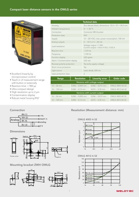
<strong>Compact</strong> <strong>laser</strong> <strong>distance</strong> <strong>sensors</strong> <strong>in</strong> <strong>the</strong> <strong>OWLG</strong> series<br />
• Excellent l<strong>in</strong>earity by<br />
microprocessor control<br />
• Teach-<strong>in</strong> of measurement range<br />
with button or externally<br />
• Reaction time: < 900 μs<br />
• Ultra compact design<br />
• High resolution up to 2 μm<br />
• Contam<strong>in</strong>ation display<br />
• Robust metal hous<strong>in</strong>g IP67<br />
Hous<strong>in</strong>g<br />
Technical data<br />
Ambient temperature 0 ~ + 50 ºC<br />
Connection<br />
Protection class<br />
Supply<br />
Analog outputs<br />
Z<strong>in</strong>c diecast black; dimensions: 12,4 × 37 × 34,5 mm<br />
Connector M8 (4 poles)<br />
IP67<br />
12 ~ 28 V DC; max. power consumption: 100 mA<br />
0 ~ 10 V or 4 ~ 20 mA<br />
Load resistance<br />
Voltage output > 1 MΩ<br />
Current output < (Vs-6 V DC) / 0.02 A<br />
Reaction time<br />
< 0,9 ms<br />
Frequency<br />
1.100 Hz<br />
Function display<br />
LED green<br />
Alarm-/ Contam<strong>in</strong>ation display LED red<br />
Reversal polarity protection Yes (only supply voltage)<br />
Short circuit protection<br />
Yes<br />
Light source<br />
Laser diode, 650 nm<br />
Laser protection class 2<br />
Range Resolution L<strong>in</strong>earity error Order code<br />
Versions with voltage output<br />
16 ~ 26 mm 0,002 ~ 0,005 mm 0,006 ~ 0,015 mm <strong>OWLG</strong> 4003 AA S2<br />
16 ~ 120 mm 0,002 ~ 0,12 mm 0,015 ~ 0,35 mm <strong>OWLG</strong> 4012 AA S2<br />
Versions with current output<br />
16 ~ 26 mm 0,002 ~ 0,005 mm 0,006 ~ 0,015 mm <strong>OWLG</strong> 4003 AE S2<br />
16 ~ 120 mm 0,002 ~ 0,12 mm 0,015 ~ 0,35 mm <strong>OWLG</strong> 4012 AE S2<br />
Connection<br />
Resolution (Measurement <strong>distance</strong>: mm)<br />
Analog<br />
BN (1)<br />
WH (2)<br />
BK (4)<br />
BU (3)<br />
Z<br />
+Vs<br />
teach <strong>in</strong><br />
analog<br />
0 V<br />
<strong>OWLG</strong> 4003 A S2<br />
6<br />
MB 10 mm<br />
5<br />
Dimensions<br />
Teach-<strong>in</strong><br />
12, 4<br />
*Emitter achsis<br />
11, 2 19 3, 9<br />
M8 x 1 2, 2<br />
34, 5<br />
31, 6<br />
LE D<br />
3 2<br />
26<br />
3, 2<br />
* 10, 6<br />
37<br />
LED<br />
Teach-<strong>in</strong><br />
4<br />
12,<br />
Resolution (µm)<br />
4<br />
MB 8 mm<br />
3<br />
MB 6 mm<br />
2<br />
MB
<strong>Compact</strong> <strong>laser</strong> <strong>distance</strong> <strong>sensors</strong> <strong>in</strong> <strong>the</strong> <strong>OWLG</strong> series<br />
Teach-<strong>in</strong>-procedure<br />
With <strong>the</strong> teach-<strong>in</strong>-fuction <strong>the</strong> borders of <strong>the</strong> measurement range can be def<strong>in</strong>ed freely with<strong>in</strong> <strong>the</strong> limits of <strong>the</strong> <strong>sensors</strong><br />
scann<strong>in</strong>g range. Thus <strong>the</strong> analogue output gets a new characterisitc curve. The teach-<strong>in</strong>-procedure (decription on<br />
page 2) can be accomplished manually with <strong>the</strong> bulit-<strong>in</strong> teach-button or equivalently by a teach-wire.<br />
With<strong>in</strong> 5 m<strong>in</strong>utes after power on <strong>the</strong> sensor can be teached with <strong>the</strong> help of <strong>the</strong> button at <strong>the</strong> sensor. After 5 m<strong>in</strong>utes<br />
<strong>the</strong> sensor does not react any longer to <strong>the</strong> button.<br />
1. Press button, <strong>the</strong> LED turns on, if <strong>the</strong> sensor can still be teached<br />
2. Press <strong>the</strong> button fur<strong>the</strong>r 5 s until <strong>the</strong> LED beg<strong>in</strong>s to flash<br />
3. Release button<br />
4. Place a target <strong>in</strong> a position where <strong>the</strong> sensor should produce 0 V or 4 mA<br />
5. Press button briefly (as a confirmation <strong>the</strong> LED flashes quickly), afterwards it cont<strong>in</strong>ues to flash normally<br />
6. Place a target <strong>in</strong> a position where <strong>the</strong> sensor should produce 10 V or 20 mA<br />
7. Press button briefly (as a confirmation <strong>the</strong> LED flashes quickly), afterwards it turns of and flashes aga<strong>in</strong> briefly.<br />
The sensor is now aga<strong>in</strong> ready for use.<br />
If one of <strong>the</strong> 2 positions was outside of <strong>the</strong> measur<strong>in</strong>g range, or if <strong>the</strong>y were to closely toge<strong>the</strong>r, <strong>the</strong> LED beg<strong>in</strong>s to<br />
flash fastly. The teach-<strong>in</strong> procedure was not successful and has to be repeated. The external teach-<strong>in</strong> works equivalently<br />
to <strong>the</strong> manual teach-<strong>in</strong> by apply<strong>in</strong>g + Vs to p<strong>in</strong> 2 (teach-<strong>in</strong>). By <strong>the</strong> teach-<strong>in</strong>-wire <strong>the</strong> <strong>sensors</strong> can be teached<br />
any time without limit.<br />
Reset to factory sett<strong>in</strong>gs<br />
1. Push <strong>the</strong> button. The red LED will turn on, if <strong>the</strong> sensor can be taught.<br />
2. Hold down <strong>the</strong> button fur<strong>the</strong>r 5 seconds. The LED will start to bl<strong>in</strong>k. DO NOT RELEASE <strong>the</strong> button now. Wait for<br />
ano<strong>the</strong>r 10 seconds. until <strong>the</strong> LED is ON without bl<strong>in</strong>k<strong>in</strong>g.<br />
3. Release button<br />
Procedere can be carried out by <strong>the</strong> teachwire also.<br />
Notes for user<br />
• The <strong>in</strong>tened use of <strong>the</strong> devices is discribed <strong>in</strong> <strong>the</strong> document. O<strong>the</strong>rs than<br />
<strong>the</strong> described uses are not permitted or only after consulation with <strong>the</strong> manufacturer.<br />
In particular <strong>the</strong> use of <strong>the</strong> devices is not permitted <strong>in</strong> applications,<br />
<strong>in</strong> which security of persons depends on <strong>the</strong> function of <strong>the</strong> devices.<br />
• The <strong>in</strong>stallation, start-up and <strong>the</strong> operation of <strong>the</strong> devices must be<br />
made by a tra<strong>in</strong>ed specialist. Here <strong>the</strong> valid regulations are relative to<br />
consider:Accident prevention, Electromagnetic compatibility<br />
• The technical data of electronics, <strong>in</strong> particular <strong>the</strong> ambient conditions and<br />
connected loads, have to be considered.<br />
Zum Hagenbach 7 • D-48366 Laer<br />
www.welotec.com • <strong>in</strong>fo@welotec.com<br />
Fon: +49 (0)2554/9130-00 • Fax: +49 (0)2554/9130-10<br />
<strong>Welotec</strong> is us<strong>in</strong>g a ISO 9001:2008 certified quality management system • All specifications are subject to change<br />
2<br />
Accessories<br />
Connection cables for M8-connector<br />
2m - straight plug,<br />
4 poles<br />
2m - right angle plug,<br />
4 poles<br />
5m - straight plug,<br />
4 poles<br />
5m - right angle plug,<br />
4 poles<br />
ZWK D08 GK24<br />
ZWK D08 WK24<br />
ZWK D08 GK54<br />
ZWK D08 WK54<br />
CAT-<strong>OWLG</strong>-V4-EN ed. 12/12 <strong>Welotec</strong> <strong>GmbH</strong>