Operating Manual Hopper loader
Operating Manual Hopper loader Operating Manual Hopper loader
9 Maintenance and repair Adjusting proximity switch (METRO H** only) METRO 0.5 to 1.5 Note Make sure that no parts fall into the unit. Cover the opening of the machine and bin. Unscrew the M6 hexagon-headed screw [7]. Using a forked wrench (WAF 9), push against the contact surface of the piston rod [4]. Press the spacer rod [3] back manually and pull the sealing disk [5] out. Remove the spring [8]. Slacken the hexagon nut [1] on the pneumatic cylinder [11]. Unscrew the pneumatic cylinder [11] and remove the implosion valve [2]. Loosen the spacer rod with forked wrench (WAF 9). Using a forked wrench (WAF 9), push against the contact surface of the piston rod [10]. Unscrew the spacer rod [3]. Installation Assemble in reverse order. Make sure that the sealing disk [5] contacts the seal [6] after assembly. Lock the thread of the piston rod [9] with Loctite 270 and the hexagon-headed screw [7] with Loctite 242. 9.6 Adjusting proximity switch (METRO H** only) 2 1 Fig. 9.7 – Adjusting proximity switch [1] Proximity switch [2] Hexagon nuts Prepare the hopper loader for maintenance (see "Before starting work" on Page 32). Close the discharge flap. Set the clearance as shown in the diagram 9.7. Lock the proximity switch [1] with the hexagon nuts [2]. 38 Edition: November 2005
METRO 0.5 to 1.5 Maintenance and repair 9 Adjusting discharge flap (METRO H** only) 9.7 Adjusting discharge flap (METRO H** only) Fig. 9.8 – Positioning weight [1] Weight Slide the weight on to the tension pin and fix the weight. Installation position: see diagram 9.8. Tighten the set screw and lock it with Loctite 242. Fig. 9.9 – Adjusting discharge flap [1] Spring-loaded thrust pad [2] Discharge flap [3] Discharge Screw the spring-loaded thrust pad [1] (see figure 9.9) up until the gap between the discharge [3] and the discharge flap [2] is 5-8 mm. Note The air gap at the discharge flap ensures that particles of granulate on the discharge flap are sucked in by the vacuum at the start of transport. The discharge flap is pulled up by the vacuum and forms an airtight seal. Edition: November 2005 39
- Page 1 and 2: Hopper loader METRO 0.5 to 1.5 Oper
- Page 3 and 4: METRO 0.5 to 1.5 Technical specific
- Page 5 and 6: METRO 0.5 to 1.5 Technical specific
- Page 7 and 8: 4 Transport and setup Connections M
- Page 9 and 10: 4 Transport and setup Connections M
- Page 11 and 12: 5 Structure and function Function M
- Page 13 and 14: METRO 0.5 to 1.5 Maintenance and re
- Page 15: METRO 0.5 to 1.5 Maintenance and re
- Page 19 and 20: 11 Option Implosion filter option M
- Page 21 and 22: METRO 0.5 to 1.5 Appendix 12 METRO
- Page 23 and 24: METRO 0.5 to 1.5 Appendix 12 METRO
- Page 25 and 26: METRO 0.5 to 1.5 Appendix 12 Multif
- Page 27 and 28: 12 Appendix Multifunction panel MET
- Page 29 and 30: A B C D E 2 A1 +ZSW PE + 24V M VACV
- Page 31: A B C D E 2 3 4 5 6 7 8 A1 +ZSW PE
9 Maintenance and repair<br />
Adjusting proximity switch (METRO H** only) METRO 0.5 to 1.5<br />
Note<br />
Make sure that no parts fall into the unit.<br />
Cover the opening of the machine and bin.<br />
Unscrew the M6 hexagon-headed screw [7]. Using a forked wrench (WAF 9), push against the<br />
contact surface of the piston rod [4].<br />
Press the spacer rod [3] back manually and pull the sealing disk [5] out.<br />
Remove the spring [8].<br />
Slacken the hexagon nut [1] on the pneumatic cylinder [11].<br />
Unscrew the pneumatic cylinder [11] and remove the implosion valve [2].<br />
Loosen the spacer rod with forked wrench (WAF 9). Using a forked wrench (WAF 9), push against<br />
the contact surface of the piston rod [10].<br />
Unscrew the spacer rod [3].<br />
Installation<br />
Assemble in reverse order.<br />
Make sure that the sealing disk [5] contacts the seal [6] after assembly.<br />
Lock the thread of the piston rod [9] with Loctite 270 and the hexagon-headed screw [7] with Loctite<br />
242.<br />
9.6 Adjusting proximity switch (METRO H** only)<br />
2<br />
1<br />
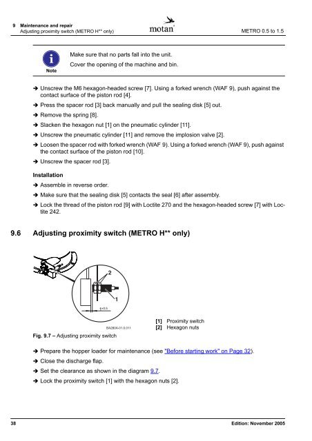
Fig. 9.7 – Adjusting proximity switch<br />
[1] Proximity switch<br />
[2] Hexagon nuts<br />
Prepare the hopper <strong>loader</strong> for maintenance (see "Before starting work" on Page 32).<br />
Close the discharge flap.<br />
Set the clearance as shown in the diagram 9.7.<br />
Lock the proximity switch [1] with the hexagon nuts [2].<br />
38 Edition: November 2005


