Create successful ePaper yourself
Turn your PDF publications into a flip-book with our unique Google optimized e-Paper software.
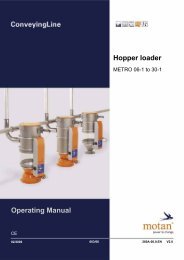
METRO 0.5 to 1.5<br />
Structure and function 5<br />
Function<br />
5 Structure and function<br />
Fig. 5.1 – Layout of the hopper <strong>loader</strong>s<br />
[1] Unit cover<br />
[2] Implosion module<br />
[3] Material inlet module<br />
[4] Multifunction panel METRO *C/J*<br />
[5] Glass/stainless steel<br />
[6] Material discharge module (bin <strong>loader</strong>)<br />
[7] Proximity switch (METRO H** only)<br />
[8] Multifunction panel METRO *P*<br />
[9] Material discharge module (machine hopper<br />
<strong>loader</strong>)<br />
[10] Demand probe (METRO M** only)<br />
5.1 Function<br />
In a hopper <strong>loader</strong> system with METRO H** and/or METRO M** hopper <strong>loader</strong>s one central Motan<br />
controller controls all units in the system.<br />
The different hopper <strong>loader</strong>s report a material requirement to the relevant controller and are then<br />
processed in succession.<br />
METRO H**: Material required via the Proximity switch if the discharge flap is closed<br />
METRO M**: Material required via the demand probe if the granulate no longer covers the demand<br />
probe.<br />
If material is required by one or more hopper <strong>loader</strong>s, the blower station starts and generates<br />
underpressure in the vacuum line. The bypass valve on the filter closes and simultaneously open the<br />
vacuum valve in the hopper <strong>loader</strong>. An underpressure forms in the vacuum line and continues<br />
through the hopper <strong>loader</strong> to the material line through to the suction point.<br />
Edition: November 2005 21