You also want an ePaper? Increase the reach of your titles
YUMPU automatically turns print PDFs into web optimized ePapers that Google loves.
<strong>TempLine</strong><br />
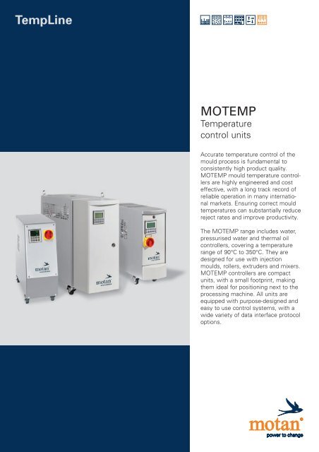
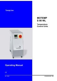
<strong>MOTEMP</strong><br />
Temperature<br />
control units<br />
Accurate temperature control of the<br />
mould process is fundamental to<br />
consistently high product quality.<br />
<strong>MOTEMP</strong> mould temperature controllers<br />
are highly engineered and cost<br />
effective, with a long track record of<br />
reliable operation in many international<br />
markets. Ensuring correct mould<br />
temperatures can substantially reduce<br />
reject rates and improve productivity.<br />
The <strong>MOTEMP</strong> range includes water,<br />
pressurised water and thermal oil<br />
controllers, covering a temperature<br />
range of 90°C to 350°C. They are<br />
designed for use with injection<br />
moulds, rollers, extruders and mixers.<br />
<strong>MOTEMP</strong> controllers are compact<br />
units, with a small footprint, making<br />
them ideal for positioning next to the<br />
processing machine. All units are<br />
equipped with purpose-designed and<br />
easy to use control systems, with a<br />
wide variety of data interface protocol<br />
options.
"smart solutions" is an additional range<br />
of equipment for optimising and automating<br />
the production around plastics processing<br />
machines.<br />
smart solutions: to increase productivity with the<br />
least capital expenditure.<br />
All units can be combined or expanded in<br />
order to satisfy increasing and changing<br />
requirements. "smart solutions" help<br />
the plastics processor to equip their individual<br />
machines or production cells. In<br />
the case of injection moulding, extrusion<br />
or blow moulding machines, cost savings<br />
can be easily achieved with minimum<br />
outlay.<br />
Individual applications and problems are<br />
rapidly solved and may be the first steps<br />
towards a later system solution. "smart<br />
solutions" correspond to Motan's high<br />
quality standard in spite of lower prices<br />
and are available through Motan's worldwide<br />
distribution and service network. All<br />
units may of course be integrated into<br />
system solutions.<br />
• Material bins for clean and clearly arranged<br />
material storage<br />
• Dryers for energy saving material drying<br />
to a defined residual moisture, or removing<br />
surface moisture and preheating of<br />
material<br />
• Conveying equipment for automatic<br />
material transport and supply to the<br />
machine<br />
• Dosing and mixing units for self colouring<br />
or addition of additives and regrind<br />
• Mobile granulators for sprues and rejects<br />
as well as the introduction of regrind to<br />
the material flow<br />
• Temperature control units to maintain the<br />
temperature for optimum conditioning of<br />
injection moulds<br />
Examples for step-by-step automation of injection moulding machines.
1. Hopper loader for automatic machine feeding<br />
2. Material storage bin<br />
3. Debagging station<br />
4. <strong>MOTEMP</strong>, mould temperature control<br />
5. Granulators for granulating sprues with material recirculation<br />
6. MINICOLOR V, volumetric colouring unit<br />
7. MINICOLOR G, gravimetric colouring unit<br />
8. GRAVICOLOR, dosing and mixing unit<br />
9. LUXOR HD, hot air dryer<br />
10. LUXOR CA, compressed air dryer<br />
11. LUXOR, dry air dryer<br />
12. Blower station<br />
13. Central blower station with filter
Temperature control units<br />
For water up to 90°C<br />
or thermal oil up to 150°C<br />
Temperature control of injection<br />
moulds, extruders, rollers and<br />
storage tanks.<br />
Further advantages:<br />
Minimal reject rates beginning at production<br />
start-up. Better cavity-filling<br />
behaviour. Closer tolerances. Minimum<br />
warping and shrinkage. Better surface<br />
finish. Continuous high-quality production.<br />
In the manufacture of injection moulded<br />
parts, correct mould temperatures<br />
– ensured by Motan temperature control<br />
units – can reduce reject rates by<br />
24% and improve productivity by up to<br />
20% (Research report by the Aachen<br />
Technical University/Germany).<br />
Small-unit assembly: From standard units to special<br />
designs, Motan offers customised solutions.<br />
4
Standard equipment<br />
• RT32 controller or RT50 control system.<br />
➝ Optimal fit for practically every application.<br />
For technical data see page 16.<br />
S 90 WL and S 150 OL: control system<br />
RT60.<br />
• All components exposed to water are made<br />
of stainless steel (tank and cover) or nonferrous<br />
materials ➝ Long service life.<br />
• Filter in cooling water inlet.<br />
• Acoustic alarm (buzzer). A 150 BL optional.<br />
• Automatic water refilling (water units).<br />
A 150 BL optional.<br />
• High-performance leak-free centrifugal and<br />
pump motor for circulation of the thermal<br />
oil even at low temperatures ➝ Safe operation.<br />
• Low thermal load of the fluid, short circulating<br />
time ➝ Long service life of the heat<br />
transfer oil, good control of temperature.<br />
• Specially-treated heater elements for high<br />
corrosion resistance ➝ Safe operation, long<br />
service life.<br />
• A 90 WLX with direct cooling (DK) › High<br />
efficiency, high cooling capacity.<br />
• Adjustable internal bypass (A 90 WLX)<br />
➝ Better control of temperature.<br />
• Manual shut off valve in the inlet and outlet<br />
(model A 90 WLX ).<br />
• Safety thermostat ➝ Protection against<br />
overheating.<br />
• Automatic fluid level control<br />
➝ Protection against running dry.<br />
• Fail-safe circuit in case of heat contactor<br />
malfunction. Current to the heater is interrupted<br />
by an overriding main contactor<br />
➝ Protection against overheating of unit.<br />
• Suction and leak-stop operation standard<br />
for units S 90 WL, S 150 OL and units with<br />
RT32 controller. A 90 WLX not possible.<br />
• Electric control in accordance with IEC<br />
standards. Degree of protection IP40.<br />
A 90 WLX IP54. Tropic-proof up to 90%<br />
humidity. Completely separated from the<br />
pumping section and protected against<br />
direct contact ➝ Safe operation.<br />
• In accordance with the following standards:<br />
– Machine Guidelines 98/37/EU.<br />
– Guidelines Electro-Magnetic Compatibility<br />
89/336/EG.<br />
– Low voltage standards 73/23/EU.<br />
– Electrical equipement of industrial<br />
machines EN 60204-1, 1997<br />
– Low voltage switchgear and controlgear<br />
assemblies. Part 1. EN 60439-1, 1999.<br />
Optional equipment<br />
• Solid-state relay (SSR) instead of heating contactor.<br />
S 90 WL and S 150 OL standard.<br />
• A 90 WLX Blow out with manual valve.<br />
Further options see control system<br />
RT50 and RT60, page 16<br />
Unit selection<br />
• For help on selecting the right unit please see<br />
page 27.<br />
5
Technical data S 90 WL A 90 WL A 90 WLX S 150 OL A 150 OL A 150 BL<br />
Outlet temperature max. °C 90 90 90 150 150* 90 150**<br />
Heat transfer fluid Water Water Water Oil Oil Water Oil<br />
Filing quantity l 6.5 6.0 36.5 12.0 12.0 17.6 17.6<br />
Expansion volume max. l 3.2 3.4 5.5 4 4 6 6<br />
Heating capacity at 400 V kW 9 6; 9 20; 40; 60 6 6 12; 18 12<br />
Cooling capacity kW 24 76 38 58 160 28 31 28 50 70 58 70<br />
at outlet temperature °C 90 90 80 80 80 140 90 140 80 40 140 60<br />
Cooler (K) 1 2 1 2 DK 1 1 1 1 2 1 2<br />
Diagram (Fig.) 1 1 3 5 1 5 1 5<br />
Pump capacity/type TP20 TP20 TS22 IMZ-G TP20 TP20 TS22 TP20 TS22<br />
Flow rate max. l/min 60 60 70 240 60 60 70 60 70<br />
Pressure max. bar 3.8 3.8 5.4 4.6 3.8 3.8 5.4 3.8 5.4<br />
Power consumption kW 0.5 0.5 1.1 2.2 0.5 0.5 1.1 0.5 1.1<br />
Diagram (Fig.) 2 2 4 2 2 2 2<br />
Control RT60 RT32 RT50 RT32*** RT50 RT60 RT32*** RT50 RT32 RT50<br />
Measuring mode (standard) Pt100 Pt100 Pt100 Pt100 Pt100 Pt100<br />
Operating voltage (standard) V/Hz 400/50, 3 PE 400/50, 3 PE 400/50, 3 PE 400/50, 3 PE 400/50, 3 PE 400/50, 3 PE<br />
Connections<br />
Outlet/inlet G 1 ⁄2” G 1 ⁄2” G1 1 ⁄2” IG G 1 ⁄2” G 1 ⁄2” M 26 x 1,5<br />
Cooling water mains G 3 ⁄8” G 1 ⁄2” G 3 ⁄4” G 3 ⁄8” G 1 ⁄2” G 1 ⁄2”<br />
Dimensions W/H/D mm 220/568/610 220/552/670 422/1352/1370 230/615/705 200/648/700 346/690/728<br />
Weight approx. kg 32 44 229 41 50 78<br />
Colour Grey RAL 9006/7016<br />
Ambient temperature max. °C 40<br />
Noise level dB (A)
Cooling capacity (continued)<br />
Pump capacity (continued)<br />
831.001a<br />
9.001650<br />
9.001654A<br />
Fig. 3: Fluid water; A 90 WLX<br />
Fig. 4: A 90 WLX<br />
Fig. 5: Fluid thermal oil S 150 OL; A 150 OL; A 150 BL<br />
Fig. 6: Principle A 90 WL<br />
Fig. 8: Principle A 90 WLX<br />
16 16<br />
9.000471 828.001a<br />
Fig. 7: Principle S 90 WL; S 150 OL;<br />
A 150 BL Water<br />
Fig. 9: Principle S 150 OL; A 150 OL; A 150 BL Oil<br />
804.004b<br />
831.003a<br />
1 Cooler<br />
2 Heater<br />
3 Pump<br />
4 Solenoid valve, cooling<br />
5 Temperature sensor<br />
6 Level control<br />
7 Safety thermostat<br />
8 Tank<br />
9 Filter, cooling water inlet<br />
10 Solenoid valve, consumer<br />
drainage (optional<br />
with control system<br />
RT50)<br />
11 Solenoid valve, automatic<br />
water refilling<br />
(A 150 BL optional)<br />
12 One-way check valve<br />
13 Bypass<br />
14 Pressure gauge<br />
15 Manual valve<br />
16 Consumer<br />
7
Pressurised-water<br />
temperature control<br />
units up to 160°C.<br />
Temperature control of plastic injection<br />
moulds, die-casting dies, rollers,<br />
extruders, mixers, vessels...<br />
Superior heat transfer has a direct effect<br />
upon the output of your production<br />
plant.<br />
Pressurised water units can be implemented<br />
wherever there are advantages<br />
of water as a heat transfer fluid.<br />
Patented low-scale cooling system “SK”.<br />
Quality assurance: At Motan, all units, whether standard<br />
or customised, undergo all phases of rigorous<br />
final testing.<br />
8
Standard equipment<br />
• RT32 controller or RT50 control system.<br />
➝ Perfect for almost every application.<br />
S 140 WN: control system RT60. For technical<br />
data see page 16.<br />
• Operating temperature independent of<br />
cooling water pressure ➝ Flexible operation.<br />
• A 140 WPX, A 160 WPX with special patented<br />
“SK” cooling system prevents lime<br />
scale buildup.<br />
• All components exposed to water are made<br />
of non-ferrous materials ➝ Long service<br />
life.<br />
• Automatic fluid level control<br />
➝ Protection against running dry.<br />
• Safety valve ➝ Prevents excessive pressure<br />
in the unit.<br />
• Safety thermostat ➝ Protection against<br />
overheating.<br />
• Fail-safe over all mains contactor<br />
➝ Protection against overheating of the<br />
unit.<br />
• Sturdy and powerful centrifugal pump with<br />
maintenance-free rotating mechanical seal.<br />
Pump with special coating for corrosion<br />
resistance ➝ Long service life.<br />
• A 160 WP (D), A 160 WPX pump with<br />
magnetic drive (S 140 WN, A 140 WN,<br />
A 140 WP, A 140 WPX optional) ➝ Leakfree<br />
operation (no mechanical seal).<br />
• Specially-treated heating elements for greater<br />
corrosion resistance<br />
➝ Safe operation, long service life.<br />
• One-way check valve in cooling water outlet<br />
➝ Eliminates the possibility of scale in the<br />
cooler by back-flow water.<br />
• Automatic water refill.<br />
• Filter in cooling water inlet.<br />
• A 140 WPX, A 160 WPX: Pressure gauge<br />
for system pressure and outlet pressure<br />
indication.<br />
• Ball valve in the inlet and outlet (A 140<br />
WPX, A 160 WPX).<br />
• Acoustic alarm (buzzer).<br />
• Small filling quantity and high pump capacity<br />
➝ Quick compensation of disturbances,<br />
good regulating behaviour, economical operation.<br />
• Adjustable internal bypass.<br />
(A 140 WPX, A 160 WPX).<br />
• Electric control in accordance with IEC<br />
standards. Degree of protection IP40. A<br />
140 WPX, A 160 WPX, IP54. Tropic-proof<br />
up to 90% humidity. Completely separated<br />
from the pumping section and protected<br />
against direct contact ➝ Safe operation.<br />
• In accordance with the following standards:<br />
– Machine Guidelines 98/37/EU.<br />
– Pressurised Units 97/37/EU.<br />
– Guidelines Electro-Magnetic Compatibility<br />
89/336/EG.<br />
– Low voltage standards 73/23/EU.<br />
– Electrical equipment of industrial<br />
machines EN 60204-1, 1997.<br />
– Low voltage switchgear and controlgear<br />
assemblies. Part 1. EN 60439-1, 1999.<br />
Optional equipment<br />
• A 140 WP and A 160 WP (D) with patented<br />
“SK” cooling system prevents lime<br />
scale build up.<br />
• A 140 WN and A 140 WP with direct cooling<br />
for low consumer temperatures.<br />
• Solid-state relay (SSR) in place of heating<br />
contactor. S 140 WN standard.<br />
• Temperature regulated switchover indirect<br />
to direct cooling (only with RT50).<br />
Further options see control systems<br />
RT50 and RT60 page 16.<br />
Unit selection<br />
• For help on selecting the right unit please<br />
see page 27.<br />
9
Technical data S 140 WN A 140 WN A 140 WP A 140 WPX A 160 WP(D) A 160 WPX<br />
Outlet temperature max. °C 140 140 140 140 160 160<br />
Heat transfer fluid Water Water Water Water Water Water<br />
Filling quantity l 4 1 6.5 36.5 6.5* 36,5<br />
Expansion volume max. l 0.5 – 3.5 14.5 3.5* 14,5<br />
Heating capacity at 400 V kW 9 6 9; 12 20; 40; 60 9; 12* 20; 40; 60<br />
Cooling capacity type kW 35 35 35 43 110 43* 43* 135<br />
at outlet temperature °C 130 130 130 90 130 150 90 150<br />
Cooler (K) 1 1 1 2; SK SK 1 2; SK SK<br />
Diagram (Fig.) 1 1 1 1 3 1 1 3<br />
Pump capacity/type B501 SM51 B501 SM20 SG51 SM51 IMZ-G SM51 IMZ-M<br />
Flow rate max. l/min 45 45 45 27 45 45 240 45* 240<br />
Pressure max. bar 6.0 7,0 6.0 4.5 6.0 7.0 4.6 7.0* 4.6<br />
Power consumption kW 0.85 1,0 0.85 0.5 0.75 1.0 2.2 1.0* 2.2<br />
Diagram (Fig.) 2 2 2 4 2 4<br />
Control RT60 RT32 RT50 RT32 RT50 RT50 RT50 RT50<br />
Measuring mode (standard) Pt100 Pt100 Pt100 Pt100 Pt100 Pt100<br />
Operating voltage (standard) V/Hz 400/50, 3 PE 400/50, 3 PE 400/50, 3 PE 400/50, 3 PE 400/50, 3 PE 400/50, 3 PE<br />
Connections<br />
Outlet/inlet G 1 ⁄2” G 1 ⁄2” G 1 ⁄2” G 1 1 ⁄2” IG G 1 ⁄2” G 1 1 ⁄2” IG<br />
Cooling water mains G 3 ⁄8” G 1 ⁄2” G 1 ⁄2” G 3 ⁄4” G 1 ⁄2” G 3 ⁄4”** G 3 ⁄4”<br />
Dimensions W/H/D mm 230/615/705 200/552/670 320/756/830 422/1352/1370 320/756/830 422/1352/1570<br />
460/1446/910**<br />
Weight approx. kg 45 45 75 275 80/160** 275<br />
Colour Grey RAL 9006/7016<br />
Ambient temperature max. °C 40<br />
Noise level dB (A) < 70<br />
Notes * Per Zone G: Parallel thread<br />
** Dual Zone unit (D) IG: Female thread<br />
Cooling capacity P as a function of<br />
outlet temperature ϑ.<br />
Cooling water data:<br />
Inlet temperature +20 °C.<br />
Flow rates<br />
S 140 WN; A 140 WN; A 140 WP ;<br />
A 160 WP(D)<br />
with 1K:<br />
10 l/min.<br />
with 2K; SK:<br />
20 l/min.<br />
A 140 WPX; A 160 WPX; with SK: 35 l/min.<br />
Pump capacity. Flow rate V<br />
as a function of pressure p.<br />
Bypass not included.<br />
814.029g<br />
814.054c<br />
Fig. 1: S 140 WN; A 140 WN; A 140 WP; A 160 WP(D)<br />
Fig. 2: S 140 WN; A 140 WN; A 140 WP; A 160 WP(D)<br />
10
Cooling capacity (continued)<br />
Pump capacity (continued)<br />
9.001134A<br />
9.001654<br />
Fig. 3: A 140 WPX; A 160 WPX<br />
Fig. 4: A 140 WPX; A 160 WPX<br />
Fig. 5: Principle S 140 WN<br />
Fig. 7: Principle A 140 WP, A 160 WP(D)<br />
9.002154A<br />
9.003381 836.001c<br />
Fig. 6: Principle A 140 WN<br />
Fig. 8: Principle A 140 WP, A 160 WP(D)<br />
with cooler SK<br />
836.002D 808.009F<br />
1 Cooler<br />
2 Heater<br />
3 Pump<br />
4 Solenoid valve, automatic<br />
water refilling<br />
5 Solenoid valve, cooling<br />
6 Solenoid valve, pressure<br />
release<br />
7 Temperature sensor<br />
8 Safety valve<br />
9 One way check-valve<br />
10 Filter, cooling water inlet<br />
11 Level control<br />
12 Expansion valve<br />
13 Safety thermostat<br />
14 Pressure gauge<br />
15 Filling pump<br />
(A 160 WP[D]; A 160 WPX).<br />
A 140 WP; A 140 WPX<br />
optional<br />
16 Cooling pump (cooler SK)<br />
17 Solenoid valve, consumer<br />
drainage (optional)<br />
18 System (tank)<br />
19 Thermal cut-off<br />
20 Blow out solenoid valve<br />
(optional)<br />
21 Pressure reducing valve<br />
22 Bypass<br />
23 Shut-off valve<br />
24 – –<br />
25 Expansion vessel<br />
26 – –<br />
27 Consumer<br />
Fig. 9: Principle A 140 WPX; A 160 WPX with cooler SK<br />
11
Temperature control units<br />
for thermal oil<br />
up to 350°C.<br />
Temperature control of die-casting<br />
dies, shot-sleeves, extruders, rollers,<br />
storage tanks, mixers, vessels...<br />
Motan temperature control units can<br />
reduce reject rates up to 80%, and<br />
make the die last up to 3 times longer,<br />
reducing heat-up time by as much as<br />
30%<br />
Mechanical assembly:<br />
Expertise and precision assure the high quality of<br />
our products.<br />
12
Standard equipment<br />
• RT50 control system ➝ Perfect fit for<br />
almost every application. For technical data<br />
see page 16.<br />
• Pump with magnetic drive ➝ Leak-free<br />
operation.<br />
• A 300 OLX(D) with solid-state relays (SSR).<br />
• Dual zone (D) ➝ Small foot print.<br />
• Pressure gauge in the outlet and inlet.<br />
• One-way check valve in cooling water outlet<br />
➝ Less scaling in the cooler by back<br />
flow water.<br />
• Automatic fluid level control ➝ Protection<br />
against running dry. A 300 OLX(D) with two<br />
level switches (empty + prewarning).<br />
• Flow monitor ➝ Protection against running<br />
dry and overheating of the oil.<br />
• Separate expansion vessel ➝ Reduces oxidation<br />
(coking or degradation). Emission of<br />
combustible oils into the atmosphere is<br />
avoided.<br />
• Bypass for internal circulation of the oil in<br />
case of insufficient flow, e.g. when the<br />
consumer is blocked ➝ Avoids thermal<br />
overloading of the oil.<br />
• A 350 OLX: Cooler with bypass circuit (Fig.<br />
5)<br />
➝ Much better regulating behaviour,<br />
reduced tendency from lime scale.<br />
• Safety thermostat ➝ Protection against<br />
overheating.<br />
• Filter in cooling water inlet.<br />
• Small filling quantity and high pump capacity<br />
➝ Quick compensation of disturbances,<br />
good control behaviour.<br />
• Fail-safe over all mains contactor<br />
➝ Protection against overheating of unit.<br />
• Acoustic alarm (buzzer).<br />
• Electric control in accordance with IEC<br />
standards. Degree of protection IP40. A<br />
300 OLX(D) IP54. Tropic-proof up to 90%<br />
humidity. Completely separated from the<br />
pumping section and protected against<br />
direct contact ➝ Safe operation.<br />
• In accordance with the following standards:<br />
– Machine Guidelines 98/37/EU.<br />
– Pressurised Units 97/37/EU.<br />
– Guidelines Electro-Magnetic Compatibility<br />
89/336/EG<br />
– Low voltage standards 73/23/EU.<br />
– Electrical equipment of industrial<br />
machines EN 60204-1, 1997.<br />
– Low voltage switchgear and controlgear<br />
assemblies. Part 1. EN 60439-1, 1999.<br />
Optional equipment<br />
• A 300 OL; A 350 OLX Solid-state relay<br />
(SSR) instead of heating contactor.<br />
A 300 OLX(D) standard<br />
• A 350 OLX with inert gas blanke<br />
➝ Longer oil life.<br />
• Flow measurement F350.<br />
• A 300 OLX(D): Cooler with bypass circuit.<br />
Further options see control system<br />
RT50, page 16.<br />
Unit selection<br />
• For help on selecting the right unit please<br />
see page 27.<br />
13
Technical data A 300 OL A 300 OLX(D) A 350 OLX<br />
Outlet temperature max. °C 300 300 350<br />
Heat transfer fluid Thermal oil Thermal oil Thermal oil<br />
Filling quantity l 6 15 24* 15-20<br />
Expansion volume l 7 20 20<br />
Heating capacity at 400 V kW 6 20; 40** 24; 36<br />
Cooling capacity kW 70 160** 110<br />
at outlet temperature °C 280 280 340<br />
Cooler (K) 1 1* 1<br />
Diagram (Fig.) 1 1 2<br />
Pump capacity/type FM25 FM65 FM65<br />
Flow rate max. l/min 45 90** 90<br />
Pressure max. bar 7.0 10.0** 10.0<br />
Power consumption kW 1.0 2.8** 2.8<br />
Diagram (Fig.) 3 3 3<br />
Control RT50 RT50 RT50<br />
Measuring mode (standard) Pt100 Pt100 Pt100<br />
Operating voltage (standard) V/Hz 400/50, 3 PE 400/50, 3 PE 400/50, 3 PE<br />
Connections<br />
Outlet/inlet G 1 ⁄2” G 3 ⁄4” IG DN 20/PN 40<br />
Cooling water mains G 1 ⁄2” G 3 ⁄4” G 3 ⁄4”<br />
Dimensions W/H/D mm 320/756/900 422/1352/1450 470/1467/1626<br />
532/1352/1450*<br />
Weight approx. kg 87 246 310<br />
365*<br />
Colour Grey RAL 9006/7016<br />
Ambient temperature max. °C 40<br />
Noise level dB (A) < 70<br />
Notes * Dual zone unit (D) G: Parallel thread<br />
** Per zone IG: Female thread<br />
Cooling capacity P as a function<br />
of outlet temperature ϑ.<br />
Cooling water data:<br />
Inlet temperature +20 °C.<br />
Flow rate per zone 20 l/min.<br />
807.013c<br />
820.060<br />
Fig. 1: A 300 OL, A 300 OLX(D)<br />
Fig. 2: A 350 OLX<br />
14
Pump capacity. Flow rate V<br />
as a function of manometric pressure p.<br />
Bypass not included.<br />
9.002645<br />
820.058a<br />
9.003417<br />
Fig. 3: Pump capacity<br />
Fig. 4: Principle A 300 OL; A 300 OLX(D)<br />
Fig. 5: Principle A 300 OLX(D); with bypass<br />
circuit for the cooler<br />
9.002641<br />
1 Cooler<br />
2 Heater<br />
3 Pump<br />
4 Expansion vessel<br />
5 Solenoid valve, cooling<br />
6 Outlet temperature sensor<br />
7 – –<br />
8 Level control<br />
9 Safety thermostat<br />
10 Bypass<br />
11 Filter cooling water inlet<br />
12 Filter circuit (A 350 OLX option)<br />
13 – –<br />
14 Flow monitoring<br />
15 – –<br />
16 One-way check valve<br />
17 Solenoid valve, consumer drainage<br />
(optional)<br />
18 Pressure gauge<br />
19 Inlet temperature sensor (optional)<br />
20 Three-way valve (A 300 OLX[D]<br />
option)<br />
21 Solenoid valve compressed air<br />
22 Pressure reducing valve<br />
23 Diaphragm<br />
24 Consumer<br />
Fig. 6: Principle A 350 OLX with; with bypass<br />
circuit for the cooler<br />
15
RT50 and RT60 control system,<br />
controller RT32.<br />
The RT50 control system ensures an optimal<br />
fit for practically every application. The<br />
RT60 control system and the RT32 controller<br />
are a simple, cost-effective solutions<br />
for a wide variety of applications.<br />
All controllers are designed to avoid problems<br />
before they arise.<br />
Modern automated manufacturing processes<br />
require data transfer between the<br />
temperature control unit and the production<br />
facility’s central computer – just one<br />
of many applications for the RT50 and<br />
RT60 control system with data interface.<br />
RT50<br />
RT60<br />
RT32<br />
16
RT50 technical data<br />
Operation and control<br />
• Seven-line clear-text LCD display. Choice of<br />
languages.<br />
• Simultaneous readout of temperature setpoint<br />
and actual values. Choice of temperature<br />
display (decimal place).<br />
• Clear arrangement of operating and indicating<br />
elements.<br />
• Fully automatic function sequences<br />
➝ Simple to operate.<br />
• Control options:<br />
– Consumer temperature with cascade<br />
control for highest temperature constancy<br />
with 2 control circuits (consumer and fluid).<br />
– Fluid Temperature.<br />
• Set-point switch-over.<br />
Safety<br />
• All disturbances in the unit are indicated on<br />
the display.<br />
• Set-point «blockable» ➝ Protection against<br />
incorrect adjustment.<br />
• Limitation of max. programmable set-point.<br />
• Monitoring of upper and lower limit values.<br />
• Unauthorized access to the programming<br />
levels prevented by a code.<br />
• Sensor-failure monitoring.<br />
• Automatic switch-over to the internal sensor<br />
in the event of external sensor failure.<br />
• Units with automatic water refilling: In order<br />
to limit the consequences of leakage (i.e.<br />
hose burst) the filling time per refill and the<br />
number of refills per hour is limited<br />
➝ Protection of the production installation<br />
against damage caused by water.<br />
Service<br />
• Indication of the service interval.<br />
• Operating hours meter.<br />
• Programmed data remains stored during<br />
replacement of electronic components.<br />
Optional equipment<br />
• External sensor connection for Pt 100,<br />
J (Fe-CuNi), K (NiCr-Ni) or T (Cu-CuNi).<br />
• Leak-stop operation.<br />
• Drainage of the fluid from the consumer by<br />
suction/compressed air.<br />
• Common alarm.<br />
• Time switch.<br />
• Inlet sensor (Pt100).<br />
• Flow rate measurement from 2 to 50 l/min<br />
up to 350 °C.<br />
• External control: set-point input, set-point<br />
switch-over, heating/cooling command,<br />
on/off of the unit.<br />
• More than 30 interface protocols available.<br />
• Scaleable recorder output.<br />
• Automatic pump rotation correction.<br />
RT60 technical data<br />
Operation and control<br />
• Simultaneous readout of temperature setpoint<br />
and actual values.<br />
• Clear arrangement of operating and indicating<br />
elements.<br />
• Fully automatic function sequences.<br />
• Drainage of the fluid from the consumer by<br />
suction.<br />
• Common alarm.<br />
• Automatic pump rotation correction.<br />
Safety<br />
• All disturbances in the unit are indicated on<br />
the display.<br />
• Limitation of max. programmable set-point.<br />
• Monitoring of upper and lower limit values.<br />
• Unauthorized access to the programming<br />
levels prevented by a code.<br />
• Automatic pump rotation correction.<br />
• Sensor-failure monitoring.<br />
Service<br />
• Indication of the service interval.<br />
• Operating-time meter.<br />
Optional equipment<br />
• External set-point input. External on/off.<br />
• 9 interface protocols available.<br />
• Scaleable recorder output.<br />
• Flow rate measurement from 2 to 50 l/min<br />
for water and oil up to 150 °C.<br />
RT32 technical data<br />
• Clear arrangement of operating and indicating<br />
elements.<br />
• Simultaneous readout of temperature setpoint<br />
and actual values.<br />
• Sensor-failure monitoring.<br />
• Permanent self-testing of the controller.<br />
• Monitoring of upper and lower limit values<br />
for fluid temperature. Optional.<br />
17
MTA 30 descaling unit and<br />
descaling agent MD 3,<br />
corrosion inhibitor MP 5<br />
and system cleaner MC 7.<br />
With the MTA 30 descaling unit for water<br />
systems, descaling agent MD 3, corrosion<br />
inhibitor MP 5 and system cleaner<br />
MC 7 for oil circuits, Motan offers their<br />
customers optimal assistance for maintenance.<br />
Descaling unit MTA 30 and descaling<br />
agent MD 3 for cleaning of moulds and<br />
dies, cooling circuits and other systems<br />
operated with water or steam.<br />
Corrosion inhibitor MP 5 prevents corrosion,<br />
lime deposits and the formation of<br />
rust in water circuits.<br />
System cleaner MC 7 is a highly effective<br />
additive for cleaning heat transfer<br />
systems and other circuits contaminated<br />
by oil residue.<br />
At the Motan Test Center, any operating condition can<br />
be simulated and checked – under continuous testing.<br />
18
MTA 30 descaling unit<br />
• Incorporated heating ➝ Minimal cleaning<br />
time.<br />
• Simple connection to the encrusted circuit<br />
without dismantling of the installation<br />
➝ Operation without problems, time saving.<br />
• Electric control in separate housing, heater<br />
protected against running dry, tank of plastic<br />
and cover of stainless steel ➝ Safe and<br />
harmless operation.<br />
Technical data MTA 30<br />
Operating temperature<br />
Tank capacity<br />
Heating capacity<br />
Pump capacity<br />
Flow rate<br />
Delivery head<br />
Power consumption<br />
Operating voltage (standard)<br />
Connections<br />
Dimensions W/H/D<br />
Weight<br />
Colour<br />
Accessories<br />
max.<br />
max.<br />
approx.<br />
°C<br />
l<br />
kW<br />
l/min<br />
bar<br />
kW<br />
V/Hz<br />
mm<br />
kg<br />
60<br />
12<br />
0.8<br />
30<br />
1.6<br />
1.2<br />
230/50; 60, 1 PNE<br />
Nipples DN 16<br />
305/610/455<br />
13<br />
Grey<br />
2 hoses, length 2.5 m<br />
MD 3 Descaling agent<br />
• Environmentally friendly and biodegradable.<br />
• The combination of an organic acid with an<br />
inorganic activator results in a descaling<br />
agent that has the same effect as a strong<br />
acid: quickly and efficiently removes lime,<br />
scale, and rust deposits without damaging<br />
the equipment.<br />
• Also suitable for tin and enamel.<br />
• 1 kg MD 3 removes approx. 0.5 kg lime.<br />
System cleaner MC 7<br />
• The additive removes oil-carbon residues<br />
and foreign contamination from metal surfaces.<br />
They circulate in the oil flow and are<br />
carried to the filter.<br />
• The optimal cleaning effect is between<br />
120 and 150 °C.<br />
• The max. permissible operating temperature<br />
is 300 °C.<br />
• The MC 7 additive contains no solvents. It<br />
can be dissolved in all mineral oils and synthetic<br />
fluids.<br />
• Application as a preventive or before changing<br />
the oil.<br />
Corrosion inhibitor MP 5<br />
• Temperature range –10 °C to +180 °C.<br />
• The additive helps prevent: electrolytic corrosion<br />
of all metals, dezincification of brass,<br />
lime deposits and adherence of hard rust<br />
particles.<br />
• MP 5 can be mixed with GLYCOL products<br />
and does not attack seals.<br />
• Suitable for pressurised water systems.<br />
• Economical to use.<br />
• MP 5 retains its properties over an extended<br />
period and forms a protective film on the<br />
contact surfaces, providing constant efficiency<br />
of the heat exchanger.<br />
19
Motan accessories.<br />
Motan accessories cover all components<br />
for connecting the unit to the consumer,<br />
including heat transfer fluids, corrosion<br />
inhibitor and cleaners.<br />
Motan accessories: Safety between temperature<br />
control unit and consumer.<br />
Motan accessories are in exact accordance<br />
with our specifications – values that<br />
incorporate the experience gained overmany<br />
years. Choose safety.<br />
20
Fittings<br />
4. Dummy plug for hose fitting<br />
Dimensions in mm if not specified otherwise.<br />
DN = Nominal width. SW = Spanner<br />
size.*DIN 3863: tapered sealing.<br />
d*<br />
M 18 x1.5<br />
SW<br />
27<br />
Order No.<br />
305-080140<br />
1. Adapter<br />
d1*<br />
M 14 x1.5<br />
M 14 x1.5<br />
M 16 x1.5<br />
M 16 x1.5<br />
M 18 x1.5<br />
M 18 x1.5<br />
M 18 x1.5<br />
M 18 x1.5<br />
M 18 x1.5<br />
M 26 x1.5<br />
d2<br />
R 1 /2”<br />
R 3 /4”<br />
R 1 /2”<br />
R 3 /4”<br />
M 14 x1.5*<br />
M 16 x1.5*<br />
R 1 /2”<br />
R 1 /2”<br />
R 3 /4”<br />
R 3 /4”<br />
DN<br />
6<br />
6<br />
10<br />
10<br />
10<br />
10<br />
10<br />
10<br />
12<br />
16<br />
SW<br />
27<br />
32<br />
27<br />
32<br />
22<br />
22<br />
27<br />
27<br />
32<br />
32<br />
Order No.<br />
301-080114<br />
301-080118<br />
301-080113<br />
301-080117<br />
301-080115<br />
301-080112<br />
301-080110<br />
302-080108**<br />
302-080105**<br />
302-080106**<br />
5. Elbow with cap nut<br />
d*<br />
M 18 x1.5<br />
M 18 x1.5<br />
M 26 x1.5<br />
Hoses<br />
1. Fabric-reinforced perbunane/neoprene hose<br />
for water up to 70 °C and oil up to 120 °C<br />
d*<br />
M 14 x1.5<br />
M 14 x1.5<br />
M 18 x1.5<br />
M 18 x1.5<br />
DN<br />
6<br />
6<br />
10<br />
10<br />
l(m)<br />
0.6<br />
2.5<br />
0.6<br />
2.5<br />
SW<br />
17<br />
17<br />
24<br />
24<br />
Order No.<br />
362-080213<br />
362-080214<br />
362-080211<br />
362-080212<br />
3. Quick-connect coupling for Oil up to 250 °C.<br />
Special gasket. Shut-off in both directions.<br />
d1*<br />
M 18x1.5<br />
M 18x1.5<br />
M 26x1.5<br />
M 26x1.5<br />
d2<br />
40<br />
40<br />
54<br />
54<br />
DN<br />
12<br />
12<br />
15<br />
15<br />
I<br />
77<br />
78<br />
95<br />
94<br />
Description<br />
Socket<br />
Plug<br />
Socket<br />
Plug<br />
Order No.<br />
465-080330<br />
465-080331<br />
465-080332<br />
465-080333<br />
2. PTFE hose for water up to 200 °C and oil up<br />
to 250 °C. Stainless steel jacket.<br />
d*<br />
M 18 x1.5<br />
M 18 x1.5<br />
M 26 x1.5<br />
M 26 x1.5<br />
DN<br />
10<br />
10<br />
16<br />
16<br />
l(m)<br />
0.6<br />
2.5<br />
0.8<br />
2.5<br />
SW<br />
22<br />
22<br />
32<br />
32<br />
Min. permiss.<br />
bending radius<br />
120<br />
120<br />
165<br />
165<br />
Order No.<br />
362-080250<br />
362-080252<br />
362-080251<br />
362-080253<br />
80320/80322 80321/80323<br />
80330/80332 80331/80333<br />
3. All-metal hose with steel jacket. For oil up to<br />
350 °C. Without heat insulation.<br />
d*<br />
M 18 x1.5<br />
M 18 x1.5<br />
M 18 x1.5<br />
M 26 x1.5<br />
M 26 x1.5<br />
DN<br />
10<br />
10<br />
10<br />
16<br />
16<br />
l(m)<br />
0.6<br />
1.5<br />
2.5<br />
1<br />
2.5<br />
SW<br />
22<br />
22<br />
22<br />
32<br />
32<br />
Min. permiss.<br />
bending radius<br />
140<br />
140<br />
140<br />
175<br />
175<br />
Order No.<br />
362-080260<br />
362-080264<br />
362-080262<br />
362-080261<br />
362-080263<br />
4. All-metal hose with braided steel jacket.<br />
For oil up to 350 °C. With heat insulation (no<br />
protection against contact).<br />
d<br />
R 3 /8”<br />
R 1 /2”<br />
R 3 /4”<br />
R 1 1 /2”<br />
DN<br />
10<br />
12<br />
20<br />
40<br />
80744 80745<br />
Ball cocks/Manifolds<br />
1. Ball cock for water and oil up to 160 °C.<br />
PTFE gasket.<br />
I<br />
50<br />
62<br />
71<br />
110<br />
SW<br />
21<br />
26<br />
31<br />
55<br />
Order No.<br />
351-080410<br />
351-080411<br />
351-080412<br />
351-080413<br />
d*<br />
M 18 x1.5<br />
M 26 x1.5<br />
DN<br />
10<br />
16<br />
l(m)<br />
2.5<br />
2.5<br />
SW<br />
22<br />
32<br />
Min. permiss.<br />
bending radius Order No.<br />
155 362-080272<br />
175 362-080273<br />
2. Ball cock for oil up to 300 °C.<br />
d<br />
R 1 /2”<br />
R 3 /4”<br />
DN<br />
15<br />
20<br />
I<br />
85<br />
95<br />
SW<br />
32<br />
41<br />
Order No.<br />
351-080430<br />
351-080431<br />
Quick-connect couplings<br />
1. Quick-connect coupling for water up to<br />
100 °C and oil to 200 °C. Viton gasket. Shutoff<br />
in both directions.<br />
d1*<br />
M 18x1.5<br />
M 18x1.5<br />
M 26x1.5<br />
M 26x1.5<br />
d1*<br />
1<br />
/2”<br />
1<br />
/2”<br />
d2<br />
38<br />
34<br />
38<br />
34<br />
d2<br />
40<br />
40<br />
DN<br />
8<br />
8<br />
16<br />
16<br />
DN<br />
12<br />
12<br />
I<br />
69<br />
47<br />
71<br />
49<br />
I<br />
81<br />
79<br />
Description<br />
Socket<br />
Plug<br />
Socket<br />
Plug<br />
Description<br />
Socket<br />
Plug<br />
Order No.<br />
465-080320<br />
465-080321<br />
465-080322<br />
465-080323<br />
2. Quick-connect coupling for water up to<br />
170 °C. EP gasket. Shut-off in both directions.<br />
Order No.<br />
465-080744<br />
465-080745<br />
3. Twin connector without valves for water<br />
up to 160 °C and oil up to 300 °C.<br />
d1*<br />
M 18x1.5<br />
M 18x1.5<br />
M 26x1.5<br />
d2*<br />
M 18x1.5<br />
M 26x1.5<br />
M 26x1.5<br />
DN<br />
10<br />
10<br />
16<br />
I<br />
60<br />
60<br />
60<br />
Order No.<br />
351-080510<br />
351-080511<br />
351-080512<br />
Further accessories on request<br />
22
4. Twin connector with ball cocks for water<br />
and oil up to 160 °C.<br />
2. Angled filter for oil up to 300 °C.<br />
Approx. 0.56 mm mesh.<br />
5. Twin connector with ball cock for oil up to<br />
300 °C.<br />
d1*<br />
M 18 x 1.5<br />
M 18 x 1.5<br />
M 26 x 1.5<br />
d2*<br />
M 18 x 1.5<br />
M 26 x 1.5<br />
M 26 x 1.5<br />
DN<br />
10<br />
10<br />
16<br />
I<br />
60<br />
60<br />
60<br />
Order No.<br />
351-080540<br />
351-080541<br />
351-080542<br />
Flow meters<br />
Type F150: For water and oil up to 150 °C.<br />
Range 2 to 50 l/min. R 3 /4”.<br />
1. With control system RT50:<br />
Order No. MP800 + MP802.<br />
2. With controller RT32: With separate<br />
display RDA50.<br />
Order No. 153-065210 + 153-065215.<br />
Type F350: For oil up to 350 °C.<br />
With control system RT50.<br />
Range 2 to 50 l/min. R 3 /4”.<br />
Order No. MP820 + MP821.<br />
Filling port<br />
For corrosion inhibitor MP 5 for models<br />
A 140 WN; A 140 WP and A 160 WP(D).<br />
d1<br />
M 18 x1.5<br />
d2<br />
1”<br />
SW1<br />
27<br />
SW2<br />
22<br />
L<br />
119.5<br />
Order No.<br />
361-080700<br />
Typ F150<br />
Typ F350<br />
Flow indicator<br />
Flow indicator with ball, for water and oil up<br />
to 150 °C.<br />
Filters<br />
d<br />
R 1 /2”<br />
R 3 /4”<br />
I<br />
68<br />
75<br />
Order No.<br />
153-080710<br />
153-080711<br />
1. Angled filter for water and oil up to 160 °C.<br />
Approx. 0.25 mm mesh.<br />
d<br />
R 3 /8”<br />
R 1 /2”<br />
R 3 /4”<br />
R 1”<br />
R 1 1 /4”<br />
R 1 1 /2”<br />
I<br />
55<br />
58<br />
70<br />
87<br />
96<br />
106<br />
h<br />
40<br />
40<br />
50<br />
60<br />
68<br />
75<br />
SW<br />
21<br />
21<br />
27<br />
32<br />
36<br />
40<br />
Order No.<br />
352-100008<br />
352-100010<br />
352-100011<br />
352-100012<br />
352-100017<br />
352-100018<br />
Further accessories on request.<br />
23
Interconnecting system<br />
(insulating channels)<br />
Max. operating temperature 300 °C.<br />
Max. pressure 16 bar.<br />
Item Description<br />
1<br />
2<br />
3<br />
3a<br />
4<br />
5<br />
6<br />
7<br />
Channel with 4 tubes, L = 1 m/3.3 ft<br />
Channel with 4 tubes, L = 2 m/6.6 ft<br />
Channel with 4 tubes, L = 2.5 m/8.3 ft<br />
Elbow<br />
Adapter M 30/24° – M 26/60°<br />
for connection of channel to hose<br />
M 26 x 1.5<br />
Adapter M 30/24° – M 18/60°<br />
for connection of channel to hose<br />
M 18 x 1.5<br />
Angled coupling W 22-PL<br />
for inter-connection of channels<br />
Angled coupling, EVW 22-PL<br />
for connection of channel to hose<br />
Straight coupling G 22-PL<br />
Hose M 26 x 1.5<br />
Order No.<br />
480-080635<br />
480-080636<br />
480-080637<br />
480-039162<br />
301-080809<br />
301-080816<br />
305-068107<br />
305-068120<br />
305-068035<br />
Page 24,<br />
item 2–4<br />
Advantages<br />
– Reduction of heat losses over long distances<br />
between consumer and temperature<br />
control unit.<br />
– Increased safety: Tubes are sturdier than<br />
hose lines.<br />
– Savings in time and costs: Instead of building<br />
the installation yourself, a complete connection<br />
system including screw couplings,<br />
hoses, etc. is at your disposal.<br />
Remarks<br />
For safety reasons and in order to compensate<br />
for expansion due to heat, we recommend<br />
using heat-insulated all-metal flexible tubes for<br />
high temperatures between temperature control<br />
unit–insulating channel and insulating channel–consumer.<br />
Depending on the temperature, suitable heatinsulated<br />
plastic tubes can also be used.<br />
Further accessories on request<br />
24
Temperature sensors<br />
Type Resistance thermometer Thermocouple<br />
Standard Variable Standard Variable Mineral<br />
mounting mounting insulated<br />
depth<br />
depth<br />
Measuring 1 x Pt 100 (DIN) J (Fe-CuNi) DIN or K (NiCr-Ni) DIN<br />
element<br />
Continuous 400 °C 400 °C<br />
temperature<br />
Insulation of wire Silicon-impregnated glass-fibre Silicon-impregnated glass-fibre<br />
Shielding Steel braid Steel braid<br />
of cable<br />
Material of the St V 2 A Brass St V 2 A<br />
measuring sleeve<br />
Dimensions Fig. 1 Fig. 2 Fig. 1 Fig. 3 Fig. 5<br />
Example for Standard- Sensor with Standard- Sensor with Mineral<br />
ordering sensor variable sensor variable insulated<br />
Pt 100 mounting mounting thermodepth<br />
depth couple<br />
Pt 100 J (Fe-CuNi) J (Fe-CuNi) J (Fe-CuNi)<br />
No.151-046110 No.151-046120* No.151-046112 No.151-046122* No.151-046180<br />
K (Ni-CrNi) K (Ni-CrNi) K (Ni-CrNi)<br />
No.151-046062 No.151-046063* No. 151-046185<br />
Notes * Bayonet coupling No. 151-046200 included (Fig. 4)<br />
Fig.1: Standard sensor (plug Pt 100)<br />
Active zone of sensor Pt 100<br />
Fig. 2: Sensor Pt 100 with variable mounting depth<br />
Active zone<br />
Fig. 3: Sensor with thermocouple<br />
Further accessories on request<br />
25
Fig. 4: Bayonet coupling and drilling scheme<br />
Fig. 5: Mineral-insulated thermocouple<br />
Drilling diameter 1.7 mm<br />
Accessories for interface<br />
Cable and plug upon request.<br />
Operating material<br />
Heat transfer fluids<br />
1. Synthetic thermal oil RO150. For outlet<br />
temperatures up to 200 °C.<br />
Unit<br />
20 l can<br />
200 l barrel<br />
2. Synthetic thermal oil RO300. For outlet<br />
temperatures up to 340 °C.<br />
Unit<br />
20 l can<br />
200 l barrel<br />
Order No.<br />
451-081014<br />
451-081015<br />
Order No.<br />
451-081022<br />
451-081021<br />
3. Synthetic heat transfer fluid RO200. For<br />
units with max. outlet temperatures of 200 °C.<br />
Cannot be mixed with thermal oil.<br />
Descaling agent MD 3<br />
For descaling unit MTA 30.<br />
Unit<br />
1 kg<br />
Corrosion inhibitor MP 5<br />
For units with water as heat transfer fluid.<br />
Unit<br />
1 l can<br />
5 l can<br />
30 l can<br />
Test set for checking concentration<br />
Order No.<br />
451-081211<br />
Order No.<br />
451-081125<br />
451-081126<br />
451-081129<br />
451-081130<br />
System cleaner MC 7<br />
For units with thermal oil as circulating fluid.<br />
Unit<br />
20 l can<br />
200 l barrel<br />
Order No.<br />
451-081030<br />
451-081031<br />
Unit<br />
1 l can<br />
5 l can<br />
Order No.<br />
451-081310<br />
451-081311<br />
Further accessories on request<br />
26
Interpreting<br />
Motan data.<br />
The following notes provide important information on<br />
interpreting the technical data and selecting Motan temperature<br />
control units.<br />
Expansion of the heat transfer fluid<br />
The value given in the table “Technical Data”<br />
must be higher than the volume increase due<br />
to temperature during operation.<br />
When the installation is idle, some of the contents<br />
of the consumer may flow back to the<br />
control unit, depending on the set-up (difference<br />
in level between temperature control unit<br />
and consumer). In large-capacity consumers<br />
(e.g. rollers), the value specified ensures that<br />
the heat transfer fluid flowing back to the control<br />
unit can be accomodated.<br />
Cooling capacity<br />
Generally speaking knowing the maximum<br />
value alone is not enough to determine the<br />
capacity. We provide a diagram of the cooling<br />
capacity.<br />
Pump capacity<br />
Knowing the maximum values alone is not<br />
enough to determine the pump capacity. We<br />
provide the characteristic curve of the pump.<br />
Control<br />
Control accuracy. Short-therm accuracy of the<br />
temperature control circuit (controlled system)<br />
is very difficult to pinpoint. The accuracy of the<br />
RT50/RT60 control system and the RT32 controller<br />
alone is better than ±1°C.<br />
The accuracy of the temperature control circuit<br />
can vary considerably, depending on the<br />
strength and duration of the disturbances<br />
affecting the circuit.<br />
For example:<br />
– Production start-up<br />
– Production interruption<br />
– Changes in the injection cycle (injection<br />
moulding)<br />
– Changes in the material and ambient temperature.<br />
Cascade control: If the consumer is equipped<br />
with a sensor, the control system automatically<br />
switches to cascade control: Using two coupled<br />
controllers, the temperature of both the<br />
fluid and consumer is controlled. Cascade control<br />
enables optimal control of the consumer<br />
temperature, a critical factor in overall production<br />
quality.<br />
Unit selection<br />
Minimum data required:<br />
1. Set value temperature/temperature range of<br />
the consumer.<br />
2. Weight or dimensions and material of the<br />
consumer.<br />
3. Desired heat-up time in hours.<br />
4. Quantity of processed material in kg/h and<br />
designation of the material.<br />
5. Temperature of the material to be<br />
processed when it reaches the consumer<br />
(e.g. injection mould).<br />
6. Max. cooling water temperature (if > 18 °C).<br />
27
Motan worldwide<br />
www.motan.com<br />
America Europe Asia<br />
Motan Inc.<br />
USA/Plainwell<br />
Tel. +1 269 685-1050<br />
Fax +1 269 685-1059<br />
motanusa@motan-inc.com<br />
Semmil*<br />
Brazil<br />
Tel. +55 11 5522-2200<br />
Fax +55 11 5687-5012<br />
vendas@semmil.com.br<br />
Motan SAS<br />
France<br />
Tel. +33 1 608690-18<br />
Fax +33 1 608690-29<br />
info@motan.fr<br />
Motan Ltd.<br />
Great Britain<br />
Tel. +44 1235 5500-11<br />
Fax +44 1235 5500-33<br />
sales@motan.co.uk<br />
Motan Pte. Ltd.<br />
China/Beijing<br />
Tel +86 10 6525-8815<br />
Fax +86 10 6522-2522<br />
motanbj@motan.com.cn<br />
Motan Pte. Ltd.<br />
Singapore<br />
Tel +65 6873-7666<br />
Fax +65 6873-7555<br />
motansin@motan.com.sg<br />
Motan GmbH/North<br />
Germany<br />
Tel. +49 5223 6854-40<br />
Fax +49 5223 6854-411<br />
motan.ger.n@motan.de<br />
Motan S.r.l.<br />
Italy<br />
Tel. +39 02 9272121<br />
Fax +39 02 92148392<br />
motan.it@motan.com<br />
Motan Pte. Ltd.<br />
China/Shanghai<br />
Tel +86 21 6351-2999<br />
Fax +86 21 6351-3555<br />
motansh@motan.com.cn<br />
Motan Pte. Ltd.<br />
Thailand<br />
Tel +66 2 717-1088<br />
Fax +66 2 717-1080<br />
motanth@motan.co.th<br />
* Partners<br />
Motan GmbH/South<br />
Germany<br />
Tel. +49 7562 76-0<br />
Fax +49 7562 76-111<br />
motan.ger.s@motan.de<br />
Motan AG<br />
Switzerland<br />
Tel. +41 41 7486-111<br />
Fax +41 41 7486-110<br />
info@motan.ch<br />
Motan Plastics Machinery Co. Ltd<br />
China/Taicang<br />
Tel +86 512 5357-7066<br />
Fax +86 512 5357-7055<br />
motanchina@motan.cn<br />
Larsen & Toubro Limited<br />
India*<br />
Tel +91 44 2249-1932<br />
Fax +91 44 2249-2471<br />
krishramani@ltmindia.com<br />
Motan India Liaison Office<br />
India<br />
Tel +91 44 2445-3779<br />
Fax +91 44 2440-4196<br />
motan.india@motan.com<br />
Sangyokiden Co. Ltd.<br />
Japan*<br />
Tel +81 82 9286-150<br />
Fax +81 82 9289-954<br />
info@sangyokiden.co.jp<br />
07_07_1.9


