OPERATING AND MAINTENANCE INSTRUCTIONS Small Compact ...
OPERATING AND MAINTENANCE INSTRUCTIONS Small Compact ...
OPERATING AND MAINTENANCE INSTRUCTIONS Small Compact ...

You also want an ePaper? Increase the reach of your titles
YUMPU automatically turns print PDFs into web optimized ePapers that Google loves.
DryingLine<br />
motan<br />
power to change<br />
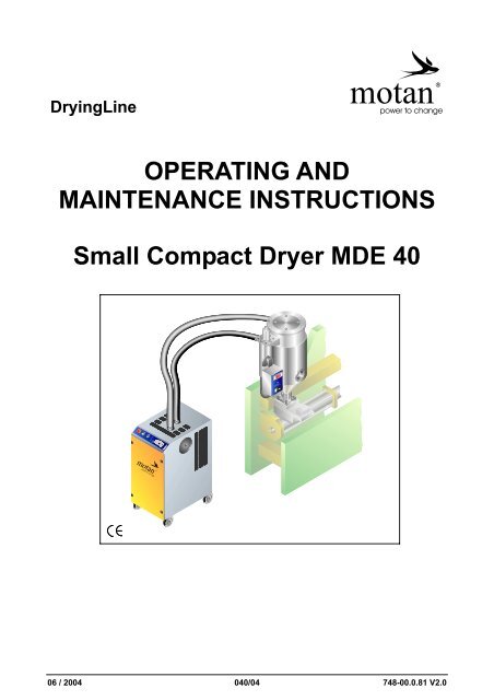
<strong>OPERATING</strong> <strong>AND</strong><br />
<strong>MAINTENANCE</strong> <strong>INSTRUCTIONS</strong><br />
<strong>Small</strong> <strong>Compact</strong> Dryer MDE 40<br />
06 / 2004 040/04 748-00.0.81 V2.0
Details relating to the unit MDE 40<br />
2 Details relating to the unit<br />
2.1 Use in accordance with specifications<br />
The small compact drier MDE 40 is used exclusively to dry hygroscopic plastics granulates.<br />
2.2 Technical data<br />
2.2.1 <strong>Small</strong> compact drier<br />
Dry air volume ........................................................................................................................................ 40 m 3 /h<br />
Heating capacity of regeneration air heater, per cartridge ..................................................................... 1,0 kW<br />
Inductive load (motor) .......................................................................................................................... 0,25 kVA<br />
Ohmic load ...................................................................................................................................... max. 1,0 kW<br />
Operating voltage ............................................................................................................ 1 / 230 V/N/PE/50 Hz<br />
Power consumption ......................................................................................................................... approx. 6 A<br />
Max. connected load .............................................................................................................................. 1,3 kW<br />
Weight .......................................................................................................................................... approx. 60 kg<br />
Noise level ........................................................................................................................................... < 70 dBA<br />
Dimensions ...................................................................................................................................... see Fig. 2-1<br />
2.2.2 Drying bins<br />
Temperature range ........................................................................................................................ 60 to 140 °C<br />
Heating capacity, per bin ........................................................................................................................ 1,5 kW<br />
Operating voltage ............................................................................................................ 1 / 230 V/N/PE/50 Hz<br />
Connected load with 230 V, per bin ................................................................................................ approx. 7 A<br />
Max. connected load ............................................................................................................................ 1,55 kW<br />
Volume ................................................................................................................................. 15, 30 and 60 liters<br />
Number of drying bins, volume 15 and 30 liters ................................................................................. max. 2 off<br />
Number of drying bins, volume 60 liters ...................................................................................................... 1 off<br />
Weight (net)15/30/60 liters ................................................................................................. approx. 12/15/20 kg<br />
Dimensions ...................................................................................................................................... see Fig. 2-1<br />
Performance range (in kg/h at a residual moisture content of 0,02 %)<br />
Examples<br />
Material MDE 40/15<br />
max. kg/h*<br />
MDE 40/30<br />
max. kg/h*<br />
MDE 40/30<br />
max. kg/h*<br />
ABS 4,5 9,0 18,0<br />
PA 6 1,5 3,0 9,0<br />
PA 6.6 1,5 3,0 9,0<br />
PC 4,5 9,0 18,0<br />
PEEK 4,0 8,0 16,0<br />
PBTP 3,0 6,0 12,0<br />
LCP 3,0 6,0 12,0<br />
PPS 4,0 8,0 16,0<br />
PSU 4,0 8,0 16,0<br />
*dependent of bulk density, residence time and initial humidity<br />
2.1
Details relating to the unit MDE 40<br />
<strong>Small</strong> compact<br />
drier<br />
Drying bins<br />
15 liters<br />
30 liters<br />
60 liters<br />
Connecting flange<br />
* Connection for hopper loader prepared<br />
** Option<br />
Fig. 2-1<br />
Dimensions: <strong>Small</strong> compact drier and drying bins<br />
2.2
Details relating to the unit MDE 40<br />
Fig. 2-6<br />
Dimensions with drying bin on the machine<br />
2.5
Assembly MDE 40<br />
3 Assembly<br />
Return air<br />
12<br />
4 th step<br />
13<br />
Process air<br />
1<br />
2<br />
12<br />
3<br />
3 rd step<br />
Black<br />
Grey<br />
7<br />
4<br />
2<br />
5<br />
6<br />
7<br />
8<br />
9<br />
10<br />
1 st step<br />
2<br />
11<br />
2 nd step<br />
Fig. 3.1<br />
Assembly – one drying bin<br />
Item No.off Designation<br />
Item No.off Designation<br />
1 4 Hexagon screw M8x45 DIN 933 8 2 Spring washer B10 DIN 127<br />
2 10 Washer 8,4 DIN 125 9 2 Cheese-head screw M10x20 DIN 912<br />
3 1 Shut-off slide (option) 10 2 Caster with brake dia. 75<br />
4 1 Suction box 11 2 Hexagon screw M8x80 DIN 933<br />
5 4 Spring washer DIN 127 12 4 Hose clamp dia. 38-50<br />
6 4 Hexagon nut DIN 934 13 2 Hose<br />
7 4 Square stopper<br />
3.1
Assembly MDE 40<br />
12<br />
14<br />
12<br />
Return air<br />
13<br />
Process air<br />
14 18 17<br />
12<br />
17<br />
12 14 18<br />
17<br />
16<br />
15<br />
17<br />
Return air<br />
17<br />
See<br />
Fig. 3-1<br />
13<br />
12<br />
14<br />
12<br />
17<br />
Process air<br />
12<br />
Grey<br />
See<br />
Fig. 3-1<br />
12<br />
Black<br />
2<br />
16<br />
6<br />
2<br />
Fig. 3-2<br />
Assembly – two drying bins<br />
Item No.off Designation Item No.off Designation<br />
1 8 Hexagon screw M8x45 DIN 933 11 2 Hexagon screw M8x80 DIN 933<br />
2 22 Washer 8,4 DIN 125 12 8 Hose clamp dia. 38-50<br />
3 2 Shut-off slide 13 4 Hose<br />
4 2 Suction box 14 2 T piece dia. 45<br />
5 8 Spring washer DIN 127 15 2 Pipe clip dia. 45<br />
6 10 Hexagon nut DIN 934 16 2 Hexagon screw M8x130<br />
7 8 Square stopper 17 6 Pipe clamp coupling dia. 45, assembled<br />
8 4 Spring washer B10 DIN 127 18 2 Blind plug<br />
9 4 Cheese-head screw<br />
19 2 Hexagon screw M8x130<br />
M10x20 DIN 912<br />
10 4 Caster with brake dia. 75<br />
Bolt support frames<br />
Bolt drying bin on the support frame as per Fig. 3-1<br />
Fit and attach hoses<br />
3.2
Assembly MDE 40<br />
Move the small compact drier to the<br />
designated location and fix casters<br />
Mount drying bin onto the injection moulding<br />
machine, if necessary<br />
Check location of the screen insert<br />
(1, Fig. 3-3) in the drying bin (2). To do this:<br />
- open lid of the drying bin<br />
- carry out visual check<br />
- if necessary, put screen insert in the<br />
correct position<br />
If necessary, mount hopper loader onto the<br />
drying bin<br />
Operating Instructions for hopper loaders<br />
1<br />
2<br />
Fig. 3-3<br />
Screen insert in the drying bin<br />
Remove blanking plugs on the sockets<br />
Connect small compact drier and drying bin with the drying hoses and the hose clips as per Fig. 3-4<br />
Return air<br />
Process air<br />
Pipe socket:<br />
black<br />
Pipe socket:<br />
grey<br />
Multiple socket<br />
(option)<br />
Fig. 3-4<br />
Attaching the drying hoses<br />
Connect compact drier and drying bin to the power supply (230 V) and plug in drying bin at the multiple<br />
socket<br />
3.3
Function MDE 40<br />
4 Function<br />
4.1 Function principle<br />
The blower (2, Fig. 4-1) pulls moist air from the drying bin air via a preconnected filter (3). This air is mixed<br />
with a small part of ambient air. Via the reversing valve (1) the air mix is blown into the desiccant cartridge 2<br />
(5). At this point, the moisture is extracted from this air by means of a desiccant (absorption medium).<br />
1<br />
2<br />
3<br />
4<br />
5<br />
7<br />
6<br />
Fig. 4-1<br />
Function layout<br />
The dried air from the desiccant cartridge flows into the heater on the drying bin, where it is heated to the<br />
preselected temperature. A separate heater is allocated to each drying bin. This makes it possible to set a<br />
different temperature for each drying bin.<br />
The hot air flows uniformly distributed from the bottom to the top through the plastic granulate, heating and<br />
drying it. The hot and moist air is then aspirated once again by the blower.<br />
When the desiccant in the desiccant cartridges is saturated, it will not absorb any more moisture, and must<br />
be regenerated. This regeneration process operates in parallel with the drying process in the desiccant<br />
cartridge 1.<br />
A part of the dried air from desiccant cartridge 2 flows through desiccant cartridge 1, where it is heated by<br />
the regeneration heater (7) and dries the saturated desiccant. Then, the air flows through the reversing valve<br />
into the open air.<br />
After a preset time the reversing valve switches over. The moist air arrives in desiccant cartridge 1 where it<br />
is dried. The regeneration heater (6) is activated and the desiccant in the desiccant cartridge 2 is<br />
regenerated.<br />
4.1
Operation MDE 40<br />
5 Operation<br />
5.1 Switch-on<br />
The prerequisites for trouble-free operation:<br />
<strong>Small</strong> compact dryer and drying bins are plugged in and connected with the air hoses<br />
Hopper loader on the drying bin is ready for operation or<br />
in case of manual filling: Dummy cover on the drying bin is closed<br />
When granulate with a health risk is dried, the regenerating<br />
air has to be carried off!<br />
Safety instructions of the manufacturer have to be<br />
observed!<br />
During operation with maximum<br />
temperature, some parts of the system<br />
might become hot.<br />
Don't touch the system! Risk of injury!<br />
5.1.1 Displays and settings at the drying bin control<br />
1<br />
2<br />
3<br />
4<br />
Fig. 5-1<br />
Dixell control<br />
Item Designation Function / Display / Operation<br />
1 LED Lights up: heater switched on<br />
2 LED Flashes: when drying temperature is displayed while button 4 is pressed<br />
3 Arrow For modifying the values<br />
Displaying the drying temperature press briefly<br />
4 SET<br />
Modifying the drying temperature press approx. 2 s<br />
Confirming the input<br />
press briefly<br />
5.1
Operation MDE 40<br />
5.1.2 Displaying/modifying the drying temperature<br />
Switch on the drying bin control at switch<br />
(4, Fig. 5-2)<br />
The display always shows the current actual<br />
temperature.<br />
1<br />
2<br />
Displaying the drying temperature:<br />
Briefly press "SET" (3)<br />
display is shown for 5 seconds<br />
3<br />
Modifying the drying temperature:<br />
Keep "SET" (3) pressed for approx. 2 seconds<br />
LEDs (1) flash<br />
Adjust the drying temperature with the arrow keys<br />
(2) or (e.g. 90 °C)<br />
Briefly press "SET"<br />
the value is accepted<br />
4<br />
The actual temperature is displayed again after 5<br />
seconds.<br />
Fig. 5-2<br />
Adjusting the drying temperature<br />
NOTE<br />
In case of faulty operation:<br />
Wait 5 seconds and the display will automatically show the actual<br />
temperature.<br />
5.2
Operation MDE 40<br />
5.1.3 Switching on the small compact dryer<br />
1<br />
2<br />
3<br />
Fig. 5-3<br />
Operating panel on the small compact dryer<br />
Item Designation Function / Display<br />
1 Main switch ON-OFF / EMERGENCY-OFF<br />
2 ON-OFF illuminated switch Switches small compact dryer on/off, lights up white when "ON"<br />
3 Alarm display Lights up red on malfunction<br />
Switch main switch to position "I" (1, Fig. 5-3) and<br />
put illuminated ON-OFF switch (2, Fig. 5-3) to position "I"<br />
illuminated switch lights up white<br />
the small compact dryer is switched on<br />
No further operating procedures are required. The entire granulate drying process operates automatically.<br />
When the heater at the drying bin is heating, the LED (1, Fig. 5-1) lights up.<br />
5.2 Switch-off<br />
Switch off the drying bin control with switch (4, Fig. 5-2)<br />
Put illuminated switch (2, Fig. 5-3) to "O" position<br />
White light (2, Fig. 5-3) goes out<br />
the small compact dryer and drying bins are switched off<br />
NOTE<br />
The blower runs on for approx. 20 seconds.<br />
For short operation interrupts (< 20 seconds) the drying bin control<br />
does not have to be switched off.<br />
5.3 Manual filling of the drying bin<br />
CAUTION<br />
While filling the drying bin with granulate take care that the cover of the<br />
drying bin will not close inadvertently.<br />
Risk of injury!<br />
5.3
Operation MDE 40<br />
5.4 Trouble-shooting<br />
Always disconnect the mains plug of the small compact<br />
dryer and the drying bin heater from the power supply<br />
before carrying out any fault rectifications.<br />
Secure EMERGENCY-OFF switch at the small compact dryer<br />
against unauthorised reconnection.<br />
Faults may only be rectified by authorised, trained and<br />
properly instructed specialists.<br />
At malfunction, the alarm display (3, Fig. 5-3) on the operating panel lights up.<br />
The faults listed are examples only, and are not to be regarded as exhaustive.<br />
Fault Cause Rectification<br />
lluminated "ON-OFF" <strong>Small</strong> compact dryer is not plugged in<br />
Plug in small compact dryer<br />
switch (2, Fig. 5-3)<br />
does not light up EMERGENCY-OFF switch not activated Activate EMERGENCY-OFF<br />
switch<br />
Illuminated switch (2, Fig. 5-3) is not switched on Switch on illuminated switch<br />
Power supply failure<br />
Check power supply<br />
Lamp defective<br />
Change lamp<br />
Fuse 12 F1 (9, Fig. 7-1) defective<br />
Change fuse 12 F1<br />
Blower is not Fuse 11 F3 (8, Fig. 7-1) defective Change fuse 11 F3<br />
operating Blower defective Change blower<br />
Alarm display Air pressure monitor (11, Fig. 7-2) defective Change<br />
(3, Fig. 5-3) lights up Blower is not operating Change fuse 11 F3<br />
Hose loose or leaking<br />
Check, change if necessary<br />
Air flow too weak<br />
Check hoses and connection<br />
for leaks<br />
Temperature limit switch for desiccant cartridge 1 Reset 6.3.1<br />
has switched off<br />
Temperature limit switch for desiccant cartridge 2 Reset 6.3.1<br />
has switched off<br />
Temperature limit switch defective<br />
Change<br />
Sensor or capillary tube of the temperature limit Change<br />
switch defective<br />
Wrong position of valve flap Adjust valve flap 6.3.6<br />
Temperature at<br />
drying bin does not<br />
reach set temperature<br />
Air flow too weak<br />
Differential pressure monitor (5, Fig. 7-3)<br />
defective<br />
Check hoses and<br />
connections for leaks<br />
Check 6.3.5<br />
change if necessary<br />
Safety thermostat has tripped Reset 6.3.4<br />
Heater defective<br />
Measure resistance,<br />
change if necessary<br />
5.4
Maintenance and repair MDE 40<br />
6 Maintenance and repair<br />
6.1 Maintenance intervals<br />
Prior to any repair work: Allow the drying system to cool<br />
down.<br />
All works concerning electrical installation and repair may<br />
only be carried out by appropriately trained electric<br />
engineers.<br />
Prior to electrical installation works:<br />
Disconnect the unit from the power supply and secure<br />
against inadvertent reconnection.<br />
Recommendation: Wear safety glasses and nose/mouth<br />
guard when carrying out dusty works.<br />
Weekly<br />
No. Test point / Designation Action Set value / Remarks<br />
1.1 Dry air filter Clean See section 6.2.1<br />
Clean more frequently in the<br />
event of high dust built-up<br />
1.2 Screen at air outlet Check for cleanliness,<br />
clean if necessary<br />
Clean more frequently in the<br />
event of high dust built-up<br />
1.1<br />
1.2<br />
Fig. 6-1<br />
Weekly maintenance works<br />
6.1
Maintenance and repair MDE 40<br />
Annually<br />
No. Test point / Designation Action Set value / Remarks<br />
2.1 Dry air filter Change See section 6.2.1<br />
2.2 Regeneration air heater Measure resistance Approx. 52 ,<br />
see section 6.2.2<br />
Triennially<br />
No. Test point / Designation Action Set value / Remarks<br />
3.1 Desiccant Change See section 6.2.3<br />
2.1<br />
3.1<br />
2.2<br />
Fig. 6-2<br />
Annual and triennial maintenance intervals<br />
6.2
Maintenance and repair MDE 40<br />
6.2 Servicing<br />
6.2.1 Cleaning the dry air filter<br />
Switch off dryer<br />
Lock main switch to secure against switch-on<br />
Unplug mains connection<br />
Disassemble dry air filter<br />
Recommendation:<br />
Wear safety glasses<br />
and nose/mouth guard.<br />
Blow dry air filter through with compressed air,<br />
from the inside to the outside<br />
see Fig. 6-3<br />
CAUTION<br />
The air filter housing must not be blown out<br />
with compressed air, since this could cause<br />
contamination of the desiccant.<br />
Disposal of the dry air filter as special refuse in<br />
accordance with the local offical regulations.<br />
Fig. 6-3<br />
Cleaning the dry air filter<br />
6.2.2 Checking the resistance of the regeneration air heaters<br />
Works at the electrical system may only be carried out by<br />
authorised and trained specialists.<br />
Power Voltage Resistance<br />
1,0 kW 230 V Approx. 52 <br />
Switch off small compact dryer<br />
Lock main switch to secure against switch-on<br />
Disconnect mains connection<br />
Check resistance of the regeneration air<br />
heaters on the terminal strip (Fig. 6-4):<br />
Measure resistance between:<br />
Terminal -X11=4 and terminal -X11=14<br />
Terminal -X11=6 and terminal -X11=16<br />
Fig. 6-4<br />
Check resistance<br />
6.3
Maintenance and repair MDE 40<br />
6.2.3 Changing the desiccant<br />
Remove clamping ring (1, Fig. 6-5) with<br />
silicone profile ring<br />
Remove cover<br />
Remove silicone (2)<br />
Remove screen plate (3)<br />
Remove desiccant (4) completely of the<br />
desiccant cartridge with a vacuum cleaner<br />
Remove silicone completely<br />
Reassambly:<br />
Fill in desiccant (3 kg per desiccant cartridge)<br />
Put screen plate in place<br />
Secure screen plate on three points at the<br />
edge with silicone<br />
Restore silicone profile ring<br />
Put cover in place and secure with the<br />
clamping ring<br />
1<br />
2<br />
3<br />
4<br />
Fig. 6-5<br />
Changing the desiccant<br />
6.3 Maintenance and repair<br />
6.3.1 Resetting the temperature limit switch<br />
Open door of the small compact dryer<br />
Resetting the temperature limit switch for<br />
desiccant cartridge 1:<br />
Press button at -12S5 (1, Fig. 6-6)<br />
Reset temperature limit switch for desiccant<br />
cartridge 2:<br />
Press button at 12S6 (2)<br />
1<br />
2<br />
Fig. 6-6<br />
Resetting the temperature<br />
limit switch<br />
6.4
Maintenance and repair MDE 40<br />
6.3.2 Changing the temperature sensor at the drying bin<br />
NOTE<br />
The temperature sensor (1, Fig. 6-7) must<br />
be fitted in a way that the slot lies in<br />
parallel to the air flow direction<br />
Fig. 6-7.<br />
1<br />
Air flow<br />
direction<br />
Fig. 6-7<br />
Fitting position of the<br />
temperature sensor<br />
6.3.3 Checking the air pressure monitor<br />
Remove hose (2, Fig. 6-8) at the pressure<br />
monitor (1)<br />
Air pressure monitor alright if<br />
<br />
<br />
alarm display lights up<br />
regeneration air heater switches off<br />
(in case the regeneration air heater is<br />
switched on)<br />
1<br />
2<br />
Fig. 6-8<br />
Checking the air pressure monitor<br />
6.5
Maintenance and repair MDE 40<br />
6.3.4 Resetting the safety thermostat<br />
Remove cap (1, Fig. 6-9)<br />
Press reset button<br />
6.3.5 Checking the differential pressure monitor<br />
The dryer is switched on.<br />
Remove both hoses (2, Fig. 6-9) at the differential pressure monitor (3)<br />
Blow gently into the hose;<br />
the differential pressure monitor is alright if:<br />
temperature is still rising<br />
LED "out" (1, Fig. 6-10) lights up<br />
1<br />
1<br />
2<br />
3<br />
Fig. 6-9<br />
Checking the differential pressure<br />
monitor<br />
Fig. 6-10<br />
Checking the differential<br />
pressure monitor<br />
6.3.6 Changing the valve<br />
Disconnect the small compact dryer from the<br />
power supply<br />
Mark the four hoses (1, Fig. 6-11) and remove<br />
them<br />
Remove the cover at the valve (3) and<br />
disconnect the cable<br />
Unscrew the two nuts (2) and remove the<br />
valve in forward direction<br />
3<br />
1<br />
1<br />
2<br />
1 2<br />
1<br />
1<br />
Assembly is carried out in reverse order.<br />
Fig. 6-11<br />
Changing the valve<br />
6.6
Spare parts MDE 40<br />
7 Spare parts<br />
Spare parts for electrical items see parts list at the circuit diagrams.<br />
1<br />
13<br />
12<br />
2<br />
3<br />
4<br />
11<br />
10<br />
5<br />
9<br />
6<br />
4<br />
7<br />
8 8<br />
Fig. 7-1 MDE 40<br />
Spare parts Fig. 7-1<br />
1 2 3 4 5<br />
Item No. off Designation / Type Part no. Remarks<br />
1 ar* Spiral hose dia. 45 mm 4072410 Black<br />
2 ar* Hose clip dia. 45 mm 1121860<br />
3 ar* Silicone hose dia. 45 mm 4070660 Red<br />
4 1 Profile clamp 4080580<br />
1 Silicone profile ring 4080570<br />
5 3 kg Molecular sieve (3 kg per desiccant cartridge) 1422200 Order also item 4<br />
6 1 Thermostat 4072500<br />
7 1 Heater 1,0 kW 4083130 Order also item 4<br />
8 4 Castor with lock 4072450<br />
9 1 Blower 5090060<br />
10 1 Differential pressure monitor 4065450<br />
11 1 Valve 5042420<br />
12 1 Dry air filter 4066330 Filter cartridge<br />
ar* Silicone seal 2x10 4060830<br />
13 1 Power supply, multiple socket 5013240 Option<br />
ar* = as required<br />
7.1
Spare parts MDE 40<br />
1<br />
2<br />
3<br />
4<br />
5<br />
6<br />
10<br />
7<br />
8<br />
9<br />
Fig. 7-2<br />
Drying bin<br />
Spare parts Fig. 7-2<br />
1 2 3 4<br />
Item No. off Designation / Type 15, 30 and 60 litres<br />
1 ar* Silicone seal 2x10 4060830<br />
2 1 Heating element 1,5 kW 4072430<br />
1 Heating element 2 kW 3056930<br />
3 1 Temperature limiter 4074480<br />
4 1 Seal 4072420<br />
5 1 Differential pressure monitor 4065450<br />
6 ar* Silicone hose 4067530<br />
7 ar* Silicone spiral hose dia. 45 4070660<br />
8 ar* Hose clip dia. 45 mm 1121860<br />
9 1 Temperature sensor 4072230<br />
10 1 Sight glass 4082800<br />
ar* = as required<br />
7.2
Option MDE 40<br />
A<br />
After cooler<br />
The after cooler is required for drying with very<br />
high temperatures (approx. > 120 °C).<br />
The cooler the return air temperature, the better<br />
the air absorption of the return air, i.e. efficiency<br />
of the drying system increases.<br />
The return air from the drying bins passes<br />
through the heat exchanger (1, Fig. A-1).<br />
1<br />
2<br />
The heat exchanger is cooled by the cooling air<br />
of the filter fan (2) during the entire time of<br />
operation.<br />
Fig. A-1<br />
After cooler<br />
Maintenance<br />
Clean the after cooler every three months.<br />
In case very dusty material is dried, clean the after cooler more often.<br />
Spare parts<br />
Spare parts<br />
Item No. off Designation Part no.<br />
- 1 After cooler, complete 501 459<br />
1 1 Heat exchanger 407 573<br />
2 1 Filter fan 403 652<br />
A.1