Bachelor Thesis A Qualitative Analysis of Two Automated ...
Bachelor Thesis A Qualitative Analysis of Two Automated ...
Bachelor Thesis A Qualitative Analysis of Two Automated ...

Create successful ePaper yourself
Turn your PDF publications into a flip-book with our unique Google optimized e-Paper software.
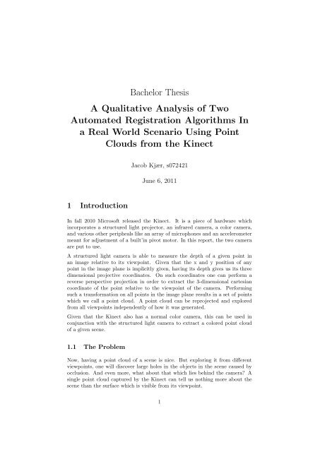
<strong>Bachelor</strong> <strong>Thesis</strong><br />
A <strong>Qualitative</strong> <strong>Analysis</strong> <strong>of</strong> <strong>Two</strong><br />
<strong>Automated</strong> Registration Algorithms In<br />
a Real World Scenario Using Point<br />
Clouds from the Kinect<br />
Jacob Kjær, s072421<br />
June 6, 2011<br />
1 Introduction<br />
In fall 2010 Micros<strong>of</strong>t released the Kinect. It is a piece <strong>of</strong> hardware which<br />
incorporates a structured light projector, an infrared camera, a color camera,<br />
and various other peripheals like an array <strong>of</strong> microphones and an accelerometer<br />
meant for adjustment <strong>of</strong> a built’in pivot motor. In this report, the two camera<br />
are put to use.<br />
A structured light camera is able to measure the depth <strong>of</strong> a given point in<br />
an image relative to its viewpoint. Given that the x and y position <strong>of</strong> any<br />
point in the image plane is implicitly given, having its depth gives us its three<br />
dimensional projective coordinates. On such coordinates one can perform a<br />
reverse perspective projection in order to extract the 3-dimensional cartesian<br />
coordinate <strong>of</strong> the point relative to the viewpoint <strong>of</strong> the camera. Performing<br />
such a transformation on all points in the image plane results in a set <strong>of</strong> points<br />
which we call a point cloud. A point cloud can be reprojected and explored<br />
from all viewpoints independently <strong>of</strong> how it was generated.<br />
Given that the Kinect also has a normal color camera, this can be used in<br />
conjunction with the structured light camera to extract a colored point cloud<br />
<strong>of</strong> a given scene.<br />
1.1 The Problem<br />
Now, having a point cloud <strong>of</strong> a scene is nice. But exploring it from different<br />
viewpoints, one will discover large holes in the objects in the scene caused by<br />
occlusion. And even more, what about that which lies behind the camera A<br />
single point cloud captured by the Kinect can tell us nothing more about the<br />
scene than the surface which is visible from its viewpoint.<br />
1
Point cloud registration is the act <strong>of</strong> matching such point-clouds captured from<br />
different viewpoints with each other so that they form a more completely representation<br />
<strong>of</strong> a given scene. It can be done by hand, but it is time-consuming<br />
and tedious. However, automated solutions have been proposed.<br />
The aim <strong>of</strong> this project is to analyze a real world scenario in which two implementations<br />
<strong>of</strong> such automatic registration algorithms are used to align point<br />
clouds captured by the Kinect. In what situations can the Kinect be used, and<br />
how well do the algorithms perform with regards to speed and precision<br />
2 Retrieving and Processing data from the Kinect<br />
While the Kinect was initially released as a gaming peripheal for the Xbox 360<br />
console, a set <strong>of</strong> targetted drivers were released around newyear 2011 as part<br />
<strong>of</strong> the OpenNI project along with a very useful library for interfacing with the<br />
device and a collection <strong>of</strong> high-level computervision functions.<br />
OpenNI provides everything needed for extracting a colored pointcloud from<br />
the Kinect. It can extract corresponding depth and color maps, calibrate them<br />
against each other, and perform the reverse perspective projection to cartesian<br />
coordinates as described in the introduction. Calibration <strong>of</strong> the color and depth<br />
map against each other is necessary because the source cameras for these maps<br />
are physically <strong>of</strong>fset from each other on a horizontal axis, and because the cameras<br />
have difference fields <strong>of</strong> view, and therefore different view frusta. The points<br />
on the depth map must be re-projected to the viewpoint <strong>of</strong> the color map for<br />
good correspondance. As written earlier, OpenNI can do that.<br />
OpenNI also abstracts all internal scales for depth and position to metric values.<br />
This is useful as it means that the device can exploited for measuring object<br />
sizes and lengths in a scene.<br />
3 <strong>Qualitative</strong> <strong>Analysis</strong> <strong>of</strong> the Input Data<br />
Through OpenNI the Kinect provides both color (24-bit RGB) and depth (formatting<br />
description follows) images in 640x480 resolution at a speed <strong>of</strong> 30Hz.<br />
This gives a theoretical upper limit <strong>of</strong> 640×480 = 307200 points in a pointcloud.<br />
In practice, a scene with optimal capturing conditions will result in a cloud <strong>of</strong><br />
around 265000 points. The color images are about as good as a decent webcam,<br />
and bayer noise is noticeable.<br />
3.1 Scanning surfaces with structured light<br />
TODO: De tre paragraffer her haenger ikke rigtigt sammen.<br />
The Kinect uses its infrared camera along its a structured light projector to<br />
estimate the surface <strong>of</strong> a scene as seen from the camera viewpoint. The projector<br />
projects an infrared pattern onto the scene which is captured by the infrared<br />
2
Figure 1: A Kinect-like setup with a single point-projector<br />
camera. The IR camera’s viewpoint is <strong>of</strong>fset on a horizontal axis relative to the<br />
projector.<br />
To illustrate how a structured light camera works, see figure 1 for a Kinectlike<br />
setup in which a projector is projecting just a single point (a very simple<br />
pattern) into space along the red line. It is captured by the camera once it hits<br />
a surface. There are three planes in the illustration; a reference plane, a plane<br />
closer to the camera than the reference plane, and a more distant plane. When<br />
the point hits a close plane it will appear further right in the image than if it<br />
was at the reference plane. Likewise, when the point is projected onto an object<br />
on a plane which is more distant than the reference plane, the point will appear<br />
more to the left.<br />
The Kinect has an image reference <strong>of</strong> what the pattern looks like from the cameras<br />
viewpoint when all point in the surface are at a certain, known distance.<br />
By comparing the horizontal position <strong>of</strong> a point in the captured image to its<br />
corresponding horizontal position in the reference image, a binocular disparity<br />
can be extracted, which in turn can be used to calculate the depth <strong>of</strong> the pixel.<br />
The Kinect itself actually does not calculate the depth, but returns a disparity<br />
for the host system to handle. While OpenNI abstracts this away for the<br />
developer, libfreenect makes these 11-bit values available.<br />
3.2 Precision Across the Depth Map<br />
According to Nicolas Burrus, who pioneered with information about the Kinect<br />
from his own experiments, the depth <strong>of</strong> a point z can be calculated in meters<br />
from the raw disparity <strong>of</strong> the point d (as provided by the Kinect hardware)<br />
using the following equation:<br />
z = 1.0/(d · −0.0030711016 + 3.3309495161)<br />
3
This equation is peculiar; d is an 11-bit integer which ranges from 0 to 2047. z<br />
will change sign from positive to negative when d is around 1084, so any practical<br />
use <strong>of</strong> values beyond that are useless for depth meassurement. I carried out tests<br />
with the Kinect pointing straight at a wall and found that it is was to unable<br />
to reliably meassure depth values below 50 cm (figure 2). These facts mean<br />
that only values <strong>of</strong> about 434 to 1084 are be actually useable to represent depth<br />
values. This is 650 unique disparity values, which is not a lot. Of these, all<br />
values up to 759 represent a depth <strong>of</strong> less than 1.0 m, meaning that half <strong>of</strong> all<br />
useful disparities output by the Kinect are in the range 50 cm to 1 m. And<br />
it falls exponentially; only 16 values in the range <strong>of</strong> disparities correspond to<br />
depths between 4 and 5 meters.<br />
The reason for this is likely that as objects come further away from the viewer,<br />
the effect <strong>of</strong> binocular disparity lessens, and thereby also the precision <strong>of</strong> the<br />
depth meassurement, so the engineers behind the hardware probably did not<br />
see much benefit in leaving any useful depth information in these ranges. So<br />
not only will objects which are far away from the viewer consist <strong>of</strong> less points<br />
because they take up a smaller area <strong>of</strong> the picture, but they will also be more<br />
coarse. The lesson here is that for any object more distant than 2.5-3.0 m,<br />
one cannot expect a faithful representation <strong>of</strong> its surface, and that any delicate<br />
details must be captured in a range <strong>of</strong> 60 cm to 1.5 m. Whether the hardware<br />
actually is precise at higher ranges is irrelevant because <strong>of</strong> the format in which<br />
it returns its meassurements is <strong>of</strong> too low fidelity.<br />
The gymball in figure 3 was shot at two distances, approximatly 2.5m and 80<br />
cm. The difference in precision is very noticeable - at a distance ball is hardly<br />
discernable, while at close point it is round and smooth.<br />
3.3 Artefacts from Structured Light<br />
Because the camera and projector are <strong>of</strong>fset by design, this means that not<br />
all points which are visible from the camera can always be illuminated by the<br />
projector. As a result holes may appear in the depth map where the projected<br />
pattern has been occluded (see figure 4)<br />
In general, infrared structed light will have many errors in environments consists<br />
<strong>of</strong> anything but diffuse surfaces, or environments with other sources <strong>of</strong> infrared<br />
light. For example the light <strong>of</strong> the sun, which created a hole in the test object<br />
(a gym ball) in figure 4 due to too much light being reflected back.<br />
3.4 Inconsistensies across multiple clouds<br />
TODO, fortael hvordan aendringer i lyssaetning og viewpoint kan have meget<br />
dramatisk effekt p hvordan scenen ser ud fra kameraet.<br />
Reference til figur 6.<br />
3.5 OpenNI/Kinect Stock Calibrations<br />
For the purpose <strong>of</strong> capturing point clouds, and computer vision in general,<br />
cameras are easiest to work with when they capture pictures in the way that an<br />
4
Figure 2: Emperical test <strong>of</strong> minimum supported depth <strong>of</strong> the hardware. Left:<br />
At over 50 cm, the wall is captured by the kinect (as shown on the screen).<br />
Right: At less than 50 cm, it is not. While these distances are approximat, one<br />
should operate with the Kinect well beyond them for the best results.<br />
Figure 3: Depth-map fidelity at far (left) and near (right) distances for the same<br />
round object. Pointclouds shown from the side.<br />
5
Figure 4: Example <strong>of</strong> projector-shadowing and local IR overexposure caused by<br />
sunlight.<br />
Figure 5: Edge <strong>of</strong> a pointcloud warping towards the viewer. This is supposed to<br />
be a straight wall. The green line was added post-capture to give an indication<br />
<strong>of</strong> where the edges <strong>of</strong> the wall should be.<br />
Figure 6: <strong>Two</strong> clouds taken from slightly different positions with a very short<br />
delay, and then registered onto each other. Notice how the brightness <strong>of</strong> the<br />
door and walls have changed noticeably just from a very minor adjustment.<br />
6
idealized pinhole camera would. Without going into too many formal details,<br />
it means that the center <strong>of</strong> the picture corresponds to what is directly straight<br />
in front <strong>of</strong> the camera, that all straight lines are perfectly straight, and that<br />
there are no other lense-caused distortions (such as fish-eye effects). Most 3d<br />
computer games use this camera model.<br />
The ROS team emperically meassured how much their Kinect cameras diverted<br />
from the pinhole camera model and found the difference to be very small.This<br />
is good.<br />
Inspection the point clouds provided by the Kinect through Kinect at OpenNI<br />
at close point, OpenNI’s calibration <strong>of</strong> the depth and color map is very decent<br />
out <strong>of</strong> the box. For distant objects, a near-perfect calibration is hard to acquire.<br />
Part <strong>of</strong> this can be attributed to the lowered precision <strong>of</strong> the depth meassurement<br />
at longer distances, and is therefore hard to do anything about clientside.<br />
At last, the corners <strong>of</strong> any point cloud will signs <strong>of</strong> a slight warping (see figure<br />
5). This cannot be solved with calibration, as even hand-calibrated clouds have<br />
this issue, so it is more likely due to a flaw in the IR projector or IR camera<br />
lens causing the edges to be distorted. As the IR data is used in the Kinect<br />
hardware, correcting these distortions properly would require a large effort.<br />
For the s<strong>of</strong>tware that goes with this project, it was decided that the quality <strong>of</strong><br />
the stock OpenNI calibration is not likely to be a major source <strong>of</strong> error, and<br />
that it therefore is good enough.<br />
4 The ICP Registration Algorithm<br />
The ICP algorithm is a very common registration algorithm devised in the<br />
early 90’s. It goes as following, where C m denotes a point cloud which is to be<br />
registered and moved to another point cloud with a static position, C s .<br />
1. For all points p m in C m , find the closest neighbooring point p s in P m .<br />
2. Find the rigid transformation, an orthogonal rotation R and a translation<br />
t, which minimizes the squared distances between the neighbooring pairs<br />
(enumerated with i):<br />
min<br />
R,t<br />
3. Apply the transformation to C m .<br />
∑<br />
||(Rp mi + t) − p si || 2<br />
4. Repeat until the algorithm has converged.<br />
i<br />
The translation part t <strong>of</strong> the rigid transformation is defined as the vector which<br />
will translate the center <strong>of</strong>f mass <strong>of</strong> the pair-matched points in C m to the center<br />
<strong>of</strong> mass <strong>of</strong> the corresponding points in C s :<br />
t = 1 n<br />
n∑<br />
(p mi − p si )<br />
i=1<br />
7
Where n denotes the amount <strong>of</strong> matched pairs found in step 1 <strong>of</strong> the algorithm,<br />
and i is used to enumerate these point pair entries so that (p mi , p si ) denotes<br />
the i’th pair. Notice that some points <strong>of</strong> C s may be the closest neighboor for<br />
several points in C m , meaning that they will be weighted more in the center <strong>of</strong><br />
mass calculations. This is intentional.<br />
Finding R is described in [GELbook]. The description <strong>of</strong> the procedure is an<br />
expanded paraphrase <strong>of</strong> their instructions:<br />
It can be shown that R can be found via singular value decomposition <strong>of</strong> the<br />
following matrix:<br />
H =<br />
n∑<br />
p mi p T si − 1 n<br />
n ( ∑ n∑<br />
p mi )( p si ) T<br />
i=1<br />
TODO: Skriv om multidimensionel ICP.<br />
i=1<br />
i=1<br />
5 The Features-based Registration Algorithm<br />
The feature-based registration algorithm is similar to ICP in that it searches<br />
for a set <strong>of</strong> matched pairs in the moving and the stationary pointcloud, and<br />
then finds the rigid tranformation which minimizes the sum <strong>of</strong> squared distance<br />
between these pairs. However, the algorithm is only run once, and the method<br />
<strong>of</strong> finding matching pairs <strong>of</strong> points in the two clouds is very different.<br />
It goes as following:<br />
1. Detect invariant features in the color-images from which C m and C s obtain<br />
their color information.<br />
2. Match the two sets <strong>of</strong> features detected in the source images to each other.<br />
3. Extract a set <strong>of</strong> matched pairs in 3D-space by corresponding the location<br />
<strong>of</strong> each feature with the point in the pointcloud which it maps to.<br />
4. Find the rigid transformation which minimizes the squared distance between<br />
the matched pairs. One can use the same procedure for this as<br />
described for ICP.<br />
Detection and matching <strong>of</strong> features are big problems in themselves, but the<br />
freely available library OpenCV <strong>of</strong>fers ready-made solutions which can be used<br />
for that.<br />
6 Implementation<br />
The two registration algorithms were implemented in C++ along with a user<br />
interface for the purpose <strong>of</strong> testing their performance.<br />
TODO: Skriv om hvordan ICP er implementeret (dimensioner, templates, KDTree<br />
fra GEL), hvordan Featurebased Registration er implementeret (OpenCV, Dynamic<br />
detectors), hvordan point clouds er lagret og behandlet, hvordan race<br />
conditions er blevet undget, hvordan UI’en fungerer<br />
8
7 Precision and performance<br />
8 Conclusion<br />
9 References<br />
9