cover - Encompass Imaging
cover - Encompass Imaging cover - Encompass Imaging
COVER 5. REPAIR PARTS LIST NOTE: • -XX, -X mean standardized parts, so they may have some differences from the original one. • Items marked “*” are not stocked since they are seldom required for routine service. Some delay should be anticipated when ordering these items. • The mechanical parts with no reference number in the exploded views are not supplied. • Due to standardization, replacements in the parts list may be different from the parts specified in the diagrams or the components used on the set. • CAPACITORS: uF: µF • COILS uH: µH • RESISTORS All resistors are in ohms. METAL: metal-film resistor METAL OXIDE: Metal Oxide-film resistor F: nonflammable • SEMICONDUCTORS In each case, u: µ, for example: uA...: µA... , uPA... , µPA... , uPB... , µPB... , uPC... , µPC... , uPD..., µPD... • Abbreviation CND : Canadian model AUS : Australian model EE : East European model NE : North European model JE : Tourist model CH : Chinese model KR : Korea model HK : Hong Kong model 5-1 When indicating parts by reference number, please include the board name. DCR-TRV33/TRV33E The components identified by mark 0 or dotted line with mark 0 are critical for safety. Replace only with part number specified. Les composants identifiés par une marque 0 sont critiques pour la sécurité. Ne les remplacer que par une pièce portant le numéro spécifié.
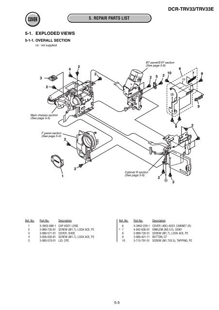
COVER 5-1. EXPLODED VIEWS 5-1-1. OVERALL SECTION ns : not supplied 3 2 Main chaises section (See page 5-5) F panel section (See page 5-4) 1 2 4 2 2 5. REPAIR PARTS LIST 2 5-3 Cabinet R section (See page 5-9) BT panel/EVF section (See page 5-8) Ref. No. Part No. Description Ref. No. Part No. Description 1 X-3953-088-1 CAP ASSY, LENS 2 3-989-735-81 SCREW (M1.7), LOCK ACE, P2 3 3-080-571-01 COVER, SHOE 4 3-056-030-81 SCREW (M1.7), LOCK ACE, P2 5 3-080-570-01 LID, CPC 2 5 2 2 A DCR-TRV33/TRV33E 10 6 X-3953-229-1 COVER (40E) ASSY, CABINET (R) * 7 4-942-636-01 EMBLEM (NO.3.5), SONY 8 3-989-735-51 SCREW (M1.7), LOCK ACE, P2 9 3-080-421-11 BUTTON, CF 10 3-713-791-51 SCREW (M1.7X3.5), TAPPING, P2 A 2 8 6 ns 7 2 9 8
- Page 23 and 24: 2-14. VA-118 BOARD, LENS SECTION 7
- Page 25 and 26: 2-17. MECHANISM DECK, VC-313 BOARD
- Page 27 and 28: F panel section 40 21 41 20 IC4101
- Page 29 and 30: 2-22.FLEXIBLE BOARDS LOCATION The f
- Page 31 and 32: DCR-TRV33/TRV33E OVERALL SECTION -2
- Page 33 and 34: COVER Link 3. BLOCK DIAGRAMS OVERAL
- Page 35 and 36: DCR-TRV33/TRV33E COVER 3-2. OVERALL
- Page 37 and 38: DCR-TRV33/TRV33E COVER 3-4. OVERALL
- Page 39 and 40: DCR-TRV33/TRV33E COVER 3-6. POWER B
- Page 41 and 42: DCR-TRV33/TRV33E COVER COVER 4-2. S
- Page 43 and 44: COVER Link CD-431 BOARD (CCD IMAGER
- Page 45 and 46: COVER 4-2. SCHEMATIC DIAGRAMS A B C
- Page 47 and 48: COVER For Schematic Diagram • Ref
- Page 49 and 50: COVER For Schematic Diagram • Ref
- Page 51 and 52: COVER For Schematic Diagram • Ref
- Page 53 and 54: COVER For Schematic Diagram • Ref
- Page 55 and 56: A B C D COVER 4-2. SCHEMATIC DIAGRA
- Page 57 and 58: COVER For Schematic Diagram • Ref
- Page 59 and 60: COVER Link 4-3. PRINTED WIRING BOAR
- Page 61 and 62: COVER 4-2. SCHEMATIC DIAGRAMS 4-3.
- Page 63 and 64: COVER 4-2. SCHEMATIC DIAGRAMS 4-3.
- Page 65 and 66: COVER 4-2. SCHEMATIC DIAGRAMS 4-3.
- Page 67 and 68: COVER 4-2. SCHEMATIC DIAGRAMS 4-3.
- Page 69 and 70: COVER 4-2. SCHEMATIC DIAGRAMS 4-3.
- Page 71 and 72: COVER 4-5. MOUNTED PARTS LOCATION C
- Page 73: COVER Link Link 5. REPAIR PARTS LIS
- Page 77 and 78: COVER 5-1-3. MAIN CHASSIS SECTION n
- Page 79 and 80: COVER 5-1-5. CABINET L SECTION ns :
- Page 81 and 82: Ver 1.1 2003. 06 COVER 5-1-7. CABIN
- Page 83 and 84: Ver 1.1 2003. 06 COVER 5-1-9. OVERA
- Page 85 and 86: COVER 5. REPAIR PARTS LIST 5-1-11.
- Page 87 and 88: Ref. No. Part No. Description Ref.
- Page 89 and 90: Ref. No. Part No. Description Ref.
- Page 91 and 92: Ref. No. Part No. Description Ref.
- Page 93 and 94: Ver 1.1 2003. 06 Checking supplied
- Page 95 and 96: SERVICE MANUAL Ver 1.2 2003. 09 DCR
COVER<br />
5-1. EXPLODED VIEWS<br />
5-1-1. OVERALL SECTION<br />
ns : not supplied<br />
3<br />
2<br />
Main chaises section<br />
(See page 5-5)<br />
F panel section<br />
(See page 5-4)<br />
1<br />
2<br />
4<br />
2<br />
2<br />
5. REPAIR PARTS LIST<br />
2<br />
5-3<br />
Cabinet R section<br />
(See page 5-9)<br />
BT panel/EVF section<br />
(See page 5-8)<br />
Ref. No. Part No. Description Ref. No. Part No. Description<br />
1 X-3953-088-1 CAP ASSY, LENS<br />
2 3-989-735-81 SCREW (M1.7), LOCK ACE, P2<br />
3 3-080-571-01 COVER, SHOE<br />
4 3-056-030-81 SCREW (M1.7), LOCK ACE, P2<br />
5 3-080-570-01 LID, CPC<br />
2<br />
5<br />
2<br />
2<br />
A<br />
DCR-TRV33/TRV33E<br />
10<br />
6 X-3953-229-1 COVER (40E) ASSY, CABINET (R)<br />
* 7 4-942-636-01 EMBLEM (NO.3.5), SONY<br />
8 3-989-735-51 SCREW (M1.7), LOCK ACE, P2<br />
9 3-080-421-11 BUTTON, CF<br />
10 3-713-791-51 SCREW (M1.7X3.5), TAPPING, P2<br />
A<br />
2<br />
8<br />
6<br />
ns<br />
7<br />
2<br />
9<br />
8


