Snow Melting Cables installation manual - Warmup
Snow Melting Cables installation manual - Warmup
Snow Melting Cables installation manual - Warmup

You also want an ePaper? Increase the reach of your titles
YUMPU automatically turns print PDFs into web optimized ePapers that Google loves.
The world’s best-selling electric floor heating brand<br />
Installation Manual:<br />
<strong>Snow</strong> <strong>Melting</strong> & De-Icing<br />
Mats and <strong>Cables</strong><br />
for use under Asphalt, Concrete or Pavers<br />
IMPORTANT<br />
Read this <strong>manual</strong> before attempting to install your heating<br />
system. Incorrect <strong>installation</strong> could damage the heating system<br />
and will invalidate your warranty.<br />
TECHNICAL HELPLINES<br />
US:1-888-927-6333<br />
Canada:1-888-592-7687
Table of Contents<br />
Product Specification.................................................2<br />
Construction of <strong>Snow</strong> Melt Systems............................2<br />
Sizing Guides.............................................................2<br />
Before Installation.....................................................3<br />
Control of <strong>Snow</strong> Melt System.....................................4<br />
Electrical Provisioning............................................5-6<br />
Installation - under Asphalt......................................7<br />
Installation - under Concrete...................................8-9<br />
Installation - under Pavers........................................10<br />
How to Modify the Mat..........................................11<br />
Installation of loose cables.......................................12<br />
Connection Diagram................................................13<br />
Draw Your Plan.......................................................14<br />
Warranty & Exclusions............................................15<br />
PRODUCT SPECIFICATION AND<br />
DETAILS<br />
Type<br />
Voltage<br />
Twin Conductor<br />
120V, 208V, 240V<br />
<strong>Snow</strong> <strong>Melting</strong> Mats/<strong>Cables</strong> are uniquely designed<br />
for snow melting in parking lots, driveways,<br />
pavements, stairs, bridges, roofs, etc. with total<br />
safety. <strong>Snow</strong> melting systems are heating cables<br />
taped to a sturdy mesh for fast, easy <strong>installation</strong>.<br />
<strong>Snow</strong> <strong>Melting</strong> Mats and <strong>Cables</strong> consist of a<br />
twin conductor heating cable taped onto the<br />
Polypropylene mat. The heating cable is laid in a<br />
winding fashion so that they are equally spaced<br />
(3” apart) and evenly distributed on the mat.<br />
Output 50W/sq ft (540W/sq m)<br />
Element Sizes<br />
6 to 120 sq ft<br />
Lead 16’ 4”<br />
Bending Radius Minimum 1-1/2”<br />
Cable Diameter 1/4”<br />
Wire Insulation<br />
Fluoropolymer<br />
Casing<br />
Zero Halogen Polyolefin<br />
Max Temperature 464°F / 240°C<br />
Min Installation Temp<br />
14°F / -10°C<br />
CONSTRUCTION AND SELECTION OF SNOW MELTING MAT AND CABLE<br />
The Heating Cable on the <strong>Snow</strong> <strong>Melting</strong> systems consists of a resistance-heating element insulated with<br />
Fluoropolymer and Polyolefin-based compound, having high dielectric strength and good temperature<br />
stability, which makes the heating cable totally safe. A metallic sheath is provided to give additional<br />
mechanical strength and provide ground path. A final outer jacket of Zero Halogen Polyolefin based<br />
compound is given to make it sturdier and provide corrosion protection. The heating cable consists of a<br />
cold lead as required. The hot and cold junction is uniquely designed to make it safe and easy.<br />
<strong>Warmup</strong> <strong>Snow</strong> <strong>Melting</strong> Sizing Guide<br />
Area (ft²) Mats Size (W X L) Resistance (Ω) Wattage (W) Amps (A)<br />
120 VOLT<br />
240 VOLT<br />
6.0 WSMM-D-0300-120 2’ x 3’ 48.0 300 2.5<br />
10.0 WSMM-D-0500-120 2’ x 5’ 28.8 500 4.2<br />
20.0 WSMM-D-1000-120 2’ x 10’ 14.4 1000 8.3<br />
30.0 WSMM-D-1500-120 2’ x 15’ 9.6 1500 12.5<br />
40.0 WSMM-D-2000-120 2’ x 20’ 7.2 2000 16.7<br />
50.0 WSMM-D-2500-120 2’ x 25’ 5.8 2500 29.8<br />
60.0 WSMM-D-3000-120 2’ x 30’ 4.8 3000 25.0<br />
6.0 WSMM-D-0300-240 2’ x 3’ 192.0 300 1.3<br />
10.0 WSMM-D-0500-240 2’ x 5’ 115.2 500 2.1<br />
20.0 WSMM-D-1000-240 2’ x 10’ 57.6 1000 4.2<br />
30.0 WSMM-D-1500-240 2’ x 15’ 38.4 1500 6.3<br />
40.0 WSMM-D-2000-240 2’ x 20’ 28.8 2000 8.3<br />
50.0 WSMM-D-2500-240 2’ x 25’ 23.0 2500 10.4<br />
100.0 WSMM-D-5000-240 2’ x 50’ 11.5 5000 20.8<br />
120.0 WSMM-D-6000-240 2’ x 60’ 9.6 6000 25.0<br />
240 VOLT<br />
<strong>Cables</strong><br />
Length<br />
(ft)<br />
Resistance<br />
(Ω)<br />
Wattage<br />
(W)<br />
2<br />
Amps<br />
(A)<br />
Coverage<br />
at 3”<br />
spacing<br />
(sqft)<br />
Coverage<br />
at 4”<br />
spacing<br />
(sqft)<br />
Coverage<br />
at 5”<br />
spacing<br />
(sqft)<br />
WSM-D-240V-40W/1000 84 57.1 1000 4.2 20 27 34<br />
WSM-D-240V-40W/2000 168 28.9 2000 8.3 43 57 72<br />
WSM-D-240V-40W/2500 209 23.1 2500 10.4 51 67 84<br />
WSM-D-240V-40W/3000 251 19.2 3000 12.5 62 84 104<br />
WSM-D-240V-40W/4500 375 12.8 4500 18.8 90 123 150<br />
WSM-D-240V-40W/5000 420 11.5 5000 20.8 100 140 170<br />
WSM-D-240V-40W/5500 458 10.5 5500 22.9 110 155 190
IMPORTANT INSTRUCTIONS BEFORE INSTALLATION OF THE SYSTEM<br />
Measure and plan the area to be heated with the snow melt mats/cables, allowing for obstructions such<br />
as lights, poles, columns, handrails or drains. For complete snow removal, select mats to cover the entire<br />
area.<br />
1. The heating cable should not cross or overlap itself at any point. This could cause the cable to<br />
overheat, requiring replacement.<br />
2. The heating cable should not be cut, shortened or lengthened.<br />
3. The heating cable length should NOT be altered under any circumstances. This may cause<br />
overheating, resulting in damage to the cable.<br />
4. Take precautions to avoid damage to the heating cable during <strong>installation</strong>. Do NOT drop sharp<br />
objects or drive on the cable. Take care when pouring concrete or asphalt onto the cable.<br />
5. Installation of the snow melt mats and cables should not be undertaken if ambient temperature is<br />
below 14°F (-10°C).<br />
6. Minimum bending radius of the heating cable while laying shall not be less than approximately 2<br />
inches (50mm) or not less than 10 times its diameter.<br />
7. The cold lead, normally 16’4” long (5m), can be cut/extended to suit the location of the electrical<br />
power connection box.<br />
8. <strong>Snow</strong>/Moisture detection sensor location shall be in the open area, away from trees or bushes,<br />
so that it can sense moisture in the air/snowfall and initiate the energization of the heating cable.<br />
9. Check the voltage and wattage of the heating cable to ensure you have the right products for<br />
your <strong>installation</strong>. Details are marked on the product box.A qualified electrician should connect the<br />
heating system.<br />
10. Check the continuity and resistance of the snow melting mat before installing and also after<br />
installing. Resistance value should match the value shown in the Sizing Guide on the previous page.<br />
A tolerance of 5% to 10% is allowed.<br />
11. Keep high voltage power wires in a separate conduit from the low voltage wire.<br />
12. <strong>Snow</strong> <strong>Melting</strong> Mats/Cable should be connected to a GFEP protected breaker in the panel. Consult<br />
a qualified electrician.<br />
13. Allow sufficient drying or curing period of the concrete/asphalt/sand after installing the snow<br />
melting mat / cable and before energizing the heating cable.<br />
14. For easy reference, attach a label at the power distribution board indicating the location of the<br />
snow melting mats / cables installed.<br />
15. All outdoor embedded <strong>installation</strong>s must include the application of a nameplate provided by the<br />
manufacturer under NEC 426-13.<br />
NOTE: The <strong>installation</strong> shall be in accordance with all enclosed instructions and in compliance with local<br />
and national electrical codes, namely part 426 of ANSI/NFPA, the NEC and CEC (Canadian Electrical<br />
Code), part 1 (re: GFCI, GFEP and RDC’s).<br />
WARNING!<br />
The cable must NOT be shortened or cut in any manner or subjected to strain at the cable/splice point.<br />
NEVER power up the heating cable prior to being buried in concrete, asphalt or in sand (even for testing<br />
purposes). This will prevent premature failure of the heating cable.<br />
Connecting the cable to the mains should be undertaken only by an authorized electrician.<br />
3
CONTROL OF SNOW MELTING SYSTEM<br />
Your <strong>Warmup</strong> <strong>Snow</strong> <strong>Melting</strong> system should ideally be<br />
controlled by the approved and supported <strong>Warmup</strong><br />
control devices. They can take the form of intelligent<br />
dual zone control panels, mounted indoors (ETO2<br />
Panels), or simpler outdoor boxes with integrated<br />
sensors (DS-Series: DS2-DS5-DS8).<br />
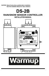
<strong>Snow</strong> Sensor and Controller<br />
When using the DS-series, there are no ground or roof<br />
sensors to prepare for (except gutter sensor for DS8).<br />
When choosing the more integrated control panel<br />
(ETO2), carefully read the following sections when<br />
preparing for your sensor positioning.<br />
RELAY CONTACTORS<br />
Note the difference between a control panel and a<br />
relay contactor. A control panel effectively reads the<br />
information from the sensors and sends the required<br />
signals to the heating cable. Depending on the models<br />
available, they can be programmable and user-defined.<br />
However, when using a large amount of heating cables (usually over 45Amps), <strong>Warmup</strong> will recommend<br />
the use of one or multiple contactor panels. The contactor panels will receive the connections from the<br />
heating cable leads, and subsequently be connected to the actual control devices. Call your <strong>Warmup</strong><br />
representative with any questions.<br />
INSTALLING SENSORS - CONDUITS AND FEEDER CABLE<br />
When using the ETO2 controller and other indoor mounted options available from <strong>Warmup</strong>, you will<br />
have to install one or more ground and/or roof sensors. Ground and roof sensors can be combined on<br />
the same controller. The reason for installing multiple sensors is to gather faster or more diversified<br />
information to trigger your heating system, such as the north and south side of a building.<br />
PLACEMENT OF SENSORS<br />
One basic principle is to locate one sensor where the snow and ice will manifest first, and another where<br />
the snow is going to disappear last. This will guarantee complete clearing of snow and ice. For example,<br />
on a sloped down driveway to an underground garage, place a sensor at the top and at the bottom of the<br />
driveway. Remember a combination of sensors can be ground-ground or ground-roof.<br />
When using only one sensor, you will have to choose between fast detection or the lasting melting<br />
period (place it where the snow will disappear last).<br />
Ground sensors must be placed within the heated area. Ground sensors for the ETO2 panels detect<br />
moisture and temperature and should therefore be located halfway between the wires, anywhere within<br />
the heating area, and preferably 3 ft within the edges of the heated zone. Always maintain a minimum<br />
distance of 1” between the sensor conduits, sensors and the actual heating cable. Finally, never place<br />
two sensors within 3ft of each other.<br />
4
CONDUITS<br />
After choosing the location of the sensors, you must install PVC or METAL conduits and ensure the<br />
connections are properly sealed. The mounting base for the ground sensor provides for it to be secured<br />
to a base (wood block, concrete block) in order to not push it down during or after the concrete pour.<br />
Always ensure the conduits are secured to the base (rebar, drained gravel base, blocks) so that they do<br />
not move during the pour.<br />
The conduits must route from the sensor location to the control panel. Check the specifications of the<br />
ground sensor you selected, and the length of its tail. You may need to install a feeder cable to extend<br />
the sensor to the panel.<br />
NOTE: INSTALLATION IN ASPHALT<br />
The temperature must not exceed 80 °C or 176 °F around the sensor and tube. Those temperatures are<br />
well below the typical asphalt pour temperatures, and we highly recommend the use of our reinforced<br />
cables specifically designed for asphalt. Always use METAL conduits for asphalt <strong>installation</strong>s, and install<br />
your sensor retroactively. Create a wooden perimeter to protect your sensor location from the pour, and<br />
subsequently affix the sensor in the ground, finishing the pour around that section.<br />
ELECTRICAL PROVISIONS<br />
The heating system <strong>installation</strong> wiring shall be in accordance with the national Electric Code and any<br />
applicable local codes. Controls and accessories recommended for use along with the heating cables<br />
are listed below:<br />
- Floor/Ground sensing temperature controller / thermostat<br />
- Plastic or wire zip ties<br />
- GFCI (Ground Fault Circuit Interrupter)<br />
- Dedicated circuit breaker(s) for all heaters circuits<br />
The location of the thermostat junction box shall be about 4’ (1.2m) high from the ground for easy<br />
access. The sensor wire and the heating cable cold leads shall be routed to the thermostat/power<br />
connection box in separate conduits.<br />
If the heating system has a load below 7,200W at 120V or 14,400W at 240V based on the thermostat<br />
power rating, it may be connected directly to an electronic thermostat as shown in the diagram below,<br />
and displays a typical scheme of the electrical system. If the heating system has a load of more than<br />
the thermostat power rating, contact <strong>Warmup</strong> on 1-888-927-6333.<br />
Heating Cable<br />
Controller<br />
HEATING SYSTEM Sensor<br />
All electrical connections should be performed by a licensed electrician and be in compliance<br />
with the appropriate local and national codes.<br />
Based on the amount of mats or cables purchased from <strong>Warmup</strong>, provide enough amperage<br />
supply to either control panel or the relay contactor. Check with your <strong>Warmup</strong> representative<br />
whether a contactor panel is used in your <strong>installation</strong>. Both are usually located next to each<br />
other, and mounted indoors.<br />
<strong>Warmup</strong>’s 24/7 Toll Free Technical Number: 1-888-927-6333<br />
5
ELECTRICAL PROVISIONS (cont’d)<br />
All circuits provided should be GFCI protected, however, some panels have a built-in GFEP protection.<br />
Check with your <strong>Warmup</strong> representative or refer to the specification sheet of the controllers purchased.<br />
Make sure to supply the appropriate power to the controller or relay panels in order to operate the<br />
mats and cables. The voltages available are 120V, 208V and 240V. Make sure you understand the proper<br />
wiring if a 208V-3 phase connection is necessary or recommended by your general contractor as your<br />
amperage load requirements will change.<br />
Note that the sensor wires can often be low voltage wires and should therefore ALWAYS be placed in<br />
their own, separate conduits. By the same token, while you may place multiple heating cable LEADS<br />
inside a single conduit, you should NEVER run the heating portion of the cable inside a PVC or METAL<br />
conduit.<br />
All lead wires may be lengthened or shortened as necessary, but NEVER cut the HEATING CABLE. When<br />
extending the lead wires, we recommend the use of a wall-mounted or in-ground weather-proof junction<br />
box.<br />
CABLE SPACING and HEATING OUTPUT<br />
When using the pre-assembled <strong>Warmup</strong> <strong>Snow</strong> <strong>Melting</strong> mats, the standard cable spacing is approximately<br />
3” and provides 50 watts of output per square foot.<br />
When using a loose cable format, or when spacing the mats <strong>manual</strong>ly, note that the maximum<br />
recommended spacing for snow melting is 4”, with an output of 37 watts per square foot. We do not<br />
recommend more than 5” and less than 2” for outdoor applications.<br />
CABLE DE-RATING<br />
It is possible and allowed to “de-rate” the power of a cable. In order to maintain the mats spaced as<br />
provided (3” spacing with 50w/sqft output), you can supply the 240V-rated mats with 208V power.<br />
ALWAYS CHECK WITH YOUR ELECTRICIAN and WARMUP REPRESENTATIVE for exact calculations.<br />
De-rating the mats from 240V to 208V will bring a 50w output down to 37w/sqft. This technique is used<br />
to obtain more coverage with less amperage load.<br />
MANUAL EXPANSION JOINTS (CONCRETE INSTALLATIONS)<br />
When installing mats and cables in concrete slabs, carefully prepare for the potential incisions for<br />
expansion joints in the concrete.<br />
Make sure the cable is not subjected to excess tension or strain. It should not cross an expansion joint.<br />
Where expansion joints are present, separate mats/cables should be used if possible.<br />
As an alternative, mark the location of the expansion joints on the sub-base with chalk or spray-paint<br />
and use the following technique: Apply a 2” x 2” downward bend or loop in the cable. This will cause<br />
for that section of cable to be deeper, thereby avoiding the blades, as well as provide for some level of<br />
flexibility when the slab expands and contracts during the various seasons.<br />
6
INSTALLATION INSTRUCTIONS - UNDER ASPHALT<br />
We highly recommend the use of our reinforced cable specifically designed for asphalt use. When using<br />
the regular snow melt mats/cables under asphalt, consider embedding them in sand or concrete first.<br />
Note: Using a megohmmeter and multi-meter, an electrician should measure the cable resistance and<br />
insulation resistance: (1) before commencing <strong>installation</strong>, (2) before applying asphalt and (3) after the<br />
asphalt is applied. Record the readings in this <strong>manual</strong>. If there is damage STOP and ring 1-888-927-6333.<br />
1. Ensure the contractor has a firm base of 4”-8” (102-203mm) of concrete, sand or rock aggregate<br />
tamped down and ready to receive the asphalt.<br />
2. Clean the area below the heating mat/cable so that it is free from sharp objects. It is extremely<br />
important to keep heavy equipment, machinery, vehicles, shovels and rakes away from the cable<br />
to prevent damage. In the application of asphalt, we recommend a maximum load of 2 tons for the<br />
roller. To minimize strain on the cable, lay the mats perpendicular to the roller’s path.<br />
3. Lay down the binder/base coat of asphalt and roller it smooth. The paving installer must decide if<br />
the binder coat of asphalt is allowed to cool before proceeding.<br />
4. Unroll the mat or place the cable on the prepared surface (wires facing down, mesh-side facing up<br />
to help protect the wire) according to your layout plan and apply a coat of bituminous binder. See<br />
pg 10 “How to Modify the Mat” if you need to alter the mats (Note: test the mats/cables to ensure<br />
they have not been damaged and record the readings).<br />
5. Once the mats/cables are in place, route the cold lead(s) provided through a rigid metal conduit to<br />
return to an accessible weatherproof junction box(es). The electrician may supply junction boxes<br />
which can be accessed from above so the rest of the box is buried to avoid damage by vehicles or<br />
lawn movers. [Note: ensure none of the heated section of the cable enters the conduit(s)]. Seal<br />
the ends of the conduit.<br />
6. Sensors can be placed within the asphalted area. Refer to earlier sections under PLACING GROUND<br />
SENSORS on page 3.<br />
7. When the mat/cable is embedded in sand or mortar, the asphalt should not exceed a thickness of<br />
more than 1.5” for optimal results. When pouring asphalt DIRECTLY on the mat/cable, let it cool to<br />
230F and below. Again, use a maximum of 2” of asphalt for optimal results.<br />
8. After the asphalt hardens, test and record results to verify that there is no damage and to ensure<br />
it is ready for activation once the asphalt has cured.<br />
9. For easy reference, attach a label at the power distribution board, indicating the location of the<br />
heating cables.<br />
Asphalt top coat<br />
<strong>Warmup</strong>® <strong>Snow</strong> Melt Mat<br />
Asphalt base<br />
4-8” of hardcore base<br />
7
INSTALLATION INSTRUCTIONS UNDER CONCRETE<br />
Note: Using a multi-meter, an electrician should measure the cable resistance and insulation resistance:<br />
(1) before commencing <strong>installation</strong>, (2) before pouring concrete and (3) after the concrete is poured.<br />
Record the readings. If there is damage STOP and ring 1-888-927-6333.<br />
1. Ensure the paving contractor has a solid base of 4”-8” (102-203mm) of crushed rock aggregate<br />
tamped down and ready to receive the pour.<br />
2. Clean the area below the heating mat/cable so that it is free from sharp objects. It is extremely<br />
important to keep heavy equipment, machinery, vehicles, sharp shovel and rake edges away from<br />
the cable to prevent damage.<br />
3. For locations that require handrails, it is strongly recommended that the concrete installer presleeves<br />
the posts to avoid any and all drilling of the concrete. The mat/cable must be routed around<br />
these sleeves/posts to avoid any direct contact with them. See pg 10 “How To Modify the Mat”<br />
if you need to alter the mats. The mat/cable must NOT pass through expansion joint locations.<br />
Avoid saw-cutting or drilling through cables that are no longer visible beneath the concrete by<br />
spray painting lines to mark exactly where expansion joints are located.<br />
4. Place the mat or cable down on top of the tamped aggregate with the mesh facing up. Stake the<br />
mesh or cable firmly into the crushed rock so that it remains flat. (Note: test the mats/cables to<br />
ensure they have not been damaged and record the readings.)<br />
5. Route the cold lead(s) through rigid PVC or metal conduit(s) to an accessible weatherproof junction<br />
box(es). Ensure that none of the heated section enters any conduit. Do not use excess force to pull<br />
the cold leads otherwise it may damage the hot-cold splice. Seal the conduit ends.<br />
6. A ground sensor can be placed outside the paved area. When placed within the paved area<br />
(recommended), ensure proper measuring and securing for the base of the sensor itself as it<br />
shouldn’t be flushed with the final coat of concrete. The sensor can be mounted on a wood or<br />
concrete block.<br />
7. A separate conduit should be used to protect the low voltage sensor wire and must NOT be shared<br />
with any high voltage cold lead from the mats/cables.<br />
8. Once the conduits & sensor(s) are in place, the sand can be poured, covering the mats/cables<br />
completely without leaving any air pockets, so that the cables are covered by 1.5” (38mm) of sand<br />
but not more than 2“” (51mm).<br />
9. An electrician MUST complete the final test and record results of all the mats/cables readings with<br />
a multi-meter and megohmmeter and verify that each mat/cable is in good working order and is<br />
ready for energizing once the sand has cured.<br />
10. For easy reference, tape your plan [pg 13] to a power distribution board, indicating the location of<br />
the heating cables.<br />
Concrete top coat<br />
<strong>Warmup</strong>® <strong>Snow</strong> Melt Mat<br />
Concrete base<br />
4-8” of hardcore base<br />
8
INSTALLATION INSTRUCTIONS UNDER CONCRETE (continued)<br />
FOR SINGLE POUR INSTALLATION<br />
1. Using a wire mesh or rebar, attach the snow melt mats/cables with plastic zip ties using 3”-4”<br />
(51mm-76mm).<br />
2. Then prop up the rebar/mesh with either concrete rubble or brick pavers to the appropriate depth<br />
so that the heating mat/cable ends up 2”-3” (51mm-76mm) from the finished surface and no deeper.<br />
Make sure the mesh-side is facing up, to protect the cable from shovels and rakes.<br />
3. Once the rebar/mesh/snow melting mat/cable is propped up, route the cold lead(s) through rigid<br />
metal or PVC conduit(s) to an accessible weatherproof junction box(es). Ensure that none of the<br />
heated section enters any conduit. Do not use excess force to pull the cold leads otherwise it may<br />
damage the hot-cold splice. Seal the conduit ends.<br />
4. A separate conduit should be used to protect the low voltage sensor wire and must NOT be shared<br />
with any high voltage cold lead from the mat cables.<br />
5. Once the conduits & sensor(s) are in place, the cement can be poured, covering the mats/cables<br />
completely without leaving any air pockets. The concrete should have a minimum thickness of 2“<br />
(50mm) measured from the top of the snow melting mat/cable.<br />
6. An electrician MUST complete the final test and record results of all the mat/cable readings with a<br />
multi-meter and megohmmeter and verify that each mat is in good working order and is ready for<br />
energizing once the sand has cured.<br />
7. For easy reference, tape your plan [pg 13] to a power distribution board, indicating the location of<br />
the heating cables.<br />
9
INSTALLATION INSTRUCTIONS UNDER PAVERS<br />
Note: Using a megohmmeter and multi-meter, an electrician should measure the cable resistance and<br />
insulation resistance: (1) before pouring sand and (2) after the sand is poured. Record the readings. If<br />
there is damage STOP and call 1-888-927-6333.<br />
1. Ensure the paving contractor has a solid base of 4”-8” (102-203mm) of crushed rock aggregate<br />
tamped down and ready to receive the mortar pour or sand/gravel base.<br />
2. Take extreme care to ensure the paver installer does NOT use any heavy equipment, machinery or<br />
vehicles over the exposed heating cables. We highly recommend the cable resistance be checked<br />
with a multimeter during the paving process by a qualified electrician. This will ensure detection of<br />
any unlikely faults as early as possible.<br />
3. For <strong>installation</strong> on stairs and ramps that will include hand rails, it is strongly recommended that<br />
the paver installer pre-sleeves the posts to avoid any and all drilling of the mortar. The heating<br />
mat/cable must be routed around these sleeves or posts to avoid any direct contact with them.<br />
When preparing for railings, expansion joints and related, please ensure the contractor has clearly<br />
marked and informed the paving/concrete contractor of the cable location.<br />
4. When laying the cables directly over a sand or gravel base, use landscape staples or provided cable<br />
strips to secure the mats and cables. Apply a second layer of gravel or sand of approximately 1”<br />
over the cables to ensure easy positioning of the pavers.<br />
5. Route the cold lead(s) through metal or PVC conduit(s) to an accessible weatherproof junction<br />
box(es). The electrician must ensure that none of the heated section enters any conduit. For this<br />
type of application, we recommend the use of the DS series aerial sensors to avoid cuts in pavers<br />
and stone. When using in-ground sensors with the ET02 controller, please make sure to plan ahead<br />
for correct placement of sensors within the stone. (Note: test the mats/cables to ensure they have<br />
not been damaged and record the readings.)<br />
6. Do NOT walk on the hot-cold factory splice and avoid damaging the mats/cables with shovels or<br />
rakes.<br />
7. The electrician needs to complete the final testing of all the snow melting mats/cables with a<br />
multi-meter to verify and record that each heating cable is still operational after the pour of mortar<br />
and cured. Record these values at the back of this <strong>manual</strong>.<br />
Pavers<br />
Sand<br />
<strong>Warmup</strong>® <strong>Snow</strong> Mat<br />
Sand<br />
4-8” of hardcore base<br />
10
HOW TO MODIFY THE SNOW MELT MAT<br />
Mats can be cut, turned and flipped to fit a specific area. NEVER CUT THE CABLE.<br />
<br />
90˚ Turn - cut & flip mat<br />
180˚ Turn - cut, and turn mat<br />
Basic Cut and Turn<br />
<br />
For other shapes, detach cable from mat to required length.<br />
Secure loose wire (attachment may vary).<br />
TESTING THE SNOW MELT MAT/CABLE<br />
A. Insulation Resistance (megohmmeter required)<br />
1. Connect one meter clamp to the cold lead inner conductor and the other meter clamp to the metal<br />
cable braided sheath (ground) of the heating cable.<br />
2. Test in accordance with the meter manufacturer’s instructions (recommended meter is a 500 VDC<br />
megohmmeter).<br />
3. Megohmmeter reading should read greater than 10 megohms.<br />
4. Ensure you test and record readings BEFORE, DURING and AFTER <strong>installation</strong>.<br />
B. Total Cable Resistance (Multi-meter required)<br />
1. Connect one meter clamp to one cold lead inner conductor and the other meter clamp to the other<br />
cold lead inner conductor.<br />
2. Test in accordance with the meter manufacturer’s instructions and record this Ohm value.<br />
3. Total nominal cable resistance information is found in the Sizing Guide on page 1. Actual readings<br />
should be within 10% of the cable resistance.<br />
4. Perform this test and record measured values on the Warranty Card BEFORE, DURING and AFTER<br />
<strong>installation</strong>.<br />
If you are NOT getting accurate readings, STOP and call<br />
<strong>Warmup</strong>’s 24/7 Technical Helpline on 1-888-927-6333.<br />
11
Installation of Loose <strong>Cables</strong><br />
While the WARMUP WSMM mats come in pre-formed rolls with the cable pre-spaced at 3” for an optimum<br />
50 watts/sqft output, the WSMC cables allow for custom spacing and <strong>installation</strong> on steps.<br />
There are 2 methods to secure the cable:<br />
• Attached to re-bar mesh or similar<br />
• Secured to WARMUP CLIP system<br />
When a reinforcement mesh like re-bar is used, apply the cables to the grid using zip ties. Do not use<br />
metal clamps or specific drills using metal wire twists. When spacing the cables, use the provided chart<br />
in this <strong>manual</strong> to define the total square foot output based on a 3”, 4” or 5” spacing. Do not space the<br />
cables closer than 3” or wider than 5”.<br />
Another method to secure the cable and<br />
maintain consistent spacing is with the use<br />
of the WARMUP CLIP system. The clips come<br />
in strips of 3ft and provide adequate grooves<br />
to snap the cable. The clips can simply be<br />
laid down on the base (crushed gravel, sand,<br />
concrete) and if necessary, can be secured with<br />
hot glue or liquid nails. It is our experience<br />
that the weight of the cable tends to hold the<br />
clips down, although it is safer to secure the<br />
<strong>Warmup</strong> CLIP system<br />
outer clips to prevent the system from shifting<br />
around when pouring concrete or laying pavers. Use the clips at both ends of the <strong>installation</strong>, and about<br />
every 3 to 5ft in between to ensure the cable is consistently spaced.<br />
Installation of Loose <strong>Cables</strong> on Steps<br />
The WARMUP Loose <strong>Cables</strong> are specifically designed to be applied on steps and landings. Here’s how we<br />
recommend to proceed, using all the above-mentioned cautions and techniques.<br />
1. We highly recommend the use of the WARMUP CLIP system. Cut the<br />
strips to about 10” or the depth of the steps and apply every 2 or 3ft in<br />
width to maintain consistent spacing of the cables.<br />
2. On a 10” deep step, use 3 runs of the loose cable, ensuring that one of<br />
the runs is at the outer-most edge of the step. This is to guarantee that<br />
the heating will perform even when stones are laid with an overhang<br />
on the step. For any unusual layouts or masonry work, please contact<br />
WARMUP.<br />
3. Start your work closest to the 1” conduit provided to route the lead<br />
wire. This can be at the top of the landing or at the bottom of the steps.<br />
Work your way up or down from there.<br />
4. When transitioning to the next step, <strong>manual</strong>ly apply a 90 degree<br />
bend to the cable, gently fighting the cable memory. Do not over-bend<br />
the cable. Going up or down to the next step, use a slightly diagonal<br />
route to reduce the bending radius to a minimum and when possible,<br />
lightly chisel the sharp edges of a concrete stair base.<br />
5. Note whether the drawings will call for the <strong>installation</strong> of railings. If<br />
so, and because railings are drilled after the masonry or concrete work,<br />
leave a minimum of 6” on the edges of the steps.<br />
6. Even when making use of the WARMUP CLIP system, we recommend<br />
the punctual application of hot glue with a hot glue gun to secure some<br />
of the <strong>manual</strong> bending and laying of the cable and clips.<br />
12
CONNECTION DIAGRAM<br />
13
PLANNING YOUR LAYOUT<br />
Draw a plan showing the layout and location of the snow melting mats/cables in the space provided.<br />
14
WARRANTY - <strong>Snow</strong> <strong>Melting</strong> Mats and <strong>Cables</strong><br />
<strong>Warmup</strong> provides a 10-Year Warranty (from date of purchase) for the <strong>Snow</strong> <strong>Melting</strong> Mats and <strong>Cables</strong> for the material<br />
and workmanship under normal operating conditions.<br />
In case of defective material, <strong>Warmup</strong>’s obligation will be limited to the repair or supply of new material, free of charge<br />
to the customer.<br />
The Warranty does NOT cover <strong>installation</strong>s made by unqualified personal or faults caused by incorrect design by<br />
others; misuse; damage caused by others; damage in transit; incorrect <strong>installation</strong> and any other subsequent damage<br />
that may occur. Cost related to repair/replacement will be fully chargeable to the customer if the damage is due to<br />
any of the above reasons.<br />
<strong>Warmup</strong> is under no circumstances liable for consequential damages or losses including without limitations the loss<br />
or profit arising from any cause whatsoever. The guarantee is a material warranty only and does NOT cover field labor.<br />
A qualified electrician MUST connect the heating system.<br />
The Warranty is void if there is any payment default and if data is not filled in correctly.<br />
EXCLUSIONS<br />
<strong>Warmup</strong>, Inc. shall in no event be liable for incidental or consequential damages, including but not limited to extra<br />
utility expenses or damages to property. This Warranty is null and void if:<br />
1) The covering over the heater(s) is damaged, lifted, replaced, drilled into or repaired.<br />
2) The heater fails due to damage caused during <strong>installation</strong>, unless damage is caused directly by an employee of<br />
<strong>Warmup</strong>. It is therefore essential to check that the heater is working (as specified in the <strong>installation</strong> <strong>manual</strong>) prior and<br />
during <strong>installation</strong>.<br />
3) Damage as a result of floods, fires, winds, lightning, accidents, corrosive atmosphere or other conditions beyond the<br />
control of <strong>Warmup</strong>, Inc.<br />
4) Use of components or accessories is not compatible with <strong>Warmup</strong> heaters.<br />
5) <strong>Warmup</strong> products are installed outside the United States.<br />
6) Parts not supplied or designated by <strong>Warmup</strong>, Inc.<br />
7) Damage or repair required as a result of any improper use, maintenance, operation or servicing.<br />
8) Failure to start due to interruption and/or inadequate electrical service.<br />
9) Any damage caused by frozen or broken pipes in the event of equipment failure.<br />
10) Changes in the appearance of the product that does not affect its performance.<br />
11) The owner, or his/her designated representative, attempts to repair the product without receiving prior authorization<br />
from <strong>Warmup</strong>. Upon notification of a repair problem, <strong>Warmup</strong>, Inc. will issue an Authorization to Proceed under the<br />
terms of this Warranty. If <strong>Warmup</strong> is required to inspect or repair any defects caused by any exclusions referenced<br />
above, all work will be fully chargeable at <strong>Warmup</strong>’s inspection and repair rates then in effect.<br />
WARMUP, INC. DISCLAIMS ANY WARRANTY NOT PROVIDED HEREIN, INCLUDED ANY IMPLIED WARRANTY OF THE<br />
MERCHANTABLE OR IMPLIED WARRANTY OF FITNESS FOR A PARTICULAR PURPOSE. WARMUP, INC. FURTHER<br />
DISCLAIMS ANY RESPONSIBILITY FOR SPECIAL, INDIRECT, SECONDARY, INCIDENTAL, OR CONSEQUENTIAL DAMAGES<br />
ARISING FROM OWNERSHIP OR USE OF THIS PRODUCT, INCLUDING INCONVENIENCE OR LOSS OF USE. THERE<br />
ARE NO WARRANTIES THAT EXTEND BEYOND THE FACE OF THIS DOCUMENT. NO AGENT OR REPRESENTATIVE<br />
OF WARMUP, INC. HAS ANY AUTHORITY TO EXTEND OR MODIFY THIS WARRANTY UNLESS SUCH EXTENSION OR<br />
MODIFICATION IS MADE IN WRITING BY A CORPORATE OFFICER.<br />
DUE TO DIFFERENCES IN BUILDING AND FLOOR INSULATION, CLIMATE AND FLOOR COVERINGS, WARMUP, INC.<br />
MAKES NO REPRESENTATION THAT THE FLOOR TEMPERATURE WILL ACHIEVE ANY PARTICULAR TEMPERATURE<br />
OR TEMPERATURE RISE. UL STANDARD LISTING REQUIREMENTS LIMIT THE HEAT OUTPUT OF WARMUP UNDERTILE<br />
HEATING, AS SUCH, USERS MAY OR MAY NOT BE SATISFIED WITH THE FLOOR WARMTH THAT IS PRODUCED.<br />
WARMUP DOES WARRANT THAT ALL HEATERS WILL PRODUCE THE RATED WATT OUTPUT LISTED ON THE HEATER<br />
NAMEPLATE, WHEN OPERATED AT THE RATED VOLTAGE.<br />
TERMS AND CONDITIONS<br />
Shipping Discrepancies:<br />
Incoming materials should be inventoried for completeness and for possible shipping damage. Any visible damages<br />
or shortages must be noted prior to accepting the material. Any discrepancy concerning type or quantity of material<br />
shipped, must be brought to the attention of your <strong>Warmup</strong>® reseller within 15 days of the shipping date entered on<br />
the packing slip for the order.<br />
Miscellaneous:<br />
The terms of this Limited Warranty are exclusive and supersede any other warranty or terms and conditions relating<br />
to the subject matter whether included in a purchase order for this product or in any other document or statement.<br />
15
Register your <strong>Warmup</strong> warranty at<br />
www.warmup.com or www.warmup.ca<br />
<strong>Warmup</strong> Offices in North America:<br />
USA: <strong>Warmup</strong> Inc | 52 Federal Road Unit 1F Danbury CT 06810<br />
Tel 1-888-927-6333 | Fax 1-888-927-4721<br />
E-mail us@warmup.com | Web www.warmup.com<br />
CANADA: <strong>Warmup</strong> Inc | 4 Robert Speck Parkway, Suite 1500<br />
Mississauga Ontario L4Z 1S1<br />
Tel 905-990-2075 | Fax 905-366-7324<br />
E-mail ca@warmup.com | Web www.warmup.ca<br />
v. 12.11