Tutorial: Patch antenna - Empire
Tutorial: Patch antenna - Empire
Tutorial: Patch antenna - Empire

Create successful ePaper yourself
Turn your PDF publications into a flip-book with our unique Google optimized e-Paper software.
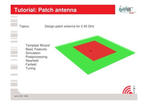
<strong>Tutorial</strong>: <strong>Patch</strong> <strong>antenna</strong><br />
Topics:<br />
Design patch <strong>antenna</strong> for 2.45 GHz<br />
Template Wizard<br />
Basic Features<br />
Simulation<br />
Postprocessing<br />
Nearfield<br />
Farfield<br />
Tuning<br />
serv0, WS, 10/06,<br />
1
Step 1 : Template Wizard<br />
1. Start <strong>Empire</strong> XCcel<br />
2. Open the Antenna template<br />
wizard and choose Microstrip<br />
<strong>antenna</strong><br />
3. Set the resonance frequency to<br />
2.45 GHz<br />
4. Press „Open Template“<br />
5. Select „File – Save As“<br />
6. Select, e.g. C:\tutorial1\patch<br />
(create folder)<br />
Comments:<br />
Using the template “Microstrip <strong>antenna</strong>…”<br />
• Automatic generation of patch<br />
• Automatic generation of lumped port<br />
• Automatic generation of mesh<br />
serv0, WS, 10/06,<br />
2
Step 2: Structure check<br />
1. Switch from Draft to 3D mode<br />
2. Check <strong>antenna</strong> model:<br />
drag left mouse button to move,<br />
middle mouse button to rotate and<br />
right mouse button to zoom<br />
serv0, WS, 10/06,<br />
3
Step 3: <strong>Patch</strong> <strong>antenna</strong> Simulation<br />
1. Click Start Simulation<br />
and view the results on screen as<br />
the simulation is running.<br />
• The microstrip antennna from the template wizard will be<br />
automatically meshed and the simulation will be started<br />
• During the simulation the time pulses are monitored<br />
• After the simulation is finished the s-parameter results are shown<br />
serv0, WS, 10/06,<br />
4
Step 4: 2 D Postprocessing results<br />
1. Switch to Impedance Tab and check input impedance<br />
2. Switch to Farfield Tab and check calculated farfield<br />
serv0, WS, 10/06,<br />
5
Step 5: Nearfield<br />
1. Switch from Farfield to 3D mode<br />
2. Open Layers:<br />
Select +Layers to open Layer overview<br />
3. Turn visibility of Animation layer to ‚On‘:<br />
Press to toggle visibility<br />
serv0, WS, 10/06,<br />
6
Step 6: Farfield<br />
1. Turn visibility of Animation layer to ‚Off‘:<br />
Press to toggle visibility<br />
2. Turn visibility of FF_Aanimation layer to ‚On‘:<br />
Press to toggle visibility<br />
serv0, WS, 10/06,<br />
7
Step 7 : Antenna tuning 1<br />
1. Switch to Draft mode<br />
2. Select patch at right side (use middle mouse button)<br />
3. Choose Advanced<br />
Parameters-Stretch<br />
4. Enter x: dx as shift vector<br />
5. Set parameter range to:<br />
Min: -2000<br />
Max: 0<br />
Value:0<br />
Step: 500 and press ‘OK‘<br />
6. Select patch at left side<br />
7. Choose Advanced->Parameters-Stretch<br />
8. Enter x: -dx as shift vector and confirm with ‘OK‘<br />
9. Select +Parameters and use the slider bar to<br />
change the patch length according to the<br />
parameter value<br />
serv0, WS, 10/06,<br />
8
Step 8 : Antenna tuning 2<br />
1. Open +Simulation Setup and<br />
set ‘End Frequency‘ to 5 GHz<br />
2. Click Convert&Save and<br />
close export log window<br />
3. Switch from Draft to<br />
Advanced mode<br />
4. Select ‘Optimization control‘<br />
5. Press ‘Add Optimization‘<br />
6. Switch to Hosts tab<br />
7. Enable ‘localhost‘<br />
8. Press ‘Start‘ to start<br />
variation<br />
serv0, WS, 10/06,<br />
9
Step 9 : Antenna tuning 3<br />
1. Switch from Advanced to<br />
S-Parameters<br />
2. Switch to‘Setup‘ tab<br />
and press ‚‘reread‘<br />
3. Press ‚view‘<br />
The variation with dx=-500 reaches the<br />
target frequency of 2.45 GHz<br />
serv0, WS, 10/06,<br />
10
Step 10 : Array Setup 1<br />
1. Switch to Draft mode<br />
2. Select File->Save as e.g. c:\tutorial1\patch-array<br />
3. Select the patch and the port (use middle mouse button)<br />
4. Choose Advanced->Multiple Copy<br />
5. Enter: dx=90000,dy=120000,dz=0,<br />
nx=5,ny=3,nz=0 and press ‘OK‘<br />
6. Press ‘Zoom extends‘<br />
7. Open Layers:<br />
Select +Layers to open Layer overview<br />
8. Turn visibility of patch-, ports- and<br />
Near2FarfieldTrans-layer to ‘OFF‘<br />
and from all other layers to ‘ON‘<br />
9. Close +Layer and +Simulation Setup<br />
10. Press ‘Ctrl-A‘ to select all objects<br />
11. Draw an Arrow from (0,0) to (530000,440000)<br />
12. Press Modify ’Assign Arrow’<br />
serv0, WS, 10/06,<br />
11
Step 11 : Array Setup 2<br />
1. Open Layers Select +Layers to open Layer overview<br />
2. Turn visibility of Near2FarfieldTrans-layer to ‘ON’ and all other layers to ’OFF’<br />
3. Select +Structure+Boxes+Box.. to edit the<br />
coordinates of the nf2ff box<br />
4. Adjust the box coordinates to:<br />
P1 (-10000, -10000,0), P1 (540000,450000,25000)<br />
5. Switch all layers to ‘ON’<br />
6. Open +Parameters-> +dx and set<br />
slider to dx=-500<br />
7. Click Start Simulation<br />
serv0, WS, 10/06,<br />
12
Step 12: Array <strong>antenna</strong> Simulation<br />
1. Switch from Draft to<br />
Voltage<br />
2. Switch from Voltage to<br />
S-Parameters<br />
serv0, WS, 10/06,<br />
13
Step 13: Array <strong>antenna</strong> field results<br />
1. Switch from S-parameters to<br />
3D mode<br />
2. Turn visibility of Near2FarfieldTrans-layer and DumpBox<br />
layer to ’OFF’<br />
serv0, WS, 10/06,<br />
14