Installation Manual - Schick Handel
Installation Manual - Schick Handel
Installation Manual - Schick Handel

Create successful ePaper yourself
Turn your PDF publications into a flip-book with our unique Google optimized e-Paper software.
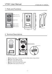
Wiring Terminals on VT581L<br />
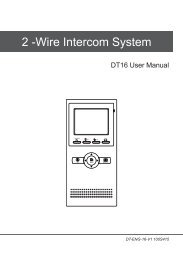
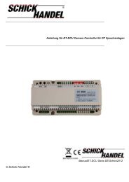
Wiring Diagram 1 (VT581L is powered by Monitor)<br />
Illustration of VT581L PCB Board<br />
5<br />
JP-VD<br />
JP-LK<br />
CN101<br />
DC-<br />
DC+<br />
1R<br />
2W<br />
3Y<br />
4B<br />
JS/VP<br />
JS-OS1<br />
1R<br />
2W<br />
3Y<br />
4B<br />
CAR<br />
D<br />
1R<br />
2W<br />
3Y<br />
4B<br />
JS/AP<br />
JS-OS2<br />
4B<br />
2W<br />
+12<br />
+12<br />
Red<br />
White<br />
Yellow<br />
Black<br />
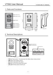
White<br />
Black<br />
+12<br />
Red<br />
White<br />
Yellow<br />
Black<br />
1R<br />
2W<br />
3Y<br />
4B<br />
Wiring Diagram 2 (VT581L is powered by Additional +12V Adaptor)<br />
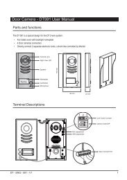
Terminals description<br />
• JS/DC: Connect to JS/AP on the Monitor, or external +12V Power Supply<br />
• JS/VP: Connect to JS/VP on the Monitor<br />
• JS/EB: Connect to external Exit Button<br />
• LB: Connect to latch (Dry Contact Mode)<br />
• LC: Connect to latch (DC output Mode)<br />
• JP/LS: Must be taken off if external Power Supply for latch is used<br />
• SET Jumper: Reserved, always set to right<br />
• ADD Jumper: If two VT581L are installed, set ADD to right for 2nd VT581L<br />
• PROG Button: Button used to authorize master cards<br />
- 3 -<br />
- 4 -