Create successful ePaper yourself
Turn your PDF publications into a flip-book with our unique Google optimized e-Paper software.
5-<strong>BAY</strong> <strong>RAID</strong> <strong>STATION</strong><br />
Manual
Content<br />
1. Features 3<br />
1.1 Overview 3<br />
1.2 SATA features 3<br />
1.3 USB features 4<br />
2. Specifications 4<br />
3. System requirements 4<br />
4. The device at a glance 4<br />
4.1 Rear panel 5<br />
4.2 The LED indications 5<br />
5. Package contents 7<br />
6. Getting started 7<br />
6.1 HDD installation 7<br />
6.2 Power on/off 9<br />
6.3 eSATA slot bracket installation 9<br />
7. Configuration 10<br />
7.1 Preparation 10<br />
7.2 Changing the host connection 11<br />
7.3 Disconnecting an USB device 11<br />
7.4 HDD HotPlug 11<br />
8. Setting the <strong>RAID</strong> mode 11<br />
8.1 CLEAN mode 12<br />
8.2 CLONE mode with HotSpare 13<br />
8.3 R1 mode with HotSpare 16<br />
8.4 R10 mode with HotSpare 18<br />
8.5 R3 mode with HotSpare 20<br />
8.6 R5 mode with HotSpare 23<br />
9. Rebuilding a redundant or HotSpare drive 25<br />
9.1 Rebuilding a redundant drive 26<br />
9.2 Rebuilding a HotSpare drive 27<br />
10. Troubleshooting 29<br />
11. Appendix 30<br />
11.1 CLEAN mode 30<br />
11.2 LARGE mode 30<br />
11.3 CLONE mode 31<br />
11.4 R0 mode 32<br />
11.5 R1 mode 32<br />
11.6 R10 mode 33<br />
11.7 R3 mode 34<br />
11.8 R5 mode 35<br />
<br />
5-bay raid station 2
Dear customer!<br />
Congratulations for purchasing one premium quality SHARKOON product.<br />
For a long life time and to take full advantage of this product we recommend that you read<br />
this manual completely.<br />
Have a good time with our product!<br />
SHARKOON Technologies<br />
1. Features<br />
1.1 Overview<br />
• External <strong>RAID</strong> case with five mounting bays for 2.5" and 3.5" SATA HDDs<br />
• Supported modes: Clean/Single, Large, Clone and <strong>RAID</strong> 0/1/3/5/10<br />
• Easy <strong>RAID</strong> mode configuration<br />
• Automatic rebuild in Clone and <strong>RAID</strong> 1/3/5/10 mode<br />
• HotSpare support in Clone and <strong>RAID</strong> 1/3/5/10 mode<br />
• Supports HDD roaming<br />
• Internal interfaces: SATA I and II (compatible with SATA III)<br />
• External interfaces: eSATA and USB3.0<br />
• Fast Swap mechanism for easy HDD handling<br />
• Premium quality craftsmanship<br />
• On/off button<br />
• LED indications for power, HDD activity and rebuild mode<br />
• Pre-installed fan<br />
1.2 SATA features<br />
• Port Multiplier Functionality<br />
• Auto-negotiation between SATA I (1.5 Gbps) and SATA II (3 Gbps)<br />
• Hot-Plug support in CLEAN mode<br />
• Supports Native Command Queue (NCQ)<br />
• Supports Port Multiplier Aware and non-Port Multiplier Aware host in <strong>RAID</strong> mode<br />
• Supports Asynchronous Signal Recovery<br />
• Supports Spread Spectrum Clocking<br />
• Supports BIST and Loopback mode<br />
• Supports 48-bit LBA addressing<br />
• Supports Asynchronous Notification<br />
<br />
5-bay raid station 3
1.3 USB features<br />
• Compatible with USB Super Speed, High Speed and Full Speed<br />
• Compatible with OHCI/UHCI/EHCI hosts<br />
• Supports Mass Storage Class<br />
2. Specifications<br />
• Five mounting bays for 2.5" and 3.5" SATA HDDs<br />
• Metal chassis (SECC) and plastic front panel (ABS)<br />
• Dimensions: 282 x 150 x 215 mm (L x W x H)<br />
• Weight: ~4 kg<br />
• 250 W full range power supply<br />
3. System requirements<br />
• Intel Pentium-III 500 MHz equivalent or faster<br />
• Windows XP, Windows Vista, Windows 7 with the latest Service Packs<br />
• 64 MB of RAM (minimum)<br />
• Super VGA (800 x 600) or higher resolution display with at least 256 colors<br />
• Mouse or compatible pointing device<br />
• SATA connection: Intel ICH or optional Host Bus Adapter card and associated software<br />
drivers with Port Multiplier support<br />
• USB connection: USB 2.0 or 3.0 direct host connection<br />
4. The device at a glance<br />
<br />
5-bay raid station 4
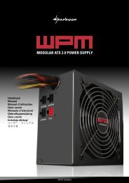
4.1 Rear panel<br />
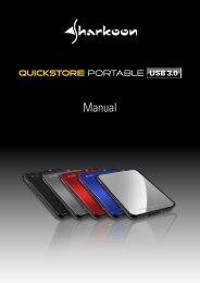
4.2 The LED indications<br />
<br />
5-bay raid station 5
1. Power LED<br />
DESCRIPTION<br />
Power On<br />
Power Off<br />
GREEN LED<br />
On<br />
Off<br />
2. PC Link LED<br />
DESCRIPTION<br />
PC Link Unplugged / No Power<br />
PC Link Plugged (Idle)<br />
PC Link Plugged (Active)<br />
GREEN LED<br />
Off<br />
On<br />
On<br />
3. Front panel LEDs<br />
DESCRIPTION GREEN LED RED LED<br />
HDD Unplugged / No Power Off Off<br />
HDD Plugged (Idle) On Off<br />
HDD Plugged (Active) Blink (On) Off<br />
Error State (one or more bad partial volumes) Off On<br />
HDD Rebuild (a physical partition is being Off<br />
Blink (On)<br />
rebuild; e.g. Mirroring Mode)<br />
4. HDD tray LEDs<br />
DESCRIPTION GREEN (UPPER) GREEN (LOWER)<br />
HDD Unplugged / No Power Off Off<br />
HDD Plugged (Idle) On Off<br />
HDD Plugged (Active) Blink (On) Off<br />
Error State (one or more bad partial volumes) Off On<br />
HDD Rebuild (a physical partition is being<br />
rebuild; e.g. Mirroring Mode)<br />
On<br />
Blink (On)<br />
<br />
5-bay raid station 6
5. Package contents<br />
• 5-Bay <strong>RAID</strong> Station<br />
• 5x HDD mounting frames<br />
• 1x USB3.0 cable<br />
• 1x eSATA cable<br />
• 1x power cord<br />
• 20x mounting screws for 2.5" HDDs/SSDs<br />
• 20x mounting screws for 3.5" HDDs<br />
• 1x SATA to eSATA cable with bracket<br />
6. Getting started<br />
6.1 HDD installation<br />
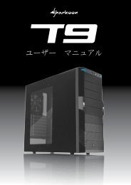
1. Open the front door, then unlock the HDD mounting frame lock and remove the HDD<br />
mounting frame from the 5-<strong>BAY</strong> <strong>RAID</strong> <strong>STATION</strong> (fig. 1).<br />
Fig. 1<br />
2. Place the HDD into the HDD mounting frame (fig. 2).<br />
Fig. 2<br />
<br />
5-bay raid station 7
3. Use the mounting screws to securely attach the HDD to the mounting frame (fig. 3).<br />
Fig. 3<br />
4. Slide the HDD mounting frame back into the 5-<strong>BAY</strong> <strong>RAID</strong> <strong>STATION</strong> (fig. 4).<br />
Fig. 4<br />
5. Close the front door to complete the HDD installation (fig. 5).<br />
Fig. 5<br />
<br />
5-bay raid station 8
6.2 Power on/off<br />
Press the power button to switch on the device. Press again to power it off.<br />
6.3 eSATA slot bracket installation<br />
1. Remove the anchor screw of the slot bezel and take it from the rear side of your PC<br />
case (fig. 6).<br />
Fig. 6<br />
<br />
5-bay raid station 9
2. Insert the included eSATA bracket into the slot bracket and attach it to the case using<br />
the anchor screw (fig. 7).<br />
Fig. 7<br />
3. Connect the SATA cable of the eSATA bracket to a free SATA port of your PC<br />
mainboard.<br />
7. Configuration<br />
7.1 Preparation<br />
1. SATA host connection<br />
This installation guide assumes that you have already connected the 5-<strong>BAY</strong> <strong>RAID</strong><br />
<strong>STATION</strong> to a SATA or eSATA host controller with Port Multiplier (PM) support.<br />
Note:<br />
If you use a host controller that does not provide Port Multiplier support (such as Intel<br />
ICH), the CLEAN mode is not available when configuring the 5-<strong>BAY</strong> <strong>RAID</strong> <strong>STATION</strong>.<br />
Only one disk is available on the host computer.<br />
2. USB host connection<br />
If you are connecting your 5-<strong>BAY</strong> <strong>RAID</strong> <strong>STATION</strong> using an USB connection to your<br />
host, the USB port should be compliant with USB2.0 or 3.0.<br />
<br />
5-bay raid station 10
7.2 Changing the host connection<br />
The 5-<strong>BAY</strong> <strong>RAID</strong> <strong>STATION</strong> supports both USB and eSATA host connections, although only<br />
one connection can be attached at the same time.<br />
If it becomes necessary to switch the host connection between eSATA and USB, the host<br />
computer system and the 5-<strong>BAY</strong> <strong>RAID</strong> <strong>STATION</strong> should both be powered down prior to<br />
changing the host connection, in order to avoid data loss. After changing the host<br />
connection, both devices can be powered-on again to continue operation with the new<br />
host connection.<br />
7.3 Disconnecting an USB device<br />
USB3.0 external devices provide support for Plug & Play connection, so that your USB<br />
storage device can be connected and disconnected while the computer is running. To<br />
prevent data loss or other failures, we recommend the following procedure when<br />
disconnecting your USB3.0 storage device from your host computer system:<br />
Before you shut down your PC remove the 5-Bay <strong>RAID</strong> Station from your system’s<br />
hardware configuration by double-clicking the symbol in the task bar. A menu will<br />
open up. Select the 5-Bay <strong>RAID</strong> Station to securely remove it. Switch off the device and<br />
shut down your PC.<br />
7.4 HDD HotPlug<br />
The hard disk drives should not be hot-plugged, but can be unplugged while the<br />
system is running. However, to avoid data corruption or loss, make sure that the host<br />
system is not currently using any drive that is about to be unplugged.<br />
8. Setting the <strong>RAID</strong> mode<br />
To define a storage mode for the first time, make sure that the hard disk drives are<br />
mounted, then turn off the power before setting the <strong>RAID</strong> MODE SWITCHES on the rear<br />
side of the 5-<strong>BAY</strong> <strong>RAID</strong> <strong>STATION</strong> to the desired mode.<br />
To change the storage mode afterwards, set the <strong>RAID</strong> mode switches to the desired<br />
position. Press and hold the setup button, then switch on the device to create the<br />
new virtual volume(s).<br />
Notes:<br />
Creating new virtual volumes will erase any existing data saved on the volumes!<br />
Back up your data before reconfiguring the storage mode!<br />
<br />
5-bay raid station 11
8.1 CLEAN mode<br />
The CLEAN mode requires a minimum of one HDD.<br />
1. Switch off the device (fig. 8).<br />
Fig. 8<br />
2. Toggle the <strong>RAID</strong> mode switches to the desired <strong>RAID</strong> mode according to the<br />
following chart (fig. 9):<br />
Fig. 9<br />
3. Press and hold the setup button (fig. 10).<br />
Fig. 10<br />
<br />
5-bay raid station 12
4. Switch on the device and then release the setup button to complete the <strong>RAID</strong> mode<br />
setting (fig. 11).<br />
Fig. 11<br />
8.2 CLONE mode with HotSpare<br />
The CLONE mode with HotSpare drive requires a minimum of three drives to implement.<br />
1. Switch off the device (fig. 12).<br />
Fig. 12<br />
2. Insert two HDDs into the topmost drive bays (fig. 13).<br />
Fig. 13<br />
<br />
5-bay raid station 13
3. Toggle the <strong>RAID</strong> mode switches to CLONE (fig. 14).<br />
Fig. 14<br />
4. Press and hold the setup button (fig. 15).<br />
Fig. 15<br />
5. Switch on the device and then release the setup button (fig. 16).<br />
Fig. 16<br />
<br />
5-bay raid station 14
6. Switch off the device (fig. 17).<br />
Fig. 17<br />
7. Insert the HotSpare drive into the third HDD bay (fig. 18).<br />
Fig. 18<br />
8. Switch on the device to complete the <strong>RAID</strong> mode setting (fig. 19).<br />
Fig. 19<br />
<br />
5-bay raid station 15
8.3 R1 mode with HotSpare<br />
1. Switch off the device (fig. 20).<br />
Fig. 20<br />
2. Insert three HDDs into the topmost drive bays (fig. 21).<br />
Fig. 21<br />
3. Toggle the <strong>RAID</strong> mode switches to R1/R10 (fig. 22).<br />
Fig. 22<br />
<br />
5-bay raid station 16
4. Press and hold the setup button (fig. 23).<br />
Fig. 23<br />
5. Switch on the device and then release the setup button to complete the <strong>RAID</strong> mode<br />
setting (fig. 24).<br />
Fig. 24<br />
<br />
5-bay raid station 17
8.4 R10 mode with HotSpare<br />
1. Switch off the device (fig. 25).<br />
Fig. 25<br />
2. Insert five HDDs into the drive bays (fig. 26).<br />
Fig. 26<br />
3. Toggle the <strong>RAID</strong> mode switches to R1/R10 (fig. 27).<br />
Fig. 27<br />
<br />
5-bay raid station 18
4. Press and hold the setup button (fig. 28).<br />
Fig. 28<br />
5. Switch on the power and then release the setup button to complete the <strong>RAID</strong> mode<br />
setting (fig. 29).<br />
Fig. 29<br />
<br />
5-bay raid station 19
8.5 R3 mode with HotSpare<br />
The R3 mode with HotSpare HDD requires a minimum of four drives to implement.<br />
1. Switch off the device (fig. 30).<br />
Fig. 30<br />
2. Insert three drives into the topmost drive bays (fig. 31).<br />
Fig. 31<br />
3. Toggle the <strong>RAID</strong> mode switches to R3 (fig. 32).<br />
Fig. 32<br />
<br />
5-bay raid station 20
4. Press and hold the setup button (fig. 33).<br />
Fig. 33<br />
5. Switch on the device and then release the setup button (fig. 34).<br />
Fig. 34<br />
6. Switch off the device (fig. 35).<br />
Fig. 35<br />
<br />
5-bay raid station 21
7. Insert the hot spare HDD into the 4th HDD bay (fig. 36).<br />
Fig. 36<br />
8. Switch on the device to complete the <strong>RAID</strong> mode setting (fig. 37).<br />
Fig. 37<br />
<br />
5-bay raid station 22
8.6 R5 mode with HotSpare<br />
The R5 mode with HotSpare HDD requires a minimum of four drives to implement.<br />
1. Switch off the device (fig. 38).<br />
Fig. 38<br />
2. Insert three drives into the topmost drive bays (fig. 39).<br />
Fig. 39<br />
3. Toggle the <strong>RAID</strong> mode switches to R5 (fig. 40).<br />
Fig. 40<br />
<br />
5-bay raid station 23
4. Press and hold the setup button (fig. 41).<br />
Fig. 41<br />
5. Switch on the device and then release the setup button (fig. 42).<br />
Fig. 42<br />
6. Switch off the device (fig. 43).<br />
Fig. 43<br />
<br />
5-bay raid station 24
7. Insert the HotSpare drive into the fourth HDD bay (fig. 44).<br />
Fig. 44<br />
8. Switch on the device to complete the <strong>RAID</strong> mode setting (fig. 45).<br />
Fig. 45<br />
9. Rebuilding a redundant or HotSpare drive<br />
The 5-<strong>BAY</strong> <strong>RAID</strong> <strong>STATION</strong> duplicates all data to separate drives in order to protect against<br />
data loss due to drive failure in CLONE, R1, R3, R5, and R10 MODE.<br />
The following example illustrates the procedure of rebuilding a redundant or HotSpare<br />
drive.<br />
<br />
5-bay raid station 25
9.1 Rebuilding a redundant drive<br />
1. If drive 2 fails, please remove it from the device (fig. 46).<br />
Fig. 46<br />
2. Switch off the device (fig. 47).<br />
Fig. 47<br />
3. Replace the defective HDD with a hard disk drive of the same capacity or bigger (fig. 48).<br />
Fig. 48<br />
<br />
5-bay raid station 26
4. Switch on the device (fig. 49).<br />
Fig. 49<br />
5. The 5-<strong>BAY</strong> <strong>RAID</strong> <strong>STATION</strong> will start rebuilding the virtual volume automatically<br />
(rebuild speed: approximately 200 GB/hour).<br />
9.2 Rebuilding a HotSpare drive<br />
1. If there is a HotSpare drive inserted into drive bay 5, and the drive 2 fails, the<br />
HotSpare drive 5 will replace the broken down drive. The rebuild procedure will start<br />
automatically.<br />
To install a new HotSpare drive, remove the defective drive 2 (fig. 50).<br />
Fig. 50<br />
<br />
5-bay raid station 27
2. Switch off the device (fig. 51).<br />
Fig. 51<br />
3. Replace the defective HDD with a hard disk drive of the same capacity or bigger (fig. 52).<br />
Fig. 52<br />
4. Switch on the device (fig. 53).<br />
Fig. 53<br />
5. The 5-<strong>BAY</strong> <strong>RAID</strong> <strong>STATION</strong> will replace the HotSpare drive in mounting bay 2 automatically.<br />
<br />
5-bay raid station 28
10. Troubleshooting<br />
1. Device is not recognized<br />
Make sure all cables have been properly connected.<br />
For the USB3.0 controller the latest drivers and the newest firmware must be installed.<br />
2. Cannot operate in O/S<br />
Make sure the device is supported by your operating system.<br />
3. Transfer speed is slow<br />
If the device is connected via the USB2.0 interface, the speed will be around 30 MB/sec<br />
only.<br />
4. When formatting under Windows XP/Vista/7, the dialog box “Unfinished formatting”<br />
is displayed<br />
Windows XP/Vista/7 cannot format HDDs with capacities above 32 GB into FAT32,<br />
please choose NTFS as data format.<br />
5. Can the LARGE mode be used, when HDDs with different capacities or brand are<br />
built in<br />
Yes.<br />
6. When the system is damaged in LARGE mode, is it still possible to read the data<br />
No. The system is different from a <strong>RAID</strong>; the entire disk cannot be read.<br />
<br />
5-bay raid station 29
11. Appendix<br />
11.1. CLEAN mode<br />
Function: In CLEAN mode each hard drive is displayed separately as one drive.<br />
Notes:<br />
When using a SATA host controller, CLEAN mode should only be used if the SATA host<br />
controller provides Port Multiplier (PM) support. If a host is not PM-aware, only a single<br />
drive is displayed (drive 1).<br />
The CLEAN mode will not delete the drives partition if the drives were used as single<br />
drive before.<br />
11.2 LARGE mode<br />
Function:<br />
The LARGE mode concatenates a series of physical hard drives into a single large<br />
volume, creating a seamless expansion of virtual volumes beyond the physical limitations<br />
of singularly connected hard drives.<br />
Notes:<br />
The hard drives 1 to 5 are concatenated into a single virtual volume in the figure above<br />
with a storage capacity that is equal to the sum of each of the physical hard drives 1 to 5.<br />
It is also possible to create a LARGE volume using only a single hard disk drive connected<br />
to Port 1. However, it is not possible to expand an existing LARGE volume by adding<br />
another hard disk drive and still preserve any existing data on that volume.<br />
<br />
5-bay raid station 30
11.3 CLONE mode<br />
Function:<br />
The CLONE mode duplicates all data on separate drives to protect against data loss due<br />
to drive failure. One drive clones the others at all times. Every write operation goes to all<br />
drives.<br />
Advantage:<br />
CLONE mode provides the highest level of data protection for critical data. The resulting<br />
storage capacity of the virtual CLONE volume will be equivalent to the size of one hard<br />
drive (if all drives are the same) or the smallest of the drives (if they are different).<br />
If a drive fails (maximum four drives), the CLONE volume is still usable. When the offline<br />
drive comes back online, the appliance begins a rebuild process immediately one by one<br />
(in case more than one HDD failed) to restore the data. During this procedure the LED<br />
indications will notify you that a rebuild is in progress.<br />
Notes:<br />
Although the volume remains available during the rebuild process, the volume is<br />
susceptible to data loss through damage to the remaining drive until redundancy is<br />
restored at the end of the rebuild and verification process. Host access takes precedence<br />
over the rebuild process. If you continue to use the CLONE volume during the rebuild, the<br />
rebuild process will take a longer time to complete, and the host data transfer performance<br />
will also be affected.<br />
It is also possible to create a CLONE volume using one hard disk drive connected to Port 1<br />
of the 5-<strong>BAY</strong> <strong>RAID</strong> <strong>STATION</strong>, although no clone will occur until a second hard disk drive<br />
is connected. With only one hard disk drive connected, the CLONE volume will be available,<br />
although no data protection will be provided until a second hard disk drive is connected.<br />
<br />
5-bay raid station 31
11.4 R0 mode<br />
Function:<br />
In R0 mode the data is spread across all hard disks.<br />
Advantage/disadvantage:<br />
R0 mode represents the best data speed but no data redundancy. R0 mode accelerates<br />
hard disk drive operating speed by using many disks simultaneously. Hard disk drive data<br />
segments are written to different disks, which increases performance.<br />
To implement the R0 mode storage policy, the 5-<strong>BAY</strong> <strong>RAID</strong> <strong>STATION</strong> creates a single<br />
virtual volume that is striped across all hard drives, with a storage capacity that is five<br />
times the capacity of the smallest drive.<br />
11.5 R1 mode<br />
Function:<br />
In R1 mode all data is duplicated on separate drives to protect against data loss due to<br />
drive failure. One drive mirrors the other at all times. Every write operation addresses<br />
both drives.<br />
Advantage/disadvantage:<br />
R1 mode provides the highest level of data protection for critical data.<br />
The resulting storage capacity of the virtual R1 volume will be equivalent to the size of<br />
one hard drive (if both drives are of the same size) or the smaller of the two drives (if they<br />
are of different size).<br />
<br />
5-bay raid station 32
Notes:<br />
If one drive fails, the R1 volume is still usable. When the offline drive comes back online,<br />
the appliance commences a rebuild process immediately to restore data redundancy. The<br />
LED indications will notify you that a rebuild is in progress.<br />
Although the volume remains available during the rebuild process, the volume is susceptible<br />
to data loss through damage to the remaining drive until redundancy is restored at the<br />
end of the rebuild and verification process. Host access takes precedence over the rebuild<br />
process. If you continue to use the R1 volume during the rebuild, the rebuild process will<br />
take a longer time to complete, and the host data transfer performance will also be affected.<br />
11.6 R10 mode<br />
Function:<br />
The R10 mode combines the features of both the R0 and the R1 mode. Performance is<br />
provided through the use of R0 mode, while adding the fault tolerance of R1. The<br />
implementation of R10 requires four drives. The drives are assigned as two sets of striped<br />
pairs. The data is written to the R1 set and provides data redundancy. Alternating blocks<br />
of data are then striped (R0) across another R1 set. This provides improved speed. The<br />
resulting storage capacity of the virtual R10 volume will be two times the smallest drive<br />
capacity.<br />
Advantage/disadvantage:<br />
If one drive fails, the R10 volume is still usable. When the offline drive comes back online,<br />
the appliance begins a rebuild process immediately to restore data redundancy. During<br />
this procedure the LED indications will notify you that a rebuild is in progress.<br />
Notes:<br />
Although the volume remains available during the rebuild process, the volume is susceptible<br />
to data loss through damage to the remaining drive until redundancy is restored at the<br />
end of the rebuild and verification process. Host access takes precedence over the rebuild<br />
process. If you continue to use the R10 volume during the rebuild, the rebuild process<br />
will take a longer time to complete, and the host data transfer performance will also be<br />
affected.<br />
<br />
5-bay raid station 33
11.7 R3 mode<br />
Function:<br />
The R3 mode requires a minimum of three drives to implement. The R3 mode adds fault<br />
tolerance to drive striping by adding parity information to the data. R3 mode dedicates<br />
the equivalent of one drive for storing parity stripes. The data and parity information is<br />
arranged on the drive array so that parity is written to one drive. There are at least three<br />
volumes to create a virtual R3 volume. The following example illustrates how the parity is<br />
rotated from drive to drive.<br />
Advantage/disadvantage:<br />
The R3 mode uses less capacity for protection and is the preferred method to reduce the<br />
cost per megabyte for larger installations.<br />
In exchange for low overhead necessary to implement protection, the R3 mode degrades<br />
performance for all write operations. The parity calculations for R3 mode may result in<br />
write performance that is somewhat slower than the write performance to a single drive.<br />
The resulting storage capacity of the virtual R3 volume will be four times of the smallest<br />
drive.<br />
If one drive fails, the virtual R3 volume is still usable. When the offline drive comes back<br />
online, the appliance begins a rebuild process immediately to restore data redundancy.<br />
During this procedure the LED indications will notify you that a rebuild is in progress.<br />
Notes:<br />
Although the volume remains available during the rebuild process, the volume is susceptible<br />
to data loss through damage to the remaining drive until redundancy is restored at the<br />
end of the rebuild and verification process. Host access takes precedence over the rebuild<br />
process. If you continue to use the virtual R3 volume during the rebuild, the rebuild<br />
process will take a longer time to complete, and the host data transfer performance will<br />
also be affected.<br />
<br />
5-bay raid station 34
11.8 R5 mode<br />
Function:<br />
The R5 mode requires a minimum of three drives to implement. The R5 mode adds fault<br />
tolerance to drive striping by including parity information with the data. R5 mode<br />
dedicates the equivalent of one drive for storing parity stripes. The data and parity<br />
information is arranged on the drive array so that parity is written to all drives. There are<br />
at least three members to a virtual R5 volume. The following example illustrates how the<br />
parity is rotated from drive to drive.<br />
Advantage/disadvantage:<br />
The R5 mode uses less capacity for protection and is the preferred method to reduce the<br />
cost per megabyte for larger installations.<br />
In exchange for low overhead necessary to implement protection, the R5 mode degrades<br />
performance for all write operations. The parity calculations for R5 mode may result in<br />
write performance that is somewhat slower than the write performance of a single drive.<br />
The resulting storage capacity of the virtual R5 volume will be four times of the smallest<br />
drive.<br />
If one drive fails, the virtual R5 volume is still usable, but it is in a vulnerable state<br />
because its mirrored hard drive is inaccessible. When the offline drive comes back online,<br />
the appliance begins a rebuild process immediately to restore data redundancy. During<br />
this procedure the LED indications will notify you that a rebuild is in progress.<br />
<br />
5-bay raid station 35
Notes:<br />
Although the volume remains available during the rebuild process, the volume is susceptible<br />
to data loss through damage to the remaining drive until redundancy is restored at the<br />
end of the rebuild and verification process. Host access takes precedence over the rebuild<br />
process. If you continue to use the virtual R5 volume during the rebuild, the rebuild<br />
process will take a longer time to complete, and the host data transfer performance will<br />
also be affected.<br />
<br />
5-bay raid station 36
Legal disclaimer:<br />
For potential loss of data, especially due to inappropriate handling, SHARKOON assumes<br />
no liability.<br />
All named products and descriptions are trademarks and/or registered trademarks of the<br />
respective manufacturers and are accepted as protected.<br />
As a continuing policy of product improvement at SHARKOON, the design and specifications<br />
are subject to change without prior notice. National product specifications may vary.<br />
All rights reserved especially (also in extracts) for translation, reprinting, reproduction by<br />
copying or other technical means. Infringements will lead to compensation.<br />
All rights reserved especially in case of assignation of patent or utility patent. Means of delivery<br />
and technical modifications reserved.<br />
Disposal of your old product<br />
Your product is designed and manufactured with high quality materials and components,<br />
which can be recycled and reused.<br />
When this crossed-out wheeled bin symbol is attached to a product, it means the product is<br />
covered by the European Directive 2002/96/EC.<br />
Please be informed about the local separate collection system for electrical and electronic<br />
products.<br />
Please act according to your local rules and do not dispose of your old products with your<br />
normal household waste. The correct disposal of your old product will help prevent potential<br />
negative consequences to the environment and human health.<br />
© SHARKOON Technologies 2012<br />
www.sharkoon.com<br />
<br />
5-bay raid station 37