M1500-UPS-PFP Programmable UPS - LOAD - Furman Sound
M1500-UPS-PFP Programmable UPS - LOAD - Furman Sound
M1500-UPS-PFP Programmable UPS - LOAD - Furman Sound

Create successful ePaper yourself
Turn your PDF publications into a flip-book with our unique Google optimized e-Paper software.
Basic Operation (continued)<br />
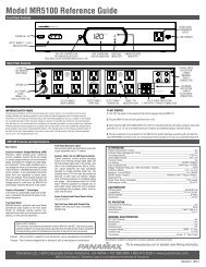
FRONT PANEL DISPLAY LED DESCRIPTIONS<br />
Power On Indicator<br />
This LED is illuminated when<br />
the utility condition is normal<br />
and the <strong>UPS</strong> outlets are providing<br />
clean, protected power.<br />
Line Fault Indicator<br />
This LED will illuminate to warn the user that a<br />
wiring problem such as a bad/missing ground or<br />
reversed wiring exists within the AC receptacle.<br />
If illuminated, disconnect all equipment and contact<br />
an electrician to insure outlet is properly wired.<br />
Unsafe Voltage Indicator<br />
This LED will illuminate to inform the user that<br />
an unsafe line voltage is present and that the<br />
<strong>UPS</strong> has switched to battery power. This could<br />
be either an over-voltage or under-voltage.<br />
Battery Level Indicator<br />
This is a visual indication of the<br />
battery charge. If battery capacity<br />
is under 25%, no indicator<br />
LED will illuminate and <strong>UPS</strong><br />
starts beeping (if the audible<br />
alarm is enabled).<br />
POWER ON<br />
BATTERY LEVEL LINE FAULT<br />
<strong>LOAD</strong> LEVEL<br />
UNSAFE VOLTAGE<br />
BATTERY MODE<br />
AVR MODE<br />
1 2 3 4<br />
Load Level Indicator<br />
This is a visual indication of the<br />
<strong>UPS</strong> load.<br />
The 1st arrow will illuminate when<br />
the load is above 25%, the 2nd<br />
above 50% and the 3rd above<br />
75%. The 4th arrow will flash<br />
when the load is between 85%<br />
and 100%.<br />
Battery Mode Indicator<br />
This illuminates during utility failure or<br />
an unsafe voltage condition, indicating<br />
that the battery is supplying power to<br />
the connected equipment.<br />
AVR Indicator<br />
This indicates that the <strong>UPS</strong> is operating in automatic voltage regulation mode. When the LED is<br />
illuminated continuously, it indicates an input over-voltage and the <strong>UPS</strong> unit reduces (bucks) the<br />
voltage to the normal operating range. When the LED is flashing, it indicates that the input line<br />
voltage is low and that the <strong>UPS</strong> is increasing (boosts) input voltage to the normal range.<br />
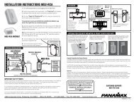
REAR PANEL DESCRIPTION<br />
Non-Critical-Load Outlets<br />
Four battery powered, surge<br />
protected and AVR outlets for<br />
connected equipment insures<br />
temporary uninterrupted operation<br />
of connected equipment<br />
during a power failure.<br />
Critical Load Outlets<br />
Two battery powered, surge<br />
protected and AVR outlets for<br />
critical-load equipment<br />
insures temporary uninterrupted<br />
operation of connected<br />
equipment during a power<br />
failure.<br />
AC Power<br />
Cord Input<br />
Receptacle<br />
IR Control Section<br />
Learning Control Switches – Push to program or test the IR function<br />
IR Detector Window – Receives the IR signal to be learned<br />
Indicator LED’s – Indicates learning status<br />
Output Delay Switches – Sets the desired time delay between a power failure<br />
and when the IR signals are sent to the connected equipment<br />
IR Output Jacks – Standard 1/8” (3.5mm) mono jack for connection to an IR<br />
flasher (IR flashers not included)<br />
OUTPUT DELAY<br />
IR DETECTOR<br />
NON CRITICAL<br />
<strong>LOAD</strong> OUTLET<br />
BANK<br />
3<br />
IR1<br />
30 SEC. 5 MIN.<br />
1<br />
2<br />
CRITICAL<br />
<strong>LOAD</strong><br />
OUTLET<br />
BANK<br />
AC INPUT<br />
MAIN<br />
IR2<br />
IR OUTPUT<br />
PROGRAM / TEST<br />
RS232 CONTROL<br />
IN<br />
OUT<br />
Circuit Breakers for<br />
Overload Protection<br />
Resettable circuit<br />
breakers provide<br />
optimal overload<br />
protection.<br />
RS232 Serial Communication Port<br />
The serial port allows connection and communication between the<br />
<strong>UPS</strong> and a computer system. This allows the installer to program<br />
a number of variables including the Critical Load Battery Threshold.<br />
See the software documentation for more information.<br />
RJ11/RJ45 Jacks<br />
Ports protect standard<br />
telephone line,<br />
modem, or network<br />
cable.<br />
USA & Canada (800) 472-5555 • (707) 283-5900 • Fax (707) 283-5901<br />
3