A Compact Single/Dual-Band Printed Inverted-F Type Antenna ...
A Compact Single/Dual-Band Printed Inverted-F Type Antenna ...
A Compact Single/Dual-Band Printed Inverted-F Type Antenna ...

Create successful ePaper yourself
Turn your PDF publications into a flip-book with our unique Google optimized e-Paper software.
3. FDTD/FEM-Simulations and Measurements on Prototypes of <strong>Dual</strong>-<strong>Band</strong> <strong>Antenna</strong>s<br />
In the open literature there are less papers on printed multi-band antennas, compared to the many<br />
publications on multi-band PIFAs. In [2] a so-called stacked IFA for dual-band operation is presented.<br />
The PCB-area needed for this antenna structure is quite large, due to its stacked assembly. Our dualband<br />
antenna presented in the following has a more compact design. The qualitative outline of the<br />
structure is shown in Fig. 2 and is called dual-band bended-h antenna (dual BhA). Our objective in this<br />
section is to design a compact dual-band antenna for WLAN operation within the ISM 2.4 and 5 GHz<br />
bands. The matching line (secondary radiator) with its dimensions M1 and M2 (see Fig. 2) is located<br />
in the reactive near-field of the main radiator, yielding a coupling between main and secondary<br />
radiator. The bandwidth for the 2.4 GHz resonance of the main radiator is reduced compared to the<br />
single-band BhA of section 2 – in this case there is just a little coupling between main radiator and the<br />
matching line above the ground-plane. But a bandwidth of around 100 MHz is sufficient for the lower<br />
ISM band from 2.40 to 2.4835 GHz. For the IEEE 802.11a standard altogether three subbands exists.<br />
The first subband is from 5.15 to 5.25 GHz and it allows up to 16 dBm transmitting RF power. The<br />
second one is from 5.25 to 5.35 GHz with 23 dBm maximum power, and the third one, mainly<br />
intended for outdoor applications, is from 5.725 to 5.825 GHz with 29 dBm max. power. The overall<br />
BW is therefore 675 MHz. The length and position of the secondary radiator has been optimized with<br />
EMPIRE to have approx. 100 MHz of bandwidth in the lower ISM band and close to 675 MHz for<br />
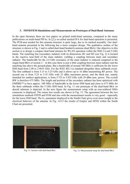
the three subbands within the 5 GHz ISM band. In Fig. 11 one prototype of the dual-band BhA on<br />
duroid substrate is depicted. In the next figure the measurement setup with an non-soldered SMA<br />
connector is displayed. The return loss results are shown in Fig. 13. The agreement between the two<br />
simulations methods FDTD and FEM and also with the measurement results is very good – especially<br />
for the lower ISM band. The S11-parameter displayed in the Smith Chart gives even more insight to the<br />
electrical behavior of the antenna. In Fig. 14/15 the results of Empire and HFSS within the Smith<br />
Chart are presented.<br />
Fig. 11: Section with dual-band BhA Fig. 12: Measurement setup for dual-band BhA